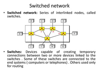
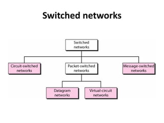
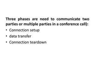
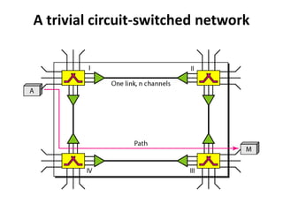
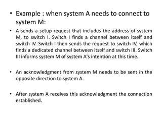
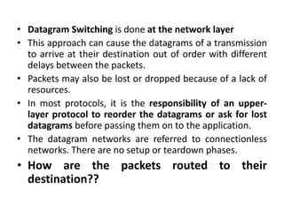
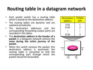
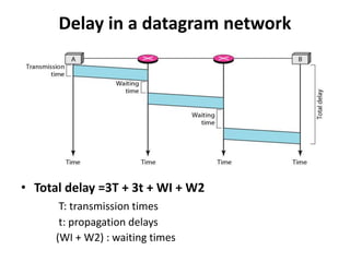
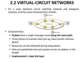
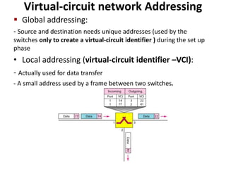
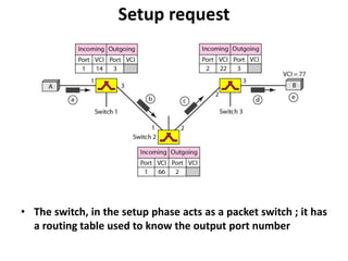
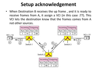
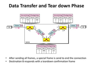
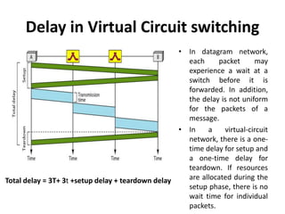
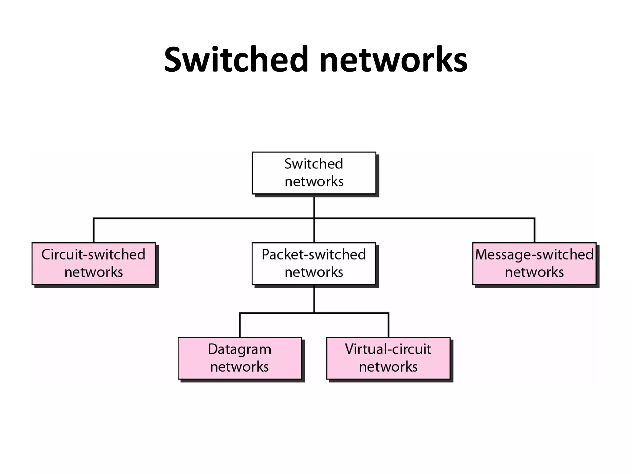
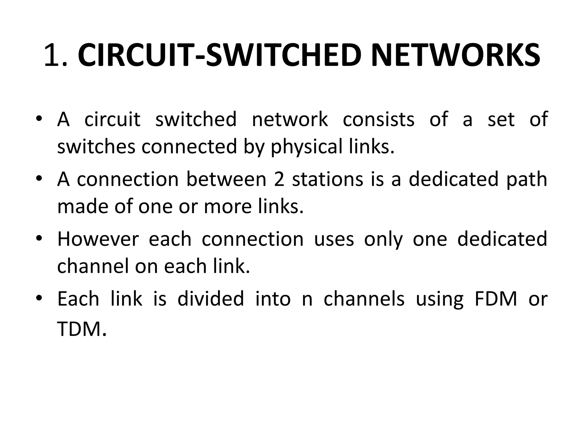
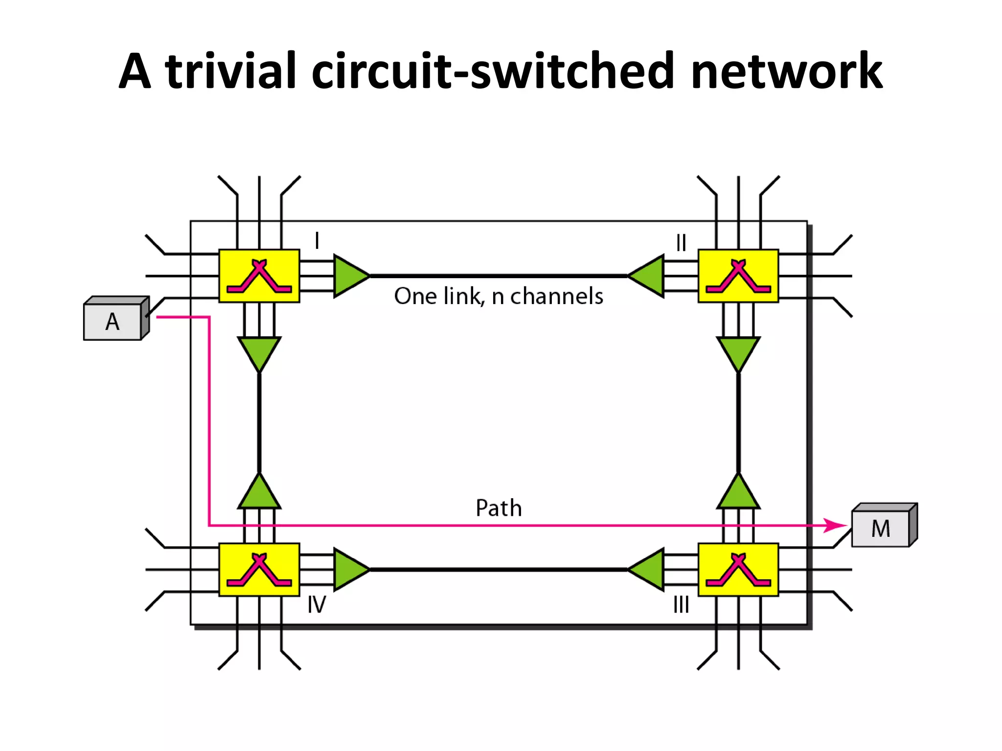
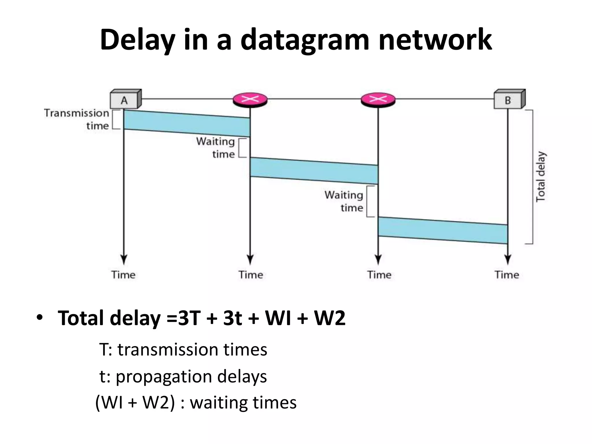
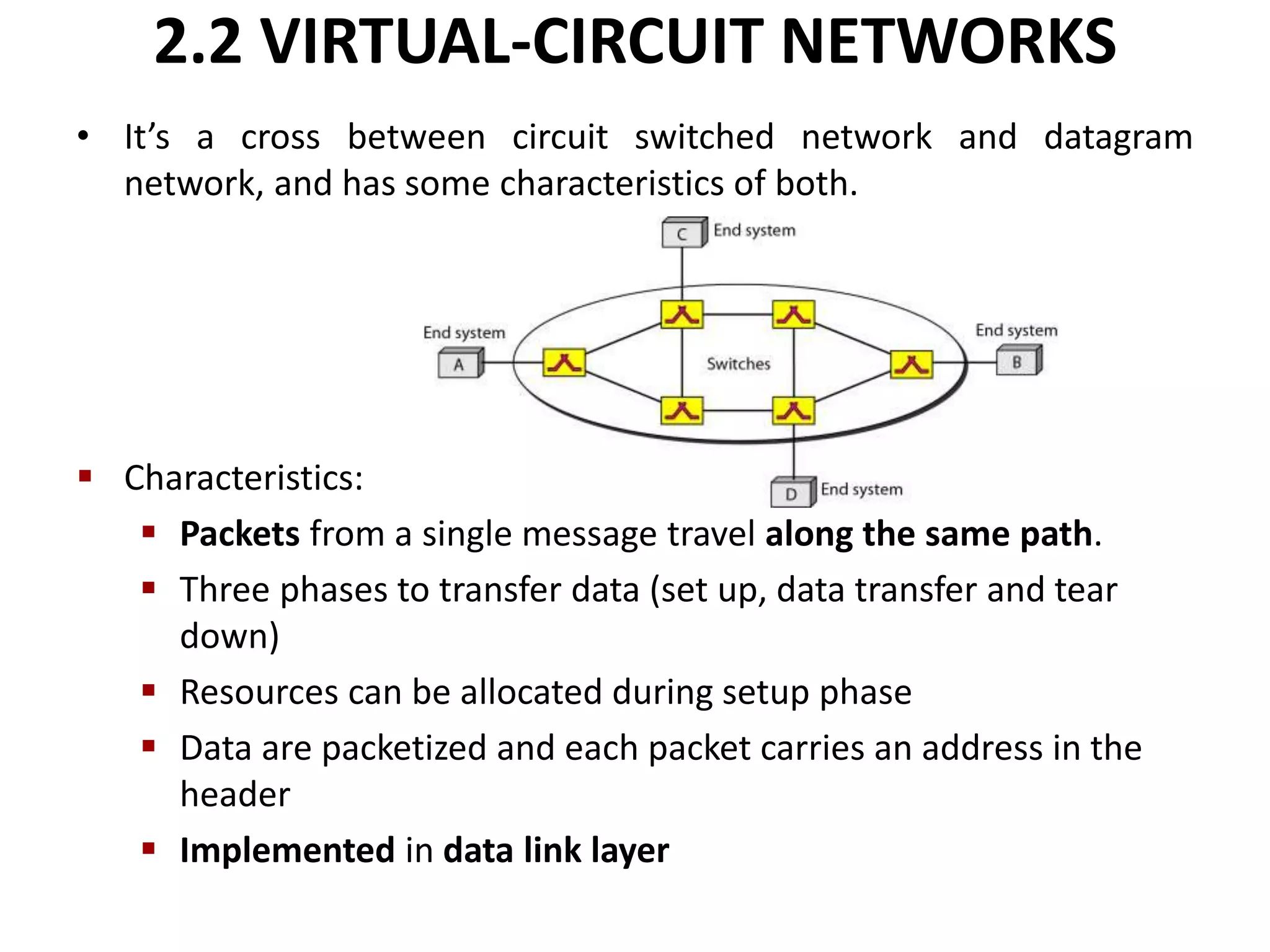
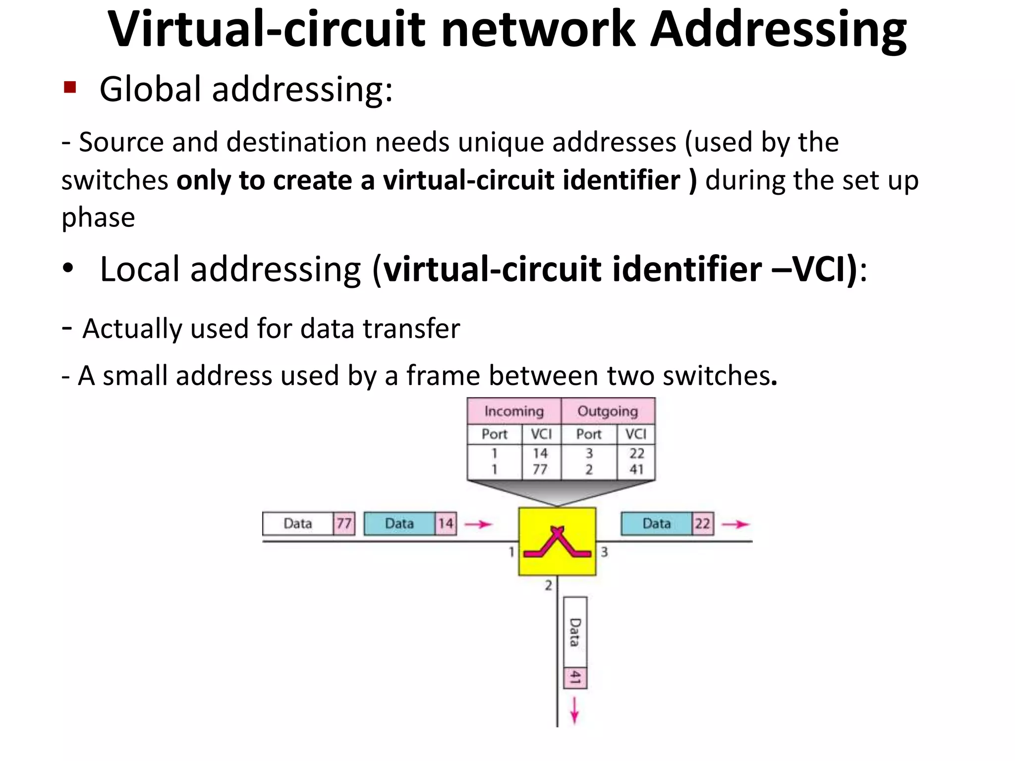
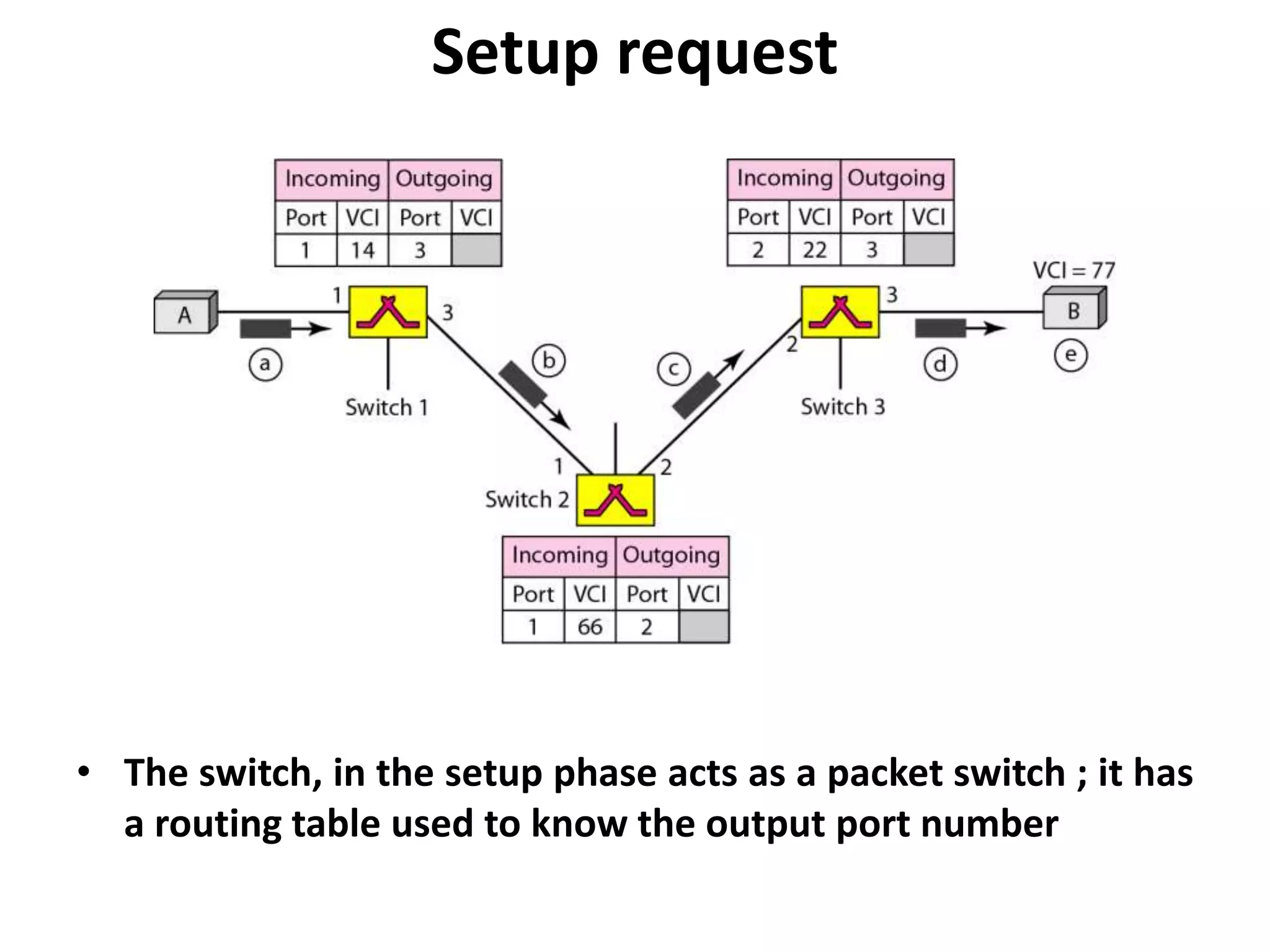
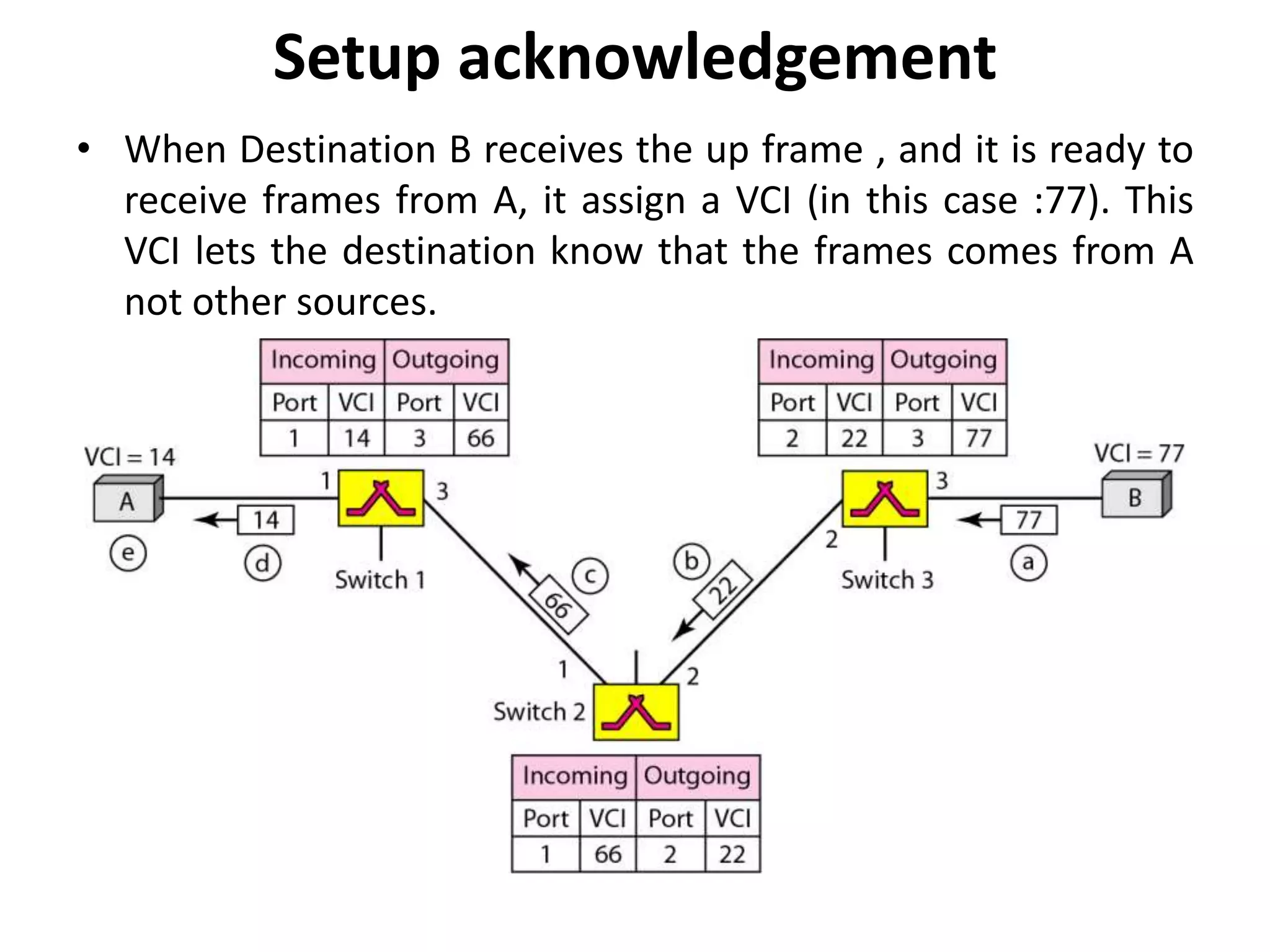
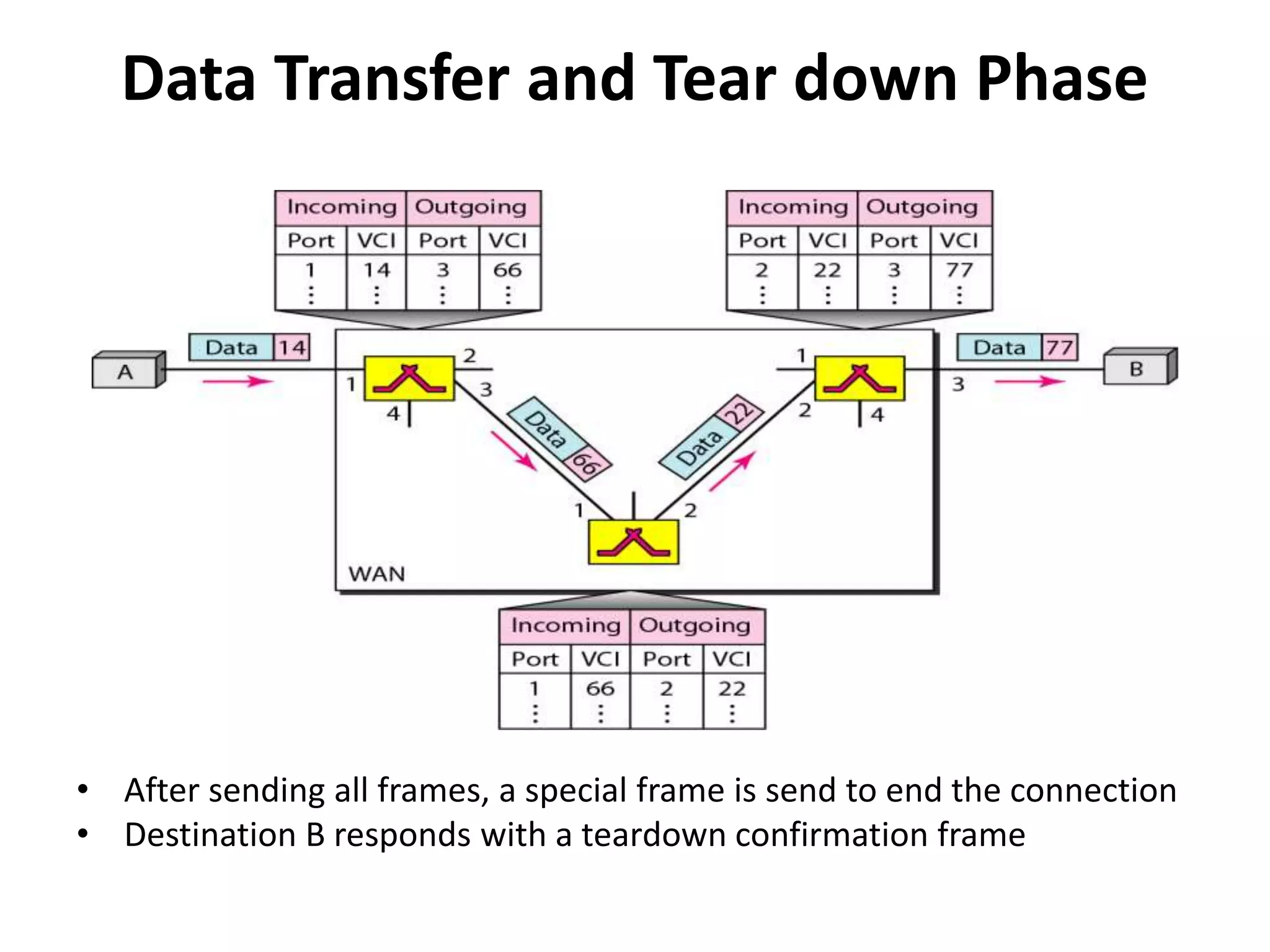
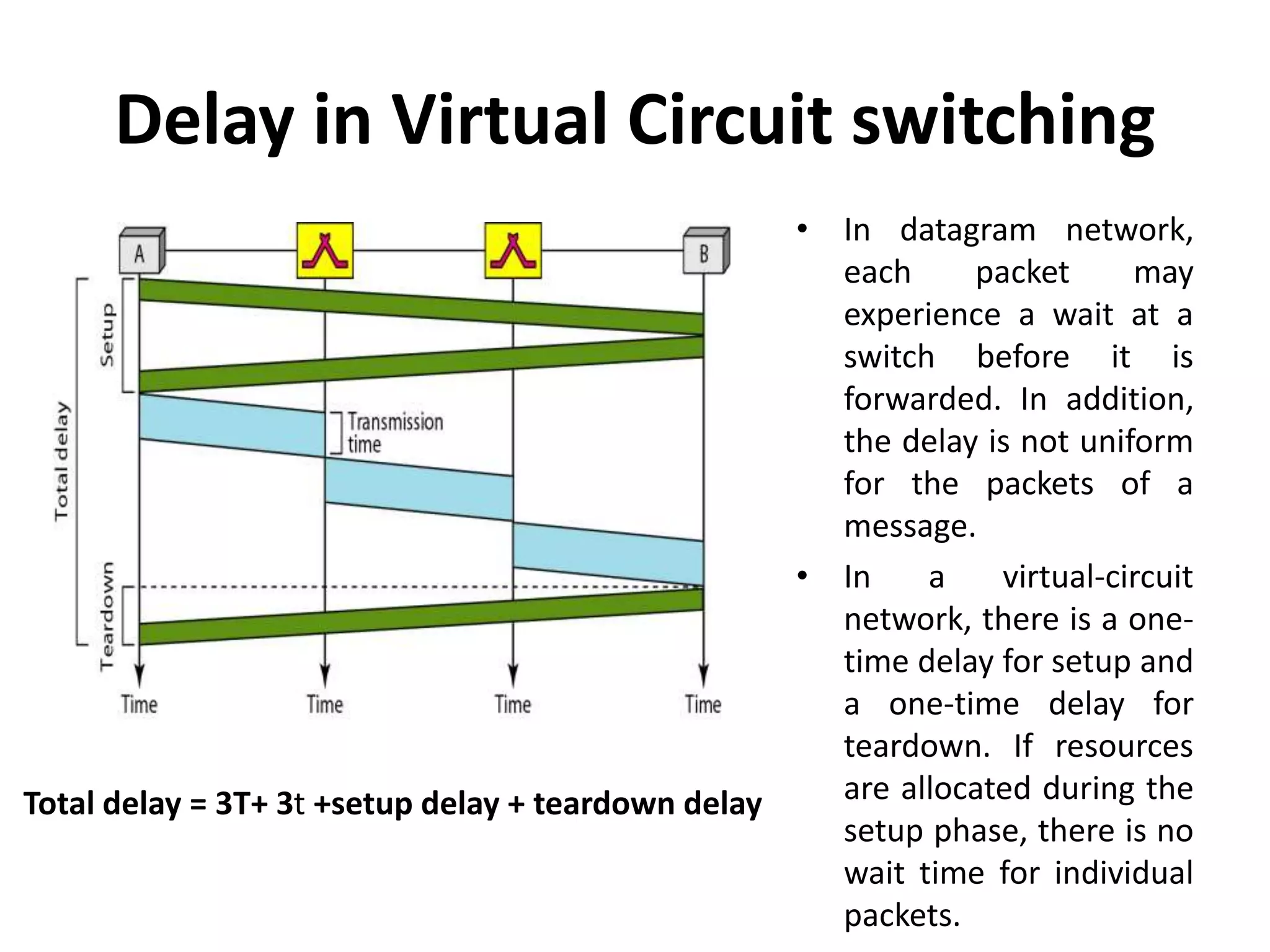
KEMBAR78
Computer network switching | PPTX
Computer Network Switching 
by: 
Vishal Sharma 
Lecturer, NIT Hamirpur 
vishalfzd@gmail.com
Switched network 
• Switched network: Series of interlinked nodes, called 
switches. 
• Switches: Devices capable of creating temporary 
connections between two or more devices linked to the 
switches . Some of these switches are connected to the 
end systems ( computers or telephones) . Others used only 
for routing
Switched networks
1. CIRCUIT-SWITCHED NETWORKS 
• A circuit switched network consists of a set of 
switches connected by physical links. 
• A connection between 2 stations is a dedicated path 
made of one or more links. 
• However each connection uses only one dedicated 
channel on each link. 
• Each link is divided into n channels using FDM or 
TDM.
Three phases are need to communicate two 
parties or multiple parties in a conference call): 
• Connection setup 
• data transfer 
• Connection teardown
• The setup phase: means creating dedicated channels 
between the switches. 
• Data Transfer Phase: After the establishment of the 
dedicated circuit (channels), the two parties can 
transfer data. 
• Teardown Phase: When one of the parties needs to 
disconnect, a signal is sent to each switch to release 
the resources.
A trivial circuit-switched network
• Example : when system A needs to connect to 
system M: 
• A sends a setup request that includes the address of system 
M, to switch I. Switch I finds a channel between itself and 
switch IV. Switch I then sends the request to switch IV, which 
finds a dedicated channel between itself and switch III. Switch 
III informs system M of system A's intention at this time. 
• An acknowledgment from system M needs to be sent in the 
opposite direction to system A. 
• After system A receives this acknowledgment the connection 
established.
Circuit-switched network 
• Circuit switching takes place at the physical layer 
• Data transferred between the two stations are not 
packetized. The data are a continuous flow sent by the source 
station and received by the destination station 
• There is no addressing involved during data transfer. Of 
course, there is end-to-end addressing used during the setup 
phase.
Efficiency 
• circuit-switched networks are not so efficient as 
the resources are allocated during the entire 
duration of the connection. 
• These resources are unavailable to other 
connections.
Delay
2. PACKET SWITCHED NETWORK 
• Messages need to be divided into packets. 
• Size of the packet is determined by the network and 
the governing protocol. 
• no resource reservation, but allocated on demand. 
• The allocation is done first come, first served based 
• When a switch receives a packets , the packet must 
wait if there are other packets being processed, this 
lack of reservation may create delay
2.1 DATAGRAM NETWORKS 
• Each packet (called as datagrams in this approach) is treated 
independently of all others 
• All packets (or datagrams) belong to the same message may 
travel different paths to reach their destination .
• Datagram Switching is done at the network layer 
• This approach can cause the datagrams of a transmission 
to arrive at their destination out of order with different 
delays between the packets. 
• Packets may also be lost or dropped because of a lack of 
resources. 
• In most protocols, it is the responsibility of an upper-layer 
protocol to reorder the datagrams or ask for lost 
datagrams before passing them on to the application. 
• The datagram networks are referred to connectionless 
networks. There are no setup or teardown phases. 
• How are the packets routed to their 
destination??
Routing table in a datagram network 
• Each packet switch has a routing table 
which is based on the destination address. 
• The routing tables are dynamic and are 
updated periodically. 
• The destination addresses and the 
corresponding forwarding output ports are 
recorded in the tables. 
• The destination address in the header of a 
packet in a datagram network remains the 
same during the entire journey of the 
packet. 
• When the switch receives the packet, this 
destination address is examined; the 
routing table is consulted to find the 
corresponding port through which the 
packet should be forwarded.
Efficiency 
• Better than that of a circuit-switched network. 
• Resources are allocated only when there are packets 
to be transferred. If a source sends a packet and 
there is a delay of a few minutes before another 
packet can be sent, the resources can be reallocated 
during these minutes for other packets from other 
sources. 
• Switching in the Internet is done by using the 
datagram approach to packet switching at 
the network layer
Delay in a datagram network 
• Total delay =3T + 3t + WI + W2 
T: transmission times 
t: propagation delays 
(WI + W2) : waiting times
2.2 VIRTUAL-CIRCUIT NETWORKS 
• It’s a cross between circuit switched network and datagram 
network, and has some characteristics of both. 
 Characteristics: 
 Packets from a single message travel along the same path. 
 Three phases to transfer data (set up, data transfer and tear 
down) 
 Resources can be allocated during setup phase 
 Data are packetized and each packet carries an address in the 
header 
 Implemented in data link layer
Virtual-circuit network Addressing 
 Global addressing: 
- Source and destination needs unique addresses (used by the 
switches only to create a virtual-circuit identifier ) during the set up 
phase 
• Local addressing (virtual-circuit identifier –VCI): 
- Actually used for data transfer 
- A small address used by a frame between two switches.
Setup request 
• The switch, in the setup phase acts as a packet switch ; it has 
a routing table used to know the output port number
Setup acknowledgement 
• When Destination B receives the up frame , and it is ready to 
receive frames from A, it assign a VCI (in this case :77). This 
VCI lets the destination know that the frames comes from A 
not other sources.
Data Transfer and Tear down Phase 
• After sending all frames, a special frame is send to end the connection 
• Destination B responds with a teardown confirmation frame
Delay in Virtual Circuit switching 
Total delay = 3T+ 3t +setup delay + teardown delay 
• In datagram network, 
each packet may 
experience a wait at a 
switch before it is 
forwarded. In addition, 
the delay is not uniform 
for the packets of a 
message. 
• In a virtual-circuit 
network, there is a one-time 
delay for setup and 
a one-time delay for 
teardown. If resources 
are allocated during the 
setup phase, there is no 
wait time for individual 
packets.
Thank You

Computer network switching

  • 1.
    Computer Network Switching by: Vishal Sharma Lecturer, NIT Hamirpur vishalfzd@gmail.com
  • 2.
    Switched network •Switched network: Series of interlinked nodes, called switches. • Switches: Devices capable of creating temporary connections between two or more devices linked to the switches . Some of these switches are connected to the end systems ( computers or telephones) . Others used only for routing
  • 3.
  • 4.
    1. CIRCUIT-SWITCHED NETWORKS • A circuit switched network consists of a set of switches connected by physical links. • A connection between 2 stations is a dedicated path made of one or more links. • However each connection uses only one dedicated channel on each link. • Each link is divided into n channels using FDM or TDM.
  • 5.
    Three phases areneed to communicate two parties or multiple parties in a conference call): • Connection setup • data transfer • Connection teardown
  • 6.
    • The setupphase: means creating dedicated channels between the switches. • Data Transfer Phase: After the establishment of the dedicated circuit (channels), the two parties can transfer data. • Teardown Phase: When one of the parties needs to disconnect, a signal is sent to each switch to release the resources.
  • 7.
  • 8.
    • Example :when system A needs to connect to system M: • A sends a setup request that includes the address of system M, to switch I. Switch I finds a channel between itself and switch IV. Switch I then sends the request to switch IV, which finds a dedicated channel between itself and switch III. Switch III informs system M of system A's intention at this time. • An acknowledgment from system M needs to be sent in the opposite direction to system A. • After system A receives this acknowledgment the connection established.
  • 9.
    Circuit-switched network •Circuit switching takes place at the physical layer • Data transferred between the two stations are not packetized. The data are a continuous flow sent by the source station and received by the destination station • There is no addressing involved during data transfer. Of course, there is end-to-end addressing used during the setup phase.
  • 10.
    Efficiency • circuit-switchednetworks are not so efficient as the resources are allocated during the entire duration of the connection. • These resources are unavailable to other connections.
  • 11.
  • 12.
    2. PACKET SWITCHEDNETWORK • Messages need to be divided into packets. • Size of the packet is determined by the network and the governing protocol. • no resource reservation, but allocated on demand. • The allocation is done first come, first served based • When a switch receives a packets , the packet must wait if there are other packets being processed, this lack of reservation may create delay
  • 13.
    2.1 DATAGRAM NETWORKS • Each packet (called as datagrams in this approach) is treated independently of all others • All packets (or datagrams) belong to the same message may travel different paths to reach their destination .
  • 14.
    • Datagram Switchingis done at the network layer • This approach can cause the datagrams of a transmission to arrive at their destination out of order with different delays between the packets. • Packets may also be lost or dropped because of a lack of resources. • In most protocols, it is the responsibility of an upper-layer protocol to reorder the datagrams or ask for lost datagrams before passing them on to the application. • The datagram networks are referred to connectionless networks. There are no setup or teardown phases. • How are the packets routed to their destination??
  • 15.
    Routing table ina datagram network • Each packet switch has a routing table which is based on the destination address. • The routing tables are dynamic and are updated periodically. • The destination addresses and the corresponding forwarding output ports are recorded in the tables. • The destination address in the header of a packet in a datagram network remains the same during the entire journey of the packet. • When the switch receives the packet, this destination address is examined; the routing table is consulted to find the corresponding port through which the packet should be forwarded.
  • 16.
    Efficiency • Betterthan that of a circuit-switched network. • Resources are allocated only when there are packets to be transferred. If a source sends a packet and there is a delay of a few minutes before another packet can be sent, the resources can be reallocated during these minutes for other packets from other sources. • Switching in the Internet is done by using the datagram approach to packet switching at the network layer
  • 17.
    Delay in adatagram network • Total delay =3T + 3t + WI + W2 T: transmission times t: propagation delays (WI + W2) : waiting times
  • 18.
    2.2 VIRTUAL-CIRCUIT NETWORKS • It’s a cross between circuit switched network and datagram network, and has some characteristics of both.  Characteristics:  Packets from a single message travel along the same path.  Three phases to transfer data (set up, data transfer and tear down)  Resources can be allocated during setup phase  Data are packetized and each packet carries an address in the header  Implemented in data link layer
  • 19.
    Virtual-circuit network Addressing  Global addressing: - Source and destination needs unique addresses (used by the switches only to create a virtual-circuit identifier ) during the set up phase • Local addressing (virtual-circuit identifier –VCI): - Actually used for data transfer - A small address used by a frame between two switches.
  • 20.
    Setup request •The switch, in the setup phase acts as a packet switch ; it has a routing table used to know the output port number
  • 21.
    Setup acknowledgement •When Destination B receives the up frame , and it is ready to receive frames from A, it assign a VCI (in this case :77). This VCI lets the destination know that the frames comes from A not other sources.
  • 22.
    Data Transfer andTear down Phase • After sending all frames, a special frame is send to end the connection • Destination B responds with a teardown confirmation frame
  • 23.
    Delay in VirtualCircuit switching Total delay = 3T+ 3t +setup delay + teardown delay • In datagram network, each packet may experience a wait at a switch before it is forwarded. In addition, the delay is not uniform for the packets of a message. • In a virtual-circuit network, there is a one-time delay for setup and a one-time delay for teardown. If resources are allocated during the setup phase, there is no wait time for individual packets.
  • 24.