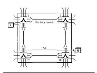
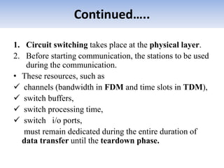
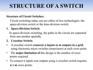
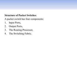
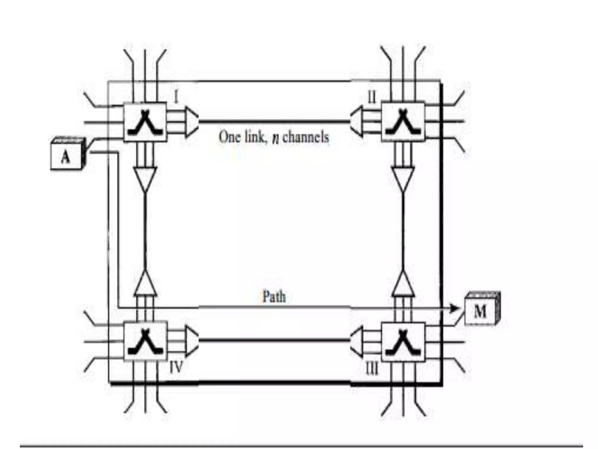
KEMBAR78
Unit -1 Circuit Switch and Data gram Switch | PPTX
Unit -1
Overview & Physical
Layer
Prepared by,
P.Nivetha,
Asst.Prof,
Dept. of BCA
Bon Secours College for Women,
Thanjavur.
Chapter -8
8.1- CIRCUIT-SWITCHED NETWORKS
8.2- DATAGRAM NETWORKS
8.4 –STRUCTURE OF A SWITCH
CIRCUIT-SWITCHED NETWORKS
• A circuit-switched network consists of a set of
switches connected by physical links.
• A connection between two stations is a
dedicated path made of one or more links.
• Each link is normally divided into n channels
by using FDM or TDM.
• The end systems, such as computers or
telephones, are directly connected to a switch.
Continued…..
• When end system A needs to communicate with end system
M, -system A needs to request a connection to M.
• That must be accepted by all switches as well as by M
itself. This is called the setup phase.
• A circuit (channel) is reserved on each link, and the
combination of circuits or channels defines the dedicated
path.
• After the dedicated path made of connected circuits
(channels) is established, data transfer can take place.
• After all data have been transferred, the circuits are tom
down.
Continued…..
1. Circuit switching takes place at the physical layer.
2. Before starting communication, the stations to be used
during the communication.
• These resources, such as
 channels (bandwidth in FDM and time slots in TDM),
 switch buffers,
 switch processing time,
 switch i/o ports,
must remain dedicated during the entire duration of
data transfer until the teardown phase.
Continued…..
3. Data transferred between the two stations are
not packetized (physical layer transfer of the
signal).
• The data are a continuous flow sent by the
source station and received by the destination
station.
4. There is no addressing involved during data
transfer. There is end-to end addressing used
during the setup phase.
Three Phases
• Setup Phase
• Data Transfer Phase
• Teardown Phase
• Efficiency
• Delay
Setup Phase
• Before the two parties can communicate, dedicated
circuit needs to be established.
• The end systems are normally connected through
dedicated lines to the switches which defines a
dedicated path.
• In the next step to making a connection, an
acknowledgment from system M needs to be sent in
the opposite direction to system A.
• Only after system A receives this acknowledgment
is the connection established.
(Refer Diagram)
Data Transfer Phase
After the establishment of the dedicated circuit
the two parties can transfer data.
Teardown Phase
When one of the parties needs to disconnect, a
signal is sent to each switch to release the
resources.
Efficiency
1. It is not as efficient as the other two types of
networks.
2. Because resources are allocated during the
entire duration of the connection.
3. In a telephone network, people normally
terminate the communication when they have
finished their conversation.
4. In CN, a computer can be connected to another
computer even if there is no activity for a long
time.
Delay
• Has low efficiency.
• The delay in this type of network is minimal.
• The total delay is due to the time needed to
create the connection,
transfer data and
disconnect the circuit.
Continue…
Delay caused by the setup is the sum of four parts:
1. The propagation time of the source computer request (slope of
the first gray box),
2. The request signal transfer time (height of the first gray box),
3. The propagation time of the acknowledgment from the
destination computer (slope of the second gray box).
4. The signal transfer time of the acknowledgment (height of
the second gray box).
• The delay due to data transfer is the sum of twoparts:
• The propagation time (slope of the colored box) and data
transfer time (height of the colored box), which can be very
long.
• The third box shows the time needed to tear down the circuit.
DATAGRAM NETWORKS
• If the message is going to pass through a packet-switched
network, it needs to be divided into packets of fixed or
variable size.
• The size of the packet is determined by the network and the
governing protocol.
• In packet switching, there is no resource allocation for a
packet.
• This means that there is no reserved bandwidth on the
links, and there is no scheduled processing time for each
packet.
• Resources are allocated on demand.
Continue…
• The allocation is done on a first come, first-served basis.
• When a switch receives a packet, no matter what is the source
• or destination, the packet must wait if there are other packets
being processed.
For example,
• we do not have a reservation at a restaurant, we might have to
wait.
• In a datagram network, each packet is treated independently of
all others.
• Packets in this approach are referred to as datagram's.
• Datagram switching is normally done at the network layer.
• The switches in a datagram network are traditionally referred to
as routers.
Figure 8.7 Explanation
• All four packets (or datagrams) belong to the same message,
but may travel different paths to reach their destination.
• This approach can cause the datagrams of a transmission to
arrive at their destination out of order with different delays
between the packets.
• Packets may also be lost or dropped because of a lack of
resources.
• The datagram networks are sometimes referred to as
connectionless networks.
• There are no setup or teardown phases.
• Each packet is treated the same by a switch regardless of its
source or destination.
Routing Table
• If there are no setup or teardown phases, how are the
packets routed to their destinations in a datagram network?
• In this type of network, each switch (or packet switch) has a
routing table which is based on the destination address.
• The routing tables are dynamic and are updated
periodically.
• The destination addresses and the corresponding
forwarding output ports are recorded in the tables.
• This is different from the table of a circuit switched
network in which each entry is created when the setup phase
is completed and deleted when the teardown phase is over.
Destination Address
• Every packet in a datagram network carries a header that
contains other information such as destination address of the
packet.
• When the switch receives the packet, destination address is
examined.
• The routing table is consulted to find the corresponding port
through which the packet should be forwarded.
Efficiency
• The efficiency of a datagram network is better than that
of a circuit-switched network
• Resources are allocated only when there are packets to be
transferred.
• If a source sends a packet and there is a delay of a few
minutes before another packet can be sent.
• The resources can be reallocated during these minutes for
other packets from other sources.
Delay
• There may be greater delay in a datagram
network than in a virtual-circuit network.
• There are no setup and teardown phases.
• Each packet may experience a wait at a
• switch before it is forwarded.
Total delay =3T+ 3t + WI + W2
STRUCTURE OF A SWITCH
Structure of Circuit Switches:
Circuit switching today can use either of two technologies: the
space-division switch or the time-division switch.
1. Space-Division Switch:
In space-division switching, the paths in the circuit are separated
from one another spatially.
2. Crossbar Switch:
• A crossbar switch connects n inputs to m outputs in a grid,
using electronic micro switches (transistors) at each cross point.
• The major limitation of this design is the number of cross
points required.
• To connect n inputs tom outputs using a crossbar switch requires
n x m cross points.
3. Multistage Switch :
• Which combines crossbar switches in several (normally
three) stages.
• In a single crossbar switch, only one row or column
(one path) is active for any connection.
• So we need N x N cross points.
• If we can allow multiple paths inside the switch, we can
decrease the number of cross points.
• Each Cross point in the middle stage can be accessed by
multiple cross points in the first or third stage.
Structure of Packet Switches:
A packet switch has four components:
1. Input Ports,
2. Output Ports,
3. The Routing Processor,
4. The Switching Fabric.
Thank You

Unit -1 Circuit Switch and Data gram Switch

  • 1.
    Unit -1 Overview &Physical Layer Prepared by, P.Nivetha, Asst.Prof, Dept. of BCA Bon Secours College for Women, Thanjavur.
  • 2.
    Chapter -8 8.1- CIRCUIT-SWITCHEDNETWORKS 8.2- DATAGRAM NETWORKS 8.4 –STRUCTURE OF A SWITCH
  • 3.
    CIRCUIT-SWITCHED NETWORKS • Acircuit-switched network consists of a set of switches connected by physical links. • A connection between two stations is a dedicated path made of one or more links. • Each link is normally divided into n channels by using FDM or TDM. • The end systems, such as computers or telephones, are directly connected to a switch.
  • 5.
    Continued….. • When endsystem A needs to communicate with end system M, -system A needs to request a connection to M. • That must be accepted by all switches as well as by M itself. This is called the setup phase. • A circuit (channel) is reserved on each link, and the combination of circuits or channels defines the dedicated path. • After the dedicated path made of connected circuits (channels) is established, data transfer can take place. • After all data have been transferred, the circuits are tom down.
  • 6.
    Continued….. 1. Circuit switchingtakes place at the physical layer. 2. Before starting communication, the stations to be used during the communication. • These resources, such as  channels (bandwidth in FDM and time slots in TDM),  switch buffers,  switch processing time,  switch i/o ports, must remain dedicated during the entire duration of data transfer until the teardown phase.
  • 7.
    Continued….. 3. Data transferredbetween the two stations are not packetized (physical layer transfer of the signal). • The data are a continuous flow sent by the source station and received by the destination station. 4. There is no addressing involved during data transfer. There is end-to end addressing used during the setup phase.
  • 8.
    Three Phases • SetupPhase • Data Transfer Phase • Teardown Phase • Efficiency • Delay
  • 9.
    Setup Phase • Beforethe two parties can communicate, dedicated circuit needs to be established. • The end systems are normally connected through dedicated lines to the switches which defines a dedicated path. • In the next step to making a connection, an acknowledgment from system M needs to be sent in the opposite direction to system A. • Only after system A receives this acknowledgment is the connection established. (Refer Diagram)
  • 10.
    Data Transfer Phase Afterthe establishment of the dedicated circuit the two parties can transfer data. Teardown Phase When one of the parties needs to disconnect, a signal is sent to each switch to release the resources.
  • 11.
    Efficiency 1. It isnot as efficient as the other two types of networks. 2. Because resources are allocated during the entire duration of the connection. 3. In a telephone network, people normally terminate the communication when they have finished their conversation. 4. In CN, a computer can be connected to another computer even if there is no activity for a long time.
  • 12.
    Delay • Has lowefficiency. • The delay in this type of network is minimal. • The total delay is due to the time needed to create the connection, transfer data and disconnect the circuit.
  • 13.
    Continue… Delay caused bythe setup is the sum of four parts: 1. The propagation time of the source computer request (slope of the first gray box), 2. The request signal transfer time (height of the first gray box), 3. The propagation time of the acknowledgment from the destination computer (slope of the second gray box). 4. The signal transfer time of the acknowledgment (height of the second gray box). • The delay due to data transfer is the sum of twoparts: • The propagation time (slope of the colored box) and data transfer time (height of the colored box), which can be very long. • The third box shows the time needed to tear down the circuit.
  • 14.
    DATAGRAM NETWORKS • Ifthe message is going to pass through a packet-switched network, it needs to be divided into packets of fixed or variable size. • The size of the packet is determined by the network and the governing protocol. • In packet switching, there is no resource allocation for a packet. • This means that there is no reserved bandwidth on the links, and there is no scheduled processing time for each packet. • Resources are allocated on demand.
  • 15.
    Continue… • The allocationis done on a first come, first-served basis. • When a switch receives a packet, no matter what is the source • or destination, the packet must wait if there are other packets being processed. For example, • we do not have a reservation at a restaurant, we might have to wait. • In a datagram network, each packet is treated independently of all others. • Packets in this approach are referred to as datagram's. • Datagram switching is normally done at the network layer. • The switches in a datagram network are traditionally referred to as routers.
  • 17.
    Figure 8.7 Explanation •All four packets (or datagrams) belong to the same message, but may travel different paths to reach their destination. • This approach can cause the datagrams of a transmission to arrive at their destination out of order with different delays between the packets. • Packets may also be lost or dropped because of a lack of resources. • The datagram networks are sometimes referred to as connectionless networks. • There are no setup or teardown phases. • Each packet is treated the same by a switch regardless of its source or destination.
  • 18.
    Routing Table • Ifthere are no setup or teardown phases, how are the packets routed to their destinations in a datagram network? • In this type of network, each switch (or packet switch) has a routing table which is based on the destination address. • The routing tables are dynamic and are updated periodically. • The destination addresses and the corresponding forwarding output ports are recorded in the tables. • This is different from the table of a circuit switched network in which each entry is created when the setup phase is completed and deleted when the teardown phase is over.
  • 19.
    Destination Address • Everypacket in a datagram network carries a header that contains other information such as destination address of the packet. • When the switch receives the packet, destination address is examined. • The routing table is consulted to find the corresponding port through which the packet should be forwarded.
  • 20.
    Efficiency • The efficiencyof a datagram network is better than that of a circuit-switched network • Resources are allocated only when there are packets to be transferred. • If a source sends a packet and there is a delay of a few minutes before another packet can be sent. • The resources can be reallocated during these minutes for other packets from other sources.
  • 21.
    Delay • There maybe greater delay in a datagram network than in a virtual-circuit network. • There are no setup and teardown phases. • Each packet may experience a wait at a • switch before it is forwarded.
  • 22.
    Total delay =3T+3t + WI + W2
  • 23.
    STRUCTURE OF ASWITCH Structure of Circuit Switches: Circuit switching today can use either of two technologies: the space-division switch or the time-division switch. 1. Space-Division Switch: In space-division switching, the paths in the circuit are separated from one another spatially. 2. Crossbar Switch: • A crossbar switch connects n inputs to m outputs in a grid, using electronic micro switches (transistors) at each cross point. • The major limitation of this design is the number of cross points required. • To connect n inputs tom outputs using a crossbar switch requires n x m cross points.
  • 25.
    3. Multistage Switch: • Which combines crossbar switches in several (normally three) stages. • In a single crossbar switch, only one row or column (one path) is active for any connection. • So we need N x N cross points. • If we can allow multiple paths inside the switch, we can decrease the number of cross points. • Each Cross point in the middle stage can be accessed by multiple cross points in the first or third stage.
  • 27.
    Structure of PacketSwitches: A packet switch has four components: 1. Input Ports, 2. Output Ports, 3. The Routing Processor, 4. The Switching Fabric.
  • 28.