Michael Angelo CortezBandales, MAEd
Graduated 2year Associate in Computer technology
@ Computer Communication Development Institute Inc. (1st
Honorable mentioned)
Graduated Bachelor of Secondary Education major in Educational Media Technology
@ Central Bicol State University of Agriculture- Main Campus (CPAG Scholar)
Master of Arts in Education major in Educational Leadership and Management
@ University of Nueva Caceres
Worked at Computer Communication Development Institute Inc. for 2 years handled
English and Computer subjects.
Junior High School Faculty @ University of Nueva Caceres for 2 year, taught Adobe
Photoshop and Advance Computer Networking.
Senior High School Faculty @ University of Nueva Caceres- Ayala Education LINC Program
for 1 year, taught Empowerment technology, Physical Science, Earth Science, Entrepreneurship,
Practical research and Research Project and Advance Adobe Photoshop.
3.
Rules:
Google Drive asa requirements (Notebook is out- It
depends?)
Be close with your partners/group (Collaborative Learning)
Quiz pads - Tend to give quiz, SHORT 70, LONG 150
Read online trends on Gadgets, technologies, and your WIKI’s
CODE CLEAN – NO AI CODES AND GENERATED CODES
CODE CLEAN – NO AI CODES AND GENERATED CODES
NOTATE AND COMMENT ON EACH CODE LINES
NOTATE AND COMMENT ON EACH CODE LINES
___________________________________
___________________________________
ENGLISH SPEAKING CLASS (Plus points)
Overview of Class
GettingStarted:
Installation, Applications and Materials
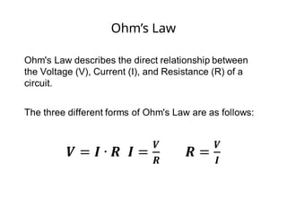
Electrical:
Components, Ohm's Law, Input and Output, Analog and Digital
-----------------------------
Programming:
Split into groups depending on experience
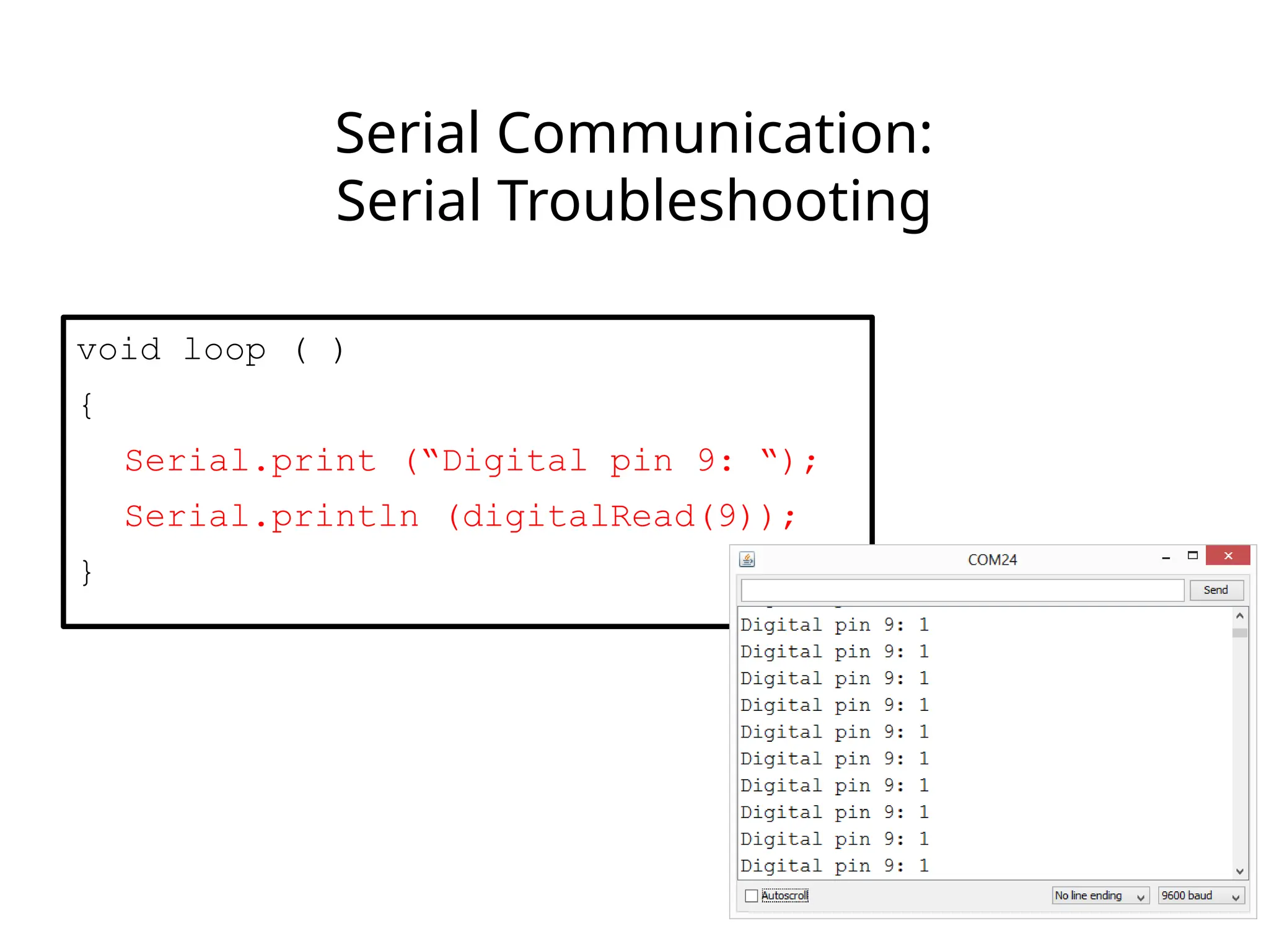
Serial Communication Basics:
Troubleshooting and Debugging
Virtual Prototyping:
Schematics and PCB Layout in Fritzing
6.
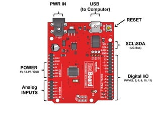
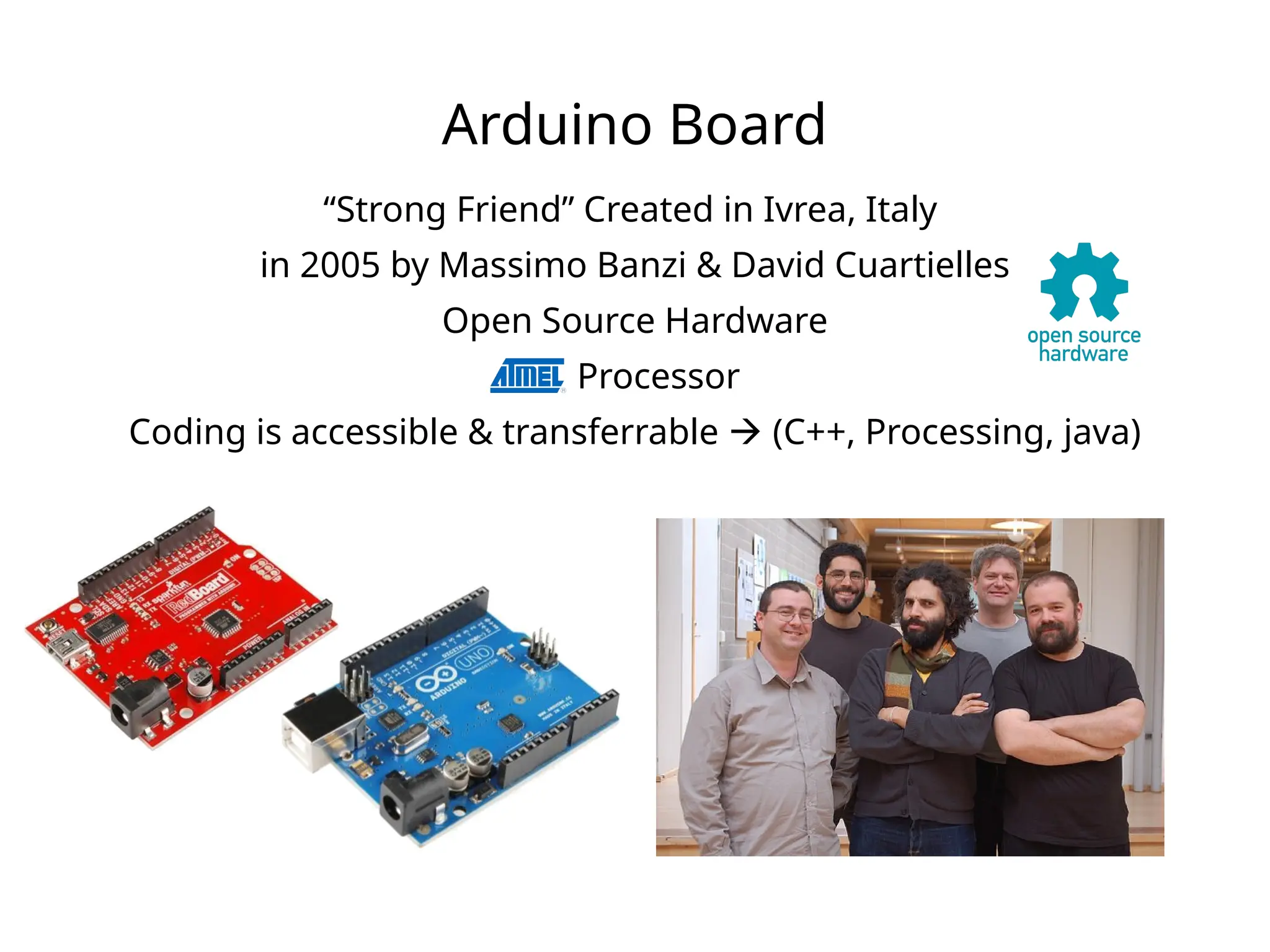
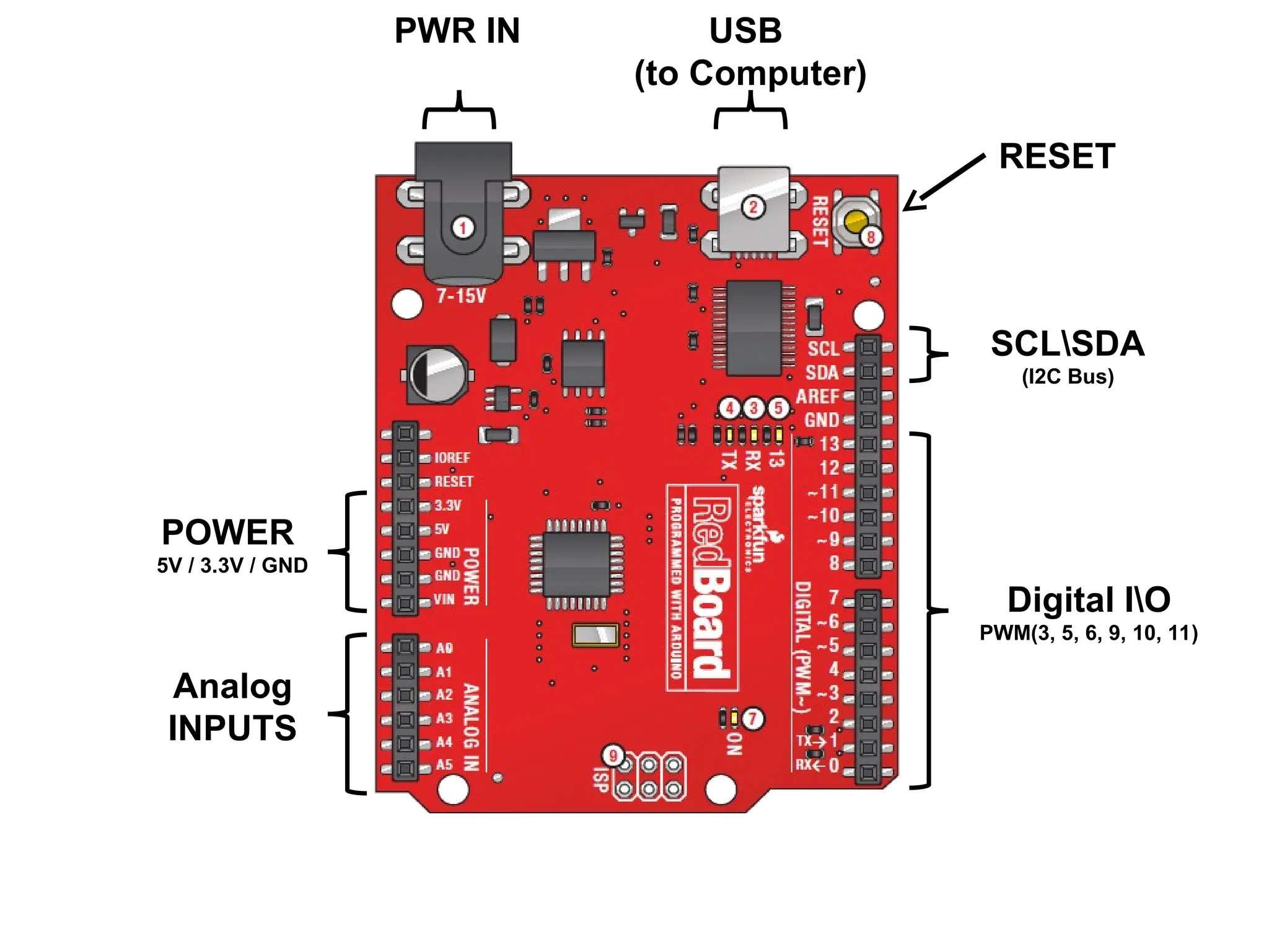
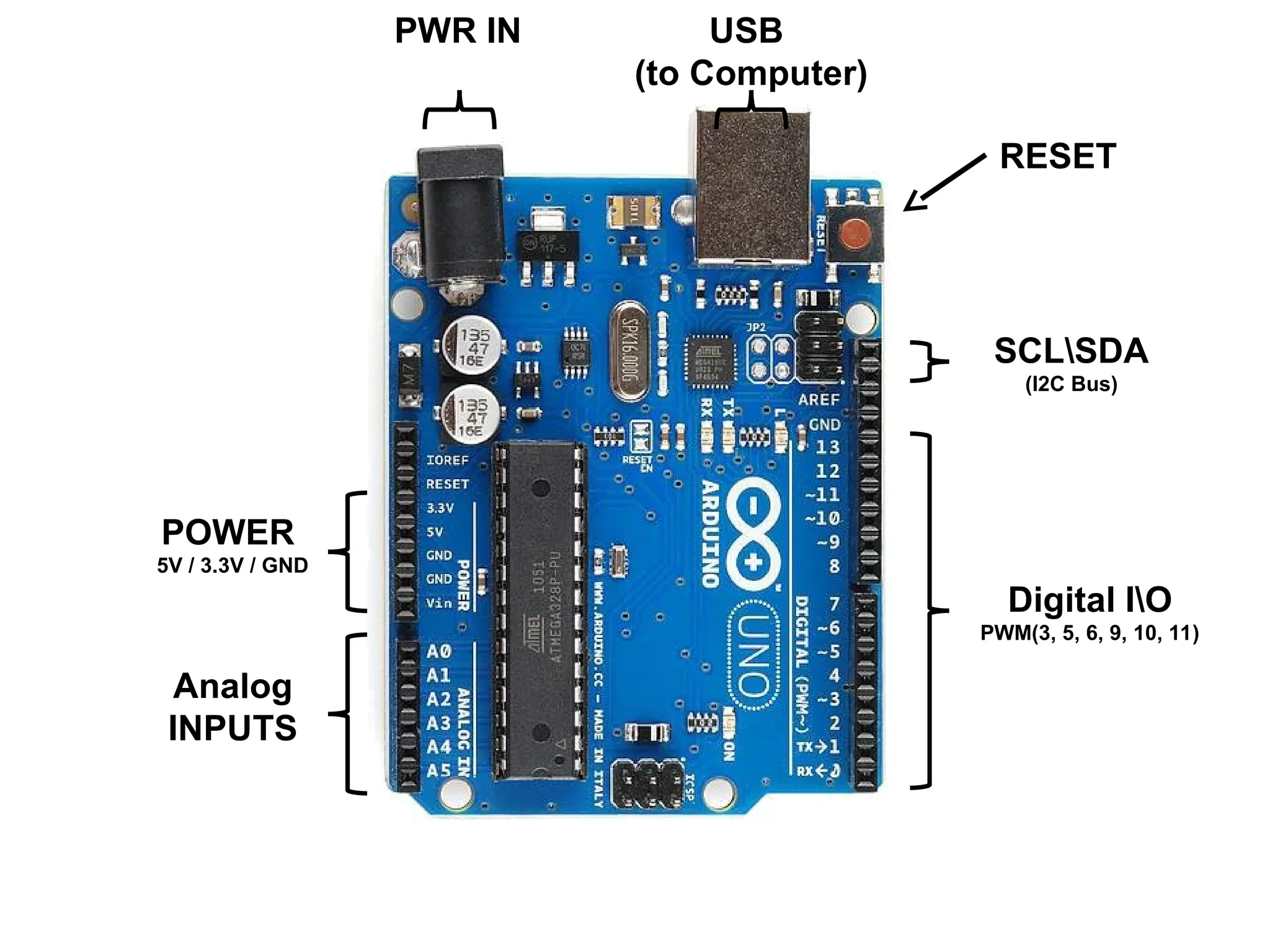
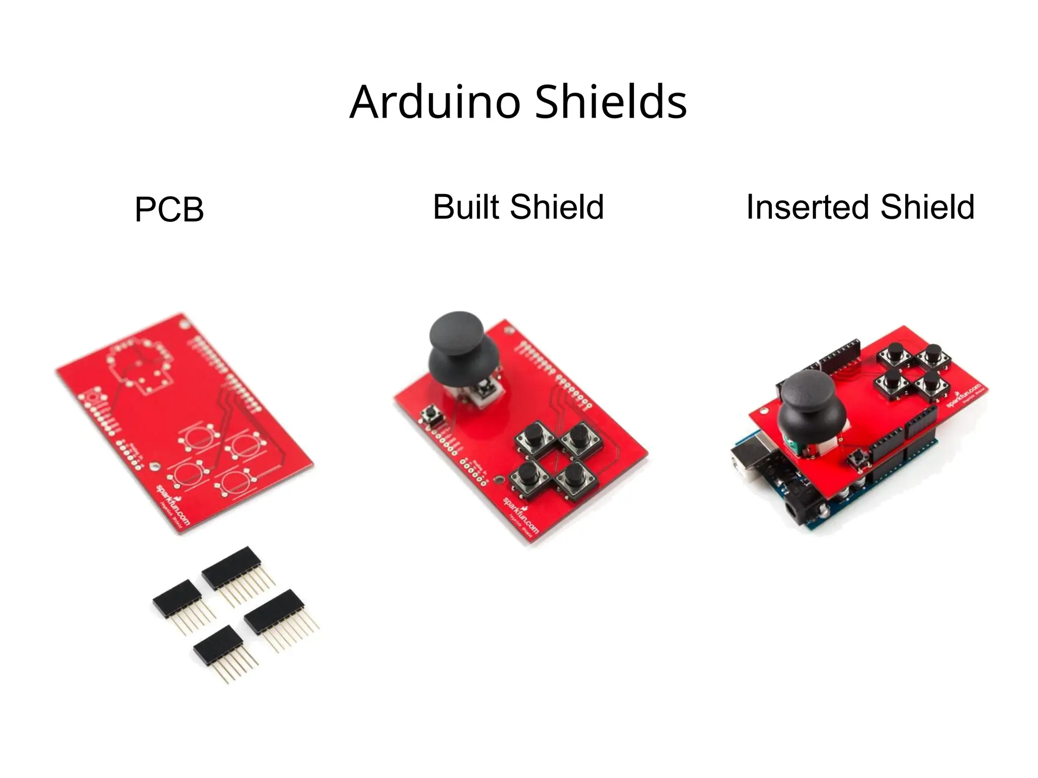
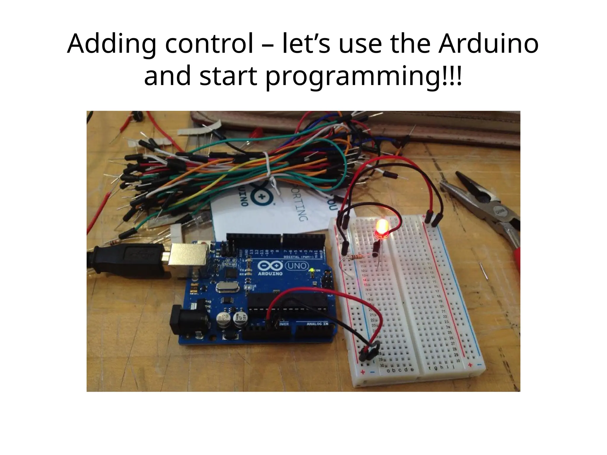
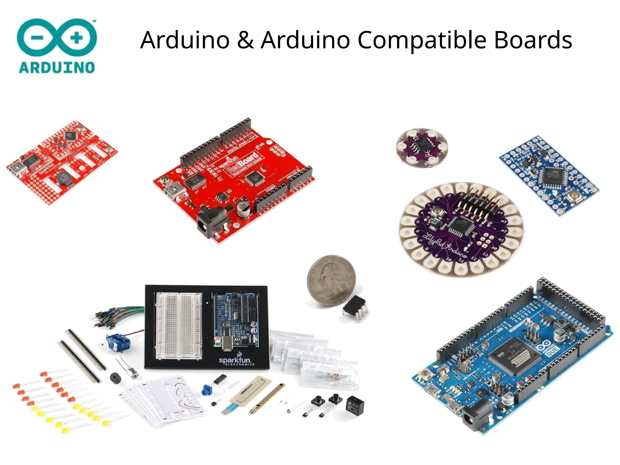
Arduino Board
“Strong Friend”Created in Ivrea, Italy
in 2005 by Massimo Banzi & David Cuartielles
Open Source Hardware
Processor
Coding is accessible & transferrable (C++, Processing, java)
7.
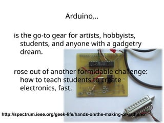
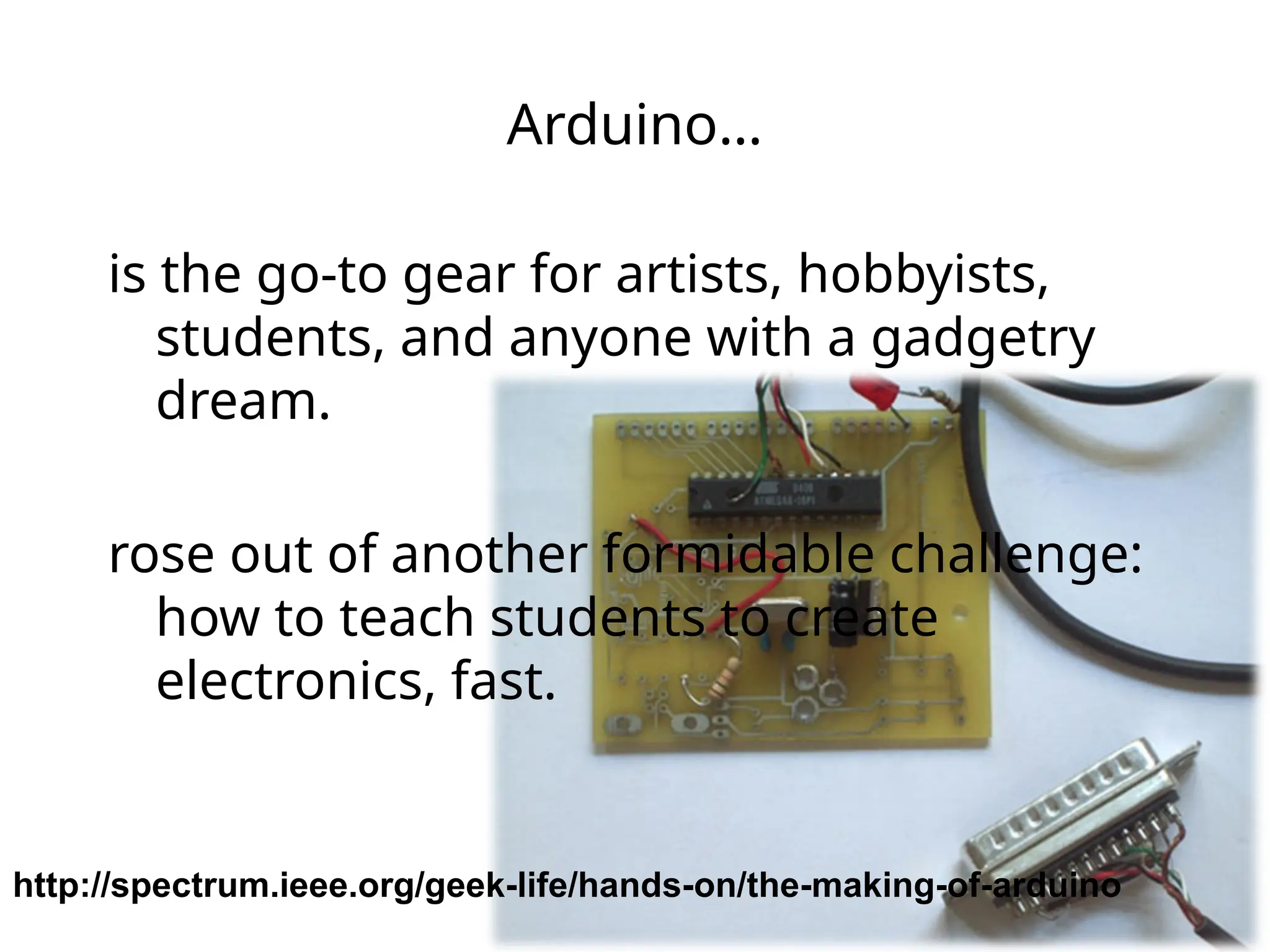
Arduino…
is the go-togear for artists, hobbyists,
students, and anyone with a gadgetry
dream.
rose out of another formidable challenge:
how to teach students to create
electronics, fast.
http://spectrum.ieee.org/geek-life/hands-on/the-making-of-arduino
8.
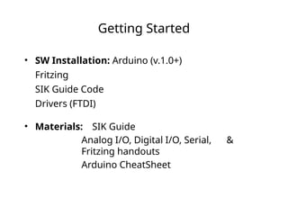
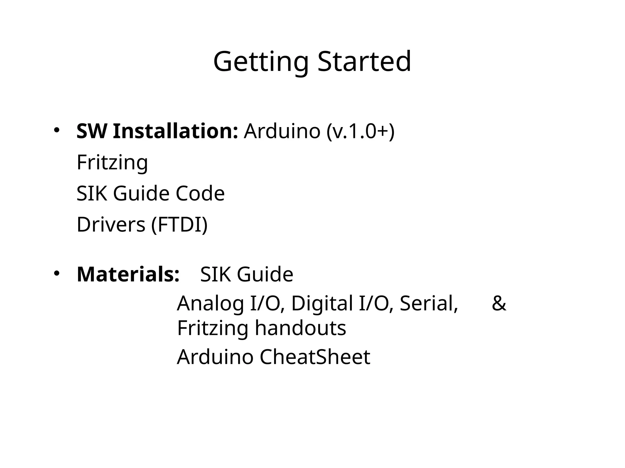
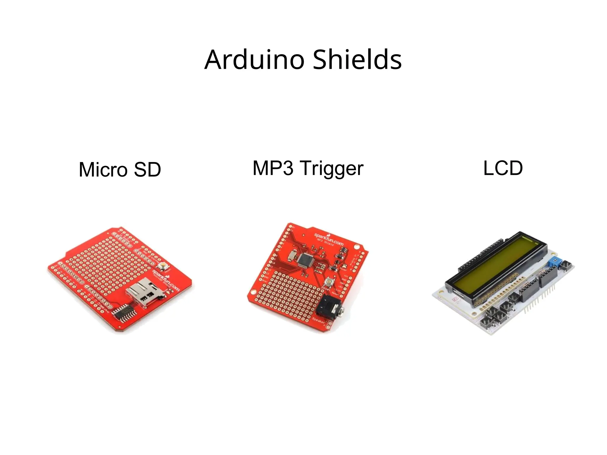
Getting Started
• SWInstallation: Arduino (v.1.0+)
Fritzing
SIK Guide Code
Drivers (FTDI)
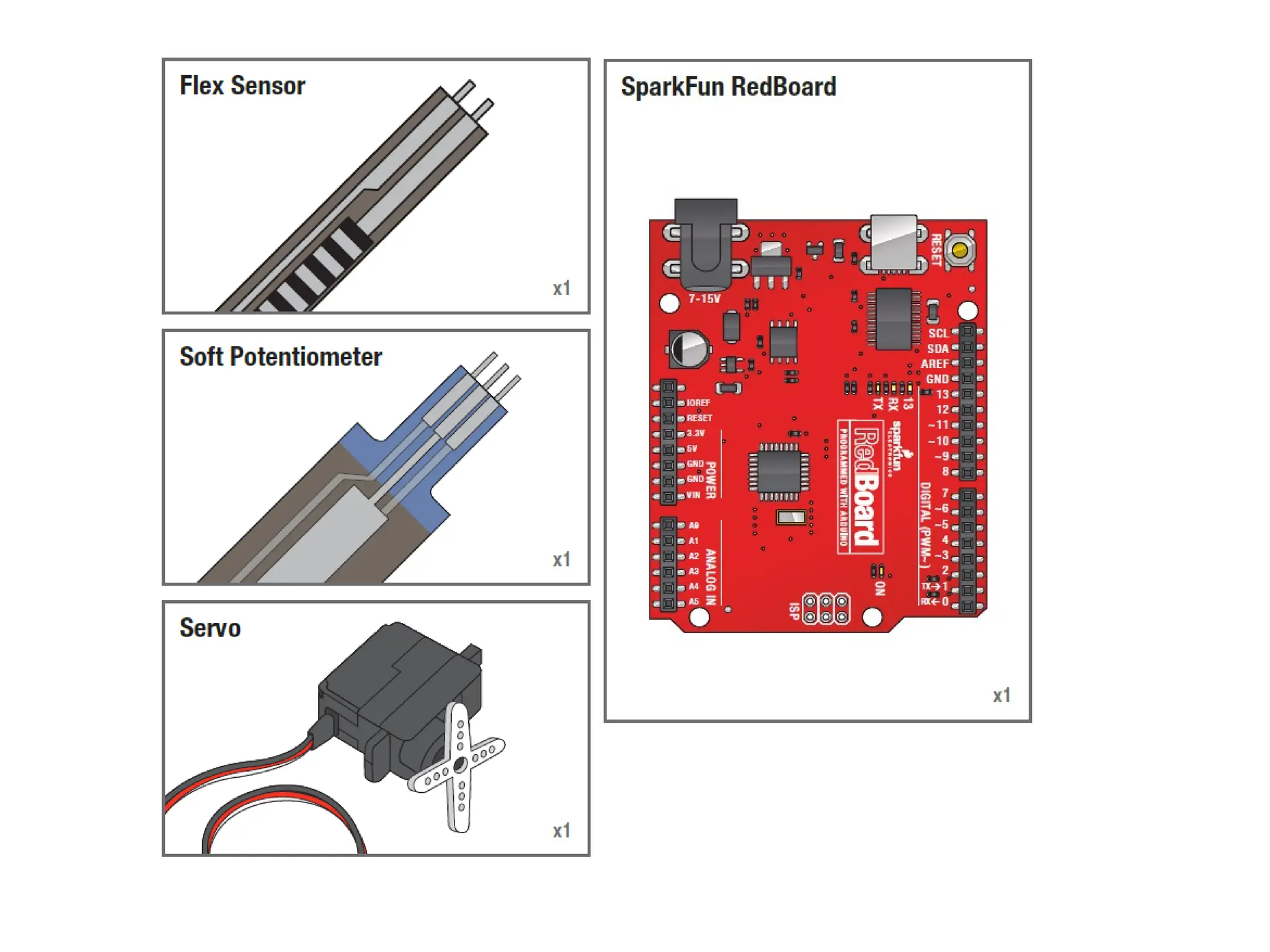
• Materials: SIK Guide
Analog I/O, Digital I/O, Serial, &
Fritzing handouts
Arduino CheatSheet
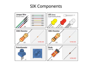
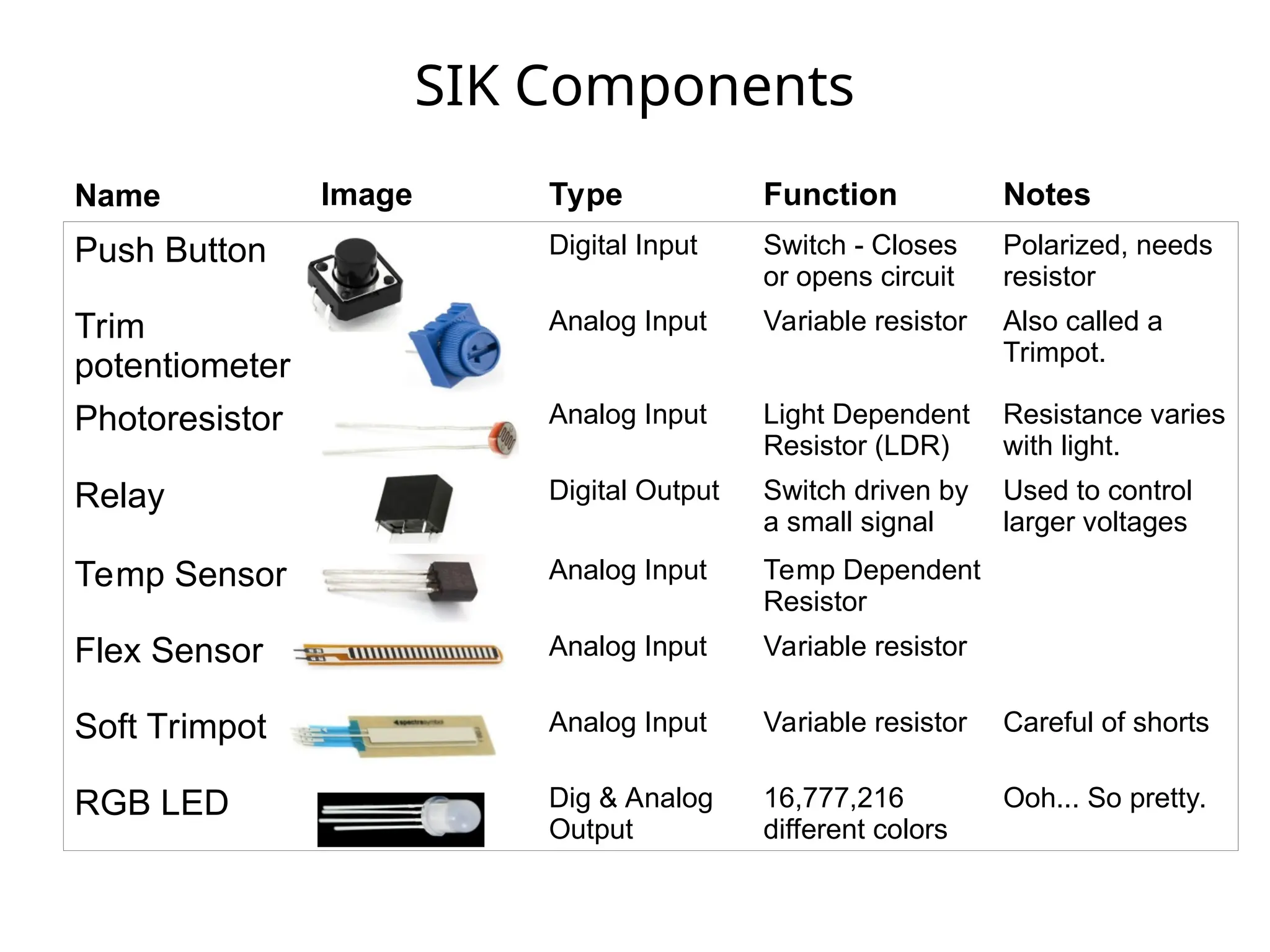
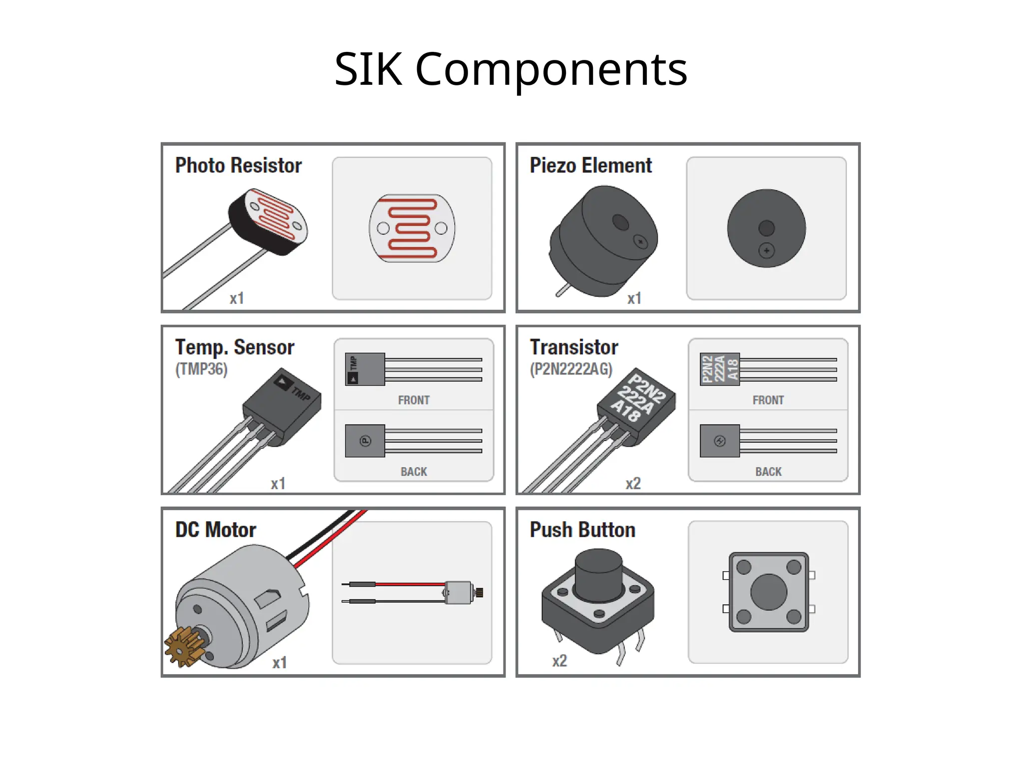
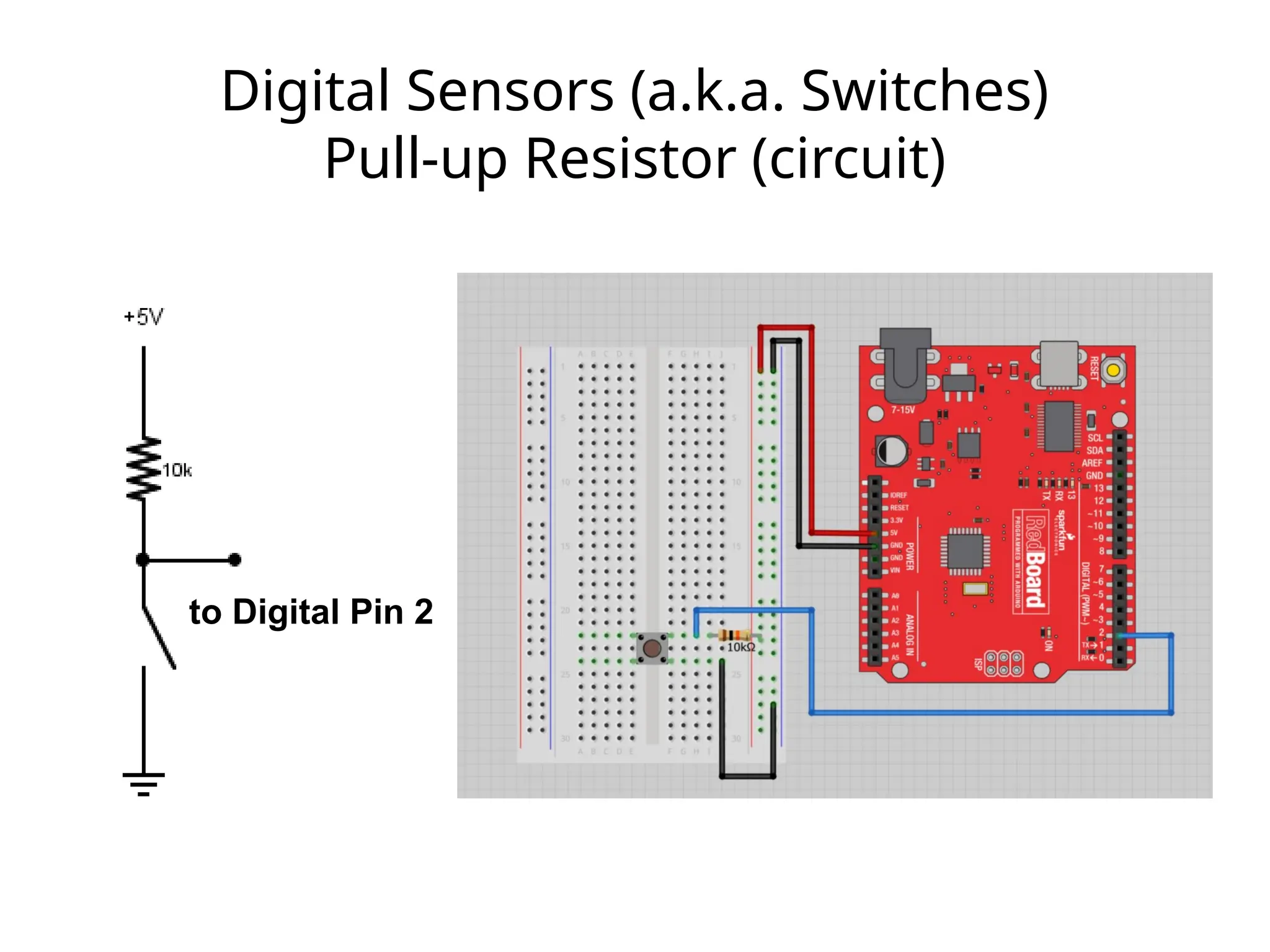
SIK Components
Push ButtonDigital Input Switch - Closes
or opens circuit
Polarized, needs
resistor
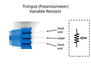
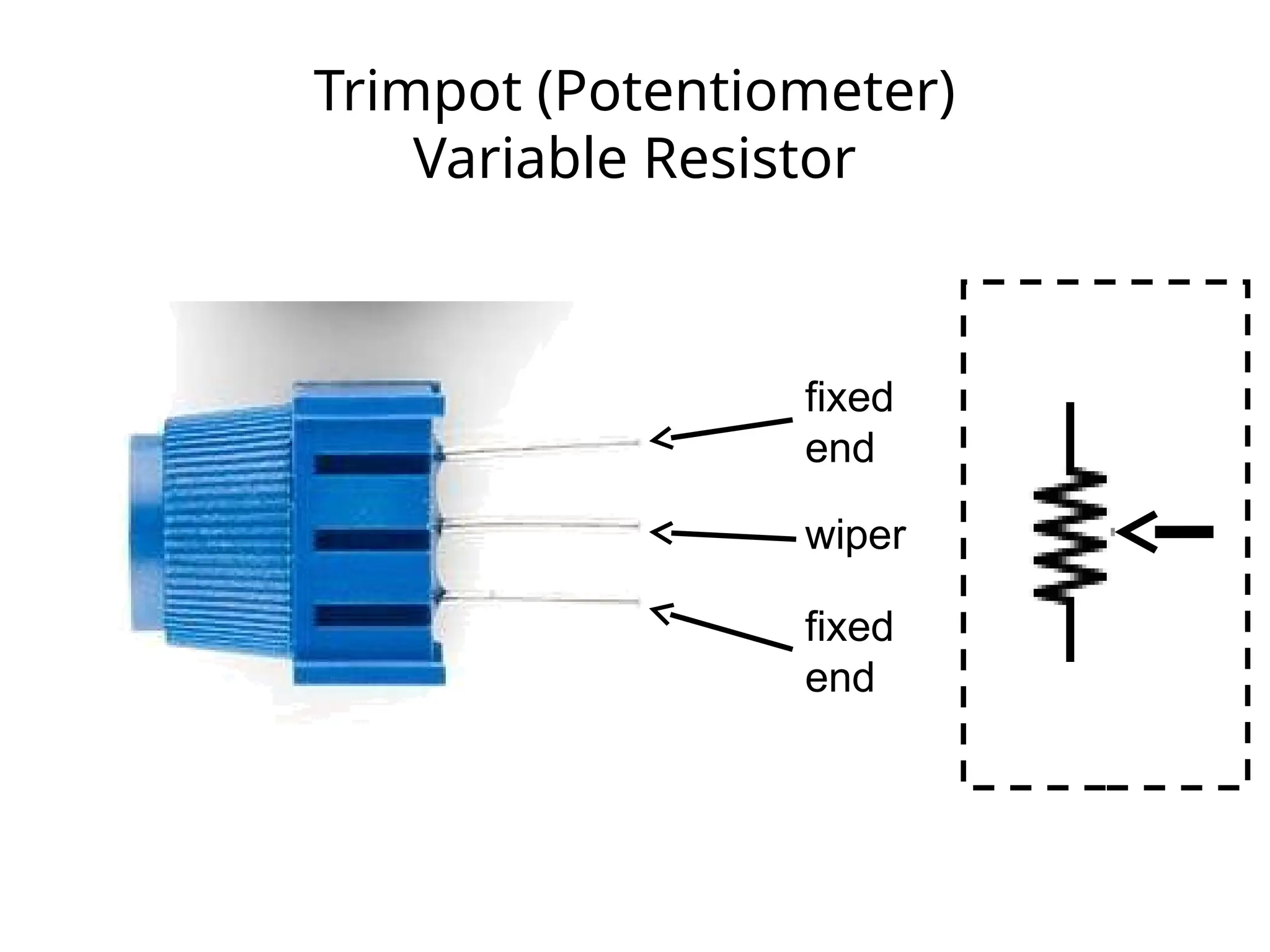
Trim
potentiometer
Analog Input Variable resistor Also called a
Trimpot.
Photoresistor Analog Input Light Dependent
Resistor (LDR)
Resistance varies
with light.
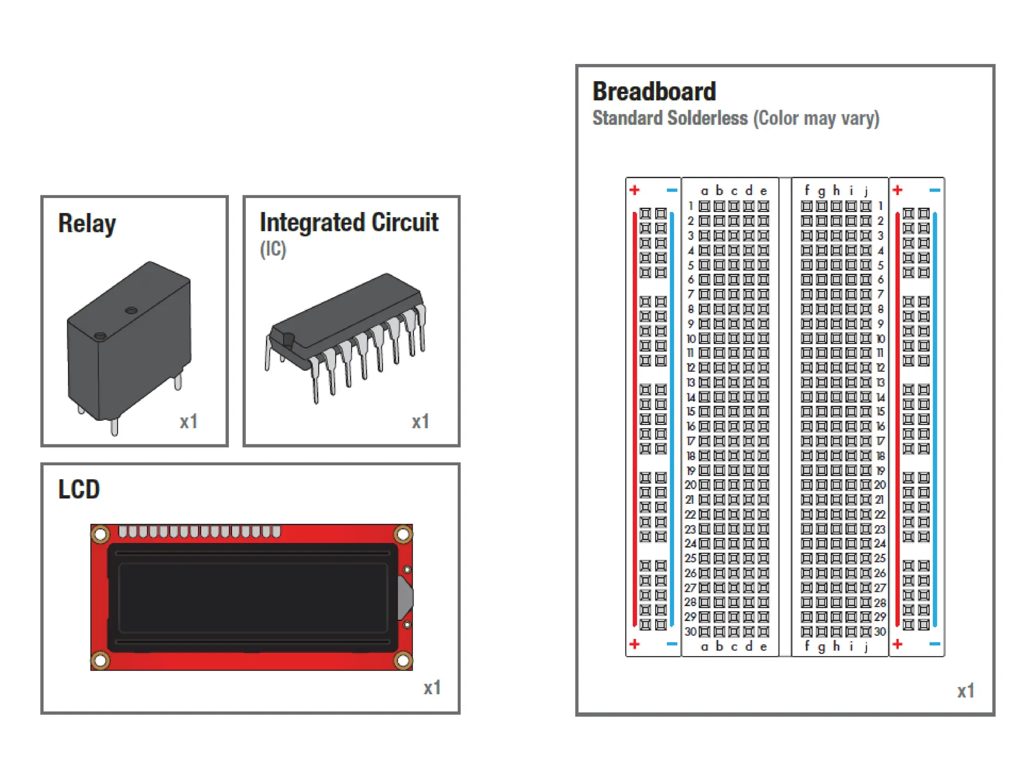
Relay Digital Output Switch driven by
a small signal
Used to control
larger voltages
Temp Sensor Analog Input Temp Dependent
Resistor
Flex Sensor Analog Input Variable resistor
Soft Trimpot Analog Input Variable resistor Careful of shorts
RGB LED Dig & Analog
Output
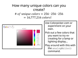
16,777,216
different colors
Ooh... So pretty.
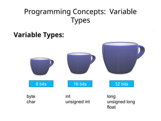
Name Image Type Function Notes
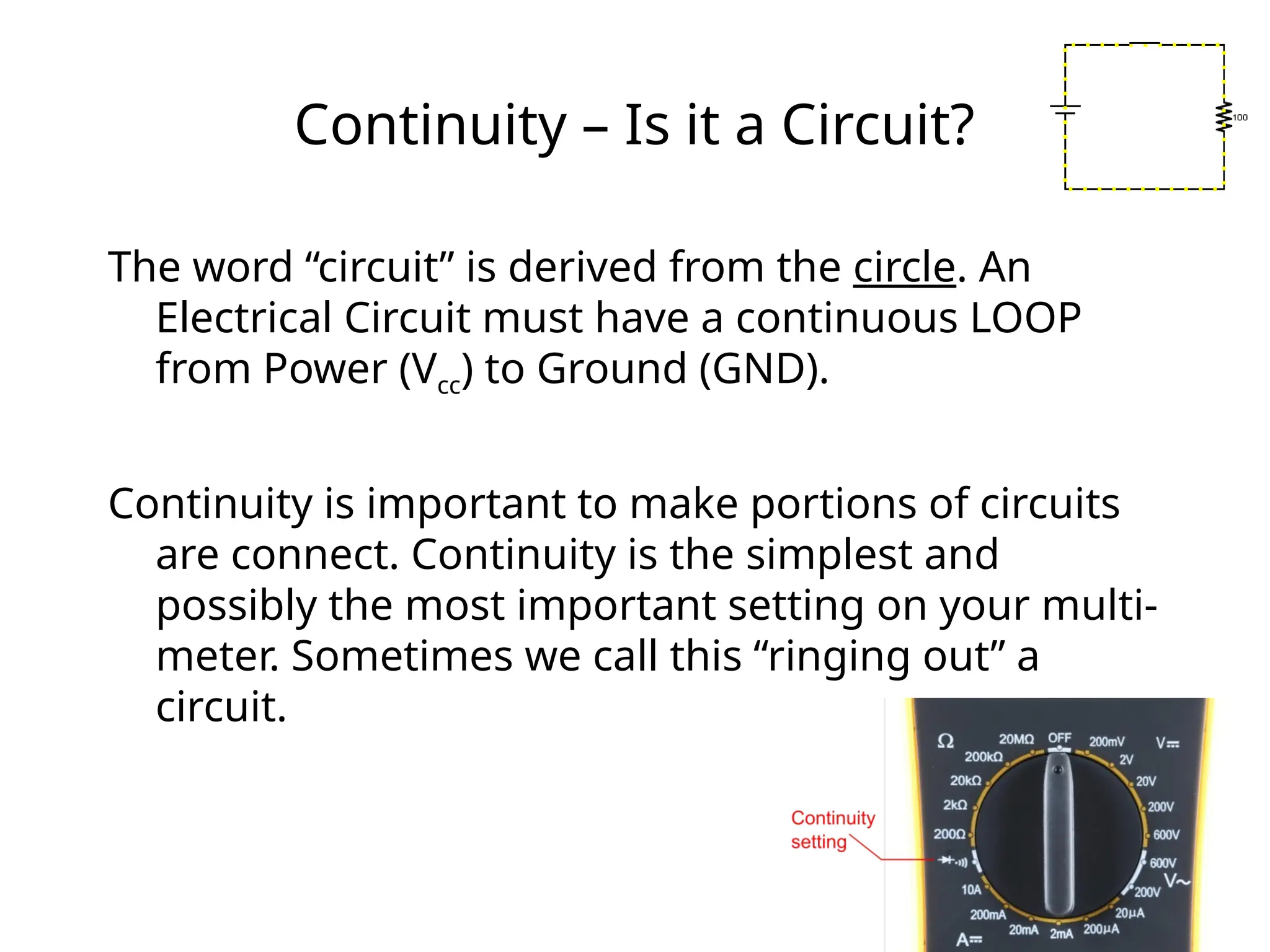
Continuity – Isit a Circuit?
The word “circuit” is derived from the circle. An
Electrical Circuit must have a continuous LOOP
from Power (Vcc) to Ground (GND).
Continuity is important to make portions of circuits
are connect. Continuity is the simplest and
possibly the most important setting on your multi-
meter. Sometimes we call this “ringing out” a
circuit.
26.
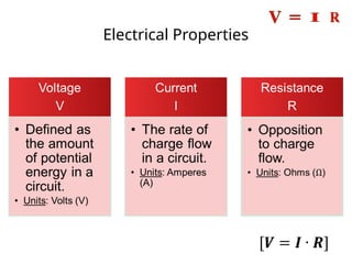
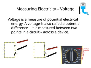
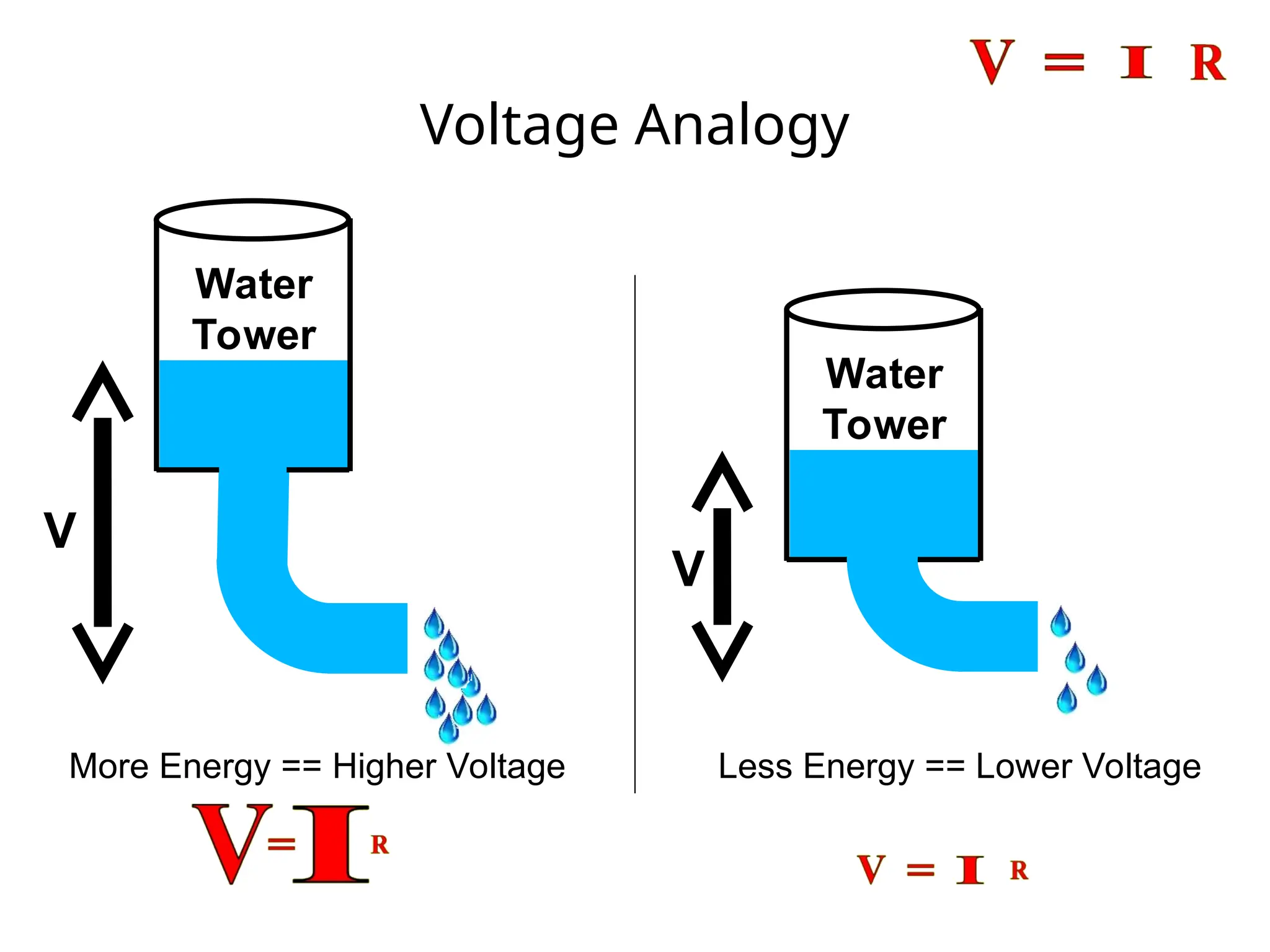
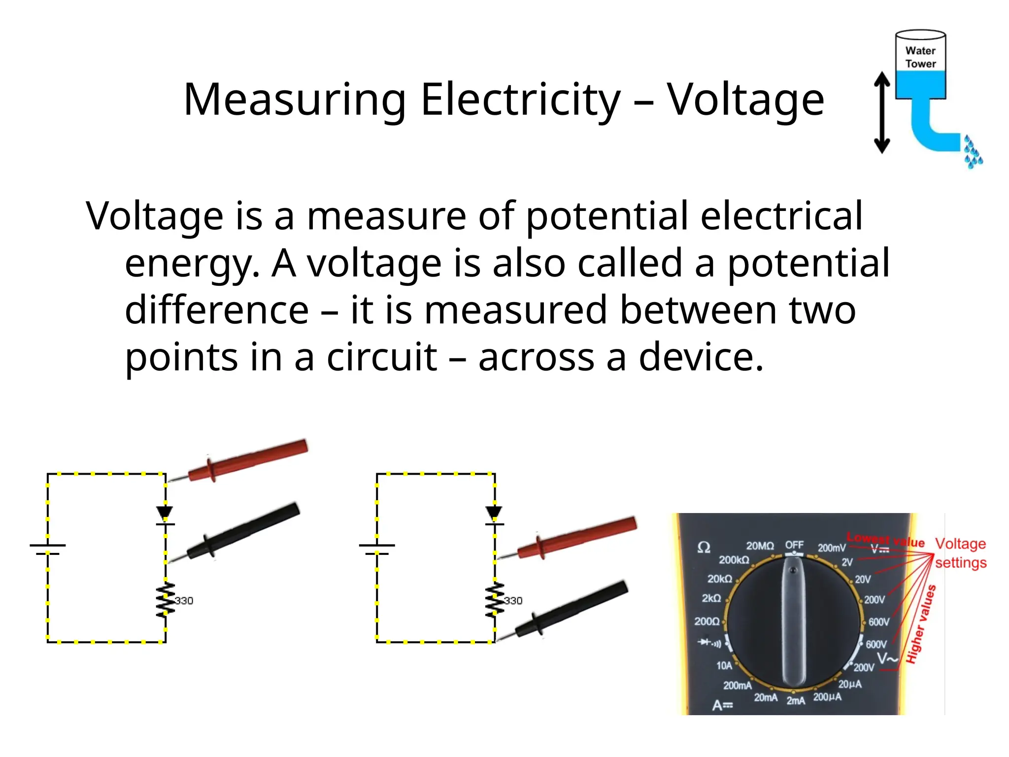
Measuring Electricity –Voltage
Voltage is a measure of potential electrical
energy. A voltage is also called a potential
difference – it is measured between two
points in a circuit – across a device.
27.
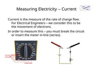
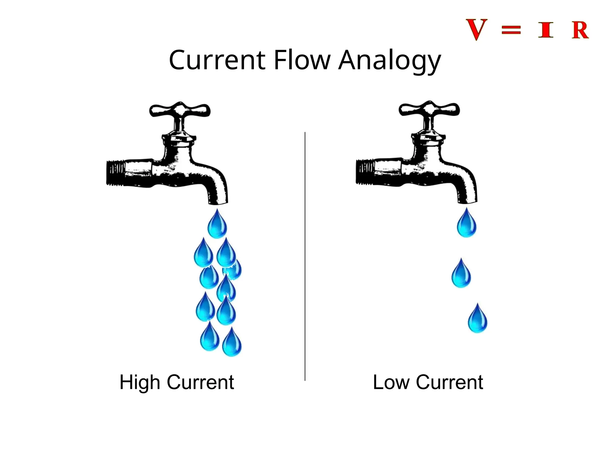
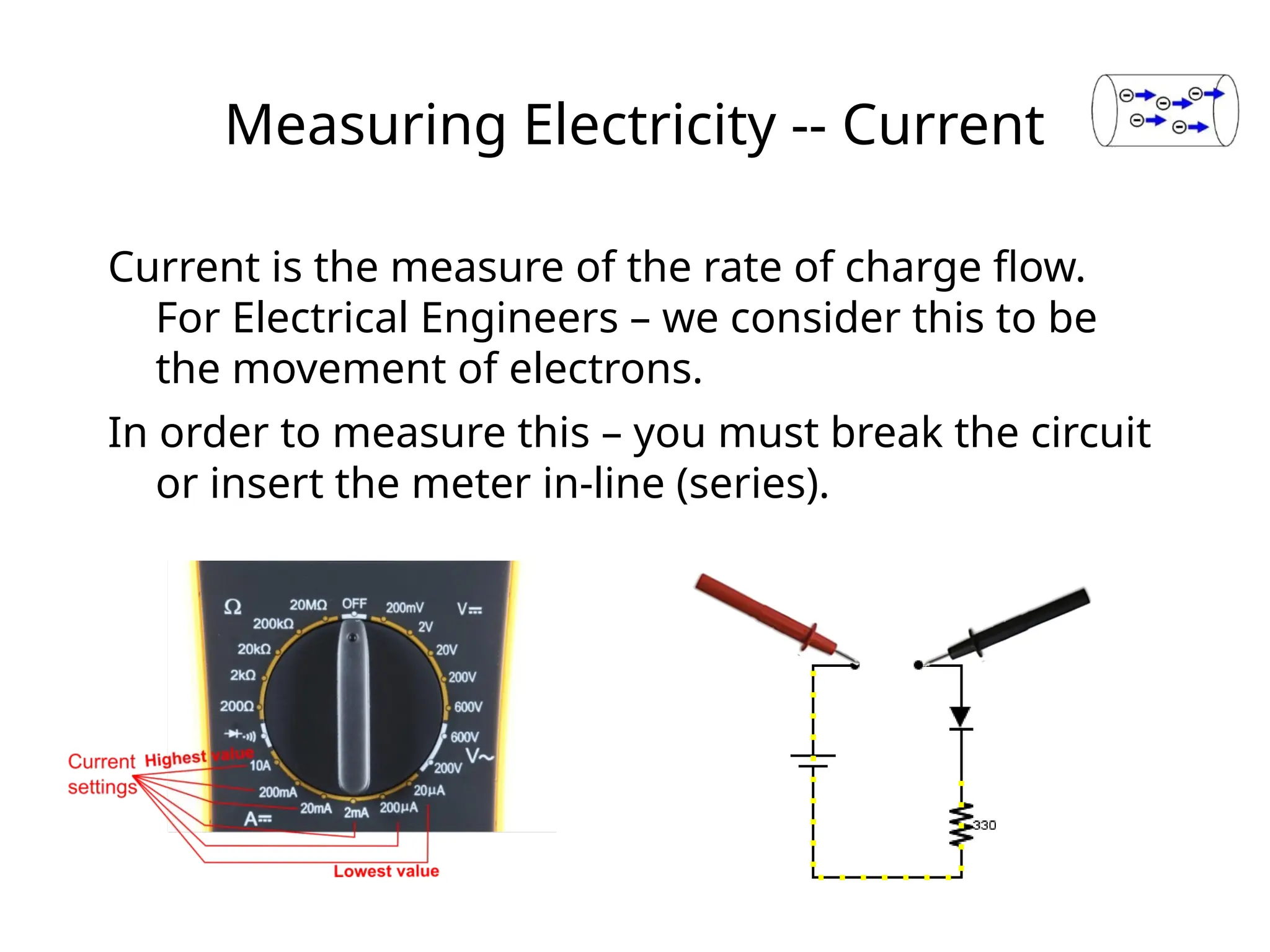
Measuring Electricity --Current
Current is the measure of the rate of charge flow.
For Electrical Engineers – we consider this to be
the movement of electrons.
In order to measure this – you must break the circuit
or insert the meter in-line (series).
28.
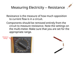
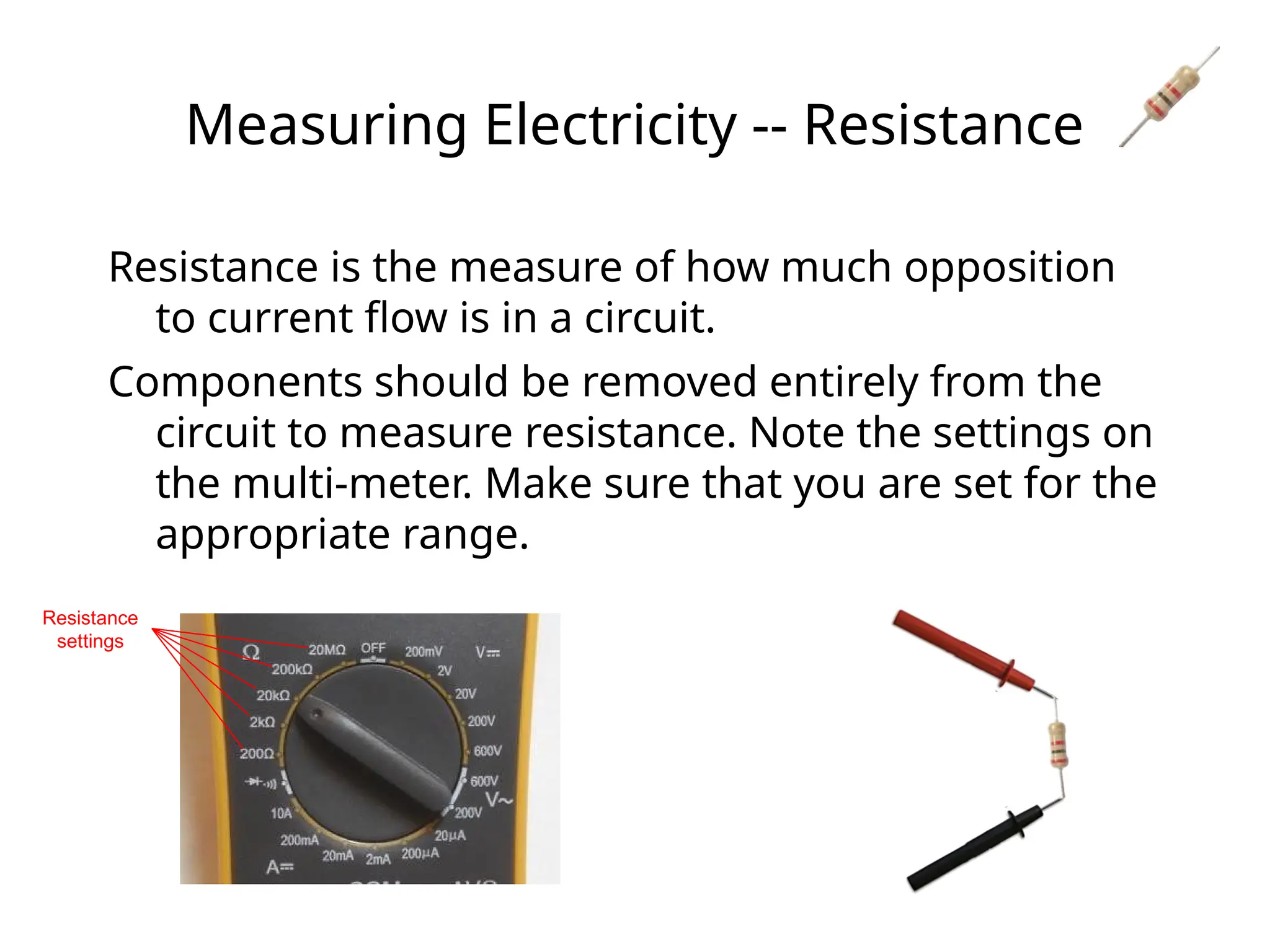
Measuring Electricity --Resistance
Resistance is the measure of how much opposition
to current flow is in a circuit.
Components should be removed entirely from the
circuit to measure resistance. Note the settings on
the multi-meter. Make sure that you are set for the
appropriate range.
Resistance
settings
29.
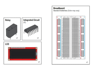
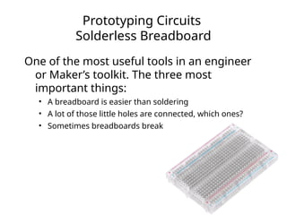
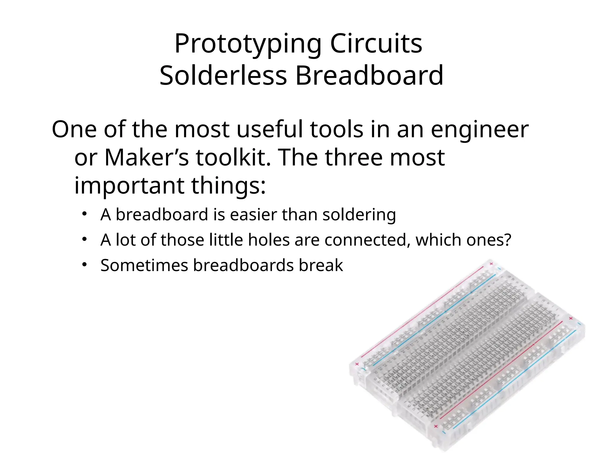
Prototyping Circuits
Solderless Breadboard
Oneof the most useful tools in an engineer
or Maker’s toolkit. The three most
important things:
• A breadboard is easier than soldering
• A lot of those little holes are connected, which ones?
• Sometimes breadboards break
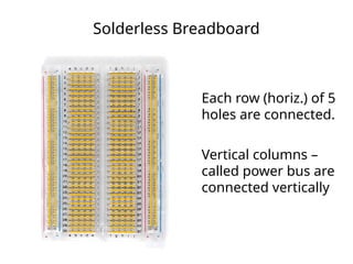
Solderless Breadboard
Each row(horiz.) of 5
holes are connected.
Vertical columns –
called power bus are
connected vertically
32.
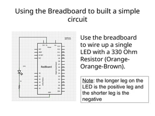
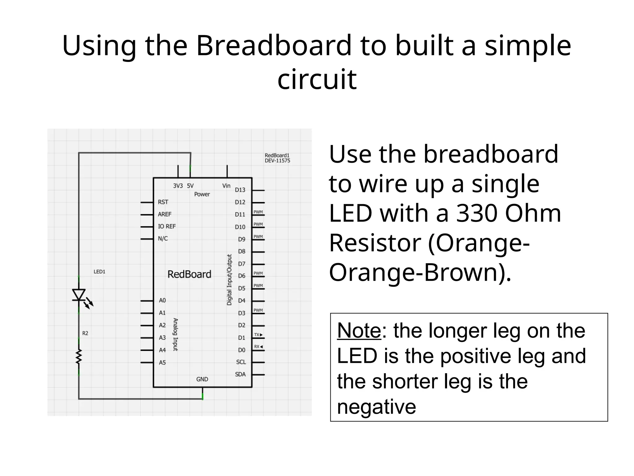
Using the Breadboardto built a simple
circuit
Use the breadboard
to wire up a single
LED with a 330 Ohm
Resistor (Orange-
Orange-Brown).
Note: the longer leg on the
LED is the positive leg and
the shorter leg is the
negative
33.
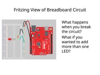
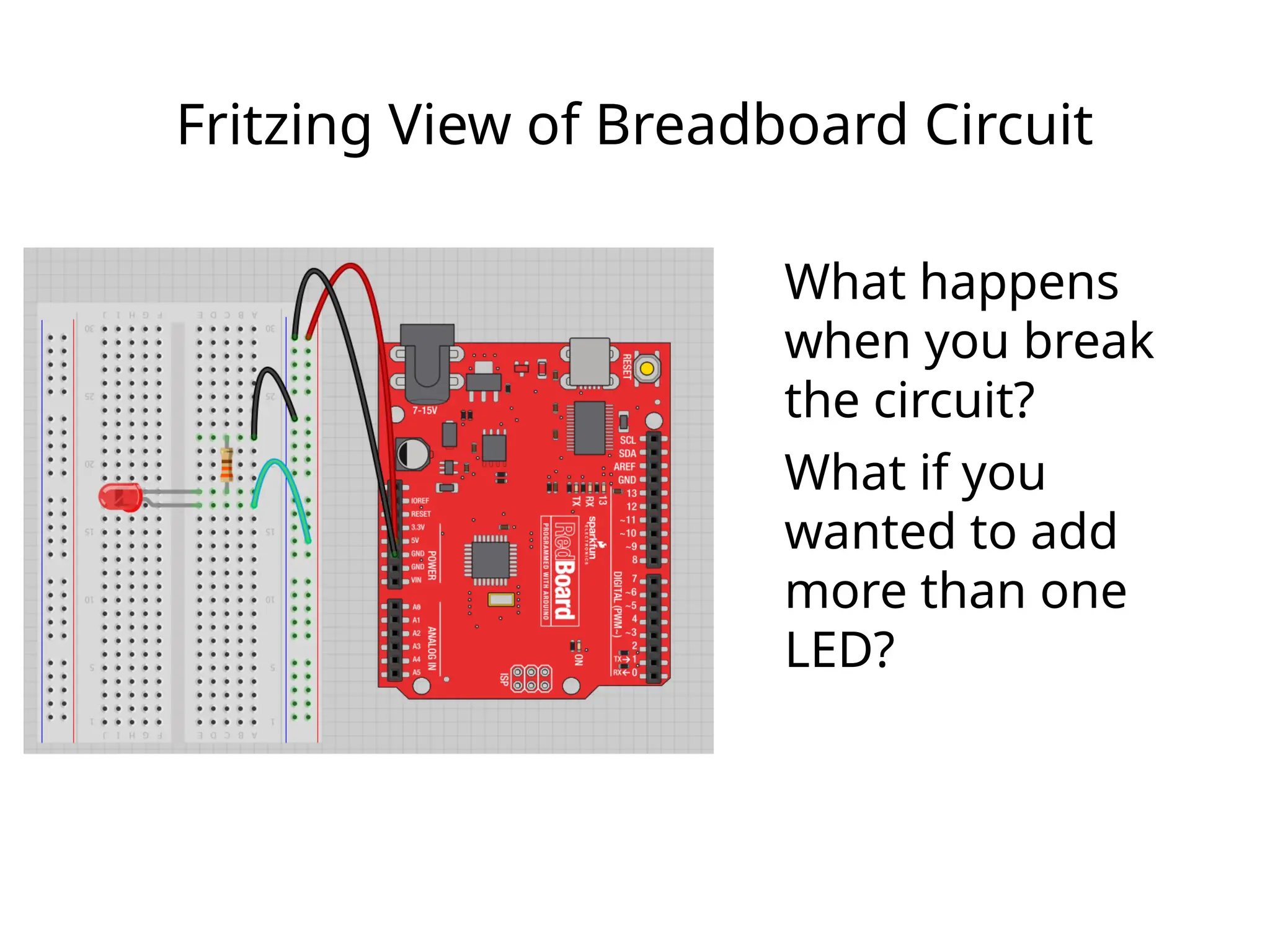
Fritzing View ofBreadboard Circuit
What happens
when you break
the circuit?
What if you
wanted to add
more than one
LED?
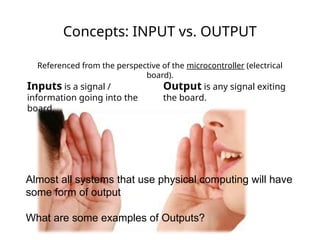
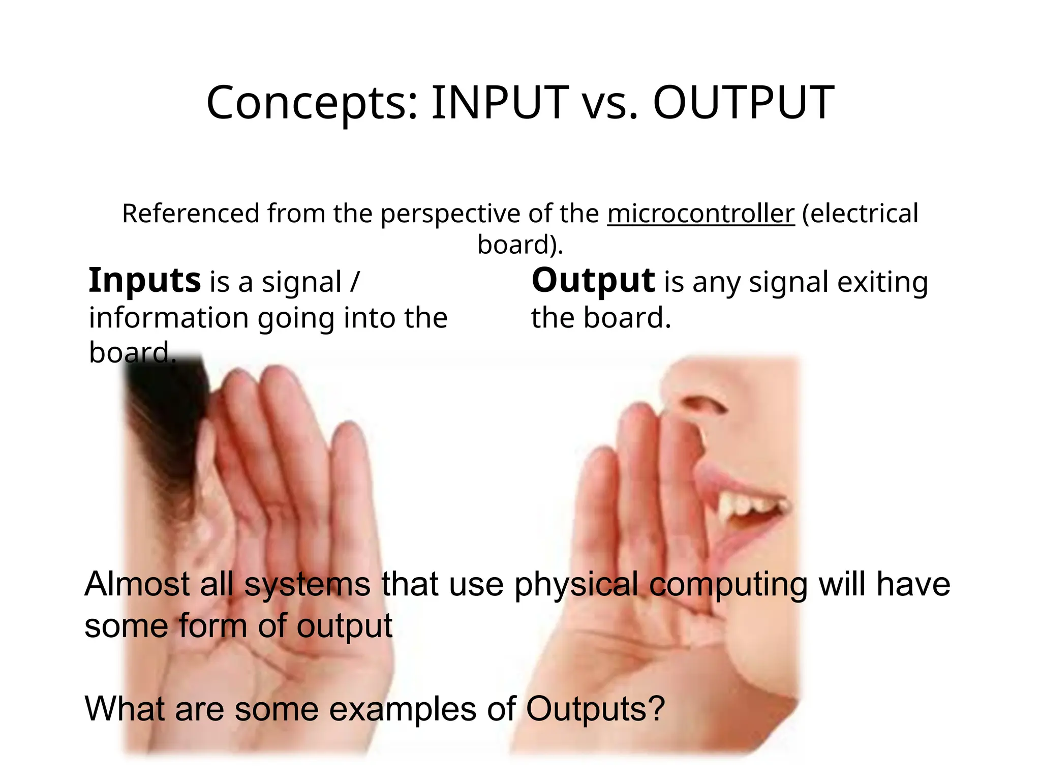
Concepts: INPUT vs.OUTPUT
Referenced from the perspective of the microcontroller (electrical
board).
Inputs is a signal /
information going into the
board.
Output is any signal exiting
the board.
Almost all systems that use physical computing will have
some form of output
What are some examples of Outputs?
36.
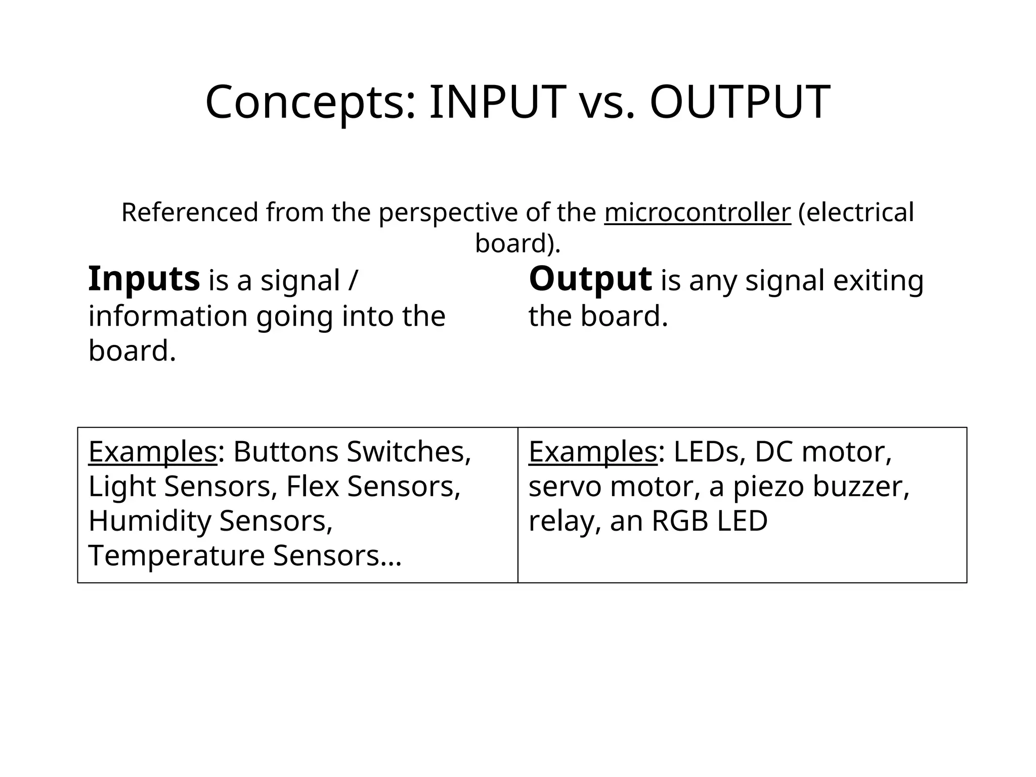
Concepts: INPUT vs.OUTPUT
Referenced from the perspective of the microcontroller (electrical
board).
Inputs is a signal /
information going into the
board.
Output is any signal exiting
the board.
Examples: Buttons Switches,
Light Sensors, Flex Sensors,
Humidity Sensors,
Temperature Sensors…
Examples: LEDs, DC motor,
servo motor, a piezo buzzer,
relay, an RGB LED
37.
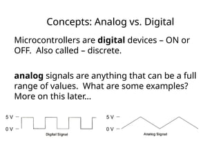
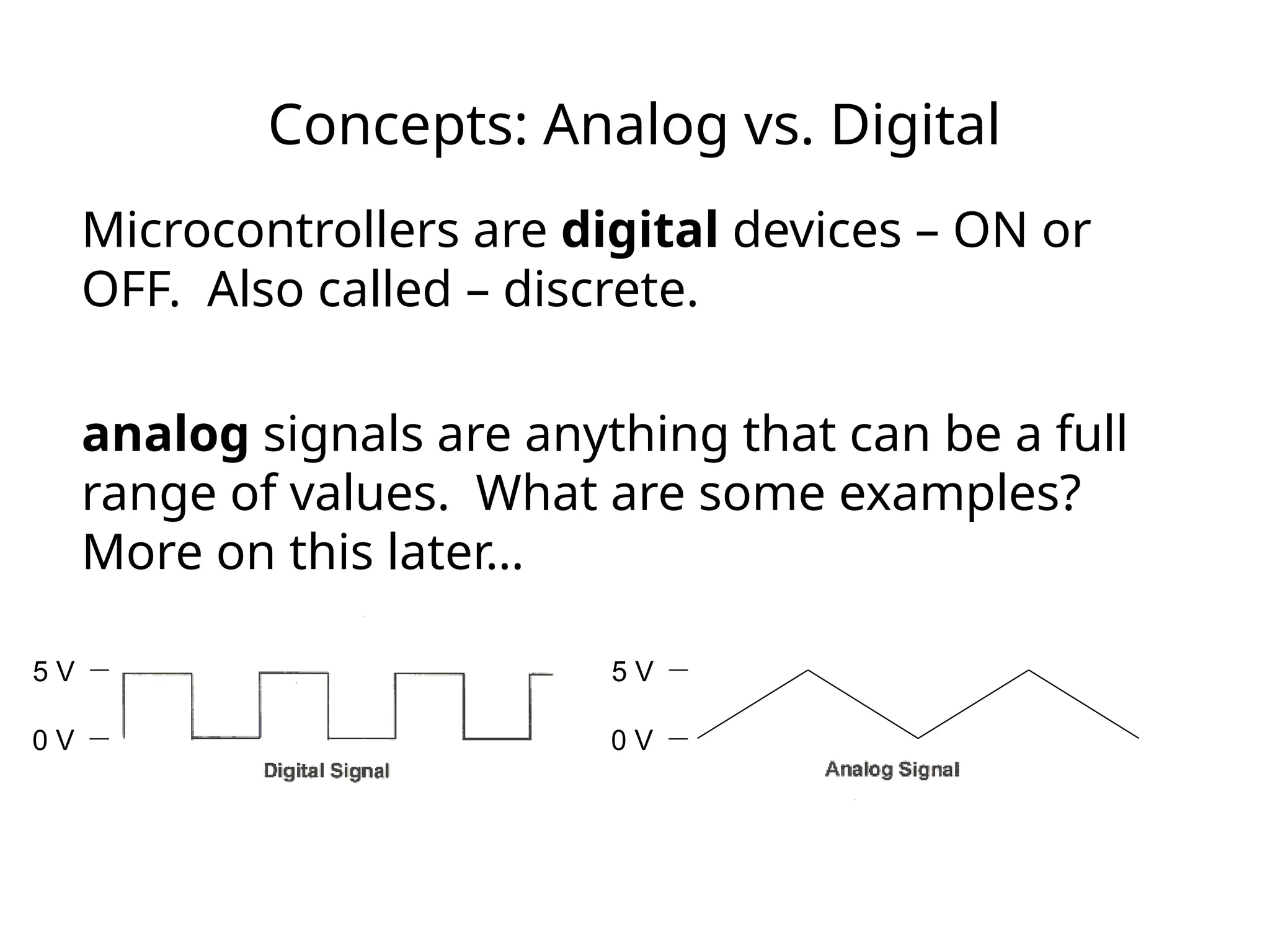
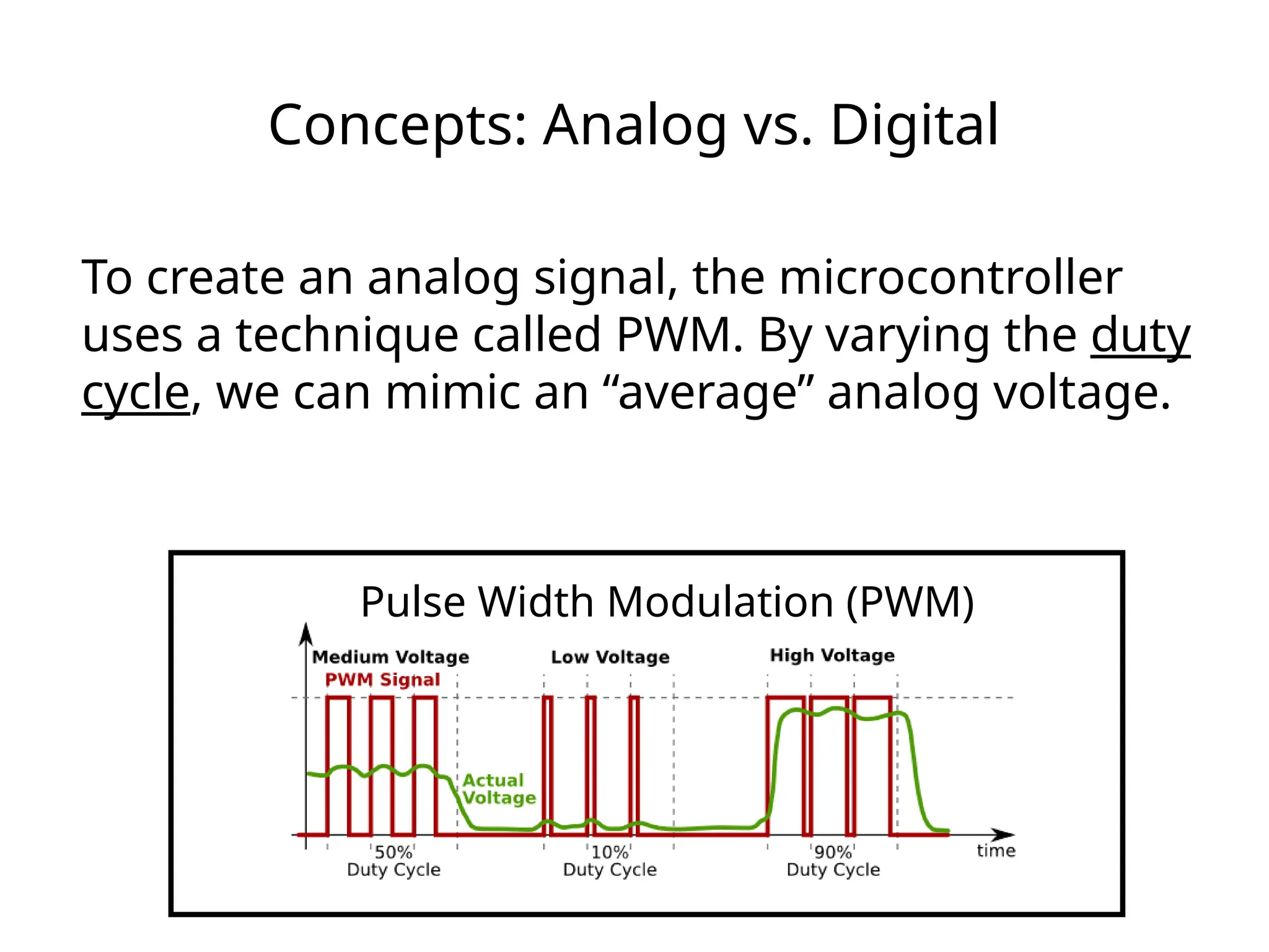
Concepts: Analog vs.Digital
Microcontrollers are digital devices – ON or
OFF. Also called – discrete.
analog signals are anything that can be a full
range of values. What are some examples?
More on this later…
5 V
0 V
5 V
0 V
38.
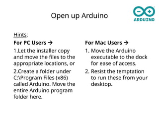
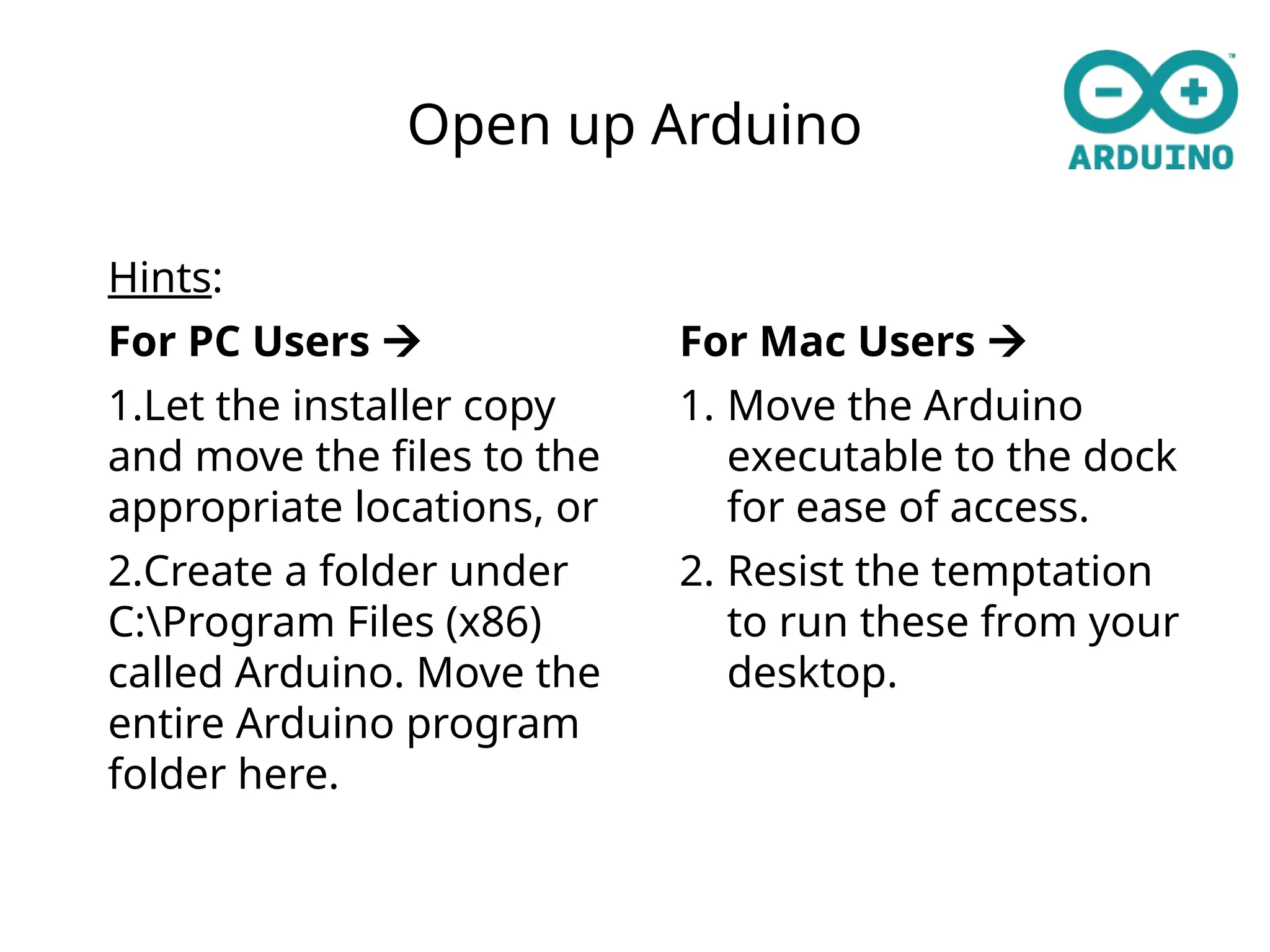
Open up Arduino
Hints:
ForPC Users
1.Let the installer copy
and move the files to the
appropriate locations, or
2.Create a folder under
C:Program Files (x86)
called Arduino. Move the
entire Arduino program
folder here.
For Mac Users
1. Move the Arduino
executable to the dock
for ease of access.
2. Resist the temptation
to run these from your
desktop.
39.
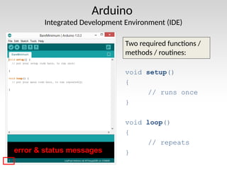
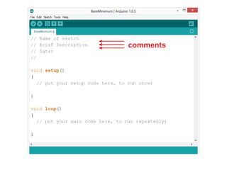
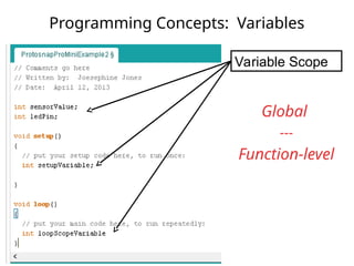
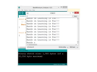
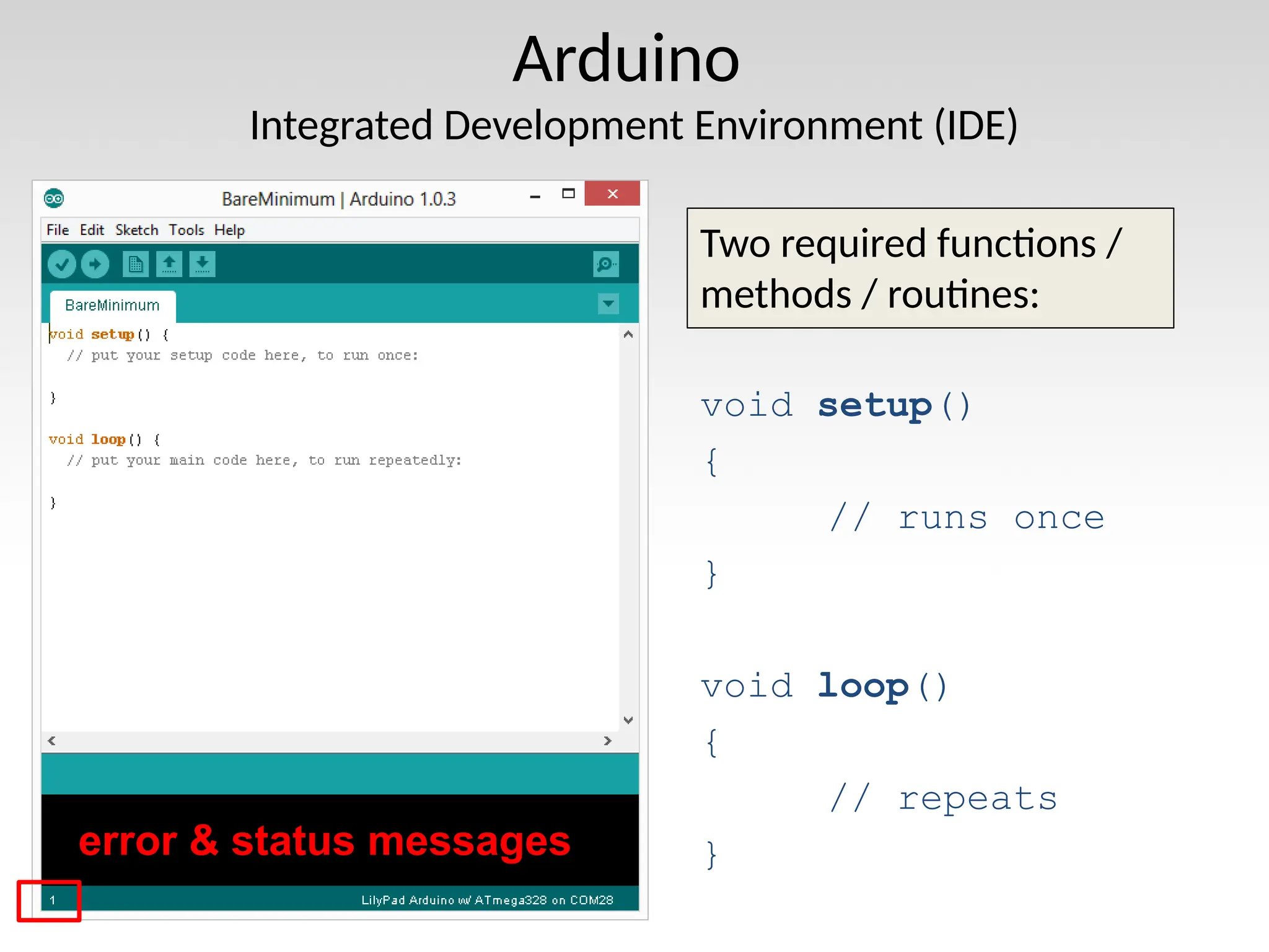
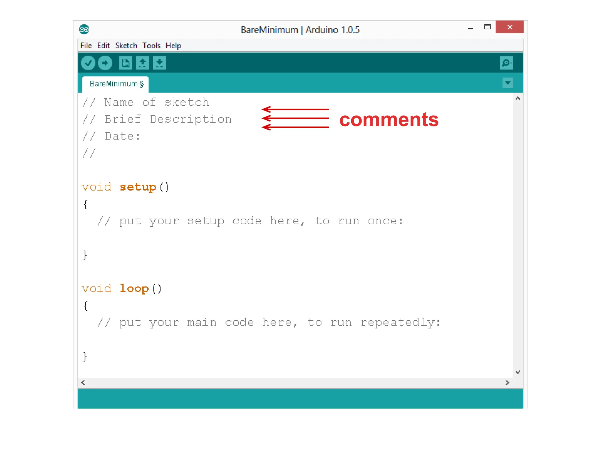
Arduino
Integrated Development Environment(IDE)
Two required functions /
methods / routines:
void setup()
{
// runs once
}
void loop()
{
// repeats
}
error & status messages
40.
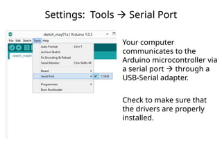
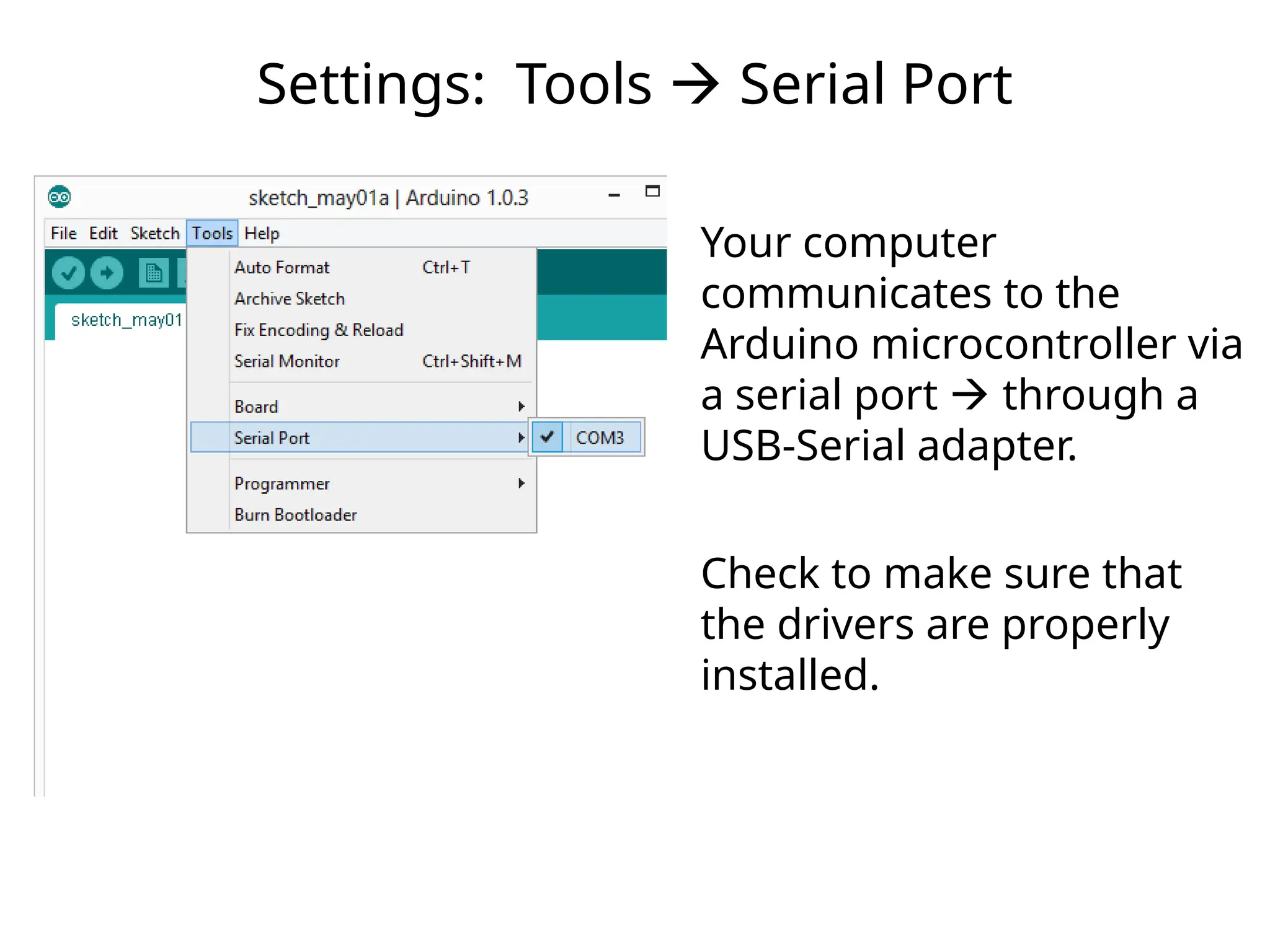
Settings: Tools Serial Port
Your computer
communicates to the
Arduino microcontroller via
a serial port through a
USB-Serial adapter.
Check to make sure that
the drivers are properly
installed.
41.
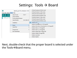
Settings: Tools Board
Next, double-check that the proper board is selected under
the ToolsBoard menu.
This work islicensed under a Creative Commons Attribution-ShareAlike 3.0 United States License.
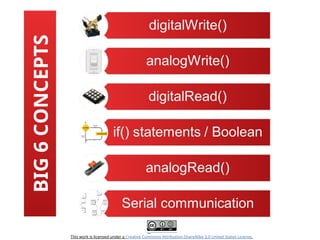
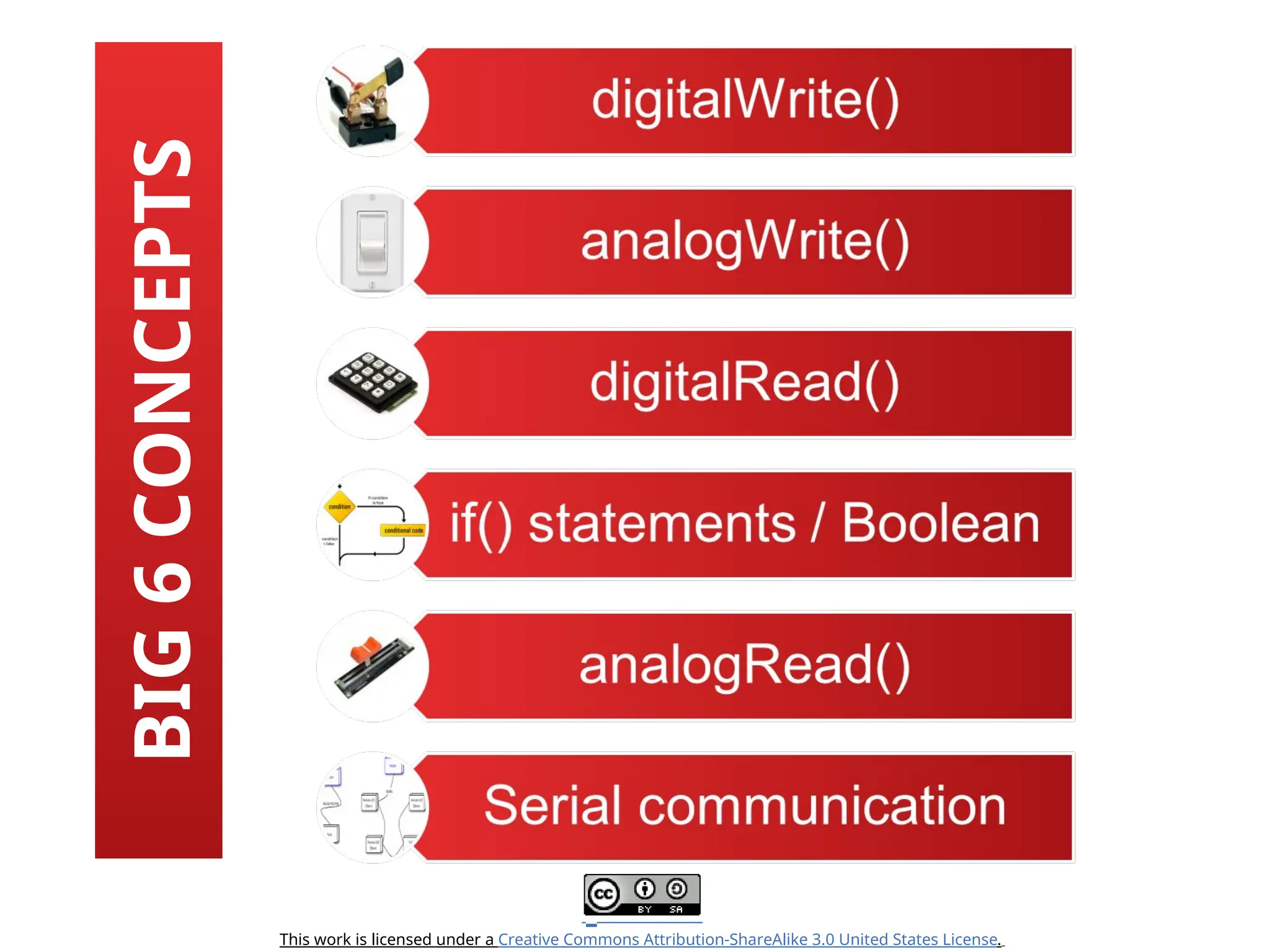
BIG
6
CONCEPTS
44.
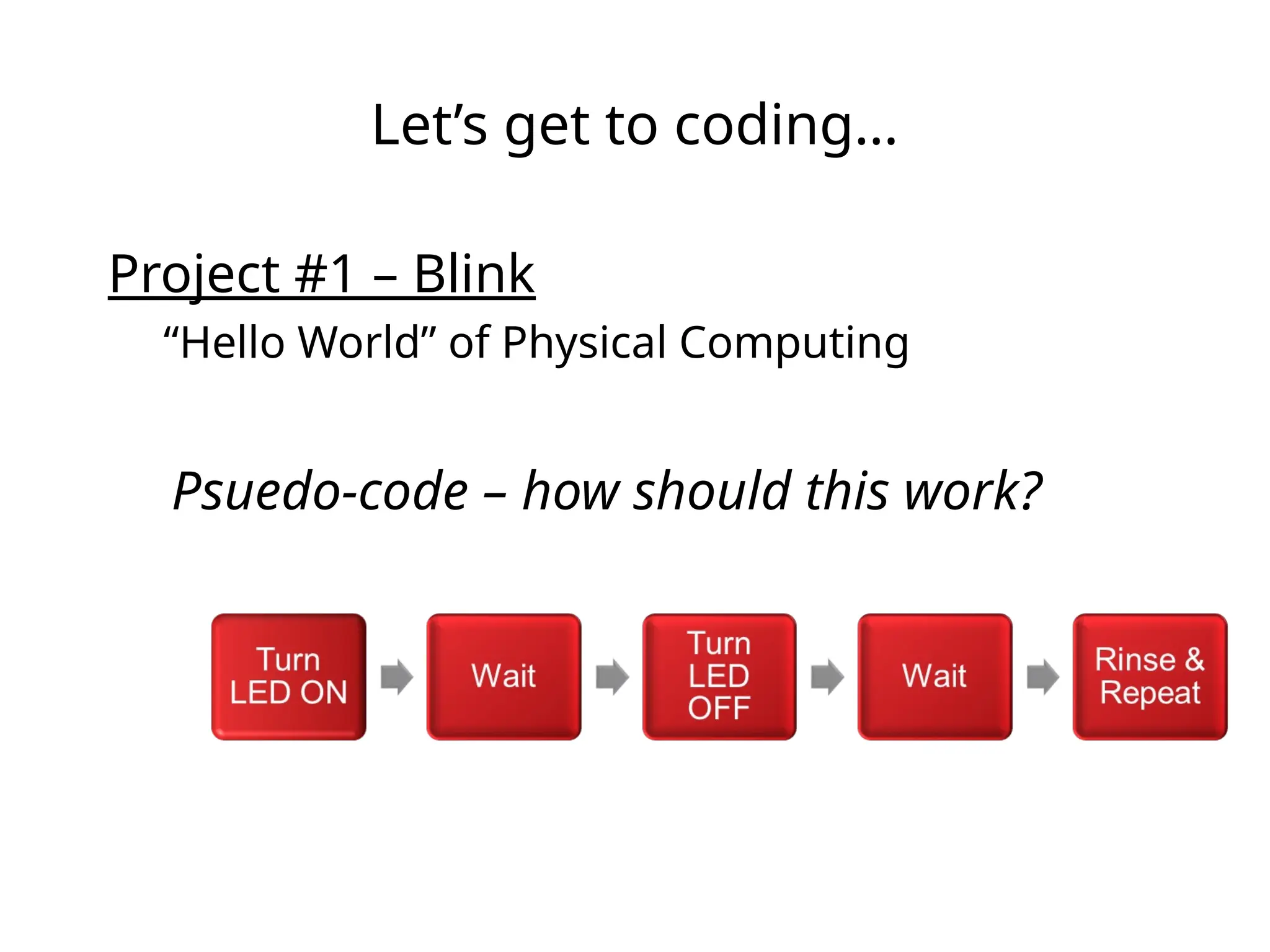
Let’s get tocoding…
Project #1 – Blink
“Hello World” of Physical Computing
Psuedo-code – how should this work?
45.
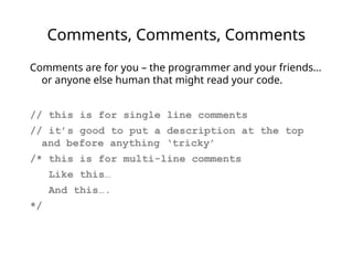
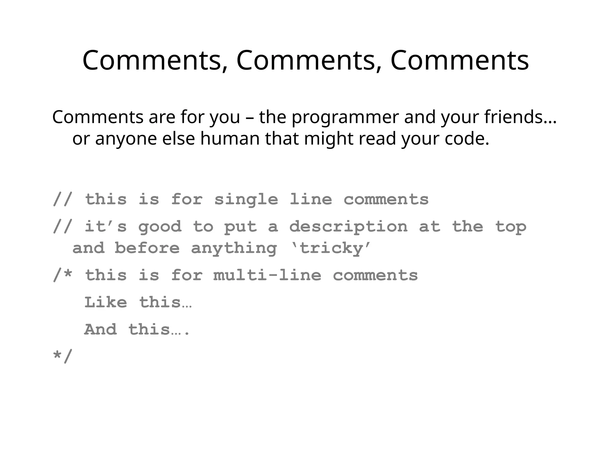
Comments, Comments, Comments
Commentsare for you – the programmer and your friends…
or anyone else human that might read your code.
// this is for single line comments
// it’s good to put a description at the top
and before anything ‘tricky’
/* this is for multi-line comments
Like this…
And this….
*/
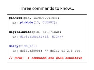
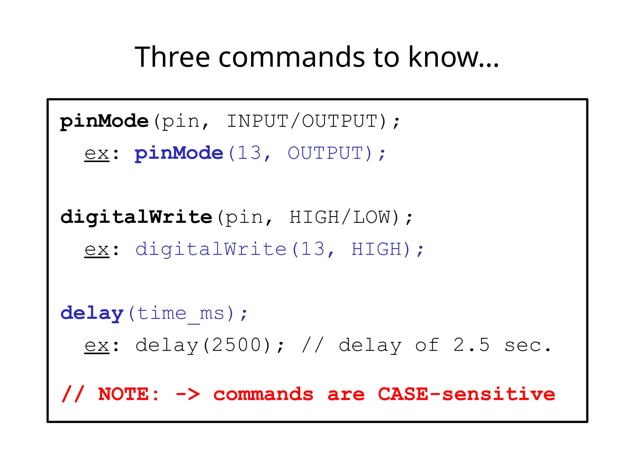
Three commands toknow…
pinMode(pin, INPUT/OUTPUT);
ex: pinMode(13, OUTPUT);
digitalWrite(pin, HIGH/LOW);
ex: digitalWrite(13, HIGH);
delay(time_ms);
ex: delay(2500); // delay of 2.5 sec.
// NOTE: -> commands are CASE-sensitive
48.
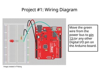
Project #1: WiringDiagram
Move the green
wire from the
power bus to pin
13 (or any other
Digital I/O pin on
the Arduino board.
Image created in Fritzing
49.
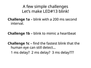
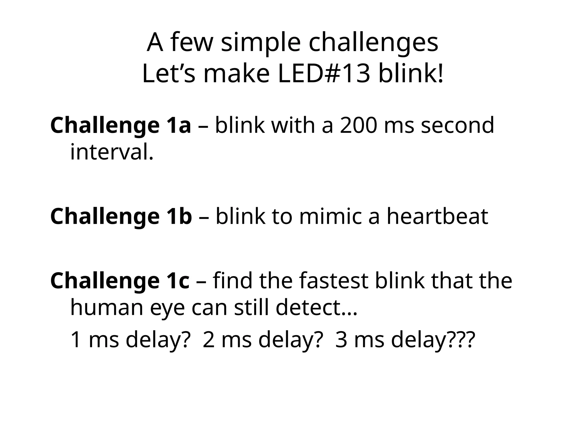
A few simplechallenges
Let’s make LED#13 blink!
Challenge 1a – blink with a 200 ms second
interval.
Challenge 1b – blink to mimic a heartbeat
Challenge 1c – find the fastest blink that the
human eye can still detect…
1 ms delay? 2 ms delay? 3 ms delay???
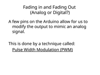
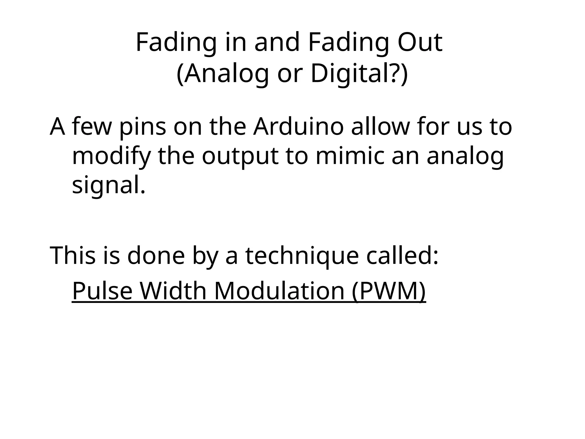
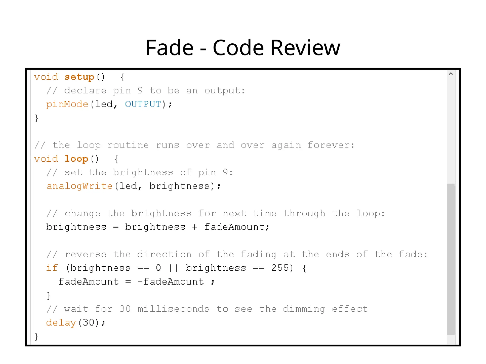
Fading in andFading Out
(Analog or Digital?)
A few pins on the Arduino allow for us to
modify the output to mimic an analog
signal.
This is done by a technique called:
Pulse Width Modulation (PWM)
54.
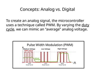
Concepts: Analog vs.Digital
To create an analog signal, the microcontroller
uses a technique called PWM. By varying the duty
cycle, we can mimic an “average” analog voltage.
Pulse Width Modulation (PWM)
55.
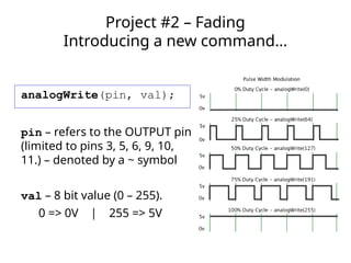
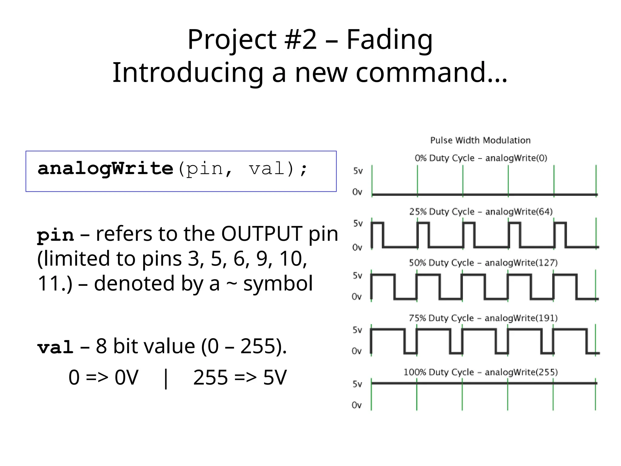
analogWrite(pin, val);
pin –refers to the OUTPUT pin
(limited to pins 3, 5, 6, 9, 10,
11.) – denoted by a ~ symbol
val – 8 bit value (0 – 255).
0 => 0V | 255 => 5V
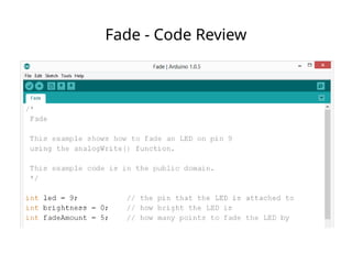
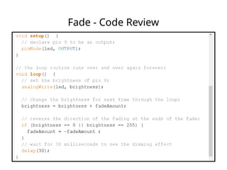
Project #2 – Fading
Introducing a new command…
56.
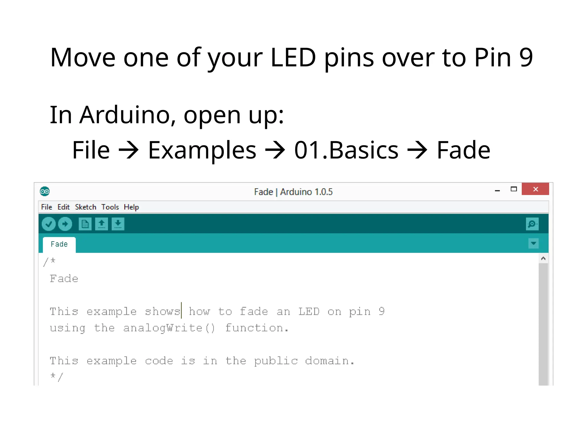
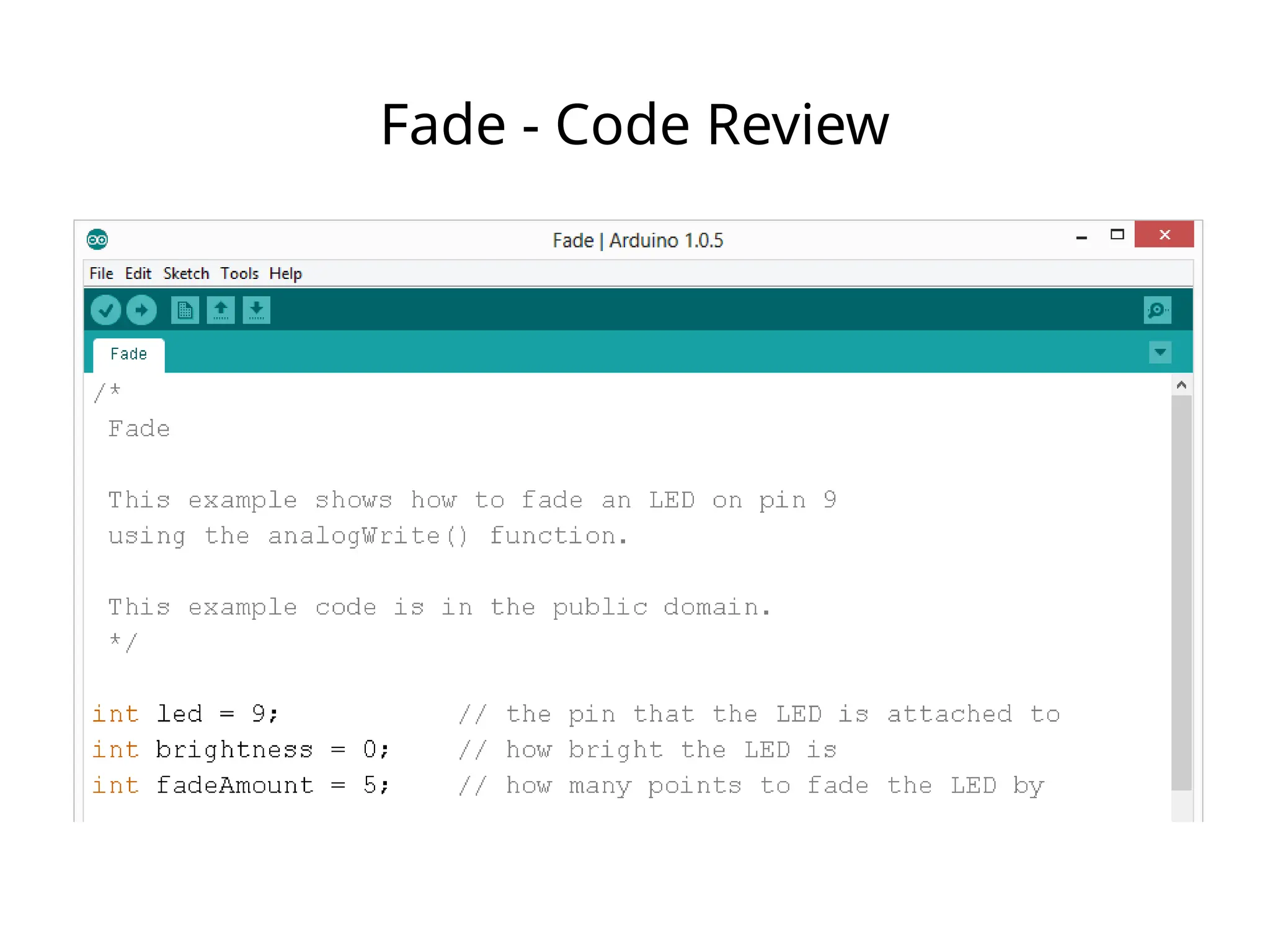
Move one ofyour LED pins over to Pin 9
In Arduino, open up:
File Examples 01.Basics Fade
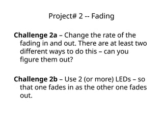
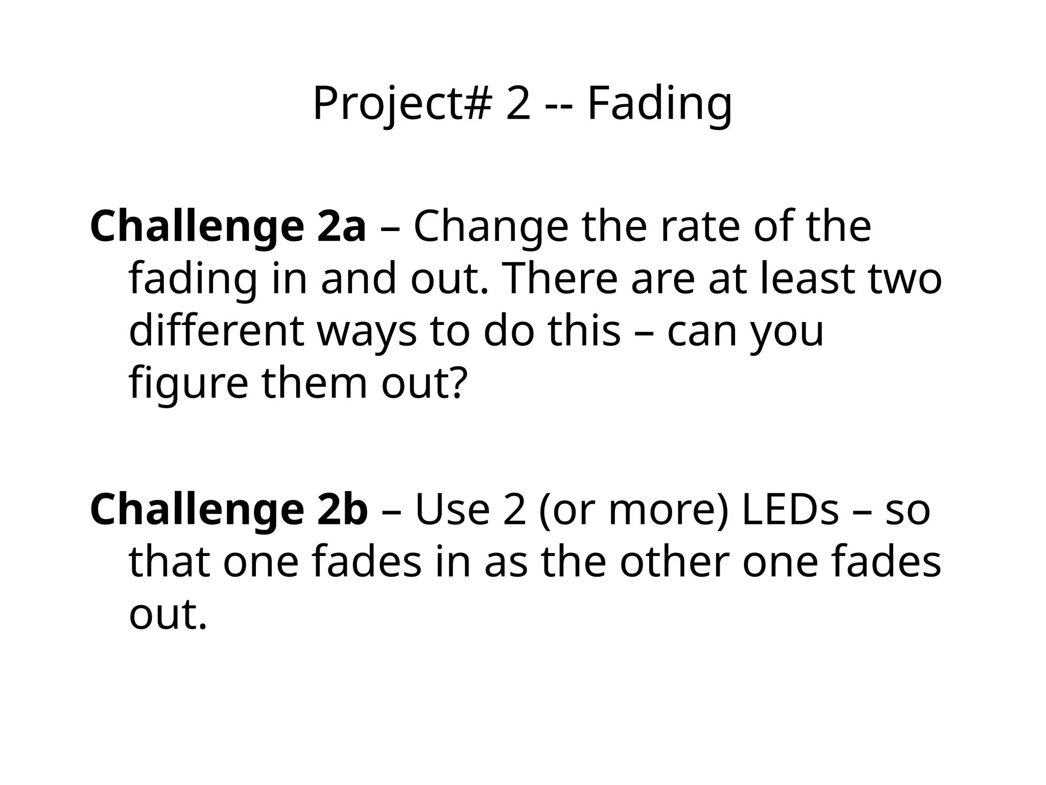
Project# 2 --Fading
Challenge 2a – Change the rate of the
fading in and out. There are at least two
different ways to do this – can you
figure them out?
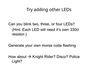
Challenge 2b – Use 2 (or more) LEDs – so
that one fades in as the other one fades
out.
60.
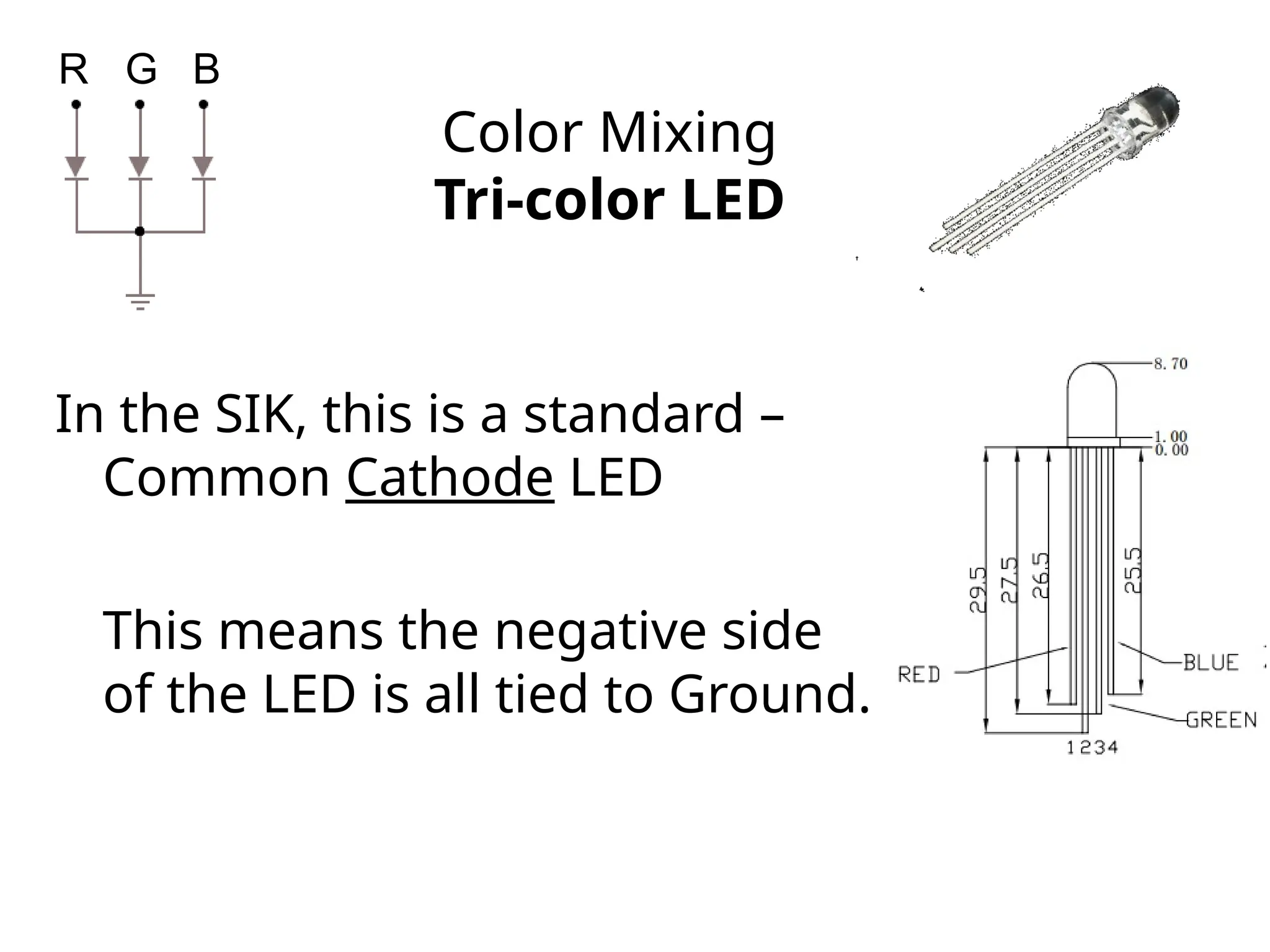
Color Mixing
Tri-color LED
Inthe SIK, this is a standard –
Common Cathode LED
This means the negative side
of the LED is all tied to Ground.
R G B
61.
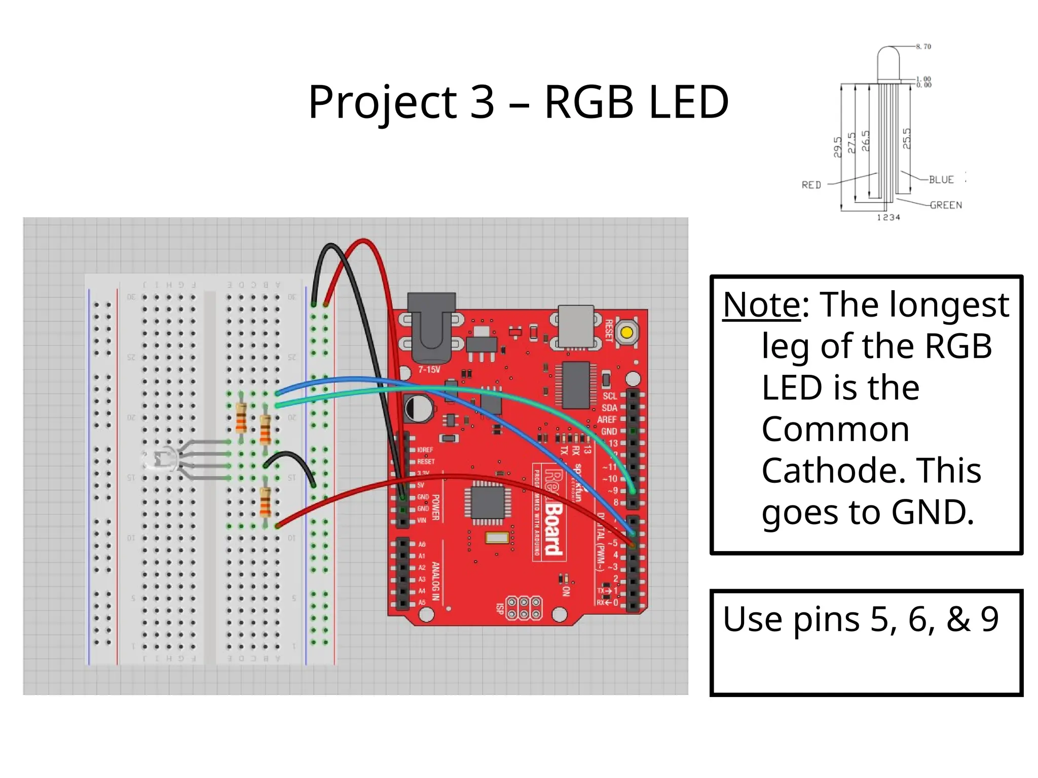
Project 3 –RGB LED
Note: The longest
leg of the RGB
LED is the
Common
Cathode. This
goes to GND.
Use pins 5, 6, & 9
62.
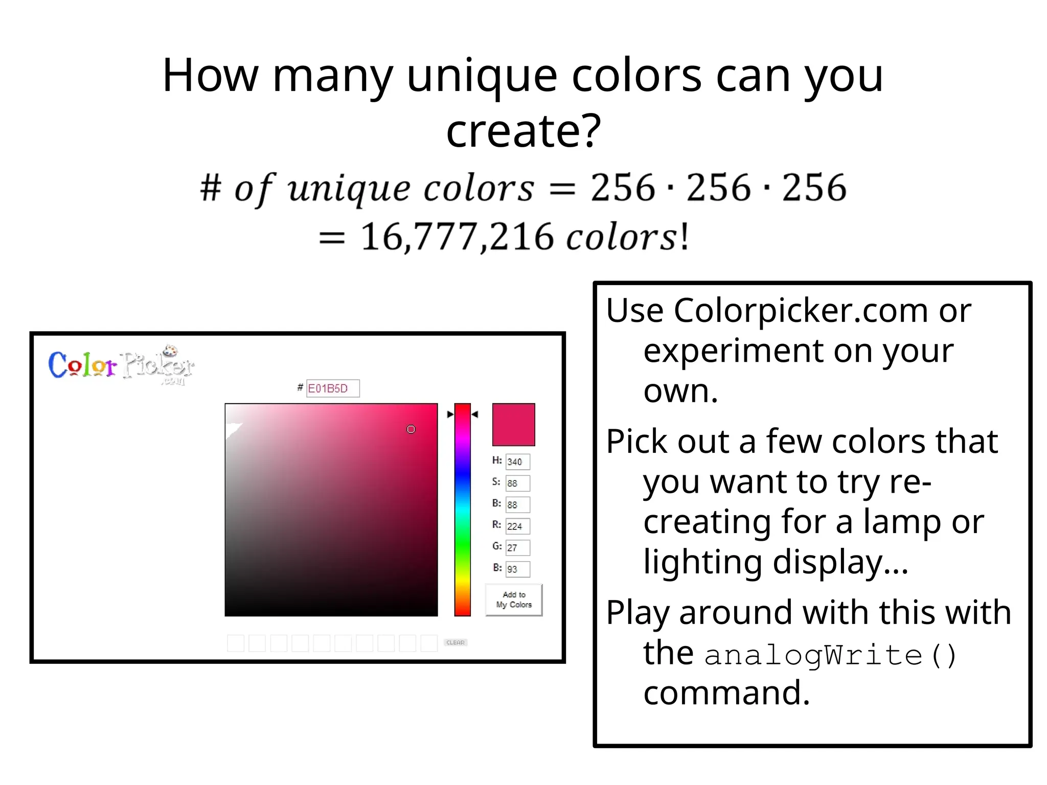
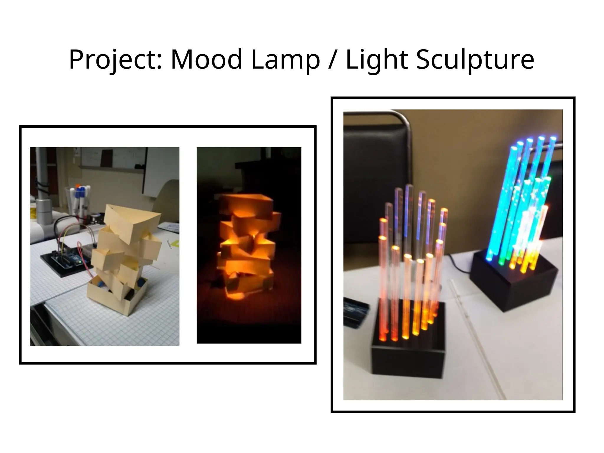
How many uniquecolors can you
create?
Use Colorpicker.com or
experiment on your
own.
Pick out a few colors that
you want to try re-
creating for a lamp or
lighting display...
Play around with this with
the analogWrite()
command.
63.
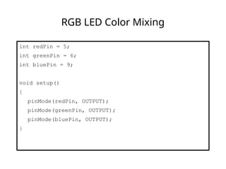
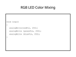
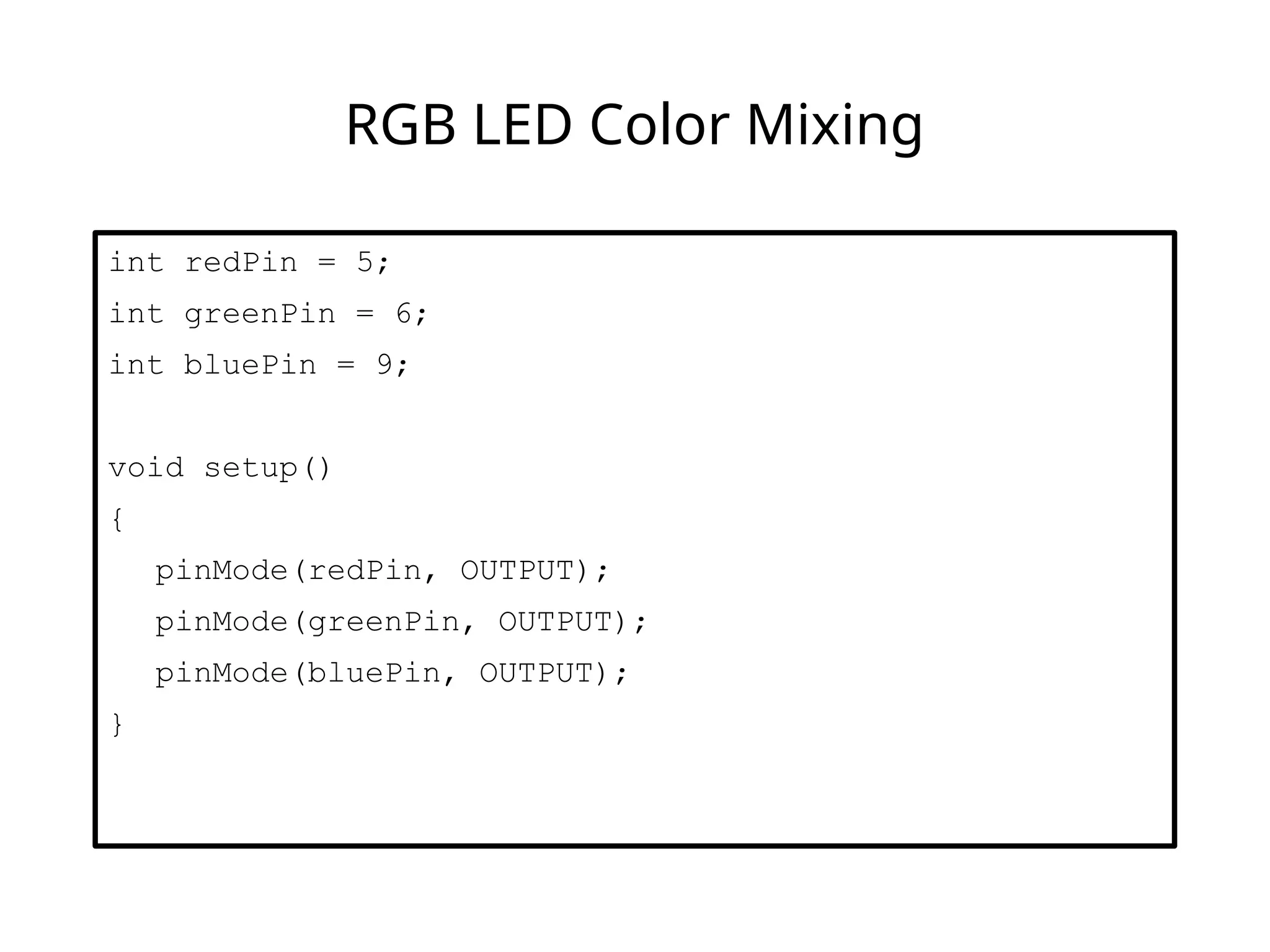
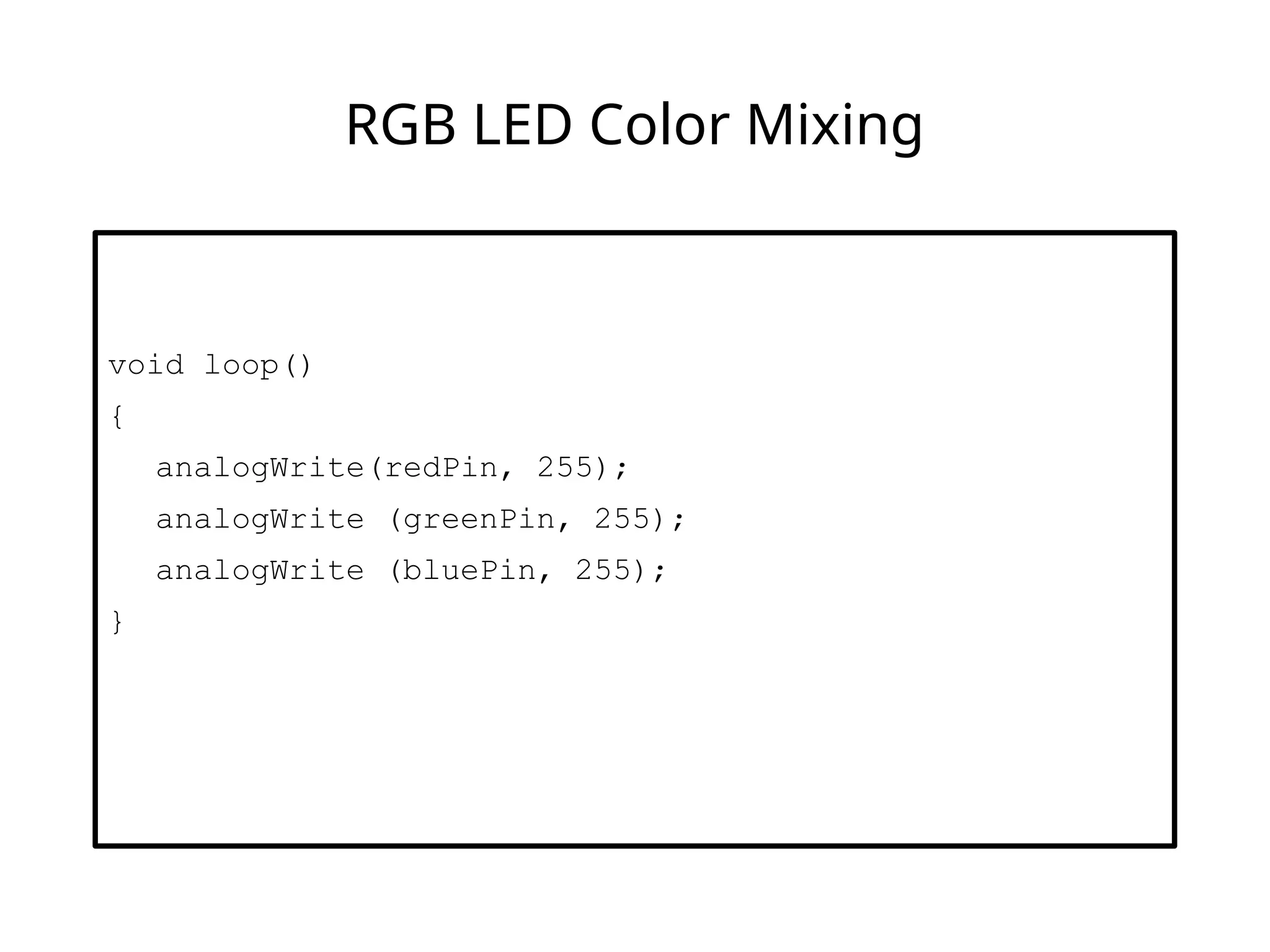
RGB LED ColorMixing
int redPin = 5;
int greenPin = 6;
int bluePin = 9;
void setup()
{
pinMode(redPin, OUTPUT);
pinMode(greenPin, OUTPUT);
pinMode(bluePin, OUTPUT);
}
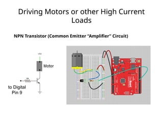
Driving Motors orother High Current
Loads
NPN Transistor (Common Emitter “Amplifier” Circuit)
to Digital
Pin 9
69.
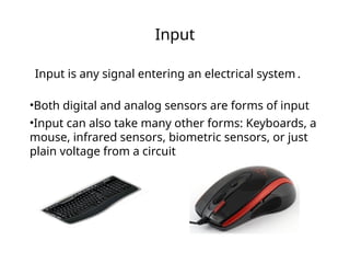
Input
Input is anysignal entering an electrical system .
•Both digital and analog sensors are forms of input
•Input can also take many other forms: Keyboards, a
mouse, infrared sensors, biometric sensors, or just
plain voltage from a circuit
70.
Project #4 –Digital Input
In Arduino, open up:
File Examples 02.Digital Button
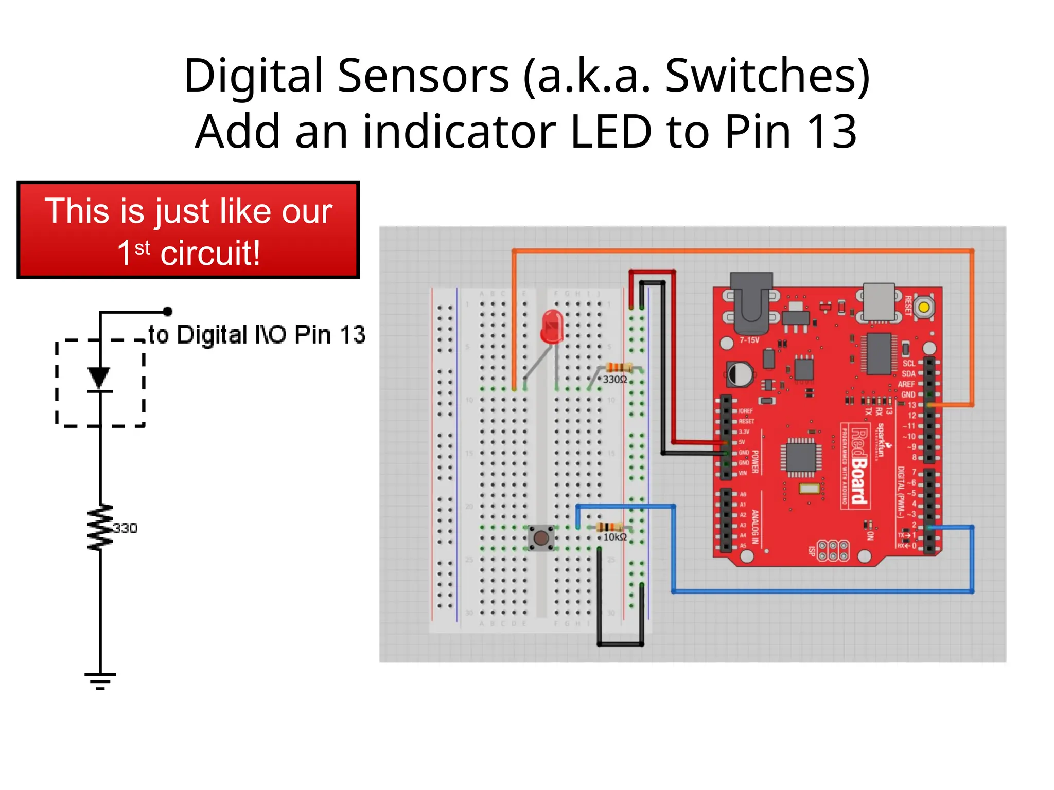
Digital Sensors (a.k.a.Switches)
Add an indicator LED to Pin 13
This is just like our
1st
circuit!
73.
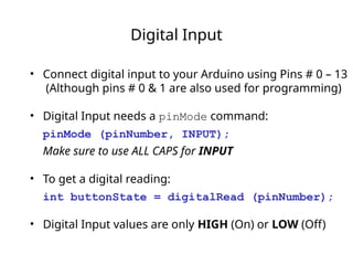
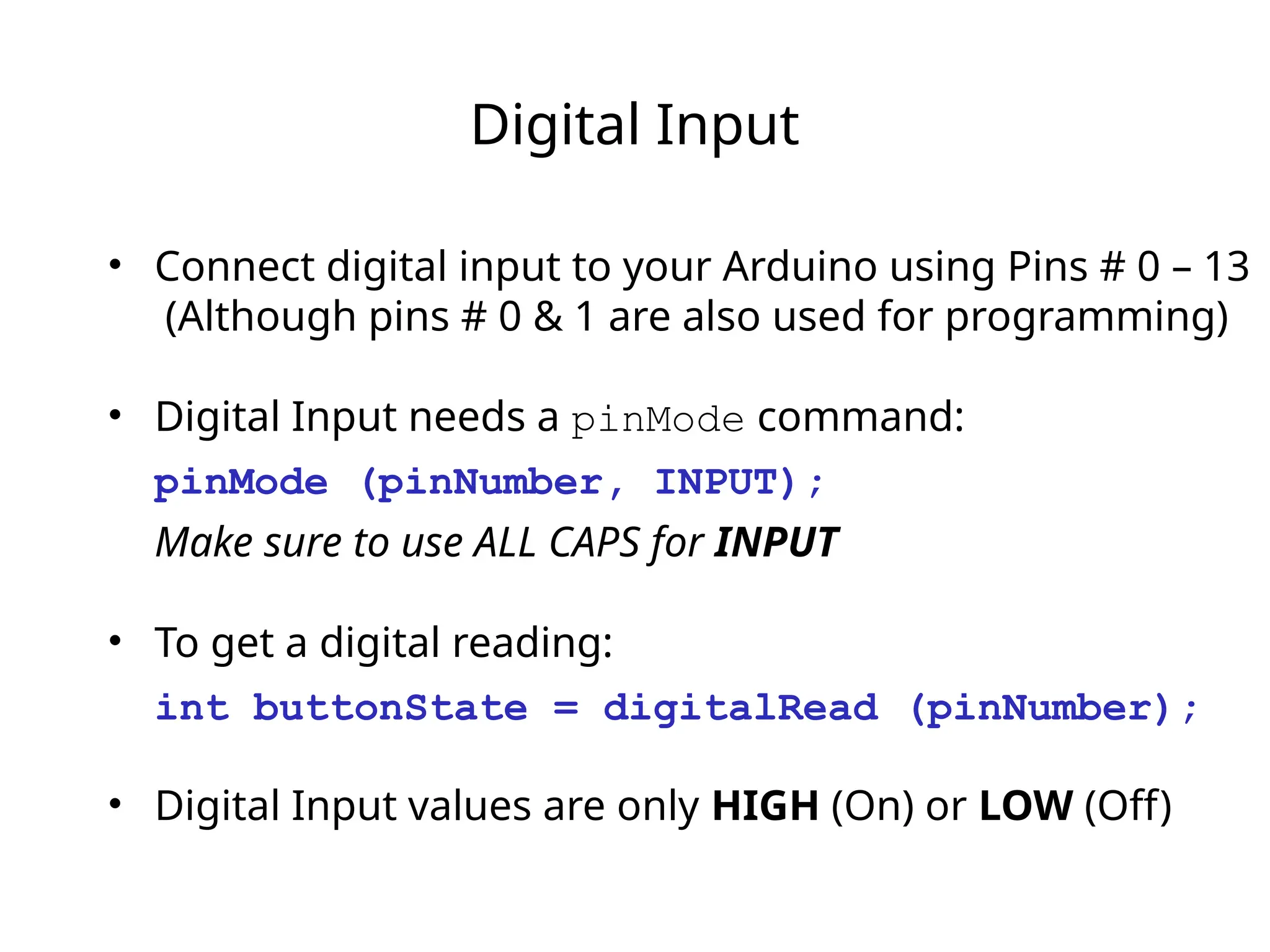
Digital Input
• Connectdigital input to your Arduino using Pins # 0 – 13
(Although pins # 0 & 1 are also used for programming)
• Digital Input needs a pinMode command:
pinMode (pinNumber, INPUT);
Make sure to use ALL CAPS for INPUT
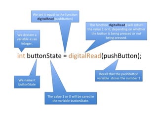
• To get a digital reading:
int buttonState = digitalRead (pinNumber);
• Digital Input values are only HIGH (On) or LOW (Off)
74.
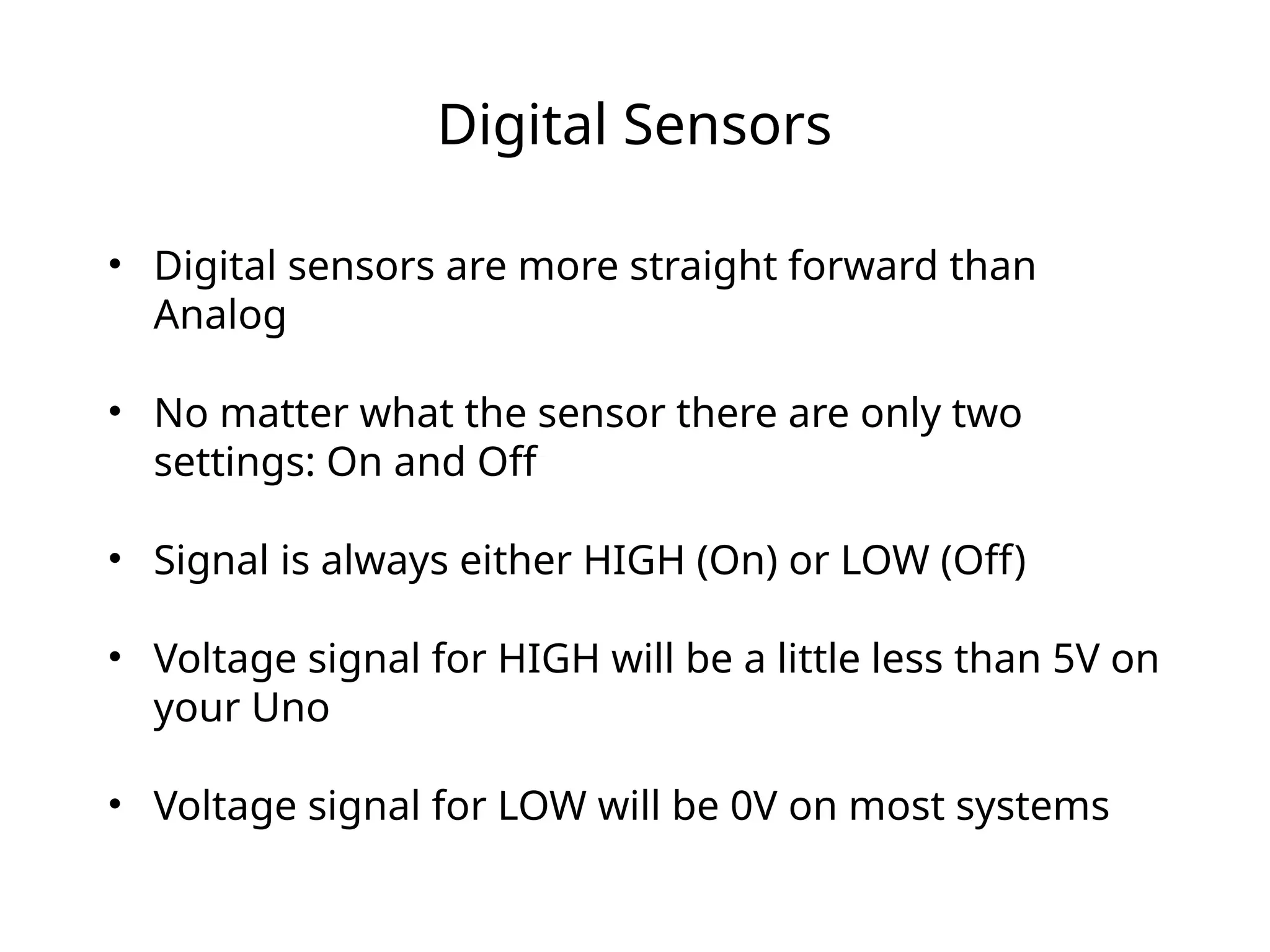
Digital Sensors
• Digitalsensors are more straight forward than
Analog
• No matter what the sensor there are only two
settings: On and Off
• Signal is always either HIGH (On) or LOW (Off)
• Voltage signal for HIGH will be a little less than 5V on
your Uno
• Voltage signal for LOW will be 0V on most systems
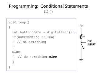
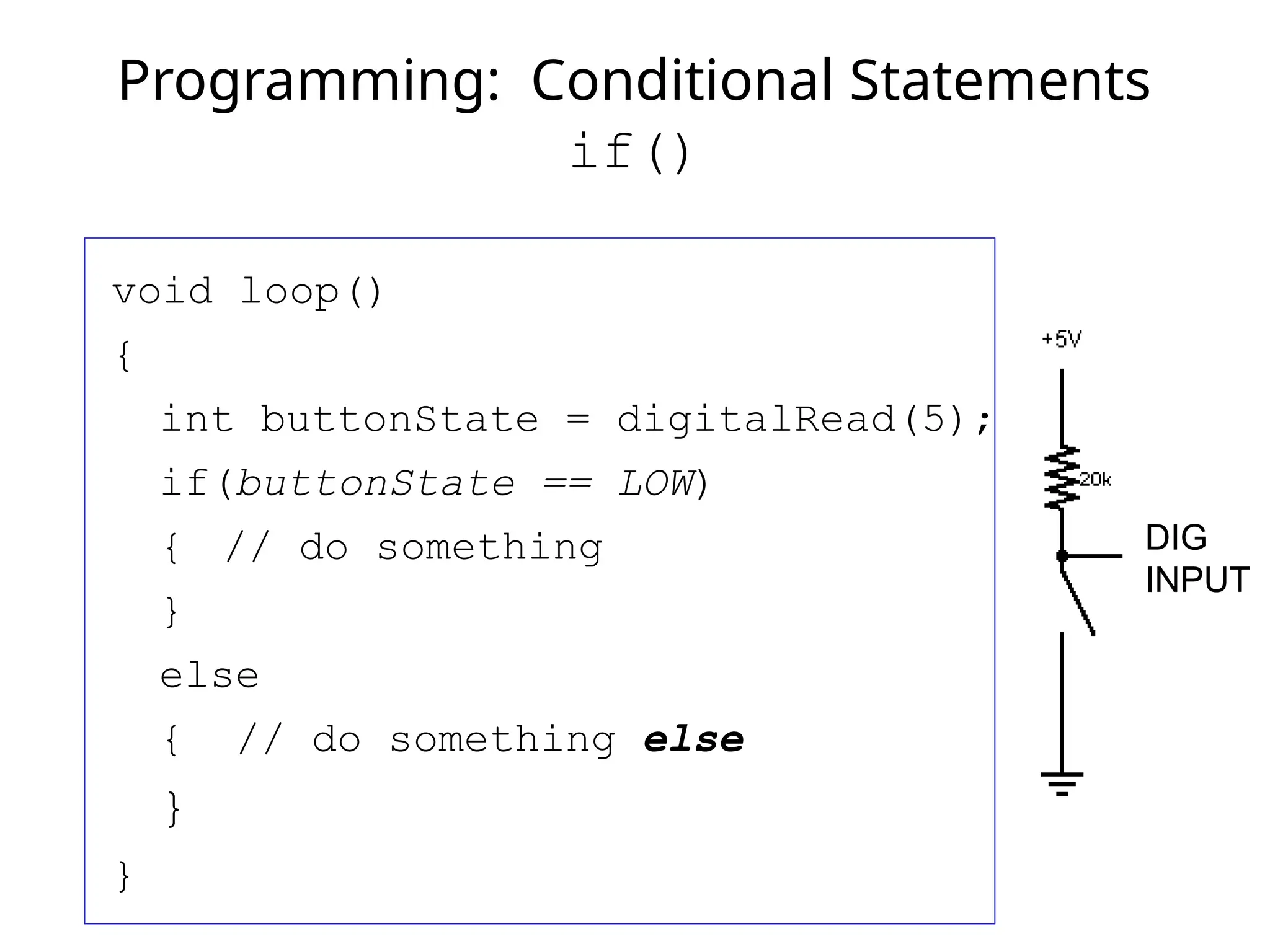
void loop()
{
int buttonState= digitalRead(5);
if(buttonState == LOW)
{ // do something
}
else
{ // do something else
}
}
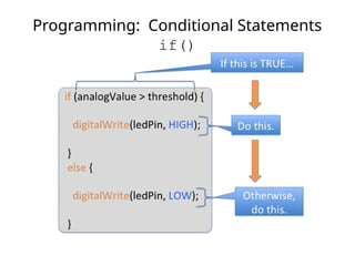
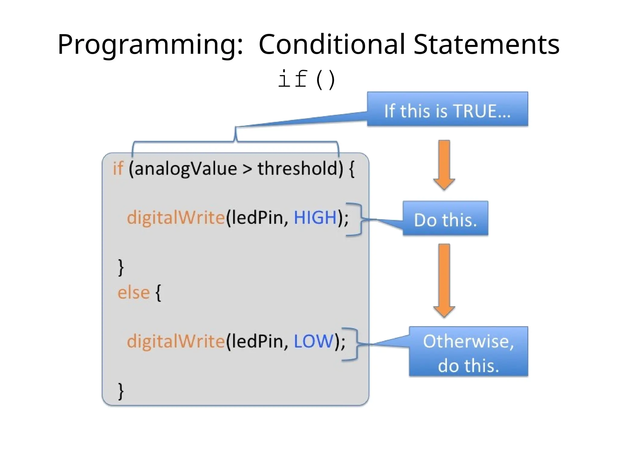
Programming: Conditional Statements
if()
DIG
INPUT
78.
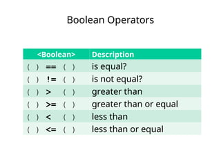
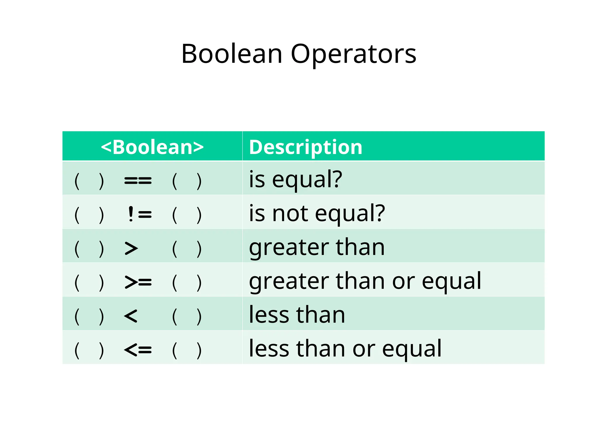
Boolean Operators
<Boolean> Description
() == ( ) is equal?
( ) != ( ) is not equal?
( ) > ( ) greater than
( ) >= ( ) greater than or equal
( ) < ( ) less than
( ) <= ( ) less than or equal
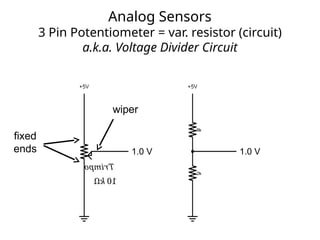
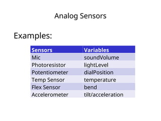
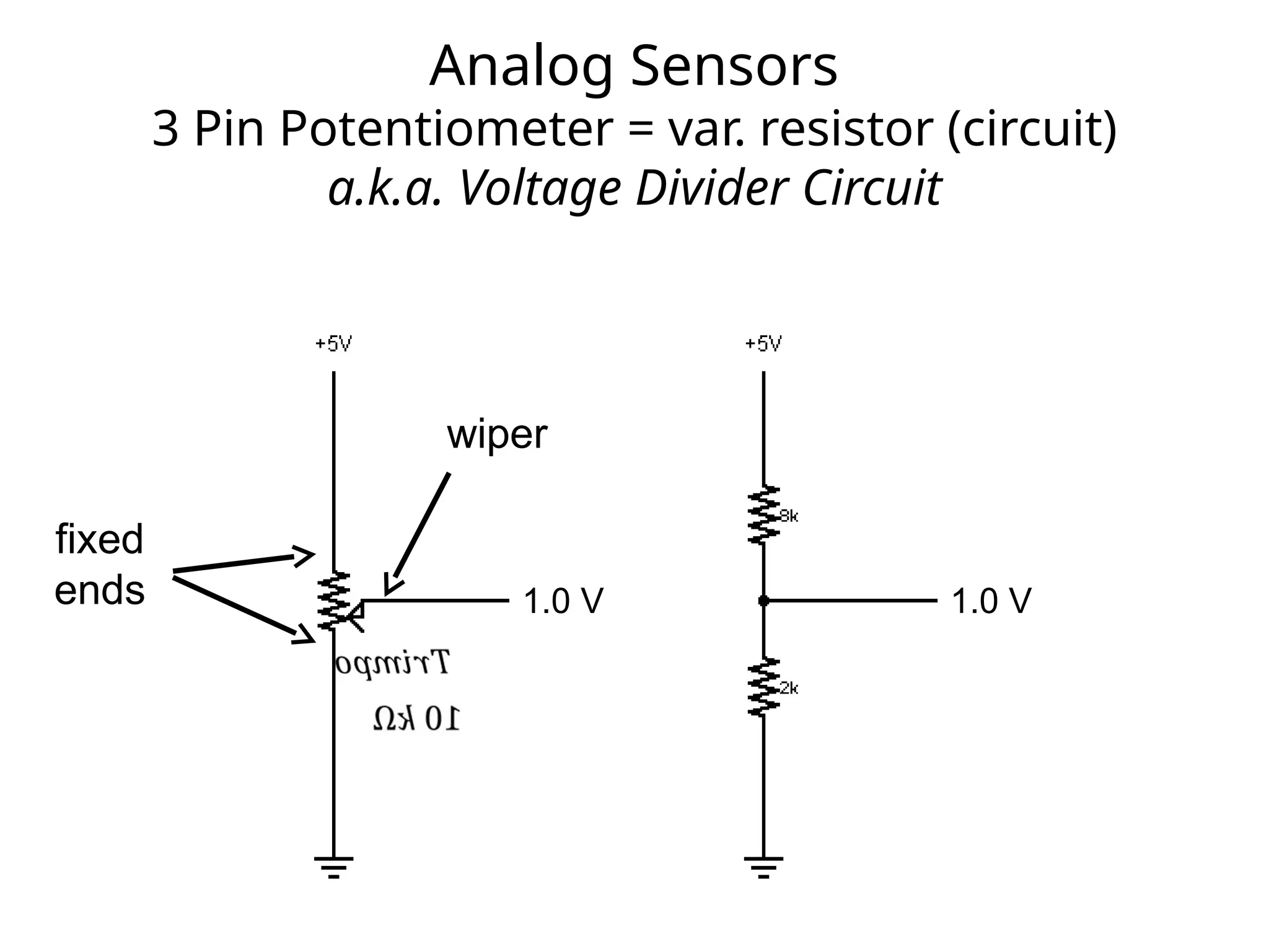
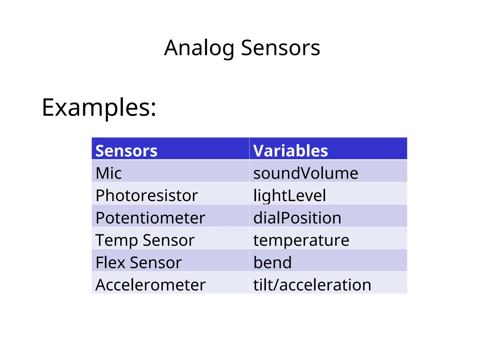
Analog Sensors
3 PinPotentiometer = var. resistor (circuit)
a.k.a. Voltage Divider Circuit
1.0 V 1.0 V
wiper
fixed
ends
81.
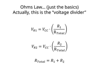
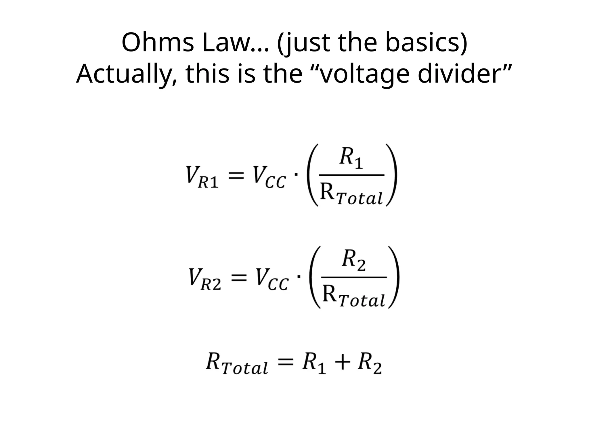
Ohms Law… (justthe basics)
Actually, this is the “voltage divider”
82.
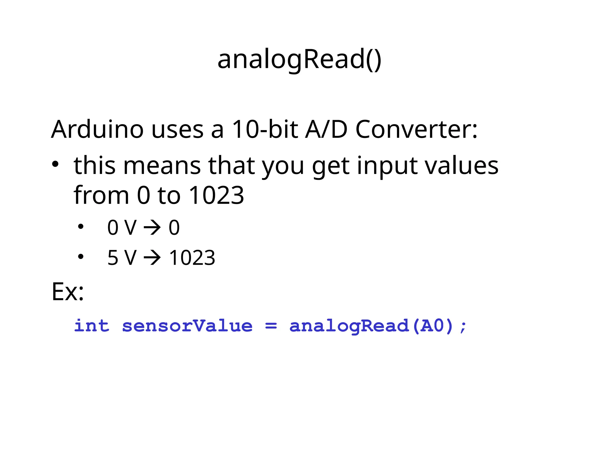
analogRead()
Arduino uses a10-bit A/D Converter:
• this means that you get input values
from 0 to 1023
• 0 V 0
• 5 V 1023
Ex:
int sensorValue = analogRead(A0);
83.
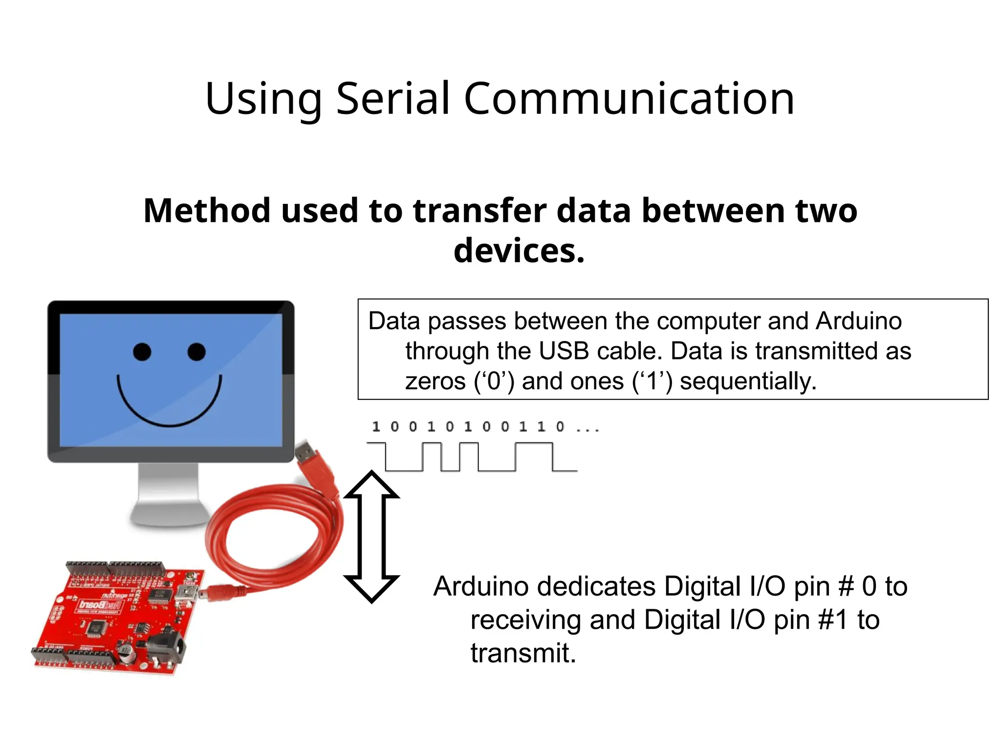
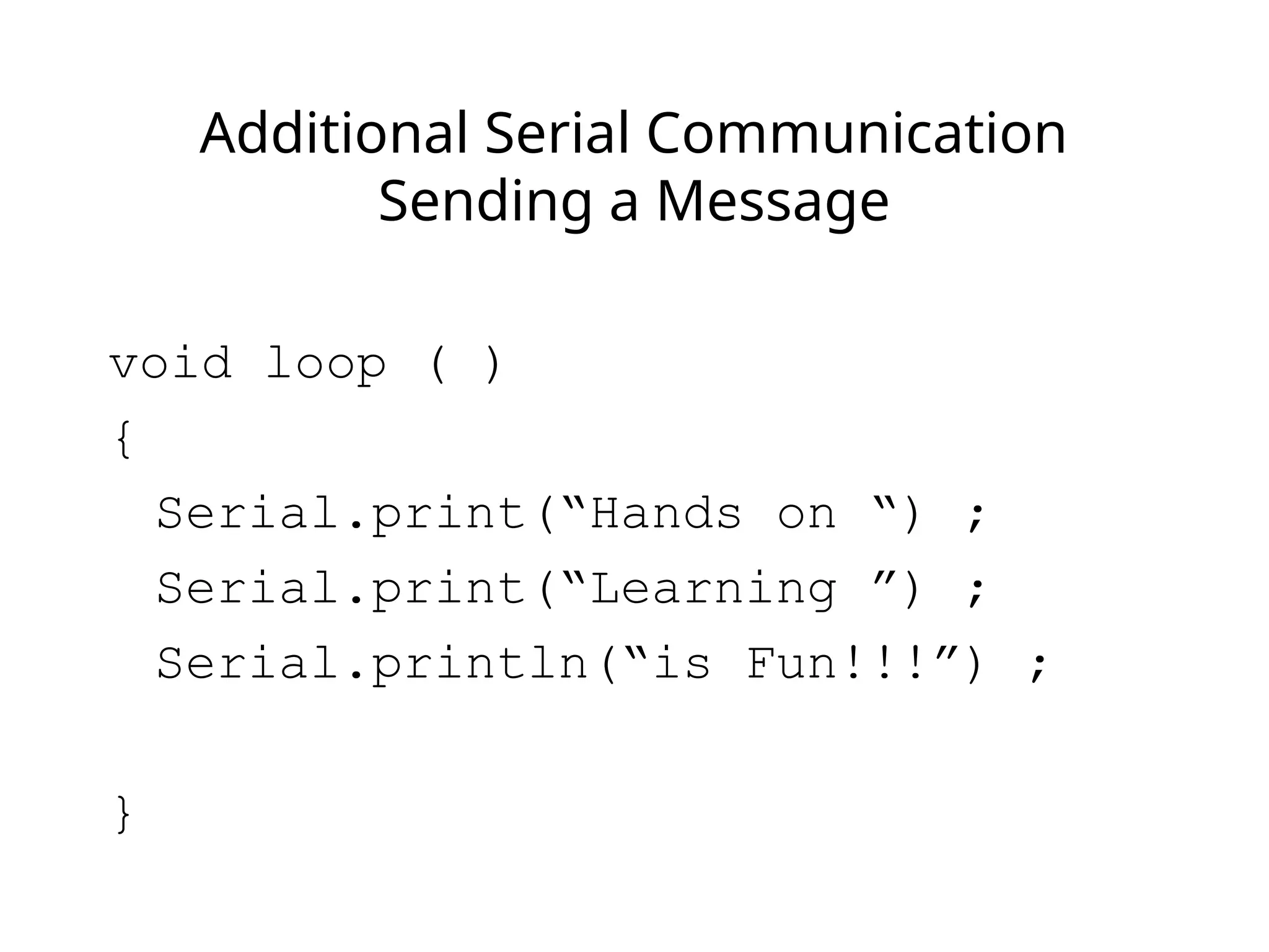
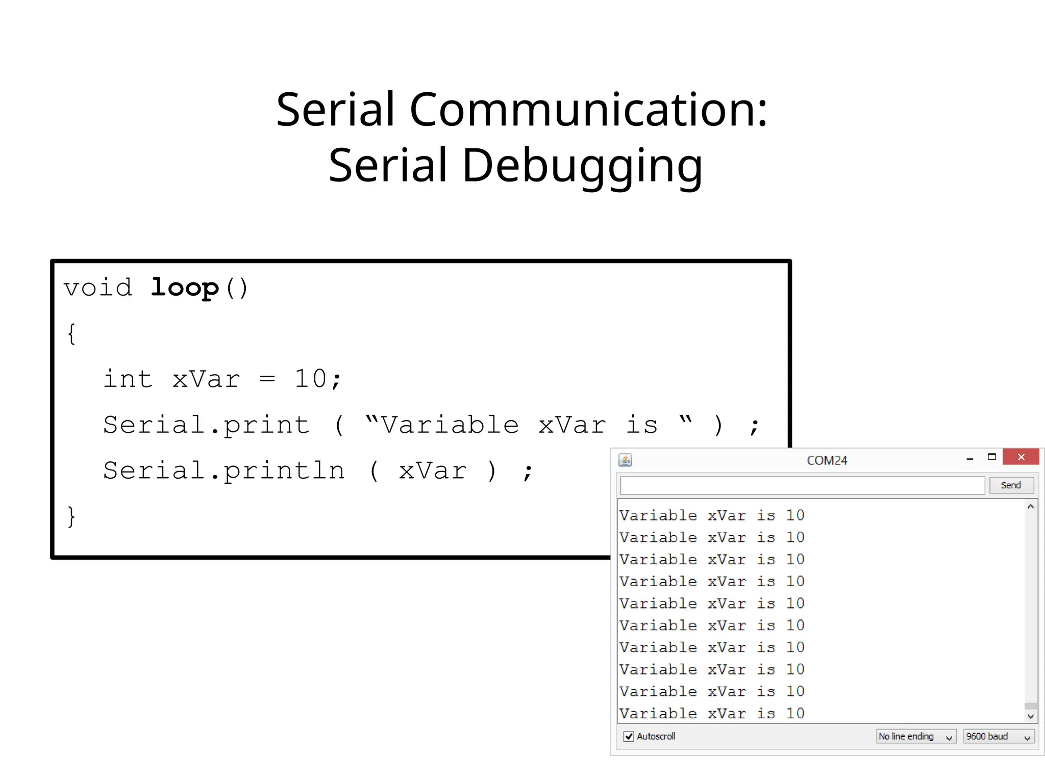
Using Serial Communication
Methodused to transfer data between two
devices.
Arduino dedicates Digital I/O pin # 0 to
receiving and Digital I/O pin #1 to
transmit.
Data passes between the computer and Arduino
through the USB cable. Data is transmitted as
zeros (‘0’) and ones (‘1’) sequentially.
84.
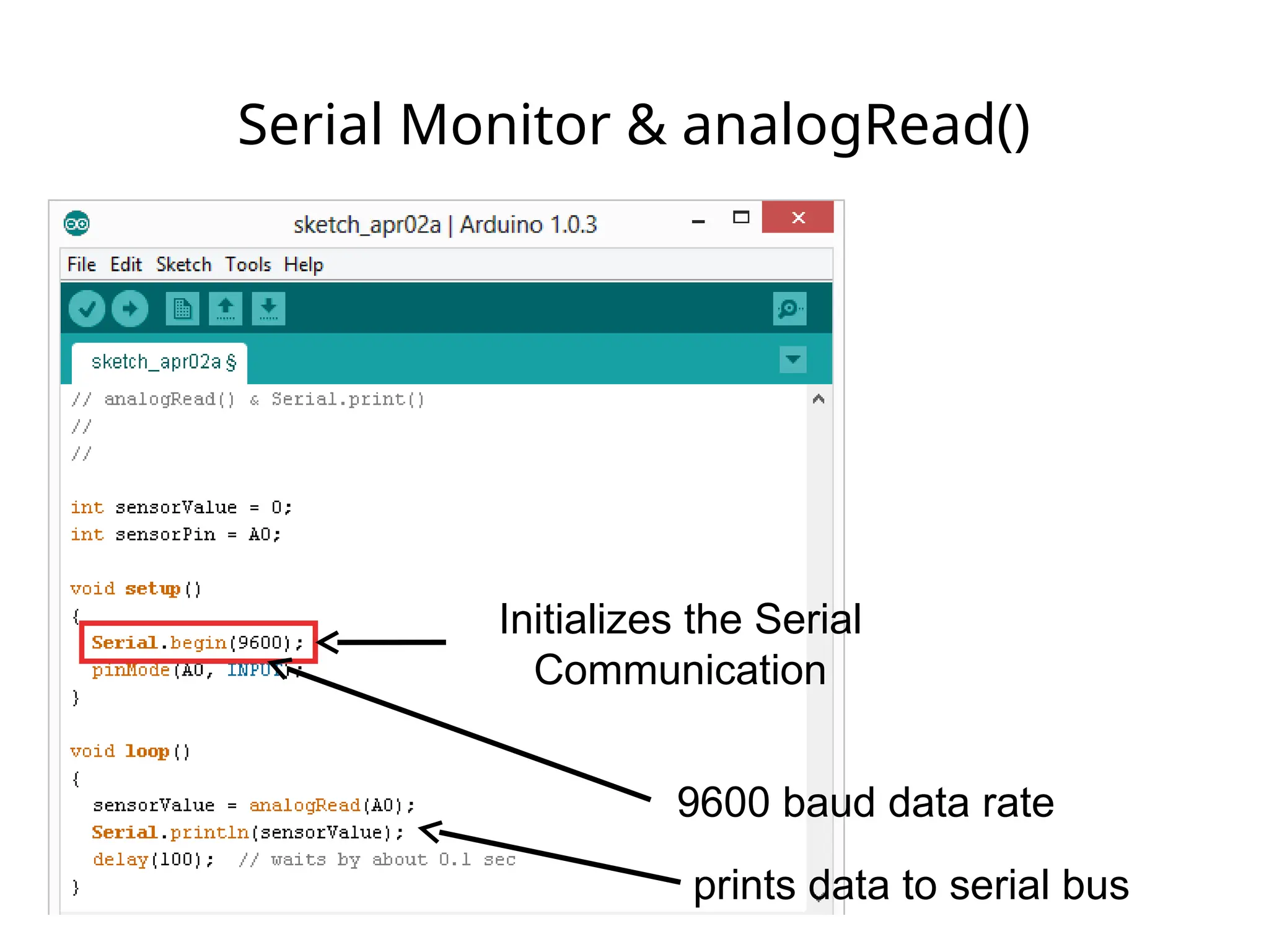
Serial Monitor &analogRead()
Initializes the Serial
Communication
9600 baud data rate
prints data to serial bus
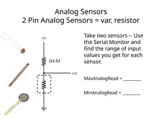
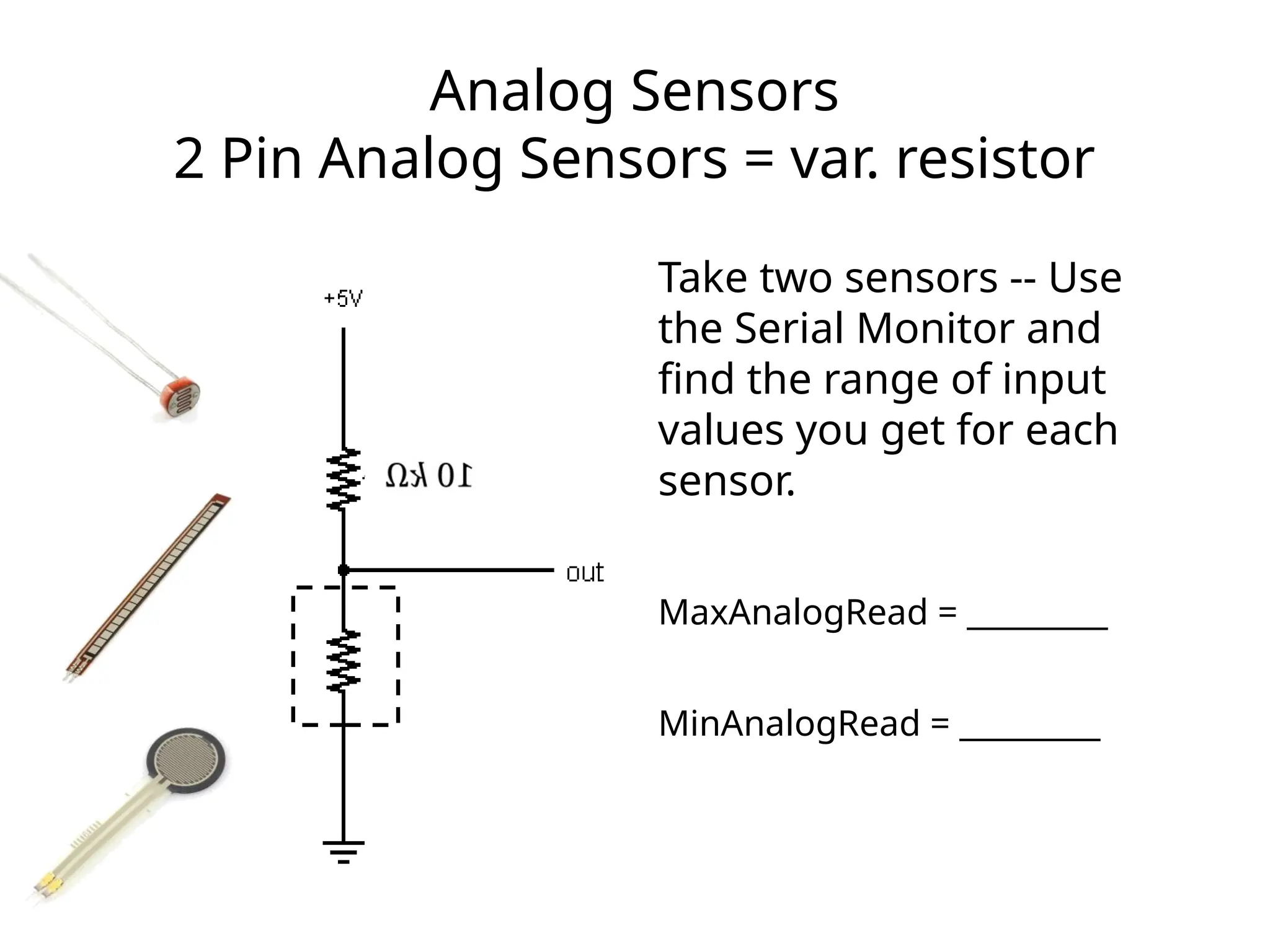
Analog Sensors
2 PinAnalog Sensors = var. resistor
Take two sensors -- Use
the Serial Monitor and
find the range of input
values you get for each
sensor.
MaxAnalogRead = _________
MinAnalogRead = _________
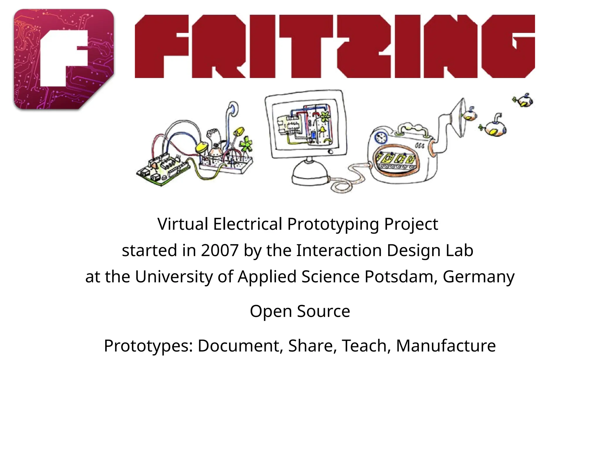
Virtual Electrical PrototypingProject
started in 2007 by the Interaction Design Lab
at the University of Applied Science Potsdam, Germany
Open Source
Prototypes: Document, Share, Teach, Manufacture
93.
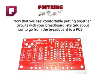
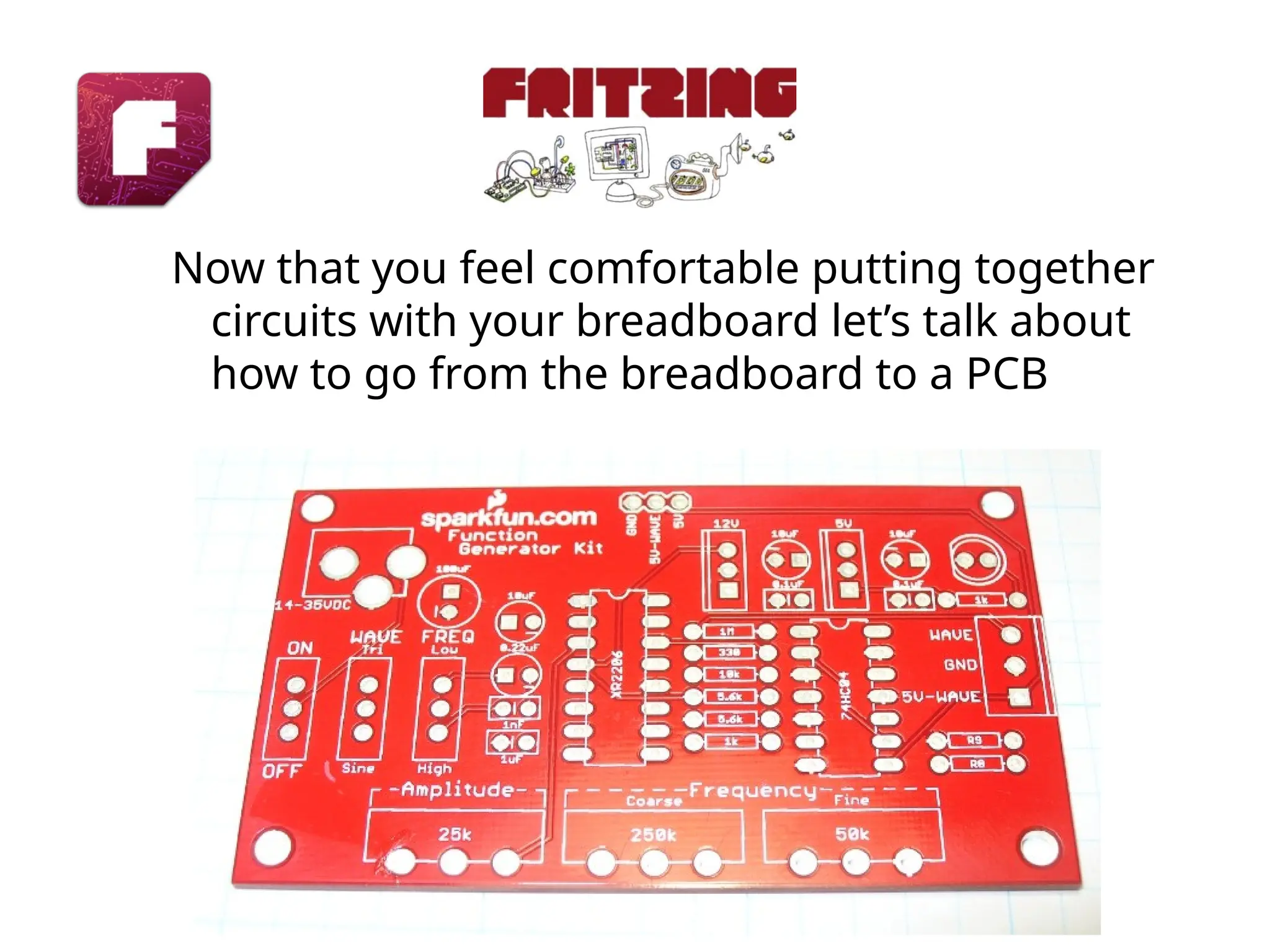
Now that youfeel comfortable putting together
circuits with your breadboard let’s talk about
how to go from the breadboard to a PCB
#40 Be sure to point out the what all of the buttons do.
#41 All connections to computers- mice, printers etc use a serial port. Gotta pick the right one.
#42 All connections to computers- mice, printers etc use a serial port. Gotta pick the right one.
#47 Review the two main parts of the sketch – void setup() and void loop()
Provide rationale for good commenting.
Emphasize the need for good / clean coding practices like indenting.
#48 Three commands to rule the world… or at least do 80% of cool Arduino projects.
#66 Here are a few examples of project ideas that you can extend this to in the class.