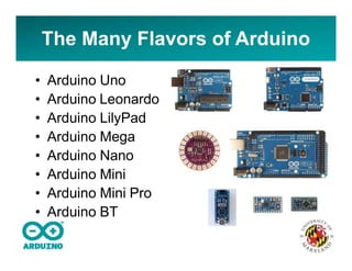
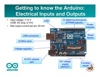
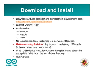
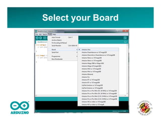
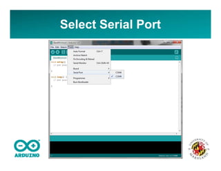
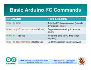
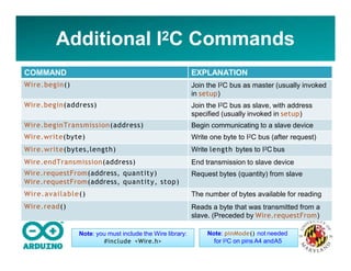
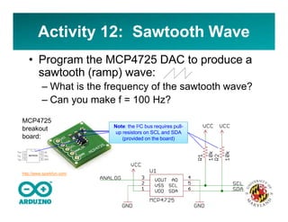
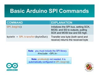
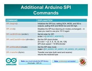
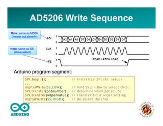
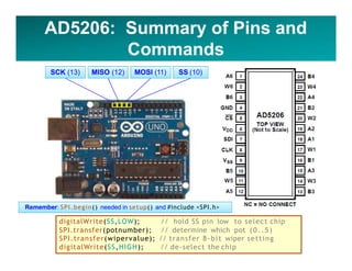
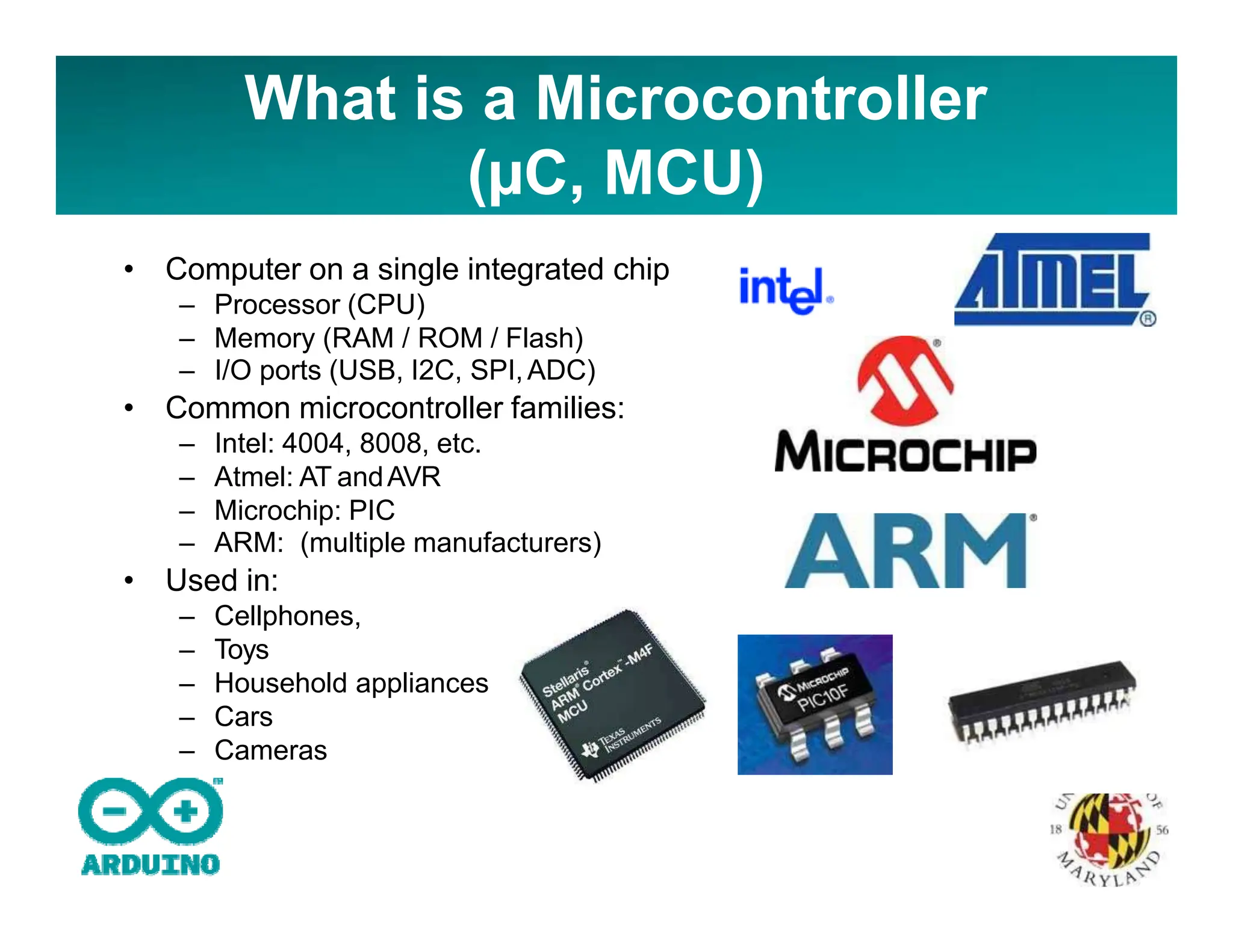
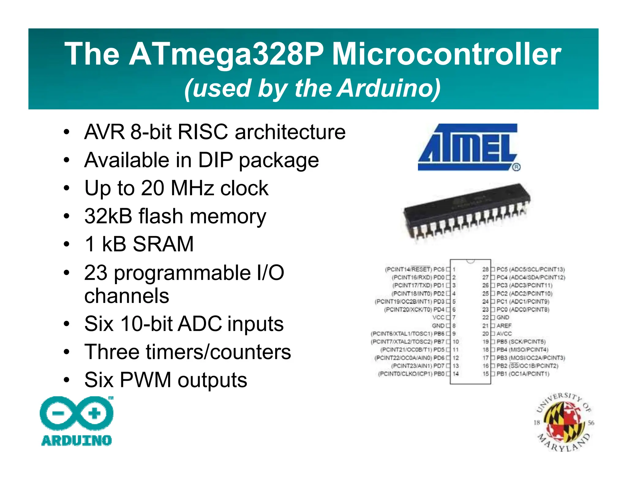
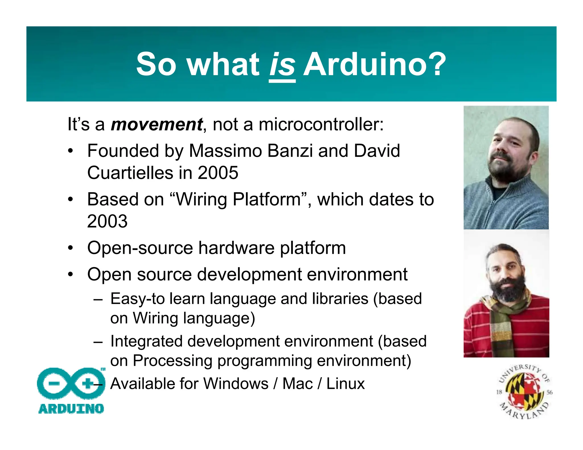
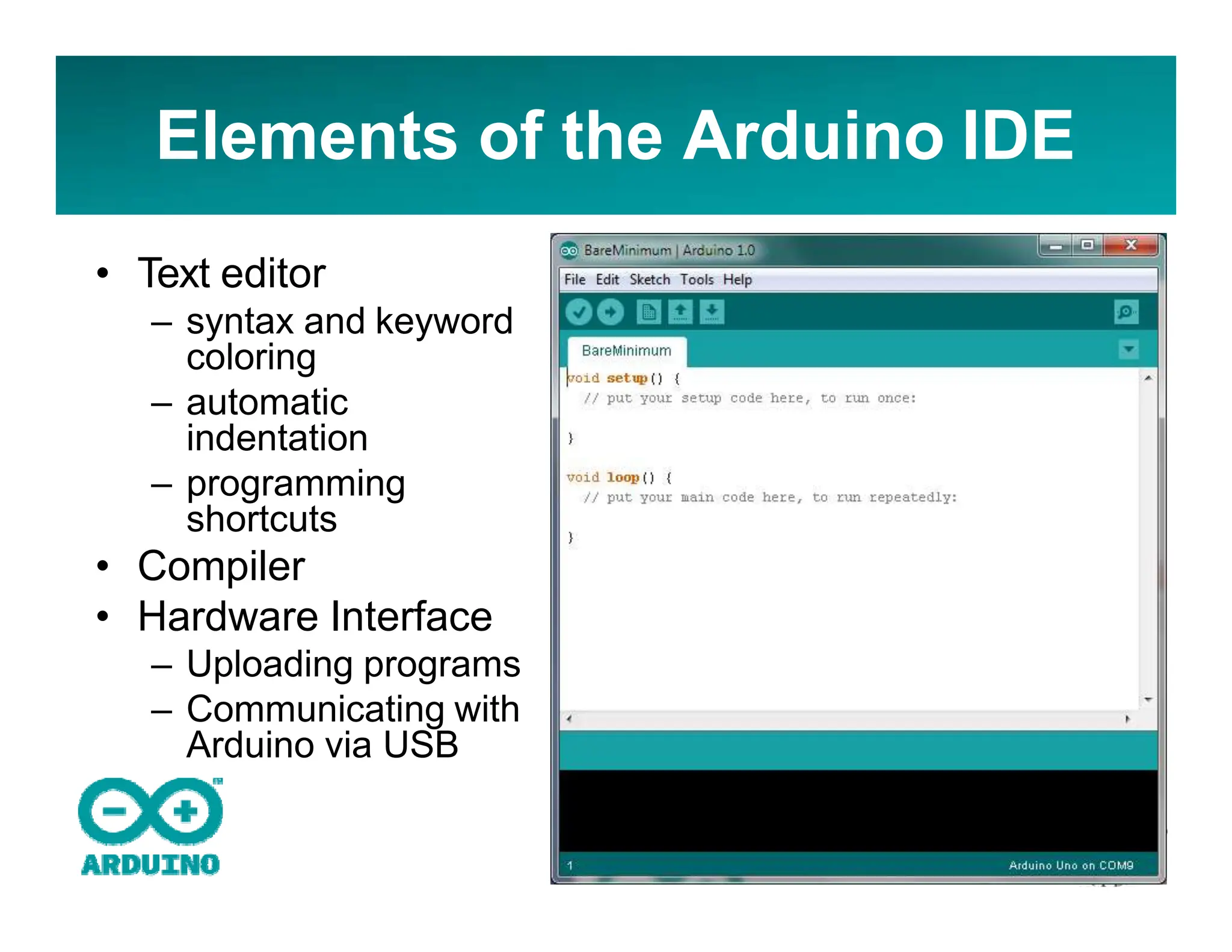
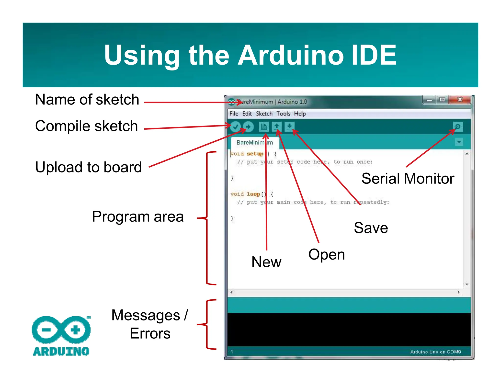
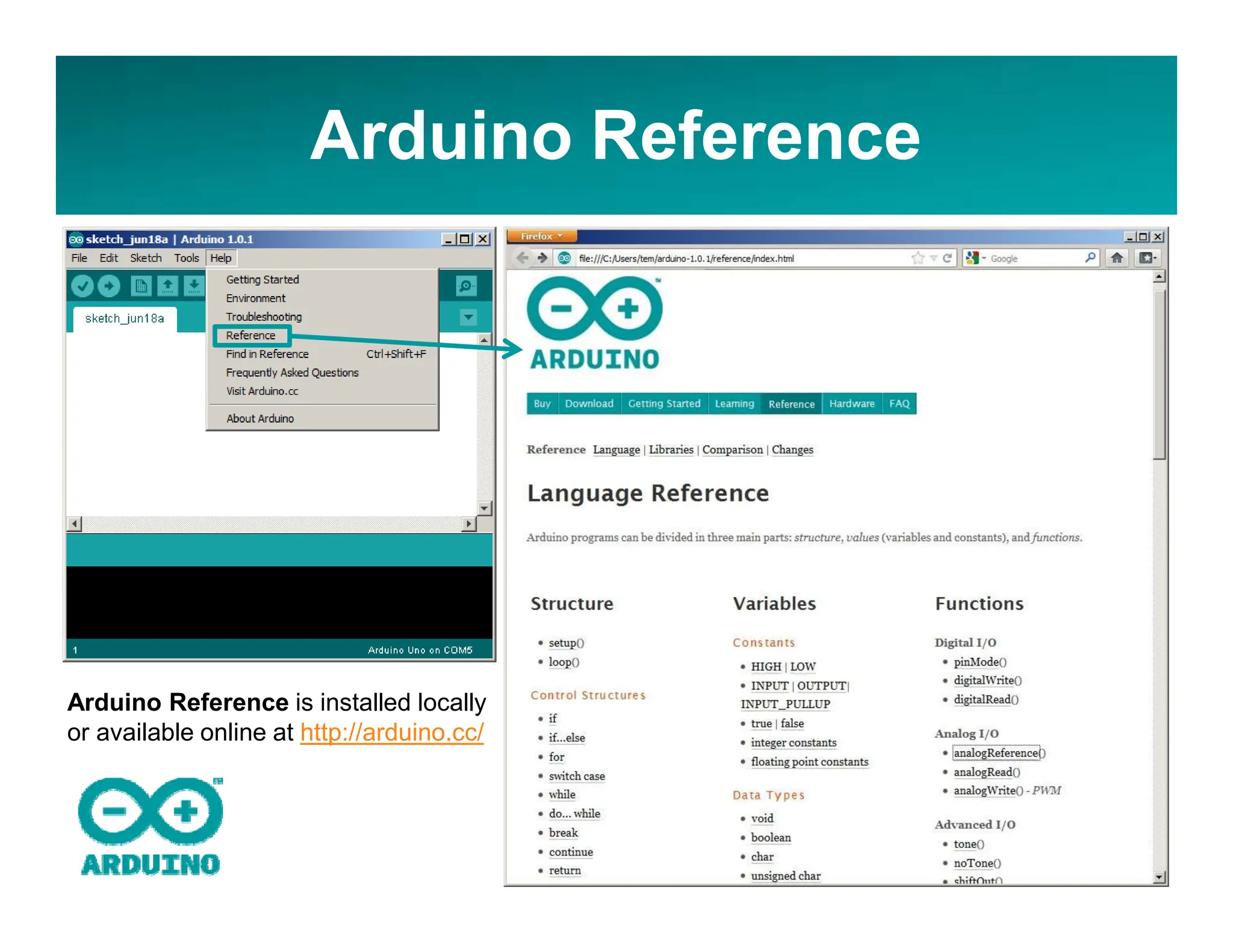
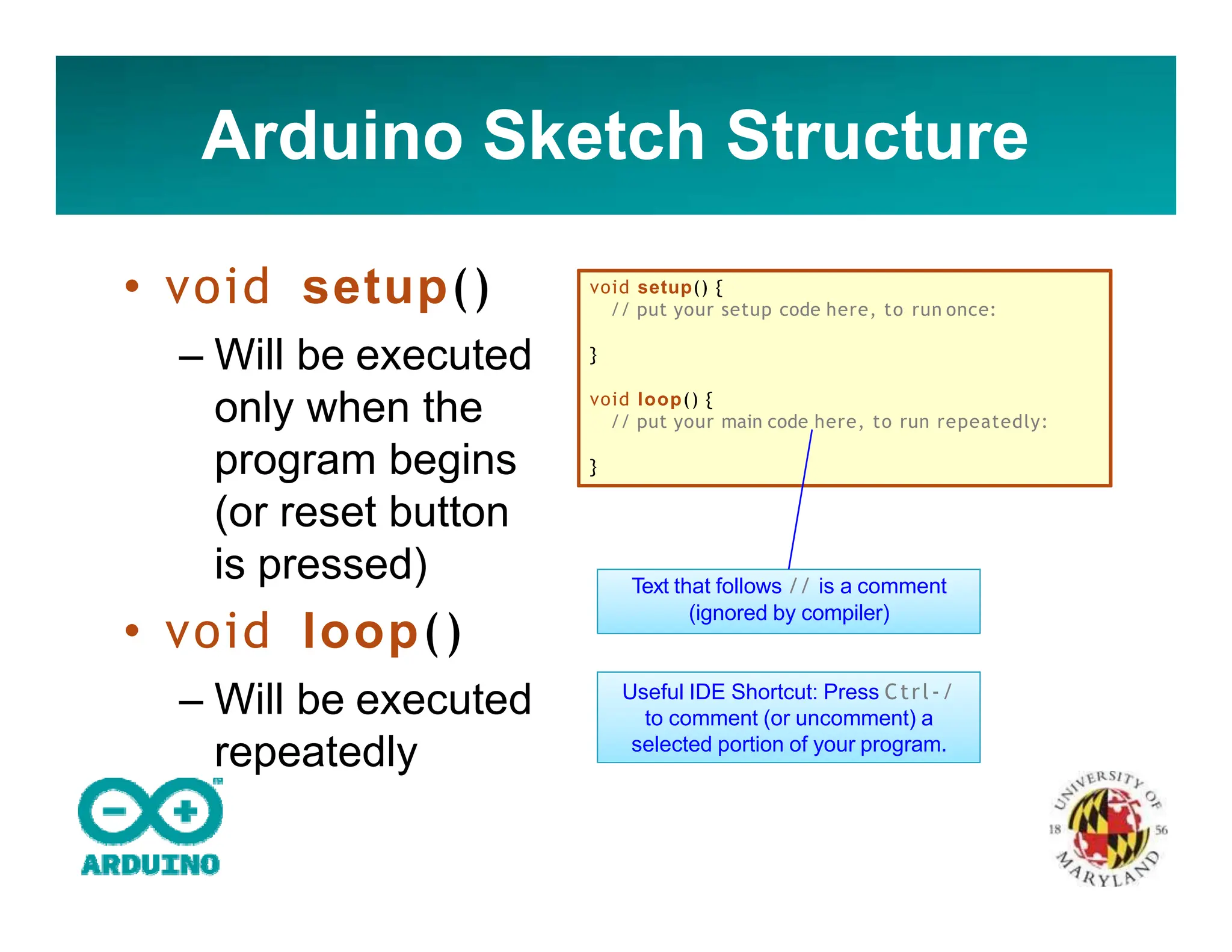
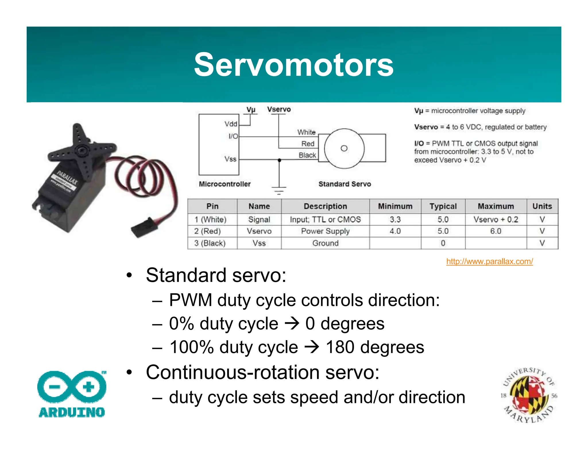
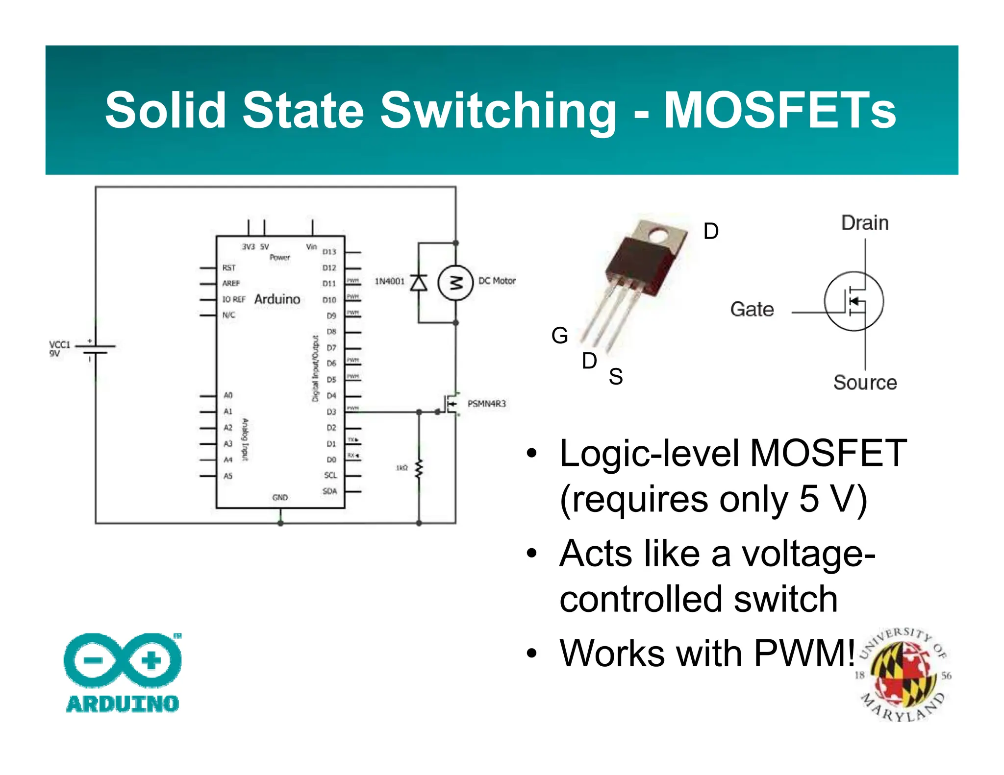
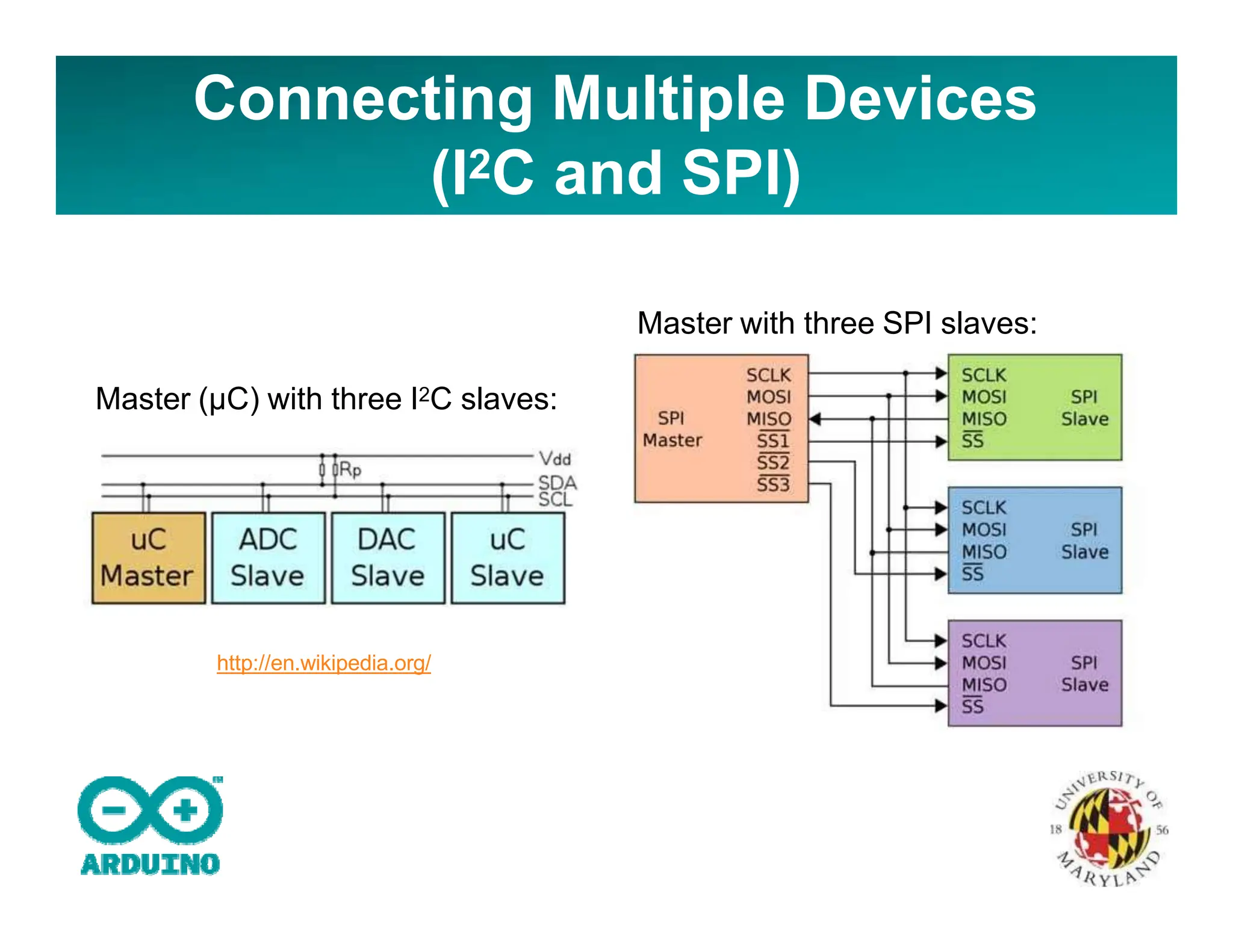
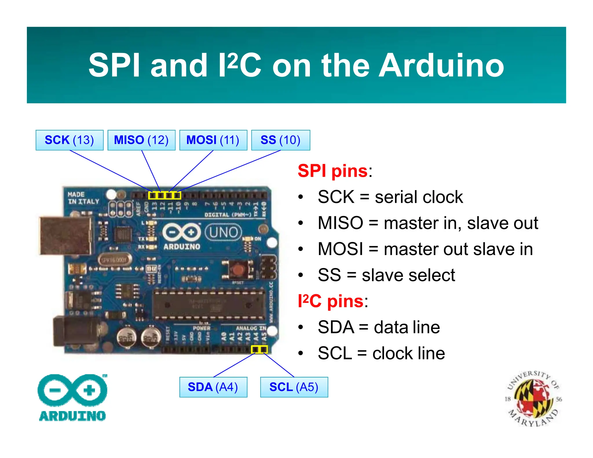
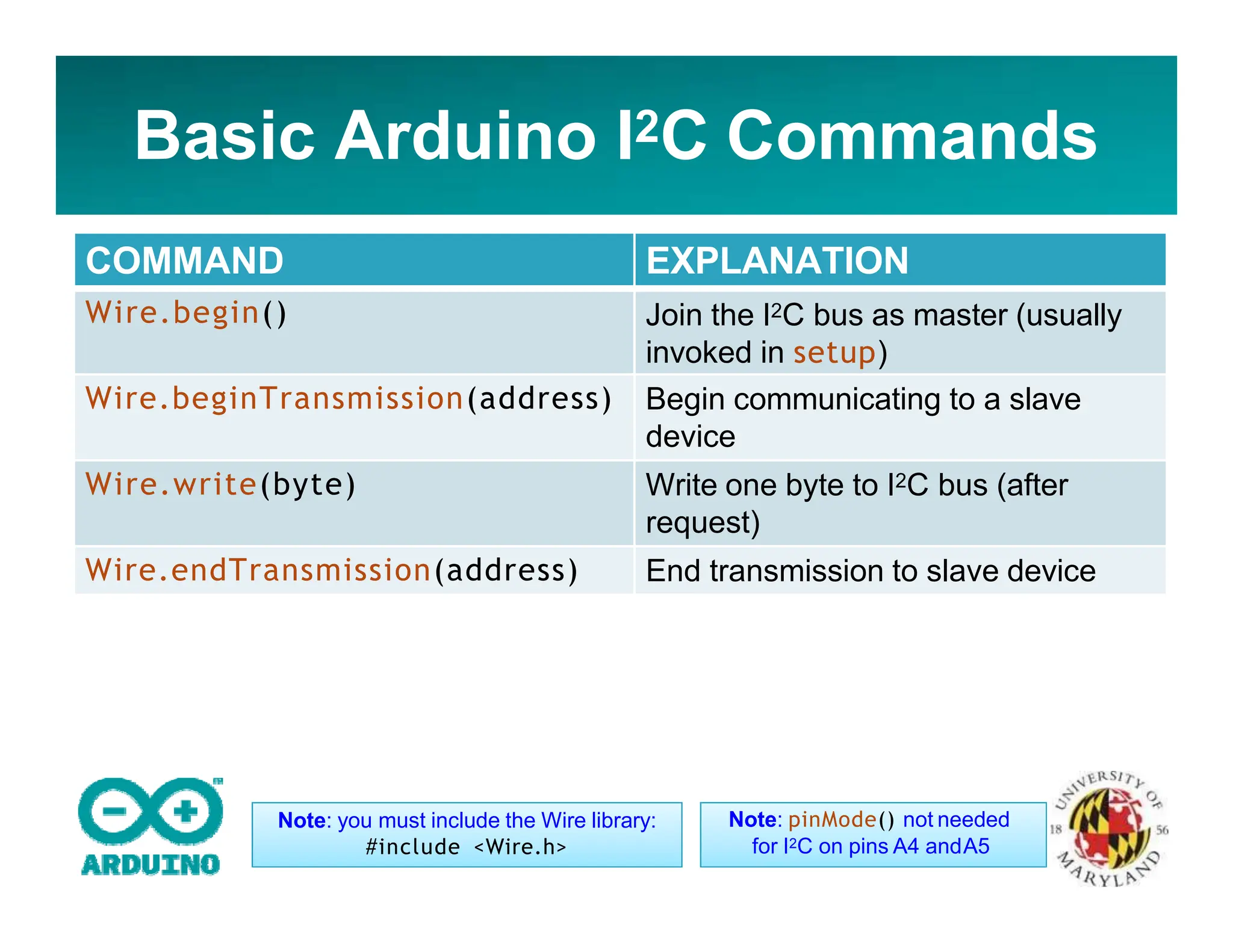
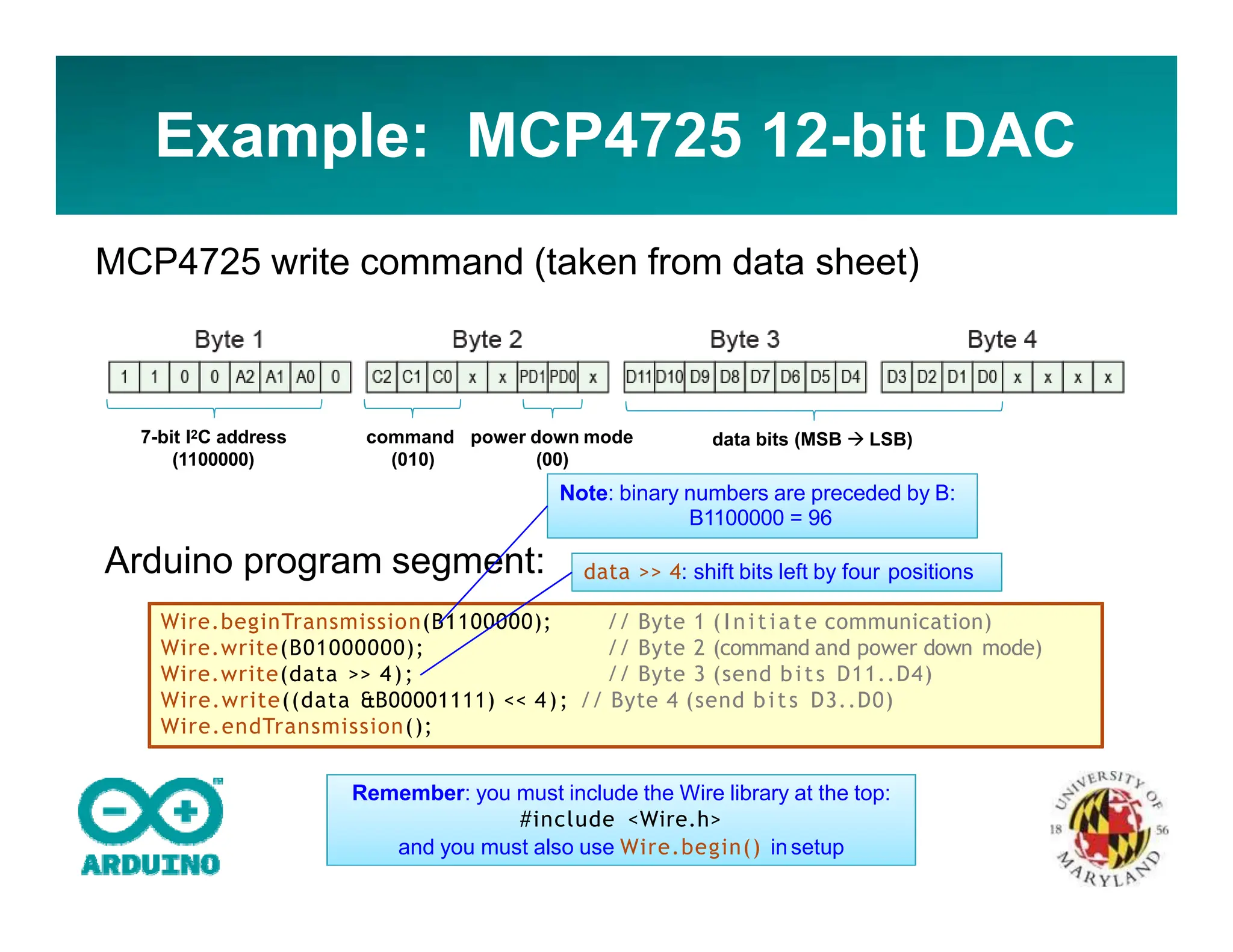
KEMBAR78
Introduction To Arduino-converted for s.pptx
INTRODUCTION TO THE ARDUINO
MICROCONTROLLER
Hands-on Research in Complex Systems
Shanghai Jiao Tong University
June 17 – 29, 2012
Instructor: Thomas E. Murphy (University of Maryland)
Assisted by: Hien Dao (UMD), Caitlin Williams (UMD) and
徐浩 (SJTU)
What is a Microcontroller
(µC, MCU)
• Computer on a single integrated chip
– Processor (CPU)
– Memory (RAM / ROM / Flash)
– I/O ports (USB, I2C, SPI,ADC)
• Common microcontroller families:
– Intel: 4004, 8008, etc.
– Atmel: AT andAVR
– Microchip: PIC
– ARM: (multiple manufacturers)
• Used in:
– Cellphones,
– Toys
– Household appliances
– Cars
– Cameras
The ATmega328P Microcontroller
(used by the Arduino)
• AVR 8-bit RISC architecture
• Available in DIP package
• Up to 20 MHz clock
• 32kB flash memory
• 1 kB SRAM
• 23 programmable I/O
channels
• Six 10-bit ADC inputs
• Three timers/counters
• Six PWM outputs
What is Arduino Not?
• It is not a chip (IC)
• It is not a board (PCB)
• It is not a company or a manufacturer
• It is not a programming language
• It is not a computer architecture
(although it involves all of these things...)
So what is Arduino?
It’s a movement, not a microcontroller:
• Founded by Massimo Banzi and David
Cuartielles in 2005
• Based on “Wiring Platform”, which dates to
2003
• Open-source hardware platform
• Open source development environment
– Easy-to learn language and libraries (based
on Wiring language)
– Integrated development environment (based
on Processing programming environment)
– Available for Windows / Mac / Linux
The Many Flavors of Arduino
• Arduino Uno
• Arduino Leonardo
• Arduino LilyPad
• Arduino Mega
• Arduino Nano
• Arduino Mini
• Arduino Mini Pro
• Arduino BT
Arduino-like Systems
• Cortino (ARM)
• Xduino (ARM)
• LeafLabs Maple
(ARM)
• BeagleBoard (Linux)
• Wiring Board
(Arduino
predecessor)
Arduino Add-ons (Shields)
• TFT Touch Screen
• Data logger
• Motor/Servo shield
• Ethernet shield
• Audio wave shield
• Cellular/GSM shield
• WiFi shield
• Proto-shield
• ...many more
Where to Get an Arduino Board
• Purchase from online vendor (available
worldwide)
– Sparkfun
– Adafruit
– DFRobot
• ... or build your own
– PC board
– Solderless breadboard
http://itp.nyu.edu/physcomp/Tutorials/ArduinoBreadboard
Getting to know the Arduino:
Electrical Inputs and Outputs
14 digital inputs/outputs
(6 PWM outputs)
6 analog
inputs
DC voltage
supply
(IN/OUT)
USB connection
AC/DC adapter
jack
• Input voltage: 7-12 V
(USB, DC plug, or Vin)
• Max output current per pin: 40 mA
ATmega328P
16 MHz clock
Voltage regulator
LED
Reset
Button
Power
indicator
Download and Install
• Download Arduino compiler and development environment from:
http://arduino.cc/en/Main/Software
• Current version: 1.0.1
• Available for:
– Windows
– MacOX
– Linux
• No installer needed... just unzip to a convenient location
• Before running Arduino, plug in your board using USB cable
(external power is not necessary)
• When USB device is not recognized, navigate to and select the
appopriate driver from the installation directory
• Run Arduino
Select your Board
Select Serial Port
Elements of the Arduino IDE
• Text editor
– syntax and keyword
coloring
– automatic
indentation
– programming
shortcuts
• Compiler
• Hardware Interface
– Uploading programs
– Communicating with
Arduino via USB
Using the Arduino IDE
Name of sketch
Compile sketch
Upload to board
New
Open
Save
Serial Monitor
Program area
Messages /
Errors
Arduino Reference
Arduino Reference is installed locally
or available online at http://arduino.cc/
Arduino Sketch Structure
• void setup()
– Will be executed
only when the
program begins
(or reset button
is pressed)
• void loop()
– Will be executed
repeatedly
void setup() {
// put your setup code here, to run once:
}
void loop() {
// put your main code here, to run repeatedly:
}
Text that follows // is a comment
(ignored by compiler)
Useful IDE Shortcut: Press Ctrl‐/
to comment (or uncomment) a
selected portion of your program.
• Load the “Blink” example
(FileExamplesBasicsBlink)
Activity 1: LED Blink
void setup() {
// i n i t i a li ze the digital pin as an output.
// Pin 13 has an LED connected on most Arduino boards:
pinMode(13, OUTPUT);
}
// set the LED on
// wait for a second
// set the LED off
// wait for a second
void loop() {
digitalWrite(13, HIGH);
delay(1000);
digitalWrite(13, LOW);
delay(1000);
}
• Compile, then upload the program
• Congratulations! you are now blinkers!
Use pin 13 as digital output
Set output high (+5V)
Wait 1000 milliseconds
Set output low (0V)
Now connect your own LED
Anatomy of an LED:
http://www.wikipedia.org/
Notes:
• Resistor is needed to limit current
• Resistor and LED may be
interchanged
(but polarity of LED is important)
• Pin 13 is special: has built-in
resistor and LED
• Change program and upload
Aside: Using a Solderless
Breadboard
Connected together
Connected together
300 mils
Example: Using a Solderless
Breadboard
• Change the blink rate
– how fast can the LED blink (before you can
no longer perceive the blinking?)
• How would you make the LED dimmer?
– (...without changing the resistor?)
Experimenting
Digital Input: Reading Switches
and Buttons
// Use pin 11 for digital out
// Use pin 12 for digital input
// Enable pull‐up resistor
void setup() {
pinMode(11, OUTPUT);
pinMode(12, INPUT);
digitalWrite(12, HIGH);
}
// read state of pin 12
// set state of pin 11 (LED)
// wait for a 1/10 second
void loop() {
boolean state;
state = digitalRead(12);
digitalWrite(11, state);
delay(100);
}
Writing HIGH to an input pin:
enables an internal pull-up resistor
• Turn on/off LED based on switch
• Pin 12 reads LOWwhen switch is closed
• Pin 12 reads HIGH when switch is open (pull-up)
Without the internal pull-up resistor,
unconnected digital inputs could
read either high or low
Activity 2: Seven-Segment
Display
• Write a that program that counts from 0 to
9 and displays the result on a seven-
segment LED display
• Consider writing a function:
void writeDigit(int n)
that writes a single digit
Seven-Segment Display Table
Digit ABCDEF
G
A B C D E F G
0 0×7E on on on on on on off
1 0×30 off on on off off off off
2 0×6D on on off on on off on
3 0×79 on on on on off off on
4 0×33 off on on off off on on
5 0×5B on off on on off on on
6 0×5F on off on on on on on
7 0×70 on on on off off off off
8 0×7F on on on on on on on
9 0×7B on on on on off on on
Useful:
• bitRead(x,n)
Get the value of the nth bit of an integer x
Example:
– bitRead(0x7E,7); // returns 1 (see table above)
Serial Communication - Writing
• Serial.begin(baud)
Initialize serial port for communication (and sets baud
rate)
Example:
– Serial.begin(9600); // 9600 baud
• Serial.print(val), Serial.print(val,fmt)
Prints data to the serial port
Examples:
– Serial.print(“Hi”); // print a string
– Serial.print(78); // works with numbers, too
– Serial.print(variable); // works with variables
– Serial.print(78,BIN); // will print 1001110
• Serial.println(val)
Same as Serial.print(), but withline-feed
Note: Serial.end() command
is usually unnecessary, unless
you need to use pins 0 & 1
IMPORTANT:
USB serial
communication is
shared with
Arduino pins 0
and 1 (RX/TX)
Format can be:
BIN, HEX, OCT,
or an integer
specifying the
number of digits
to display
Activity 3: Hello World!
• Write an Arduino
program that prints the
message “Hello world”
to the serial port
• ...whenever you press
a switch/button
• Use the Serial Monitor
to see the output
(Ctrl-Shift-M)
• Try increasing baud
rate
Serial Monitor:
Make sure this agrees with your
program, i.e., Serial.begin(9600);
Serial Communication - Reading
• Serial.available()
Returns the number of bytes available to be read, if any
Example:
i f (Serial.available() > 0) {
data = Serial.read();
}
To read data from serial port:
•
•
•
•
letter = Serial.read()
letters = Serial.readBytesUntil(character, buffer, length)
number = Serial.parseInt()
number = Serial.parseFloat( )
Activity 4 – User Controlled
Blinker
• When available (Serial.available), read an integer
from the serial port (Serial.parseInt), and use the
result to change the blink rate of the LED (pin 13)
Useful:
• constrain(x,a,b)
Constrains the variable x to be from a to b
Examples:
– constrain(5,1,10); // returns 5
– constrain(50,1,10); // returns 10
– constrain(0,1,10); // returns 1
Analog Input and Sensors
• Six analog inputs:
A0, A1, A2, A3, A4, A5
• AREF = Reference voltage
(default = +5 V)
• 10 bit resolution:
– returns an integer from 0 to
1023
– result is proportional to the
pin voltage
• All voltages are measured
relative to GND
Analog Inputs
Reference Voltage (optional)
Note: If you need additional
digital I/O, the analog pins can be
re-assigned for digital use:
pinMode(A0, OUTPUT);
Reading Analog Values
• value = analogRead(pin)
Reads the analog measurement on pin
Returns integer between 0 and 1023
• analogReference(type)
type can be:
– DEFAULT - the default analog reference of 5 volts (on
5V Arduino boards)
– INTERNAL – Built-in reference voltage (1.1 V)
– EXTERNAL – AREF input pin
Note: Do NOT use pinMode(A0, INPUT) unless you want to
use A0 for DIGITAL input.
Aside: Potentiometers
(variable resistors, rheostats)
Activity 5 – Volume Knob
• Connect the potentiometer from 5V to GND
• Use analogRead(A0) to measure the voltage on the center pin
• Set the LED blink rate depending on the reading
Activity 6 – Arduino
Thermometer
• Build a circuit and write a sketch to
read and report the temperature at
1 second intervals
Data Logging Ideas
• m i l l i s ( )
Returns the number of milliseconds elapsed since
program started (or reset)
Time functions
• setTime(hr,min,sec,day,month,yr)
• hour(), minute(), day(), month(), year()
Real-time Clock (RTC):
• Use an external, battery-powered chip (e.g., DS1307) to
provide clock
Note: this uses the Time library:
#include <Time.h>
Activity 7 – Arduino Nightlight
• CdS Photoresistor:
resistance depends on ambient
light level
• Build a circuit and write a sketch that turns
on an LED whenever it gets dark
Hint: connect the photoresistor in a voltage
divider
Analog Output?
• Most microcontrollers have
only digital outputs
• Pulse-width Modulation:
Analog variables can be
represented by the duty-
cycle (or pulse-width) of a
digital signal
http://arduino.cc/en/Tutorial/PWM
PulseWidth Modulation (PWM)
• analogWrite(pin,val)
set the PWM fraction:
– val = 0: always off
– val = 255: always on
• Remember to designate pin
for digital output:
pinMode(pin,OUTPUT);
(usually in setup)
• Default PWM frequency:
– 16 MHz / 215 = 488.28125 Hz
PWM available on pins 3, 5, 6, 9, 10, 11
Note: the PWM frequency and
resolution can be changed by
re-configuring the timers
Activity 8 – PWM LED Dimmer
• Use PWM to control the brightness of an LED
– connect LED to pin 3, 5, 6, 9, 10 or 11
– remember to use 220 Ω current-limiting resistor
• Set the brightness from the serial port, or
potentiometer
• Watch the output on an oscilloscope
Useful:
• newValue = map(oldValue, a, b, c, d)
Converts/maps a number in the range (a:b) to a new number in
the range (c:d)
Example:
– newValue = map(oldValue,0,1023,0,255);
• Change your program to sinusoidally
modulate the intensity of the LED, at a 1
Hz rate
– Hint: use the millis(), s i n ( ) , and
analogWrite() functions
Activity 8 – PWM LED Dimmer
(cont’d)
Servomotors
• Standard servo:
– PWM duty cycle controls direction:
– 0% duty cycle  0 degrees
– 100% duty cycle  180 degrees
• Continuous-rotation servo:
– duty cycle sets speed and/or direction
http://www.parallax.com/
Activity 9 – Servomotor Control
• Build a program that turns a servomotor
from 0 to 180 degrees, based on
potentiometer reading
• Report setting to the serial monitor
Solid State Switching - MOSFETs
G
D
S
D
• Logic-level MOSFET
(requires only 5 V)
• Acts like a voltage-
controlled switch
• Works with PWM!
Activity 10 – PWM Speed Control
• Build a circuit to control the speed of a
motor using a PWM-controlled MOSFET
• Enter the speed (PWM setting) from the
serial port (Serial.parseInt)
Controlling Relays and
Solenoids
• Electromechanically
-actuated switch
• Provides electrical
isolation
• Typically few ms
response time
Note: Arduino cannot supply
enough current to drive relay coil
Relay Driver Circuit
• NPN transistor: acts like a current-controlled switch
• MOSFET will also work
• Diode prevents back-EMF (associated with inductive
loads)
• Coil voltage supply and Arduino share common GND
Activity 11: Bidirectional Motor
Driver
• Build a circuit (and write an Arduino
sketch) that will use a DPDT relay to
change the direction of a DC motor:
Note: this is called an H-bridge circuit.
It can also be made with transistors
Communication: I2C, SPI
• I2C (Inter-Integrated Circuit)
– Developed by Phillips
– Speed = 100 kHz, 400 kHz, and 3.4 MHz (not
supported by Arduino)
– Two bi-directional lines: SDA, SCL
– Multiple slaves can share same bus
• SPI (Serial Peripheral Interface Bus)
– Speed = 1-100 MHz (clock/device limited)
– Four-wire bus: SCLK, MOSI, MISO, SS
– Multiple slaves can share same bus
(but each needs a dedicated SS, slave select)
Connecting Multiple Devices
(I2C and SPI)
http://en.wikipedia.org/
Master with three SPI slaves:
Master (µC) with three I2C slaves:
SPI and I2C on the Arduino
SPI pins:
• SCK = serial clock
• MISO = master in, slave out
• MOSI = master out slave in
• SS = slave select
I2C pins:
• SDA = data line
• SCL = clock line
SS (10)
MOSI (11)
MISO (12)
SCK (13)
SDA (A4) SCL (A5)
Basic Arduino I2C Commands
COMMAND EXPLANATION
Wire.begin() Join the I2C bus as master (usually
invoked in setup)
Wire.beginTransmission(address) Begin communicating to a slave
device
Wire.write(byte) Write one byte to I2C bus (after
request)
Wire.endTransmission(address) End transmission to slave device
Note: you must include the Wire library:
#include <Wire.h>
Note: pinMode() not needed
for I2C on pins A4 andA5
Example: MCP4725 12-bit DAC
MCP4725 write command (taken from data sheet)
7-bit I2C address
(1100000)
command power down mode
(010) (00)
data bits (MSB  LSB)
Wire.beginTransmission(B1100000);
Wire.write(B01000000);
Wire.write(data >> 4);
// Byte 1 (Initiate communication)
// Byte 2 (command and power down mode)
// Byte 3 (send bits D11..D4)
Arduino program segment:
Note: binary numbers are preceded by B:
B1100000 = 96
Wire.write((data &B00001111) << 4); // Byte 4 (send bits D3..D0)
Wire.endTransmission();
Remember: you must include the Wire library at the top:
#include <Wire.h>
and you must also use Wire.begin() insetup
data >> 4: shift bits left by four positions
Additional I2C Commands
COMMAND EXPLANATION
Wire.begin() Join the I2C bus as master (usually invoked
in setup)
Wire.begin(address) Join the I2C bus as slave, with address
specified (usually invoked in setup)
Wire.beginTransmission(address) Begin communicating to a slave device
Wire.write(byte) Write one byte to I2C bus (after request)
Wire.write(bytes,length) Write length bytes to I2C bus
Wire.endTransmission(address) End transmission to slave device
Wire.requestFrom(address, quantity)
Wire.requestFrom(address, quantity, stop)
Request bytes (quantity) from slave
Wire.available() The number of bytes available for reading
Wire.read() Reads a byte that was transmitted from a
slave. (Preceded by Wire.requestFrom)
Note: you must include the Wire library:
#include <Wire.h>
Note: pinMode() not needed
for I2C on pins A4 andA5
Activity 12: Sawtooth Wave
• Program the MCP4725 DAC to produce a
sawtooth (ramp) wave:
– What is the frequency of the sawtooth wave?
– Can you make f = 100 Hz?
Note: the I2C bus requires pull-
up resistors on SCL and SDA
(provided on the board)
MCP4725
breakout
board:
http://www.sparkfun.com/
Basic Arduino SPI Commands
COMMAND EXPLANATION
SPI.begin() Initializes the SPI bus, setting SCK,
MOSI, and SS to outputs, pulling
SCK and MOSI low and SS high.
byteIn = SPI.transfer(byteOut) Transfer one byte (both send and
receive) returns the received byte
Note: you must include the SPI library:
#include <SPI.h>
Note: pinMode() not needed. It is
automatically configured in SPI.begin()
Additional Arduino SPI
Commands
COMMAND EXPLANATION
SPI.begin() Initializes the SPI bus, setting SCK, MOSI, and SS to
outputs, pulling SCK and MOSI low and SS high.
SPI.end() Disables the SPI bus (leaving pin modes unchanged) – in
case you need to use pins 10-13 again
SPI.setBitOrder(order) Set bit order for SPI
order = {LSBFIRST, MSBFIRST}
SPI.setClockDivider(divider) Set the SPI clock divider
divider = {2, 4, 8, 16, 32, 64, 128}
SPI clock speed = 16 MHz/divider
SPI.setDataMode(mode) Set the SPI data mode
mode = {SPI_MODE0, SPI_MODE1, SPI_MODE2, SPI_MODE3}
SPI.transfer(byte) Transfer one byte (both send and receive)
returns the received byte
Note: you must include the SPI library:
#include <SPI.h>
Note: pinMode() not needed
Example: AD5206 Digital
Potentiometer
Features:
• six independent, 3-
wiper potentiometers
• 8-bit precision
(256 possible levels)
• Available in 10kΩ,
50kΩ and 100kΩ
• Programmed
through SPI interface
Functional block diagram:
AD5206 Write Sequence
SPI.begin(); // in it ia lize SPI ( in setup)
. . .
digitalWrite(SS,LOW); // hold SS pin low to select chip
SPI.transfer(potnumber); // determine which pot (0..5)
SPI.transfer(wipervalue); // transfer 8‐bit wiper setting
digitalWrite(SS,HIGH); // de‐select the chip
Arduino program segment:
Note: same as SS
(slave select)
Note: same as MOSI
(master out slave in)
Activity 13: Programmable
Voltage Divider
• Use the AD5206 to build a programmable
voltage divider
• Allow the user to set the resistance from
the serial port
• Measure resistance with an Ohm meter,
or using analogRead()
AD5206: Summary of Pins and
Commands
SCK (13) MISO (12) MOSI (11) SS (10)
digitalWrite(SS,LOW); // hold SS pin low to select chip
SPI.transfer(potnumber); // determine which pot (0..5)
SPI.transfer(wipervalue); // transfer 8‐bit wiper setting
digitalWrite(SS,HIGH); // de‐select the chip
Remember: SPI.begin() needed in setup() and #include <SPI.h>

Introduction To Arduino-converted for s.pptx

  • 1.
    INTRODUCTION TO THEARDUINO MICROCONTROLLER Hands-on Research in Complex Systems Shanghai Jiao Tong University June 17 – 29, 2012 Instructor: Thomas E. Murphy (University of Maryland) Assisted by: Hien Dao (UMD), Caitlin Williams (UMD) and 徐浩 (SJTU)
  • 2.
    What is aMicrocontroller (µC, MCU) • Computer on a single integrated chip – Processor (CPU) – Memory (RAM / ROM / Flash) – I/O ports (USB, I2C, SPI,ADC) • Common microcontroller families: – Intel: 4004, 8008, etc. – Atmel: AT andAVR – Microchip: PIC – ARM: (multiple manufacturers) • Used in: – Cellphones, – Toys – Household appliances – Cars – Cameras
  • 3.
    The ATmega328P Microcontroller (usedby the Arduino) • AVR 8-bit RISC architecture • Available in DIP package • Up to 20 MHz clock • 32kB flash memory • 1 kB SRAM • 23 programmable I/O channels • Six 10-bit ADC inputs • Three timers/counters • Six PWM outputs
  • 4.
    What is ArduinoNot? • It is not a chip (IC) • It is not a board (PCB) • It is not a company or a manufacturer • It is not a programming language • It is not a computer architecture (although it involves all of these things...)
  • 5.
    So what isArduino? It’s a movement, not a microcontroller: • Founded by Massimo Banzi and David Cuartielles in 2005 • Based on “Wiring Platform”, which dates to 2003 • Open-source hardware platform • Open source development environment – Easy-to learn language and libraries (based on Wiring language) – Integrated development environment (based on Processing programming environment) – Available for Windows / Mac / Linux
  • 6.
    The Many Flavorsof Arduino • Arduino Uno • Arduino Leonardo • Arduino LilyPad • Arduino Mega • Arduino Nano • Arduino Mini • Arduino Mini Pro • Arduino BT
  • 7.
    Arduino-like Systems • Cortino(ARM) • Xduino (ARM) • LeafLabs Maple (ARM) • BeagleBoard (Linux) • Wiring Board (Arduino predecessor)
  • 8.
    Arduino Add-ons (Shields) •TFT Touch Screen • Data logger • Motor/Servo shield • Ethernet shield • Audio wave shield • Cellular/GSM shield • WiFi shield • Proto-shield • ...many more
  • 9.
    Where to Getan Arduino Board • Purchase from online vendor (available worldwide) – Sparkfun – Adafruit – DFRobot • ... or build your own – PC board – Solderless breadboard http://itp.nyu.edu/physcomp/Tutorials/ArduinoBreadboard
  • 10.
    Getting to knowthe Arduino: Electrical Inputs and Outputs 14 digital inputs/outputs (6 PWM outputs) 6 analog inputs DC voltage supply (IN/OUT) USB connection AC/DC adapter jack • Input voltage: 7-12 V (USB, DC plug, or Vin) • Max output current per pin: 40 mA ATmega328P 16 MHz clock Voltage regulator LED Reset Button Power indicator
  • 11.
    Download and Install •Download Arduino compiler and development environment from: http://arduino.cc/en/Main/Software • Current version: 1.0.1 • Available for: – Windows – MacOX – Linux • No installer needed... just unzip to a convenient location • Before running Arduino, plug in your board using USB cable (external power is not necessary) • When USB device is not recognized, navigate to and select the appopriate driver from the installation directory • Run Arduino
  • 12.
  • 13.
  • 14.
    Elements of theArduino IDE • Text editor – syntax and keyword coloring – automatic indentation – programming shortcuts • Compiler • Hardware Interface – Uploading programs – Communicating with Arduino via USB
  • 15.
    Using the ArduinoIDE Name of sketch Compile sketch Upload to board New Open Save Serial Monitor Program area Messages / Errors
  • 16.
    Arduino Reference Arduino Referenceis installed locally or available online at http://arduino.cc/
  • 17.
    Arduino Sketch Structure •void setup() – Will be executed only when the program begins (or reset button is pressed) • void loop() – Will be executed repeatedly void setup() { // put your setup code here, to run once: } void loop() { // put your main code here, to run repeatedly: } Text that follows // is a comment (ignored by compiler) Useful IDE Shortcut: Press Ctrl‐/ to comment (or uncomment) a selected portion of your program.
  • 18.
    • Load the“Blink” example (FileExamplesBasicsBlink) Activity 1: LED Blink void setup() { // i n i t i a li ze the digital pin as an output. // Pin 13 has an LED connected on most Arduino boards: pinMode(13, OUTPUT); } // set the LED on // wait for a second // set the LED off // wait for a second void loop() { digitalWrite(13, HIGH); delay(1000); digitalWrite(13, LOW); delay(1000); } • Compile, then upload the program • Congratulations! you are now blinkers! Use pin 13 as digital output Set output high (+5V) Wait 1000 milliseconds Set output low (0V)
  • 19.
    Now connect yourown LED Anatomy of an LED: http://www.wikipedia.org/ Notes: • Resistor is needed to limit current • Resistor and LED may be interchanged (but polarity of LED is important) • Pin 13 is special: has built-in resistor and LED • Change program and upload
  • 20.
    Aside: Using aSolderless Breadboard Connected together Connected together 300 mils
  • 21.
    Example: Using aSolderless Breadboard
  • 22.
    • Change theblink rate – how fast can the LED blink (before you can no longer perceive the blinking?) • How would you make the LED dimmer? – (...without changing the resistor?) Experimenting
  • 23.
    Digital Input: ReadingSwitches and Buttons // Use pin 11 for digital out // Use pin 12 for digital input // Enable pull‐up resistor void setup() { pinMode(11, OUTPUT); pinMode(12, INPUT); digitalWrite(12, HIGH); } // read state of pin 12 // set state of pin 11 (LED) // wait for a 1/10 second void loop() { boolean state; state = digitalRead(12); digitalWrite(11, state); delay(100); } Writing HIGH to an input pin: enables an internal pull-up resistor • Turn on/off LED based on switch • Pin 12 reads LOWwhen switch is closed • Pin 12 reads HIGH when switch is open (pull-up) Without the internal pull-up resistor, unconnected digital inputs could read either high or low
  • 24.
    Activity 2: Seven-Segment Display •Write a that program that counts from 0 to 9 and displays the result on a seven- segment LED display • Consider writing a function: void writeDigit(int n) that writes a single digit
  • 25.
    Seven-Segment Display Table DigitABCDEF G A B C D E F G 0 0×7E on on on on on on off 1 0×30 off on on off off off off 2 0×6D on on off on on off on 3 0×79 on on on on off off on 4 0×33 off on on off off on on 5 0×5B on off on on off on on 6 0×5F on off on on on on on 7 0×70 on on on off off off off 8 0×7F on on on on on on on 9 0×7B on on on on off on on Useful: • bitRead(x,n) Get the value of the nth bit of an integer x Example: – bitRead(0x7E,7); // returns 1 (see table above)
  • 26.
    Serial Communication -Writing • Serial.begin(baud) Initialize serial port for communication (and sets baud rate) Example: – Serial.begin(9600); // 9600 baud • Serial.print(val), Serial.print(val,fmt) Prints data to the serial port Examples: – Serial.print(“Hi”); // print a string – Serial.print(78); // works with numbers, too – Serial.print(variable); // works with variables – Serial.print(78,BIN); // will print 1001110 • Serial.println(val) Same as Serial.print(), but withline-feed Note: Serial.end() command is usually unnecessary, unless you need to use pins 0 & 1 IMPORTANT: USB serial communication is shared with Arduino pins 0 and 1 (RX/TX) Format can be: BIN, HEX, OCT, or an integer specifying the number of digits to display
  • 27.
    Activity 3: HelloWorld! • Write an Arduino program that prints the message “Hello world” to the serial port • ...whenever you press a switch/button • Use the Serial Monitor to see the output (Ctrl-Shift-M) • Try increasing baud rate Serial Monitor: Make sure this agrees with your program, i.e., Serial.begin(9600);
  • 28.
    Serial Communication -Reading • Serial.available() Returns the number of bytes available to be read, if any Example: i f (Serial.available() > 0) { data = Serial.read(); } To read data from serial port: • • • • letter = Serial.read() letters = Serial.readBytesUntil(character, buffer, length) number = Serial.parseInt() number = Serial.parseFloat( )
  • 29.
    Activity 4 –User Controlled Blinker • When available (Serial.available), read an integer from the serial port (Serial.parseInt), and use the result to change the blink rate of the LED (pin 13) Useful: • constrain(x,a,b) Constrains the variable x to be from a to b Examples: – constrain(5,1,10); // returns 5 – constrain(50,1,10); // returns 10 – constrain(0,1,10); // returns 1
  • 30.
    Analog Input andSensors • Six analog inputs: A0, A1, A2, A3, A4, A5 • AREF = Reference voltage (default = +5 V) • 10 bit resolution: – returns an integer from 0 to 1023 – result is proportional to the pin voltage • All voltages are measured relative to GND Analog Inputs Reference Voltage (optional) Note: If you need additional digital I/O, the analog pins can be re-assigned for digital use: pinMode(A0, OUTPUT);
  • 31.
    Reading Analog Values •value = analogRead(pin) Reads the analog measurement on pin Returns integer between 0 and 1023 • analogReference(type) type can be: – DEFAULT - the default analog reference of 5 volts (on 5V Arduino boards) – INTERNAL – Built-in reference voltage (1.1 V) – EXTERNAL – AREF input pin Note: Do NOT use pinMode(A0, INPUT) unless you want to use A0 for DIGITAL input.
  • 32.
  • 33.
    Activity 5 –Volume Knob • Connect the potentiometer from 5V to GND • Use analogRead(A0) to measure the voltage on the center pin • Set the LED blink rate depending on the reading
  • 34.
    Activity 6 –Arduino Thermometer • Build a circuit and write a sketch to read and report the temperature at 1 second intervals
  • 35.
    Data Logging Ideas •m i l l i s ( ) Returns the number of milliseconds elapsed since program started (or reset) Time functions • setTime(hr,min,sec,day,month,yr) • hour(), minute(), day(), month(), year() Real-time Clock (RTC): • Use an external, battery-powered chip (e.g., DS1307) to provide clock Note: this uses the Time library: #include <Time.h>
  • 36.
    Activity 7 –Arduino Nightlight • CdS Photoresistor: resistance depends on ambient light level • Build a circuit and write a sketch that turns on an LED whenever it gets dark Hint: connect the photoresistor in a voltage divider
  • 37.
    Analog Output? • Mostmicrocontrollers have only digital outputs • Pulse-width Modulation: Analog variables can be represented by the duty- cycle (or pulse-width) of a digital signal http://arduino.cc/en/Tutorial/PWM
  • 38.
    PulseWidth Modulation (PWM) •analogWrite(pin,val) set the PWM fraction: – val = 0: always off – val = 255: always on • Remember to designate pin for digital output: pinMode(pin,OUTPUT); (usually in setup) • Default PWM frequency: – 16 MHz / 215 = 488.28125 Hz PWM available on pins 3, 5, 6, 9, 10, 11 Note: the PWM frequency and resolution can be changed by re-configuring the timers
  • 39.
    Activity 8 –PWM LED Dimmer • Use PWM to control the brightness of an LED – connect LED to pin 3, 5, 6, 9, 10 or 11 – remember to use 220 Ω current-limiting resistor • Set the brightness from the serial port, or potentiometer • Watch the output on an oscilloscope Useful: • newValue = map(oldValue, a, b, c, d) Converts/maps a number in the range (a:b) to a new number in the range (c:d) Example: – newValue = map(oldValue,0,1023,0,255);
  • 40.
    • Change yourprogram to sinusoidally modulate the intensity of the LED, at a 1 Hz rate – Hint: use the millis(), s i n ( ) , and analogWrite() functions Activity 8 – PWM LED Dimmer (cont’d)
  • 41.
    Servomotors • Standard servo: –PWM duty cycle controls direction: – 0% duty cycle  0 degrees – 100% duty cycle  180 degrees • Continuous-rotation servo: – duty cycle sets speed and/or direction http://www.parallax.com/
  • 42.
    Activity 9 –Servomotor Control • Build a program that turns a servomotor from 0 to 180 degrees, based on potentiometer reading • Report setting to the serial monitor
  • 43.
    Solid State Switching- MOSFETs G D S D • Logic-level MOSFET (requires only 5 V) • Acts like a voltage- controlled switch • Works with PWM!
  • 44.
    Activity 10 –PWM Speed Control • Build a circuit to control the speed of a motor using a PWM-controlled MOSFET • Enter the speed (PWM setting) from the serial port (Serial.parseInt)
  • 45.
    Controlling Relays and Solenoids •Electromechanically -actuated switch • Provides electrical isolation • Typically few ms response time Note: Arduino cannot supply enough current to drive relay coil
  • 46.
    Relay Driver Circuit •NPN transistor: acts like a current-controlled switch • MOSFET will also work • Diode prevents back-EMF (associated with inductive loads) • Coil voltage supply and Arduino share common GND
  • 47.
    Activity 11: BidirectionalMotor Driver • Build a circuit (and write an Arduino sketch) that will use a DPDT relay to change the direction of a DC motor: Note: this is called an H-bridge circuit. It can also be made with transistors
  • 48.
    Communication: I2C, SPI •I2C (Inter-Integrated Circuit) – Developed by Phillips – Speed = 100 kHz, 400 kHz, and 3.4 MHz (not supported by Arduino) – Two bi-directional lines: SDA, SCL – Multiple slaves can share same bus • SPI (Serial Peripheral Interface Bus) – Speed = 1-100 MHz (clock/device limited) – Four-wire bus: SCLK, MOSI, MISO, SS – Multiple slaves can share same bus (but each needs a dedicated SS, slave select)
  • 49.
    Connecting Multiple Devices (I2Cand SPI) http://en.wikipedia.org/ Master with three SPI slaves: Master (µC) with three I2C slaves:
  • 50.
    SPI and I2Con the Arduino SPI pins: • SCK = serial clock • MISO = master in, slave out • MOSI = master out slave in • SS = slave select I2C pins: • SDA = data line • SCL = clock line SS (10) MOSI (11) MISO (12) SCK (13) SDA (A4) SCL (A5)
  • 51.
    Basic Arduino I2CCommands COMMAND EXPLANATION Wire.begin() Join the I2C bus as master (usually invoked in setup) Wire.beginTransmission(address) Begin communicating to a slave device Wire.write(byte) Write one byte to I2C bus (after request) Wire.endTransmission(address) End transmission to slave device Note: you must include the Wire library: #include <Wire.h> Note: pinMode() not needed for I2C on pins A4 andA5
  • 52.
    Example: MCP4725 12-bitDAC MCP4725 write command (taken from data sheet) 7-bit I2C address (1100000) command power down mode (010) (00) data bits (MSB  LSB) Wire.beginTransmission(B1100000); Wire.write(B01000000); Wire.write(data >> 4); // Byte 1 (Initiate communication) // Byte 2 (command and power down mode) // Byte 3 (send bits D11..D4) Arduino program segment: Note: binary numbers are preceded by B: B1100000 = 96 Wire.write((data &B00001111) << 4); // Byte 4 (send bits D3..D0) Wire.endTransmission(); Remember: you must include the Wire library at the top: #include <Wire.h> and you must also use Wire.begin() insetup data >> 4: shift bits left by four positions
  • 53.
    Additional I2C Commands COMMANDEXPLANATION Wire.begin() Join the I2C bus as master (usually invoked in setup) Wire.begin(address) Join the I2C bus as slave, with address specified (usually invoked in setup) Wire.beginTransmission(address) Begin communicating to a slave device Wire.write(byte) Write one byte to I2C bus (after request) Wire.write(bytes,length) Write length bytes to I2C bus Wire.endTransmission(address) End transmission to slave device Wire.requestFrom(address, quantity) Wire.requestFrom(address, quantity, stop) Request bytes (quantity) from slave Wire.available() The number of bytes available for reading Wire.read() Reads a byte that was transmitted from a slave. (Preceded by Wire.requestFrom) Note: you must include the Wire library: #include <Wire.h> Note: pinMode() not needed for I2C on pins A4 andA5
  • 54.
    Activity 12: SawtoothWave • Program the MCP4725 DAC to produce a sawtooth (ramp) wave: – What is the frequency of the sawtooth wave? – Can you make f = 100 Hz? Note: the I2C bus requires pull- up resistors on SCL and SDA (provided on the board) MCP4725 breakout board: http://www.sparkfun.com/
  • 55.
    Basic Arduino SPICommands COMMAND EXPLANATION SPI.begin() Initializes the SPI bus, setting SCK, MOSI, and SS to outputs, pulling SCK and MOSI low and SS high. byteIn = SPI.transfer(byteOut) Transfer one byte (both send and receive) returns the received byte Note: you must include the SPI library: #include <SPI.h> Note: pinMode() not needed. It is automatically configured in SPI.begin()
  • 56.
    Additional Arduino SPI Commands COMMANDEXPLANATION SPI.begin() Initializes the SPI bus, setting SCK, MOSI, and SS to outputs, pulling SCK and MOSI low and SS high. SPI.end() Disables the SPI bus (leaving pin modes unchanged) – in case you need to use pins 10-13 again SPI.setBitOrder(order) Set bit order for SPI order = {LSBFIRST, MSBFIRST} SPI.setClockDivider(divider) Set the SPI clock divider divider = {2, 4, 8, 16, 32, 64, 128} SPI clock speed = 16 MHz/divider SPI.setDataMode(mode) Set the SPI data mode mode = {SPI_MODE0, SPI_MODE1, SPI_MODE2, SPI_MODE3} SPI.transfer(byte) Transfer one byte (both send and receive) returns the received byte Note: you must include the SPI library: #include <SPI.h> Note: pinMode() not needed
  • 57.
    Example: AD5206 Digital Potentiometer Features: •six independent, 3- wiper potentiometers • 8-bit precision (256 possible levels) • Available in 10kΩ, 50kΩ and 100kΩ • Programmed through SPI interface Functional block diagram:
  • 58.
    AD5206 Write Sequence SPI.begin();// in it ia lize SPI ( in setup) . . . digitalWrite(SS,LOW); // hold SS pin low to select chip SPI.transfer(potnumber); // determine which pot (0..5) SPI.transfer(wipervalue); // transfer 8‐bit wiper setting digitalWrite(SS,HIGH); // de‐select the chip Arduino program segment: Note: same as SS (slave select) Note: same as MOSI (master out slave in)
  • 59.
    Activity 13: Programmable VoltageDivider • Use the AD5206 to build a programmable voltage divider • Allow the user to set the resistance from the serial port • Measure resistance with an Ohm meter, or using analogRead()
  • 60.
    AD5206: Summary ofPins and Commands SCK (13) MISO (12) MOSI (11) SS (10) digitalWrite(SS,LOW); // hold SS pin low to select chip SPI.transfer(potnumber); // determine which pot (0..5) SPI.transfer(wipervalue); // transfer 8‐bit wiper setting digitalWrite(SS,HIGH); // de‐select the chip Remember: SPI.begin() needed in setup() and #include <SPI.h>