Download as PDF, PPTX


The document discusses container networking and microservices architecture, highlighting the need for service discovery, load balancing, and multi-tenancy in cloud environments. It explains how containers are lightweight units of software that help reduce conflicts in development environments, while microservices allow for autonomous and scalable applications. Additionally, it elaborates on networking models such as CNM and CNI, which facilitate container communication and management, particularly in platforms like Docker and Kubernetes.
Introduction to the speaker and their experience in container and networking technologies.
An overview of the presentation agenda focusing on containers, microservices, and related topics.
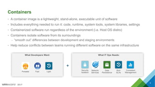
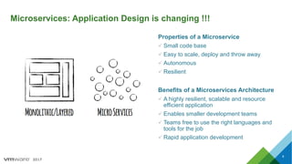
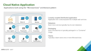
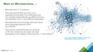
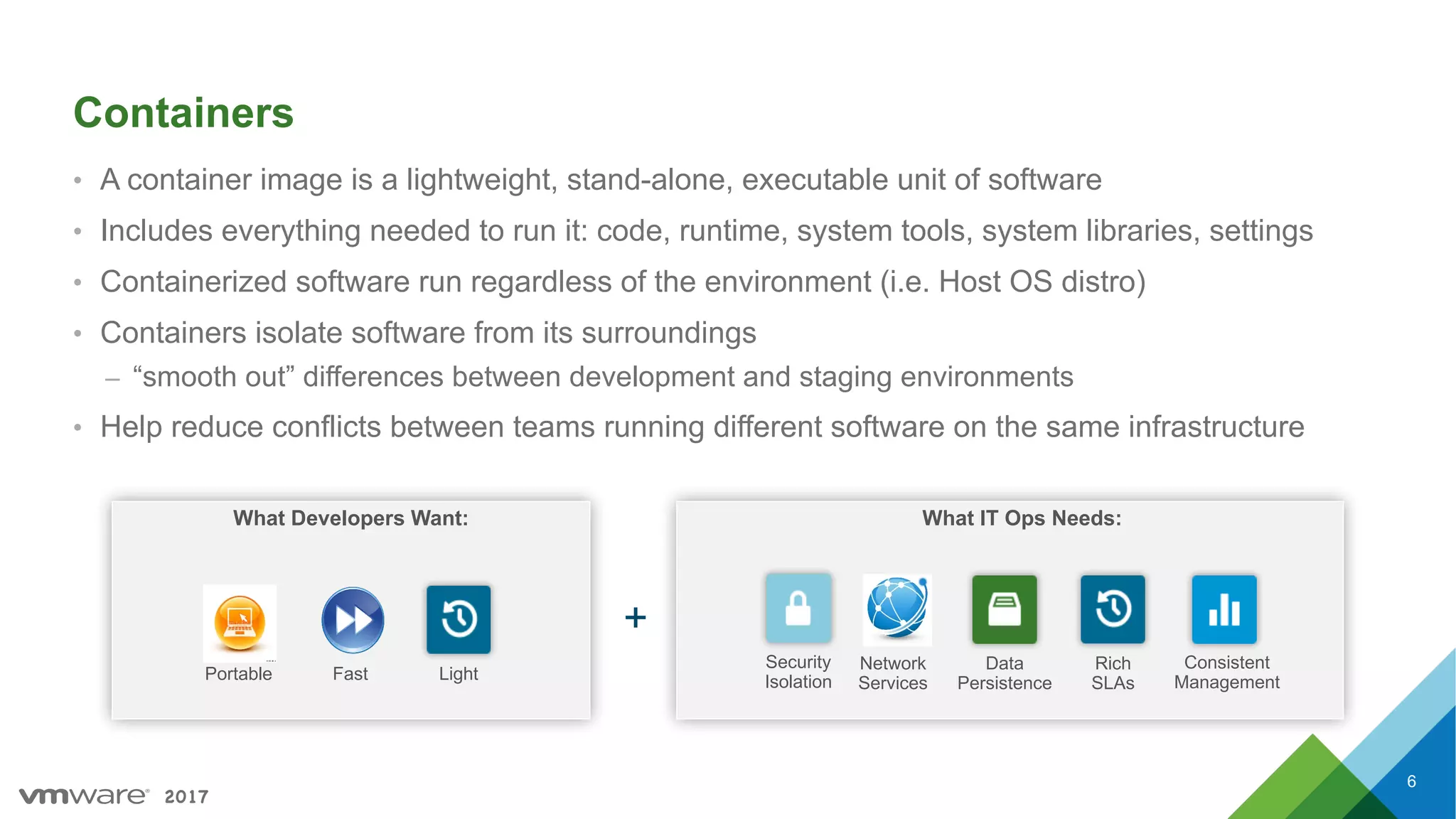
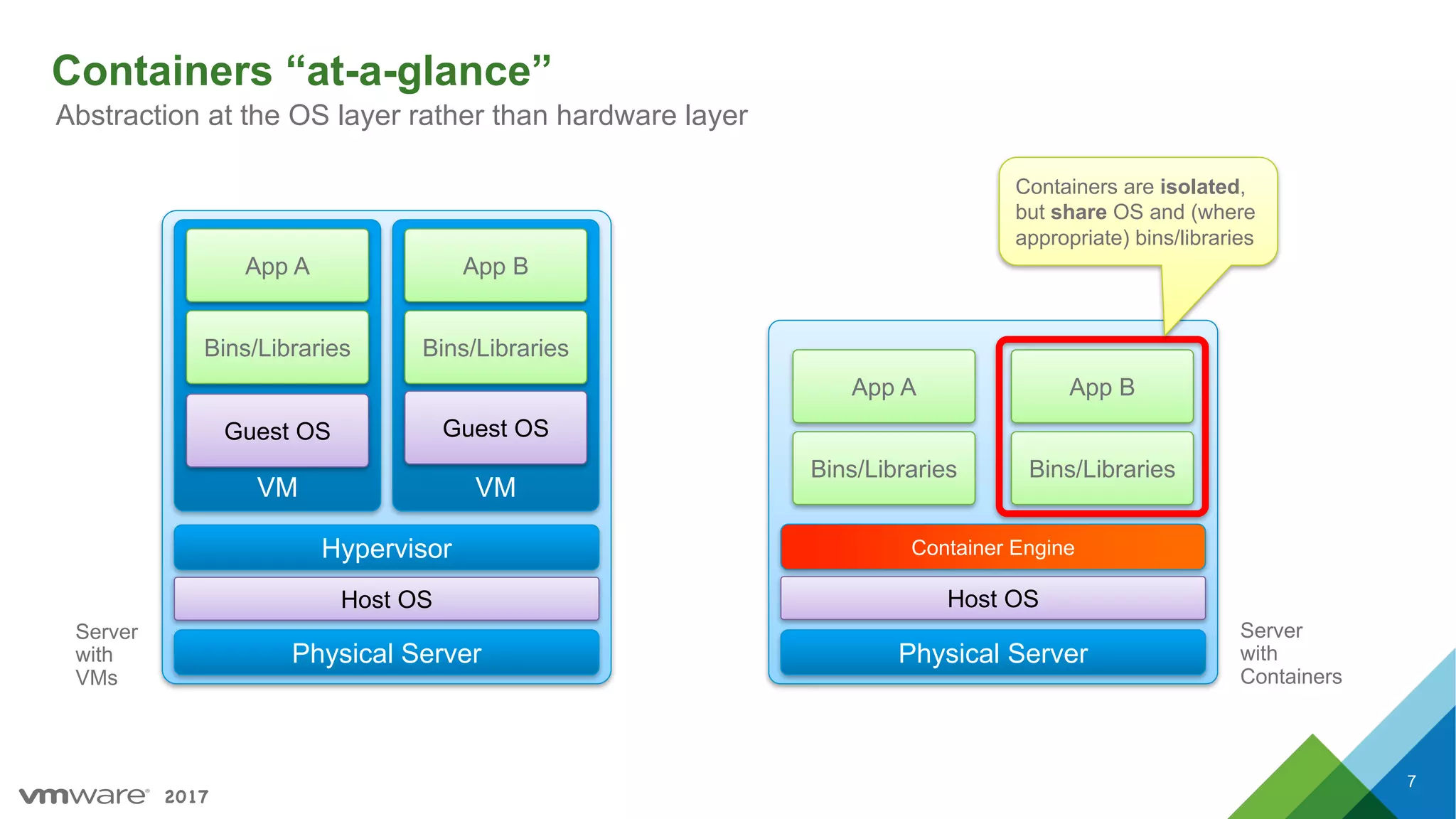
Introduction to containers and microservices, emphasizing their benefits, architecture, and the relationship between them.
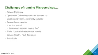
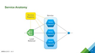
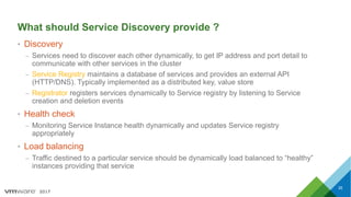
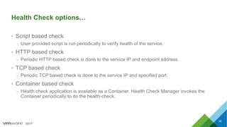
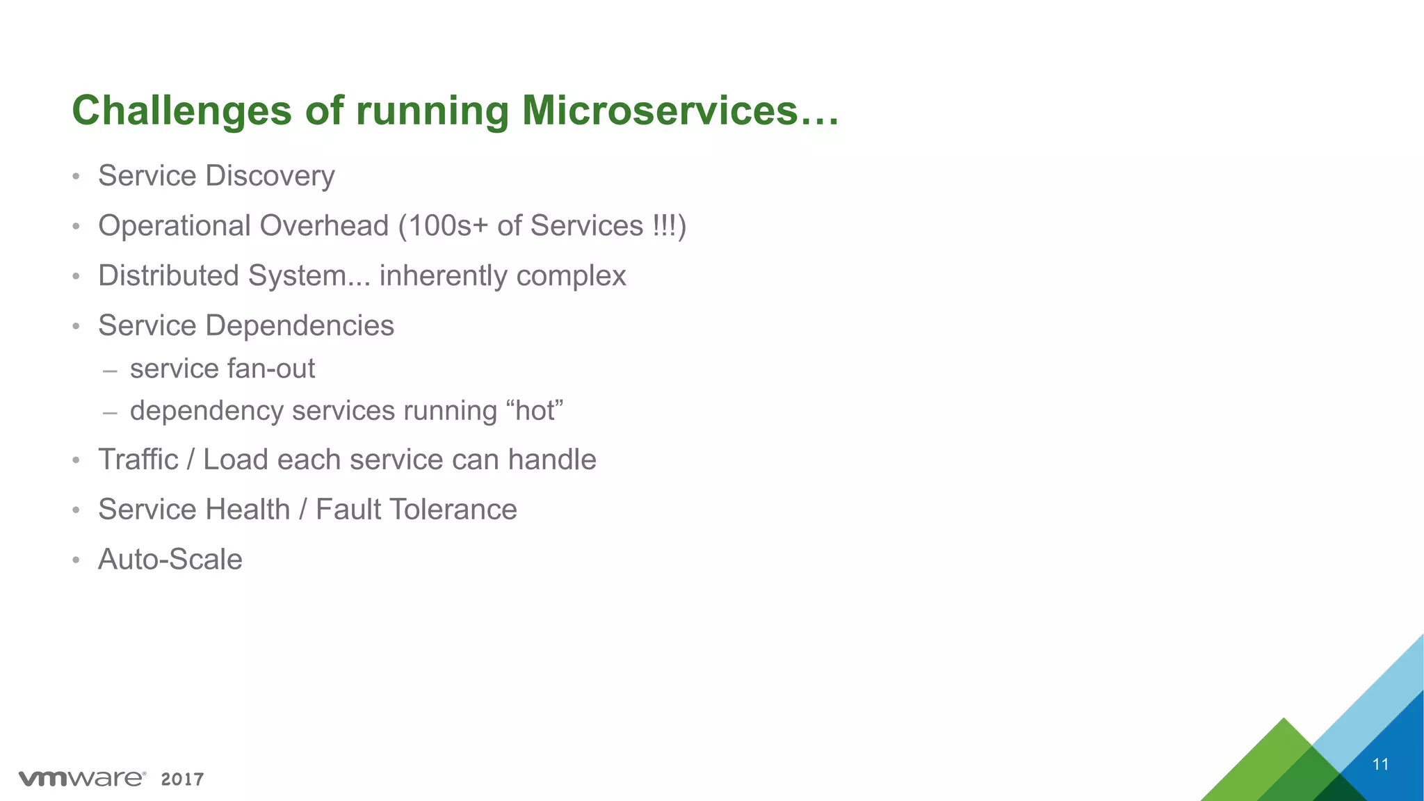
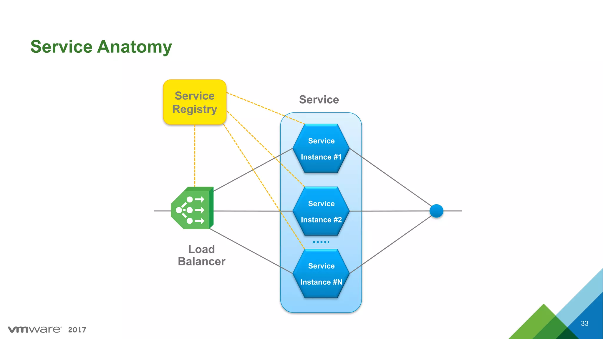
Challenges faced when running microservices, including service discovery, operational overhead, and maintaining service health.
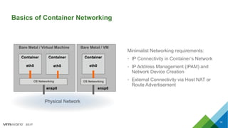
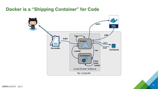
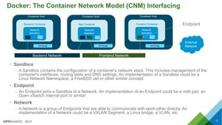
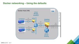
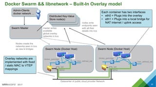
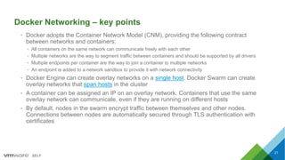
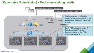
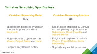
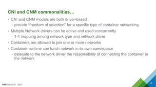
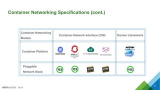
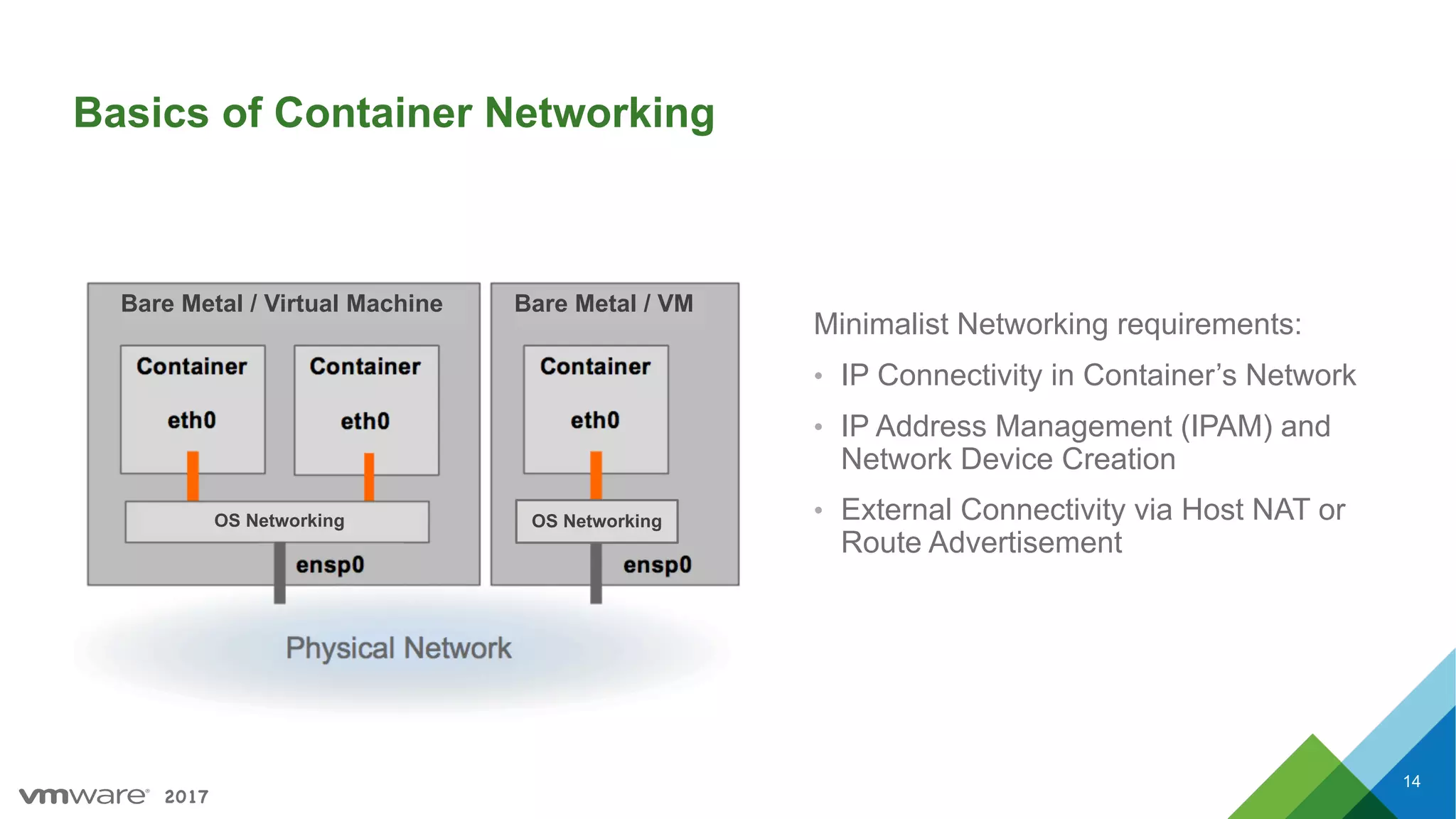
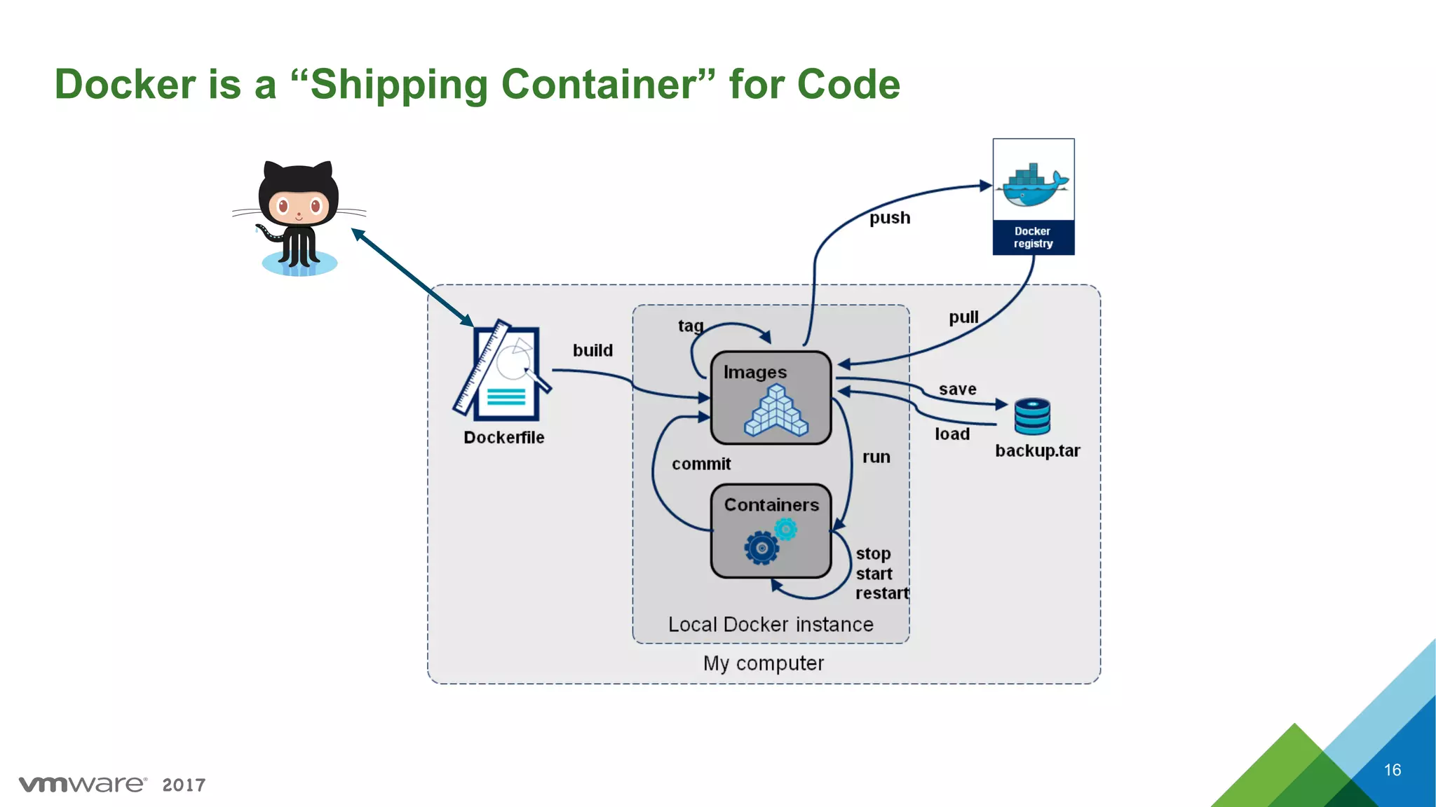
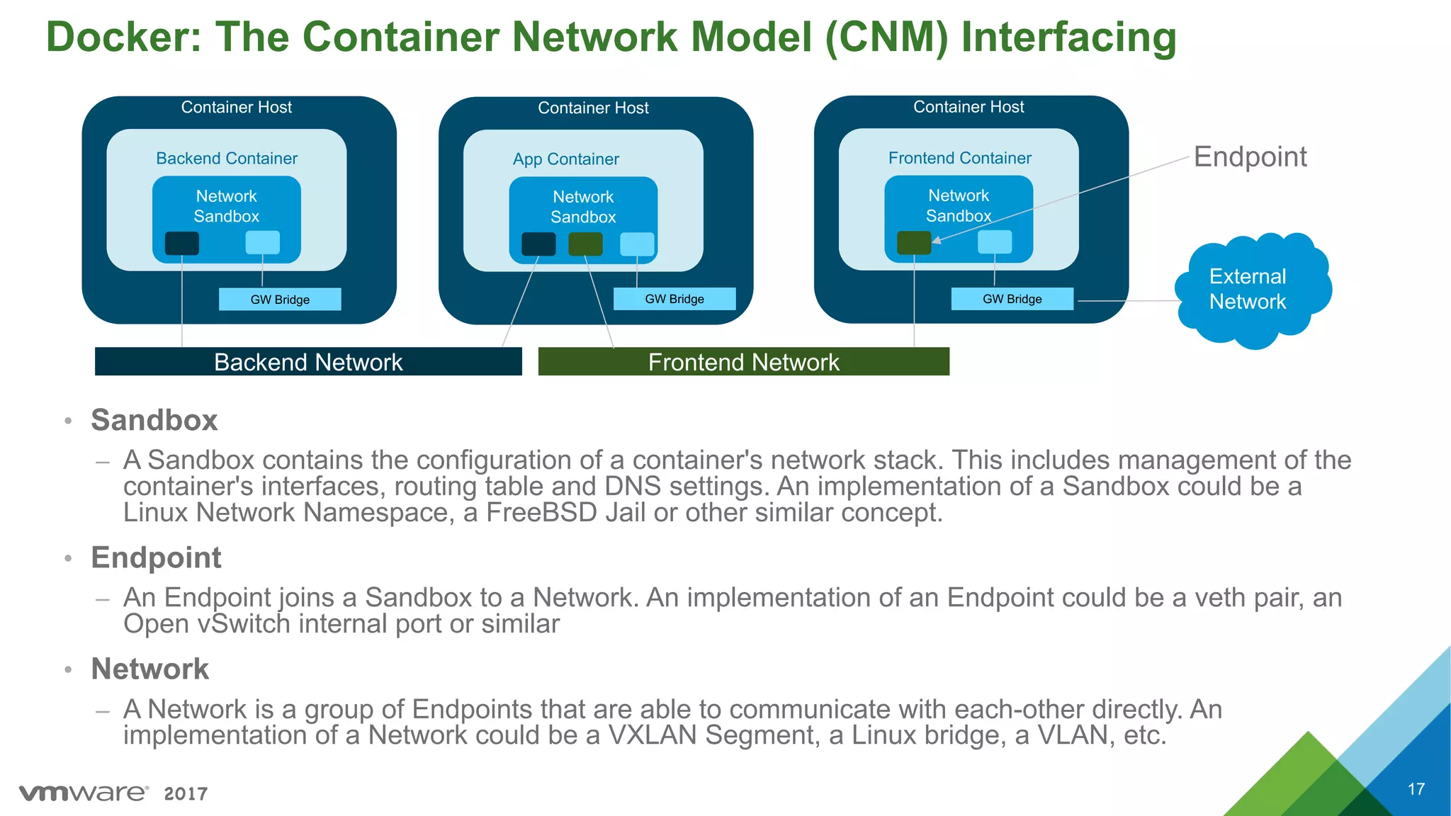
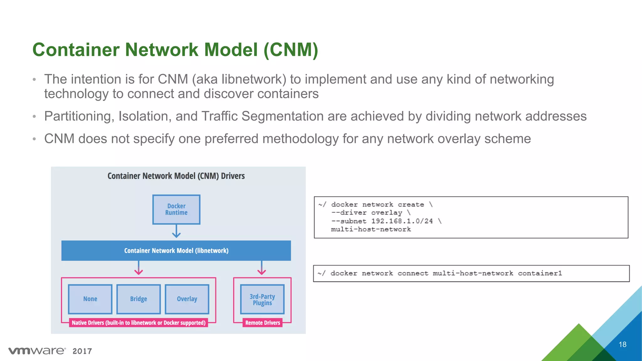
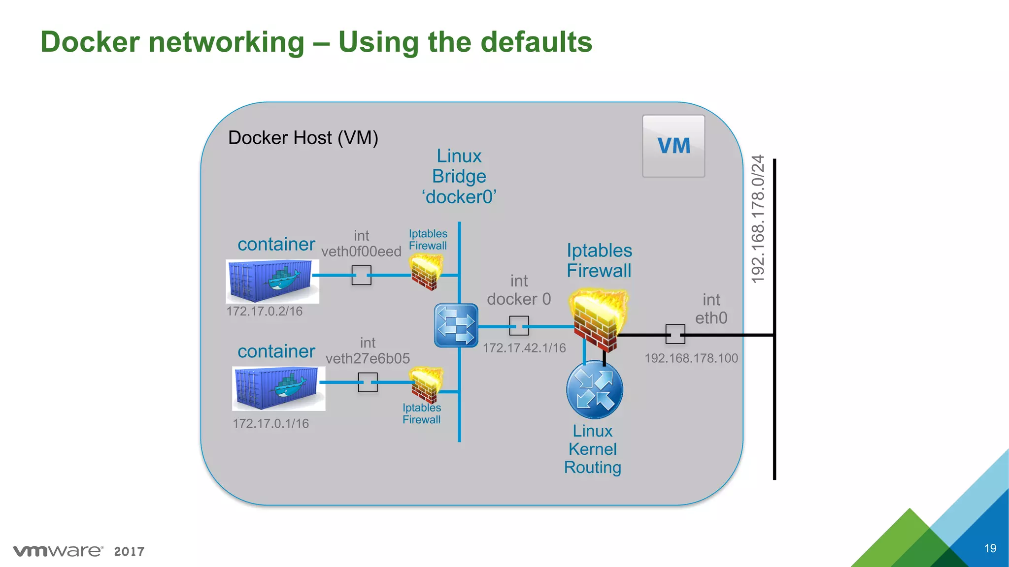
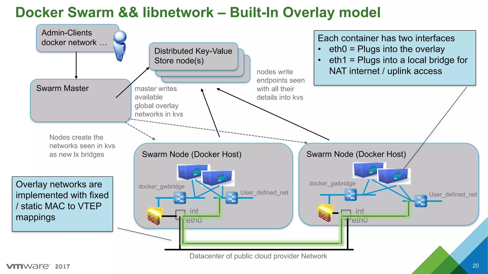
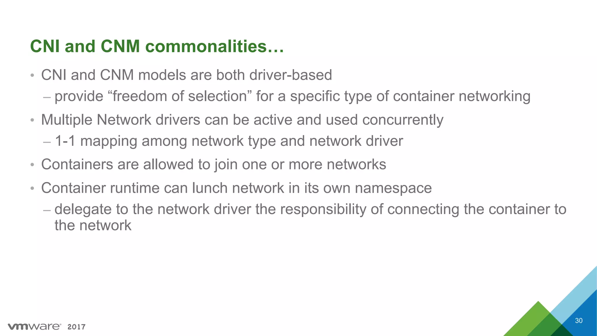
Foundations of container networking, IP connectivity requirements, and Docker's network model.
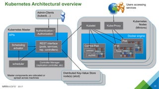
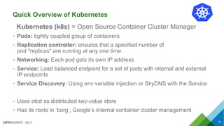
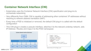
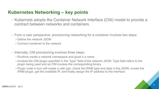
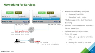
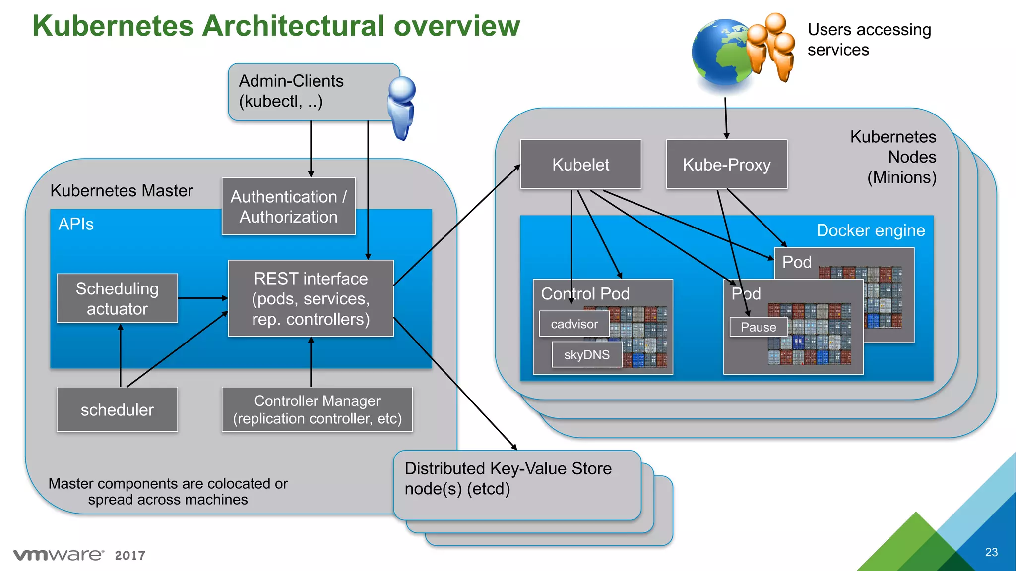
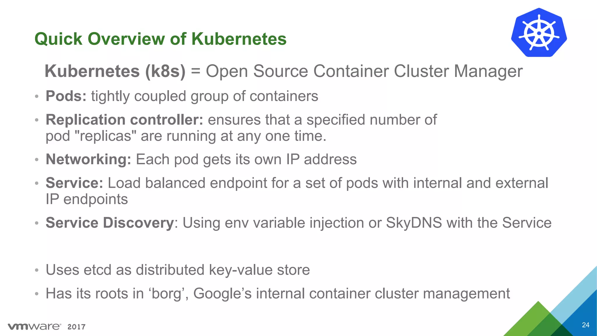
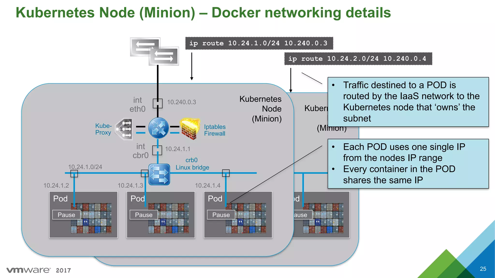
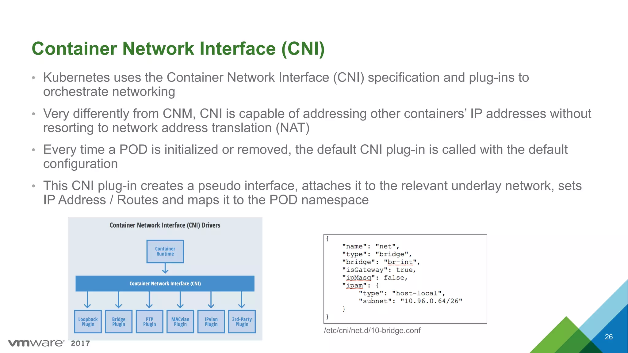
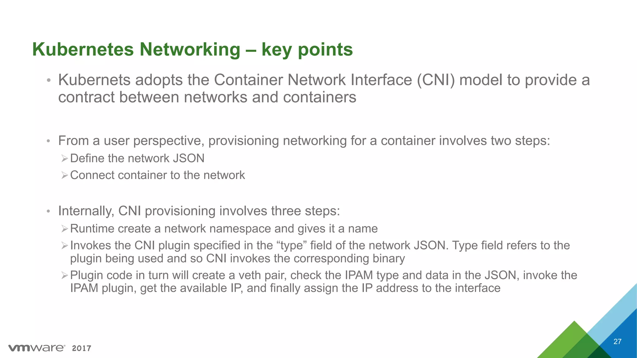
Overview of Kubernetes architecture and networking, introducing Pods, service discovery, and CNI.
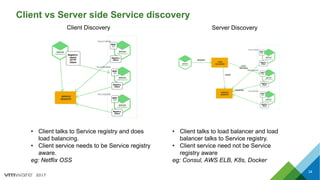
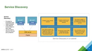
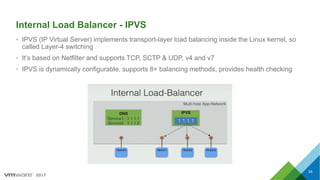
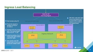
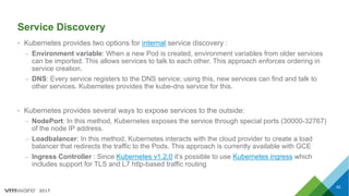
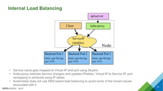
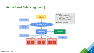
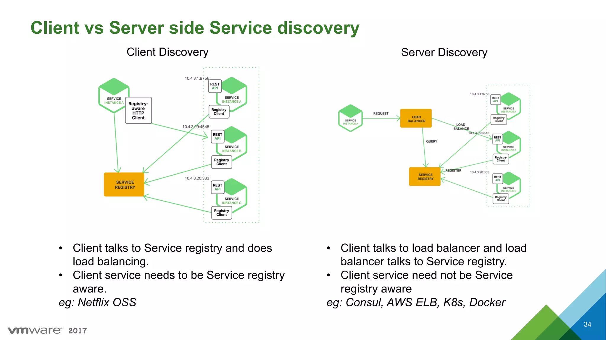
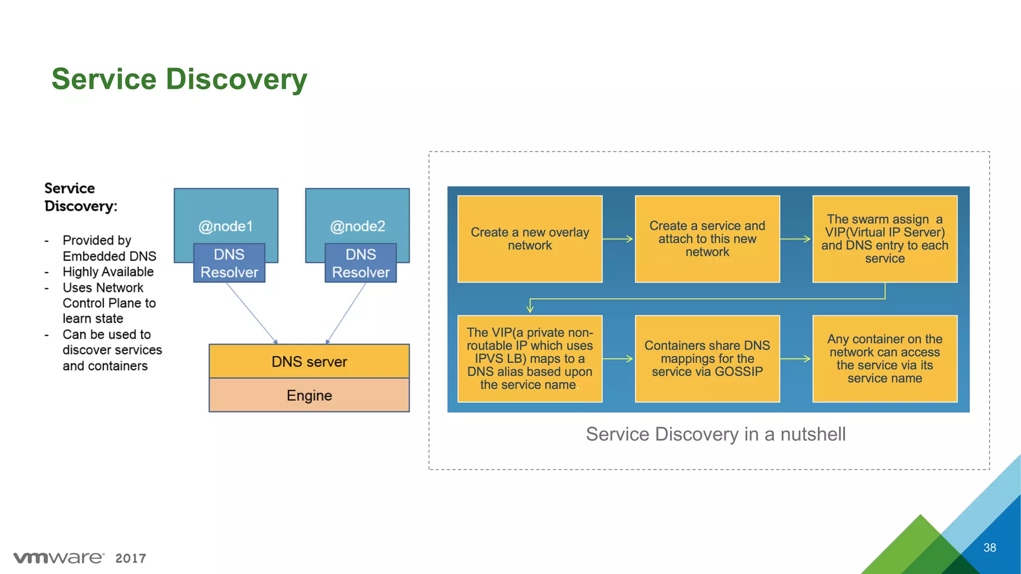
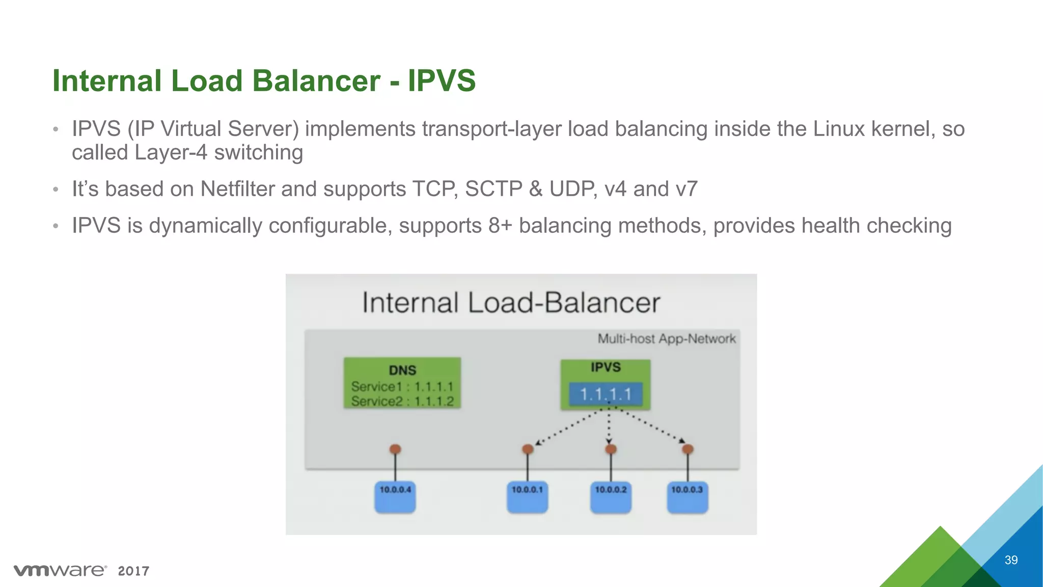
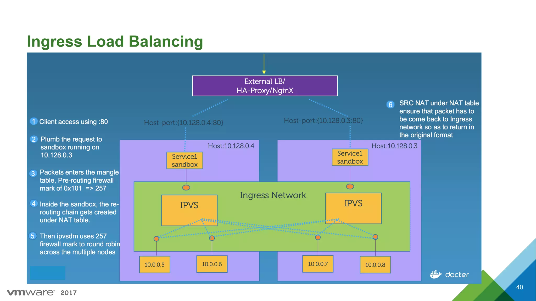
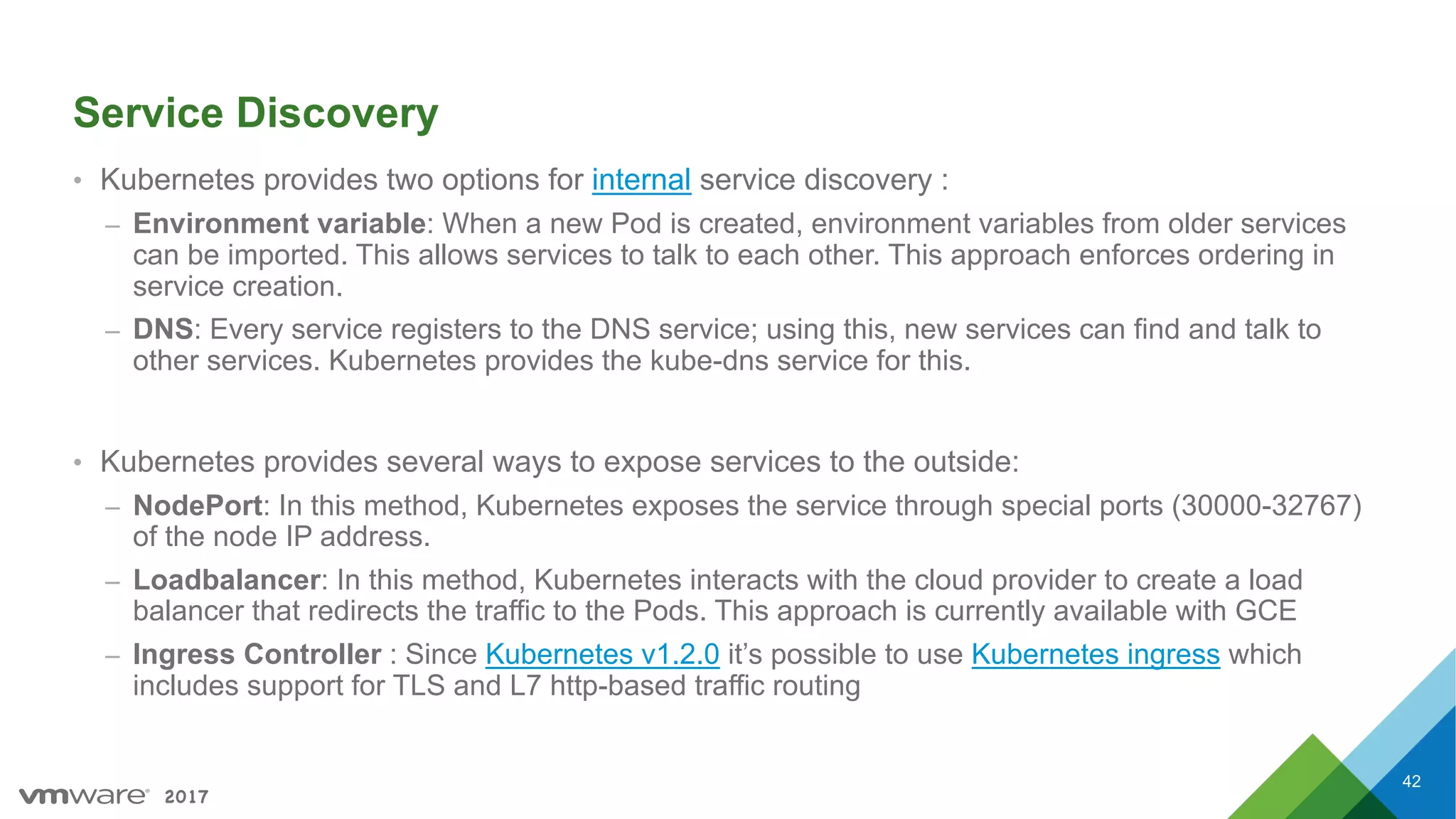
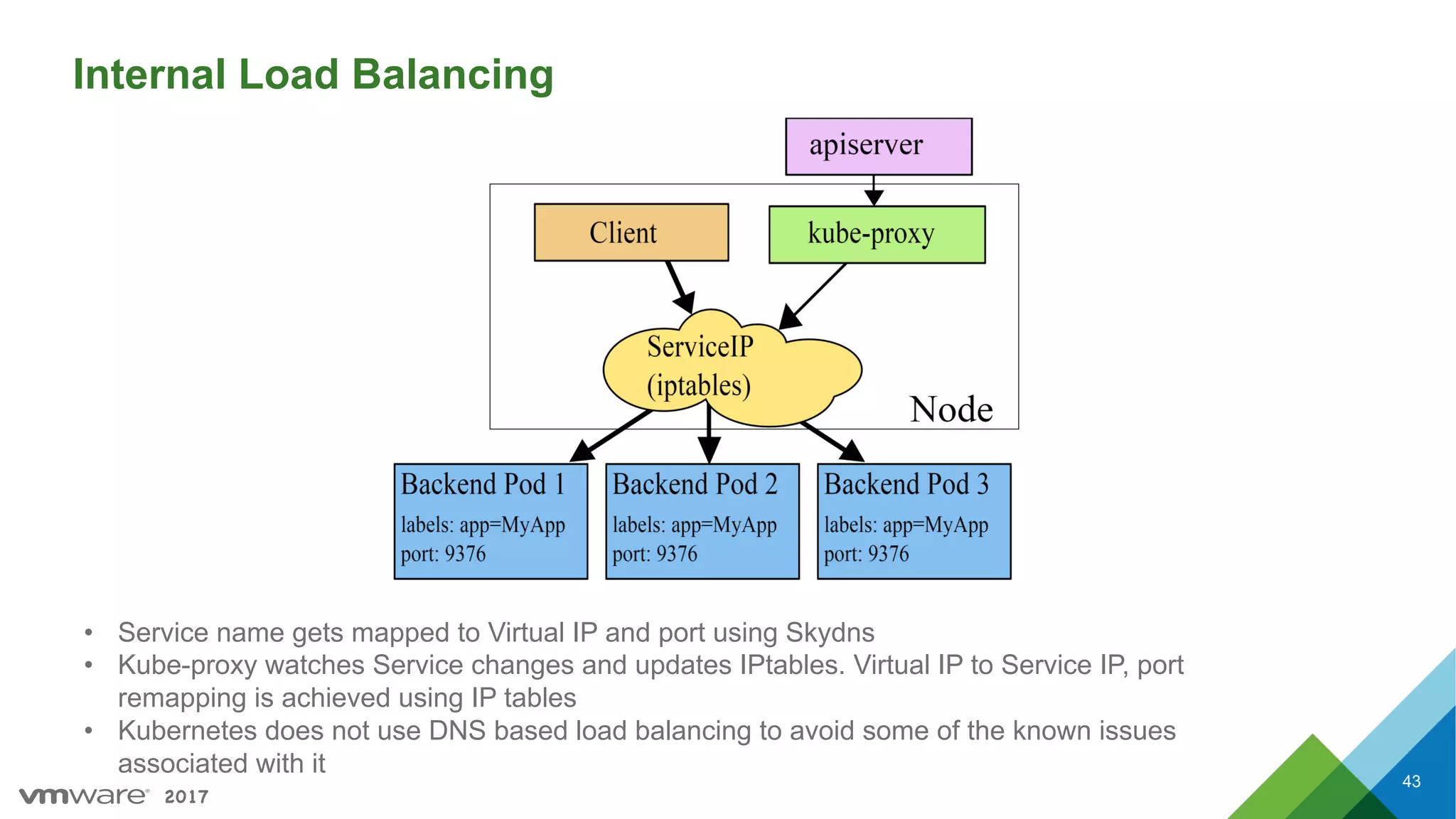
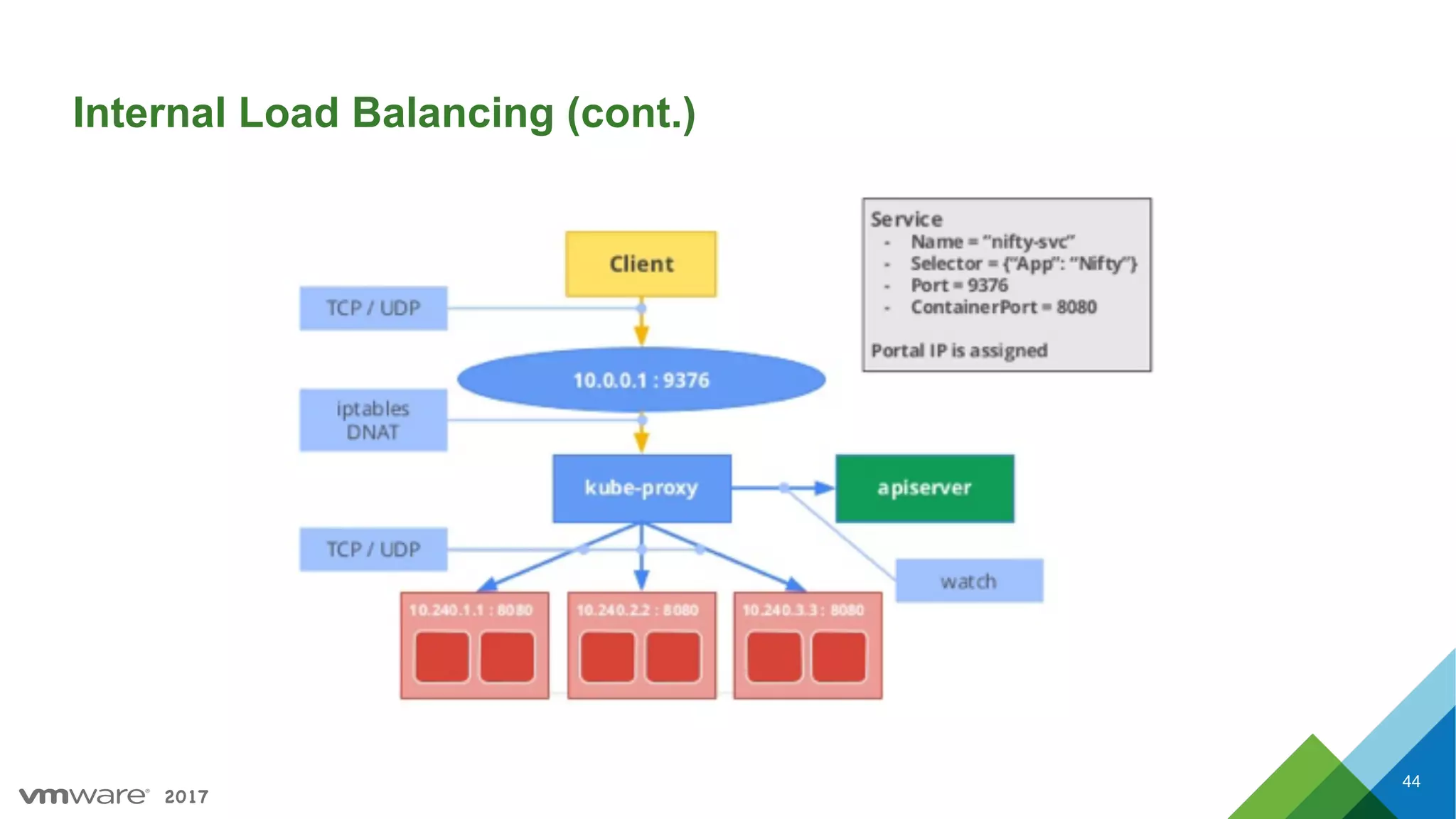
Importance of service discovery, methods of implementation in client vs. server scenarios, and Kubernetes load balancing features.
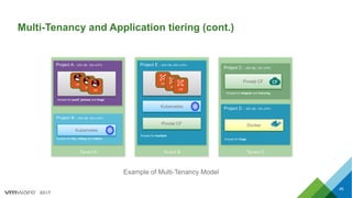
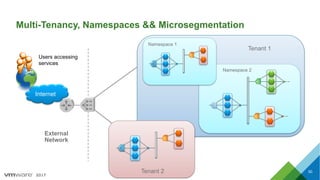
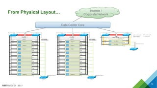
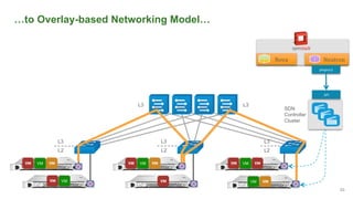
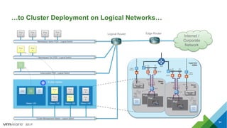
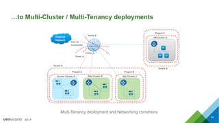
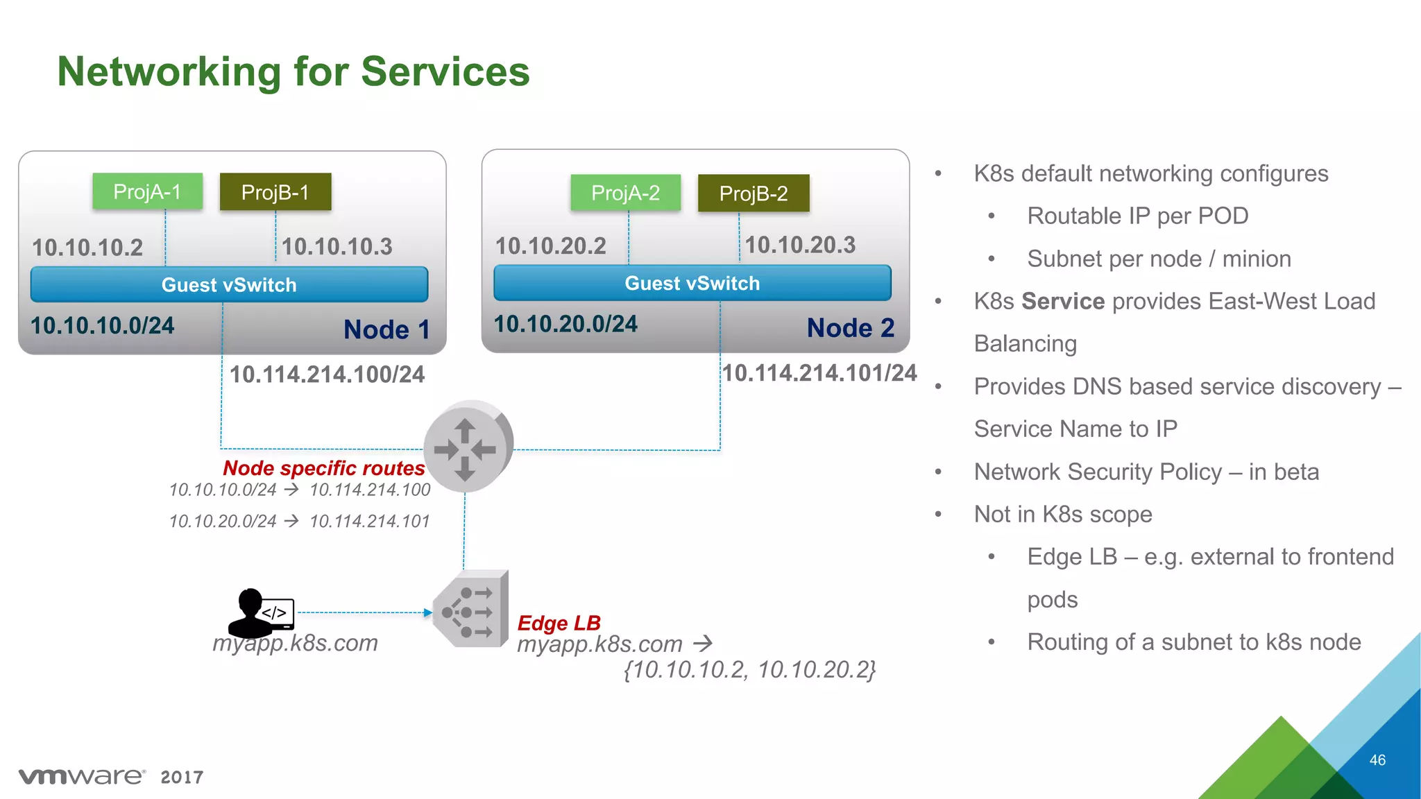
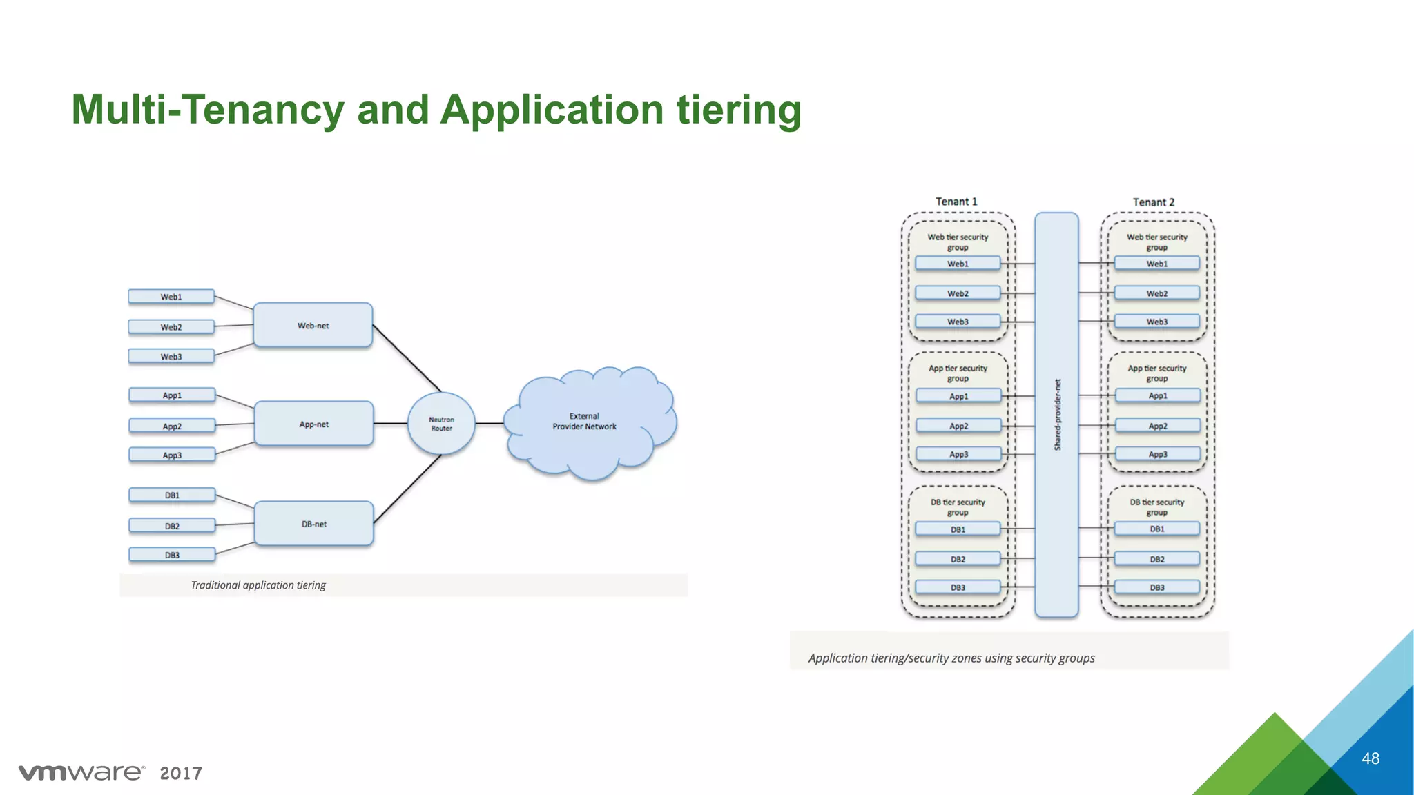
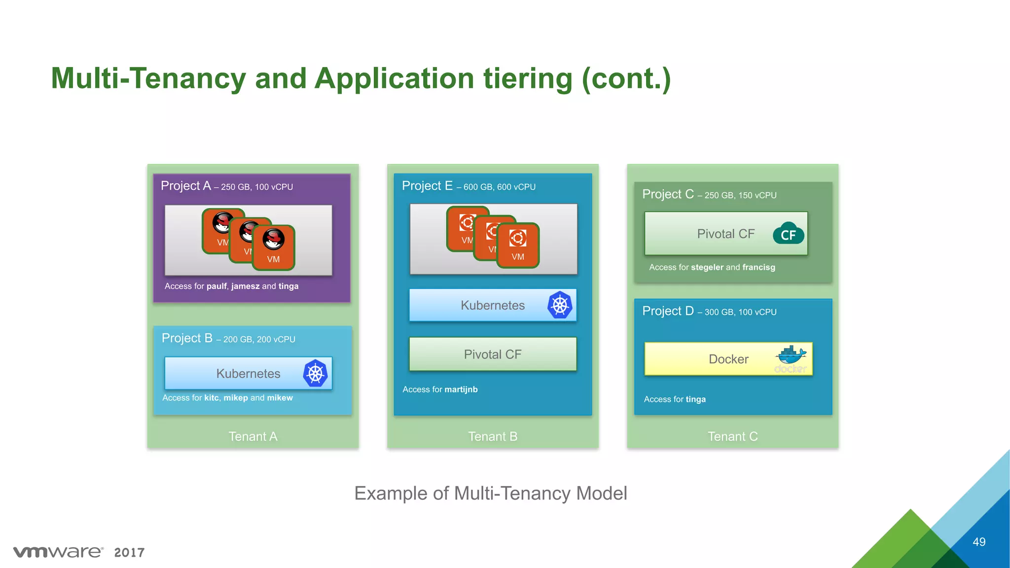
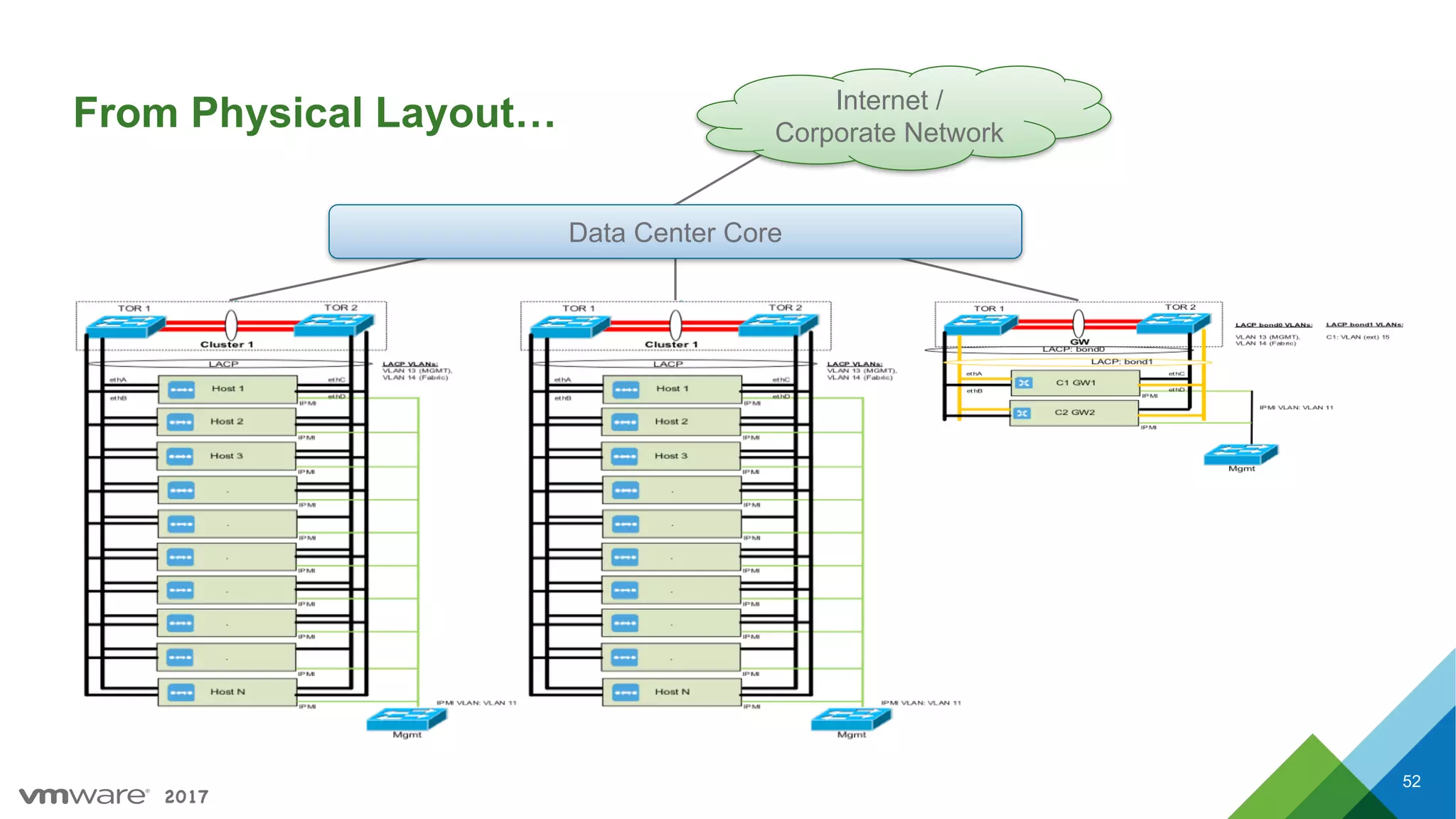
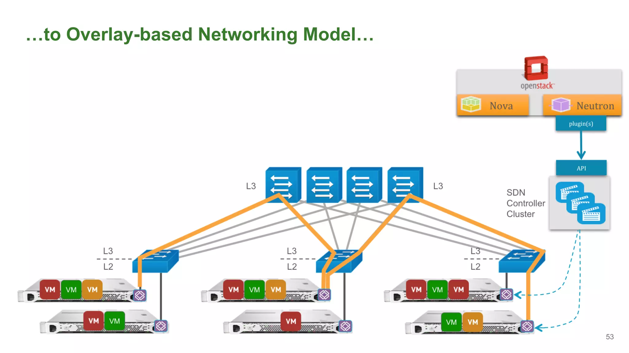
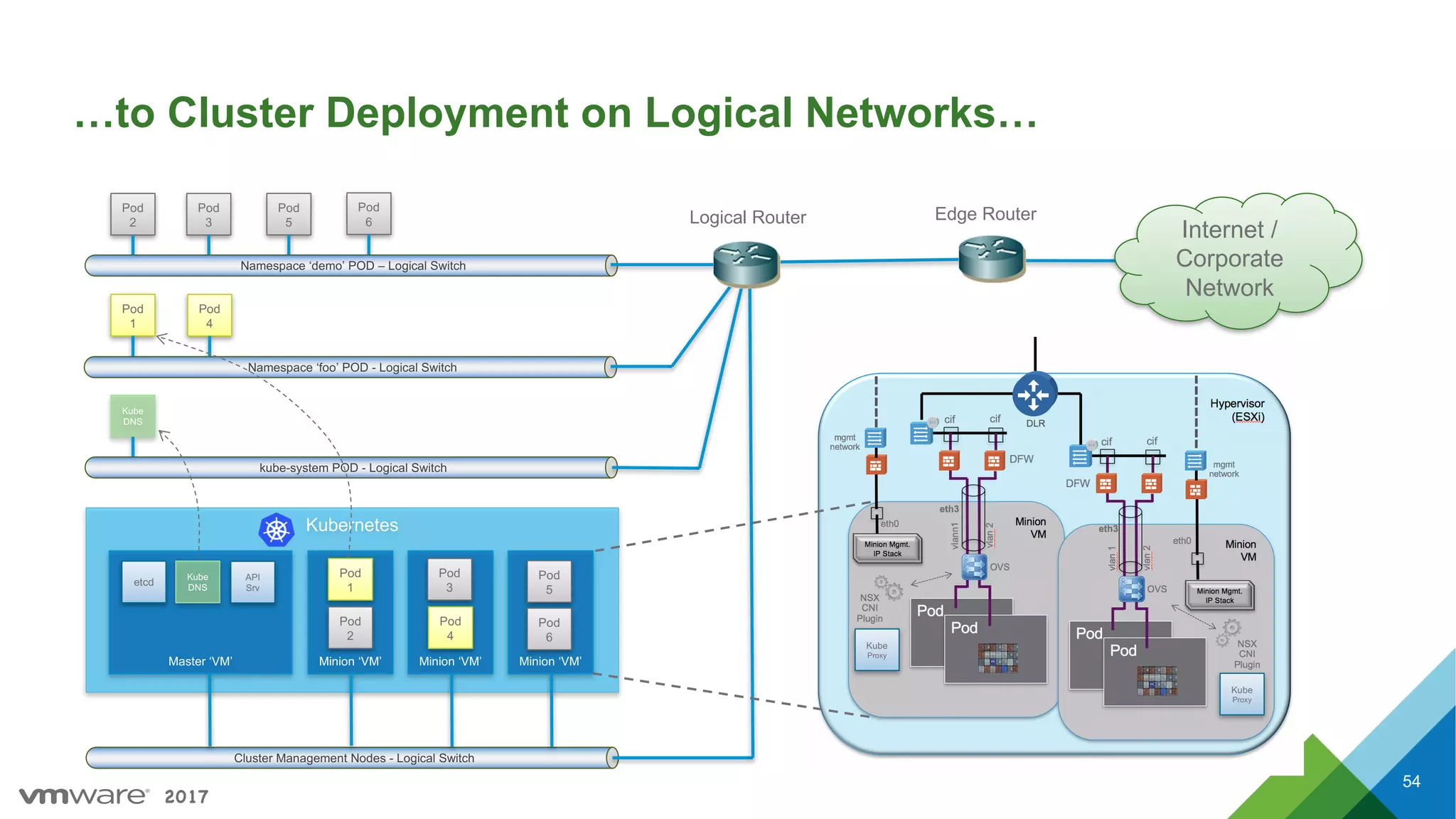
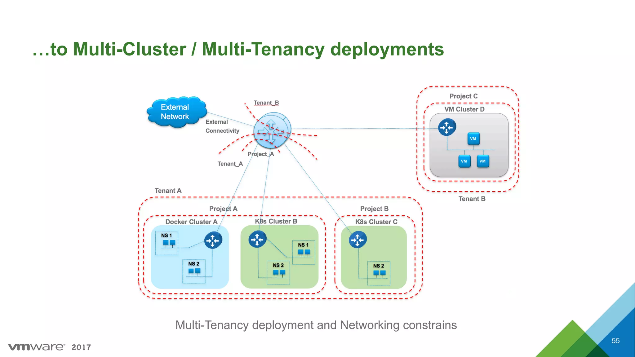
Concepts of multi-tenancy, application tiering, and the transition from physical to virtualized networking environments.
Wrap-up of the presentation and information on where to find additional resources.


![[2018] 오픈스택 5년 운영의 경험](https://cdn.slidesharecdn.com/ss_thumbnails/cloudinfra05-190131073350-thumbnail.jpg?width=600ounds&width=560&fit=bounds)


