Download to read offline


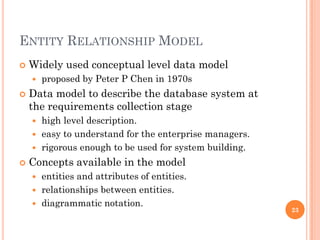


![RELATIONAL MODEL
Proposed by Edgar. F. Codd(1923-2003) in the
early seventies. [ Turing Award –1981 ]
Most of the modern DBMS are relational
Simple and elegant model with a mathematical
basis
Led to the development of a theory of data
dependencies and database design.
Relational algebra operations –
crucial role in query optimization and execution.
Laid the foundation for the development of
Tuple relational calculus and then
Database standard SQL 56](https://image.slidesharecdn.com/cs501intro-180604113050/85/Cs501-intro-56-320.jpg)


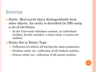
![RELATIONAL MODEL
Proposed by Edgar. F. Codd(1923-2003) in the
early seventies. [ Turing Award –1981 ]
Most of the modern DBMS are relational
Simple and elegant model with a mathematical
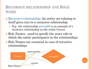
basis
Led to the development of a theory of data
dependencies and database design.
Relational algebra operations –
crucial role in query optimization and execution.
Laid the foundation for the development of
Tuple relational calculus and then
Database standard SQL 56](https://image.slidesharecdn.com/cs501intro-180604113050/75/Cs501-intro-56-2048.jpg)

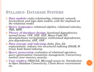
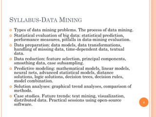
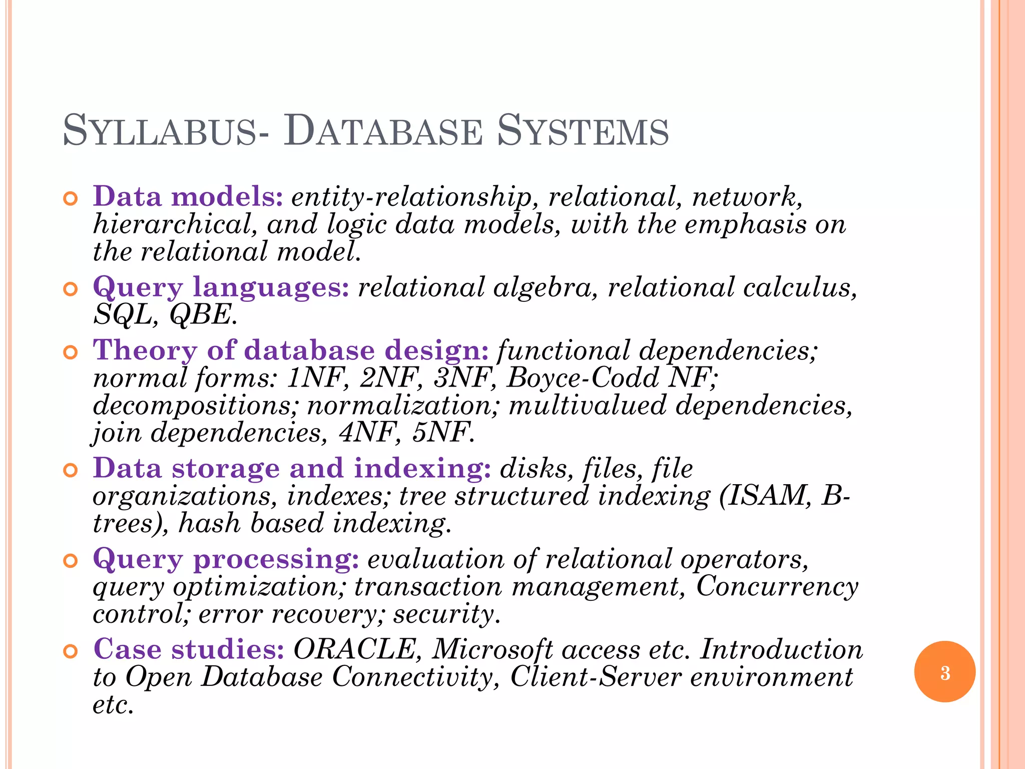
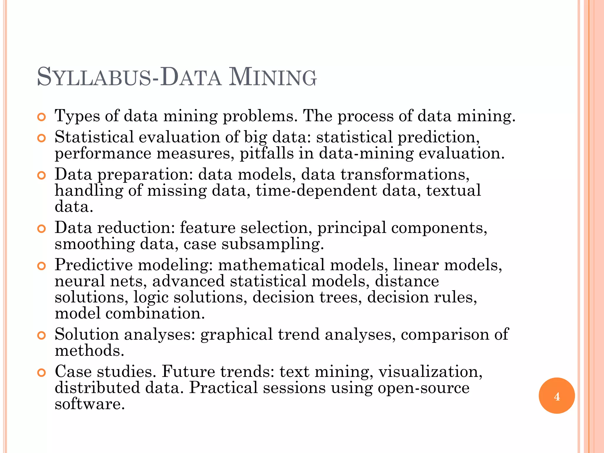
This document provides information about the CS501 Database Systems and Data Mining course. It includes details about the course structure, timings, syllabus, evaluation policy, and introductory concepts about databases and database management systems. The syllabus covers topics such as data models, query languages, database design, data storage and indexing, query processing, and data mining concepts and techniques. Required textbooks and the evaluation criteria consisting of assignments, quizzes, mid-semester and end-semester exams are also specified.


