Downloaded 113 times


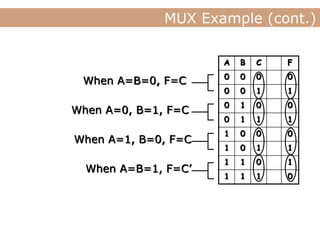

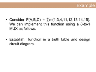
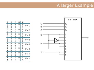
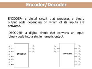
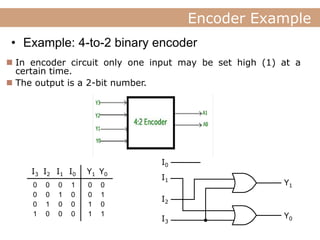
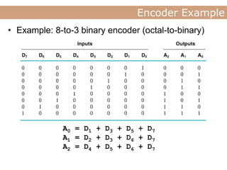
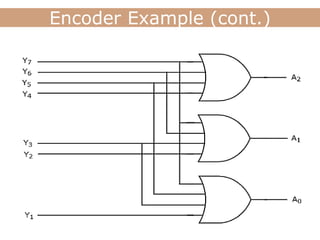
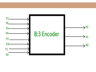
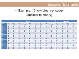
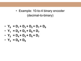
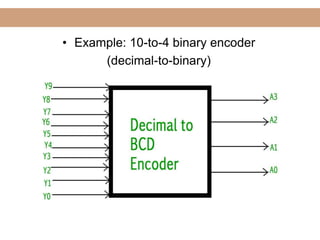
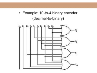
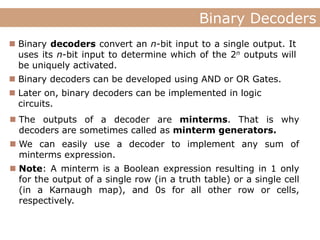
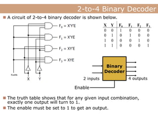
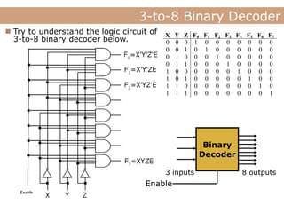
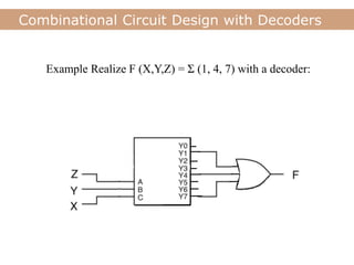
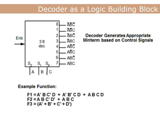
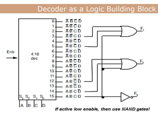

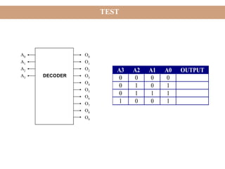
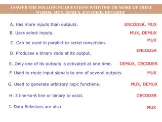


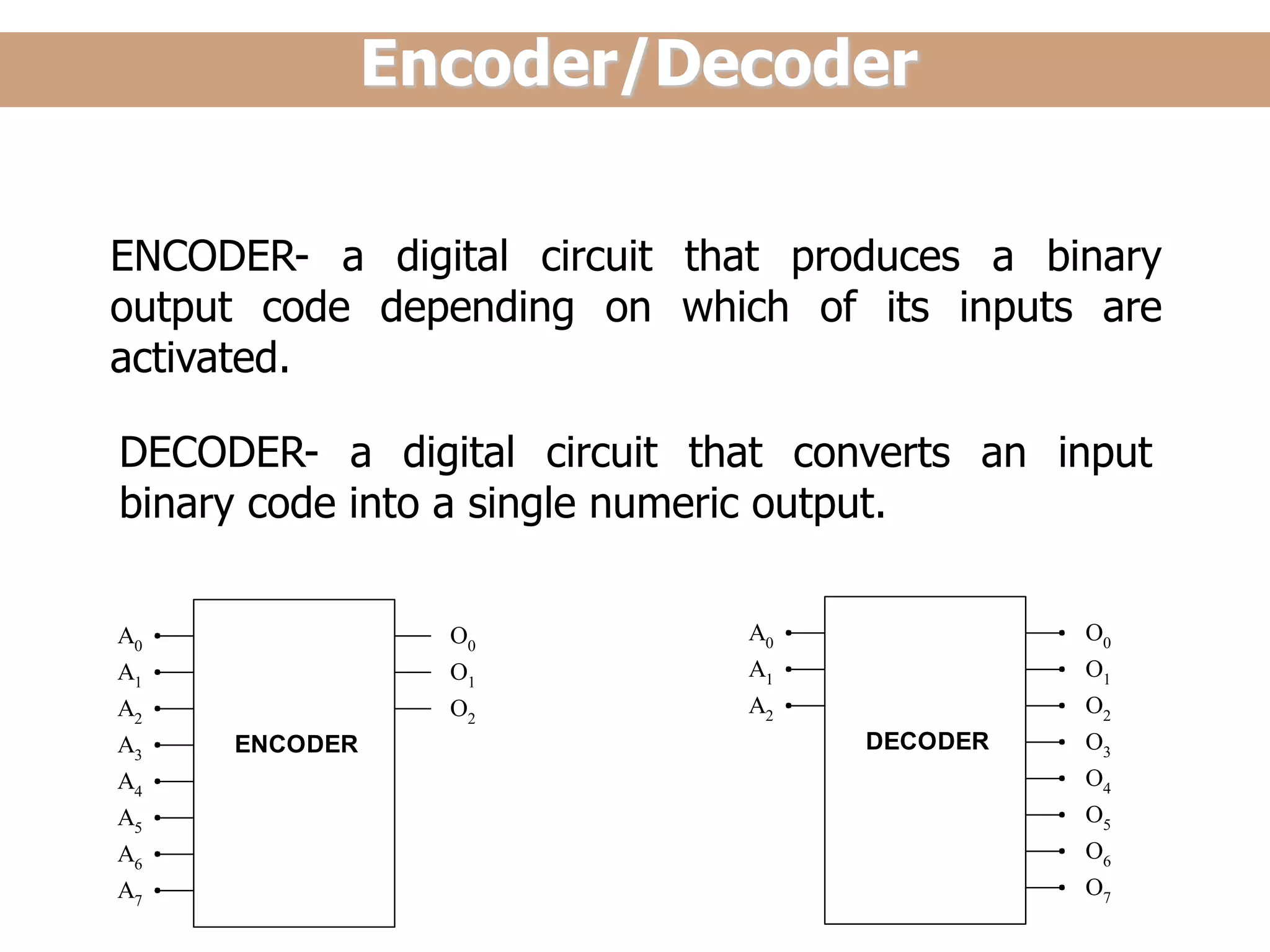
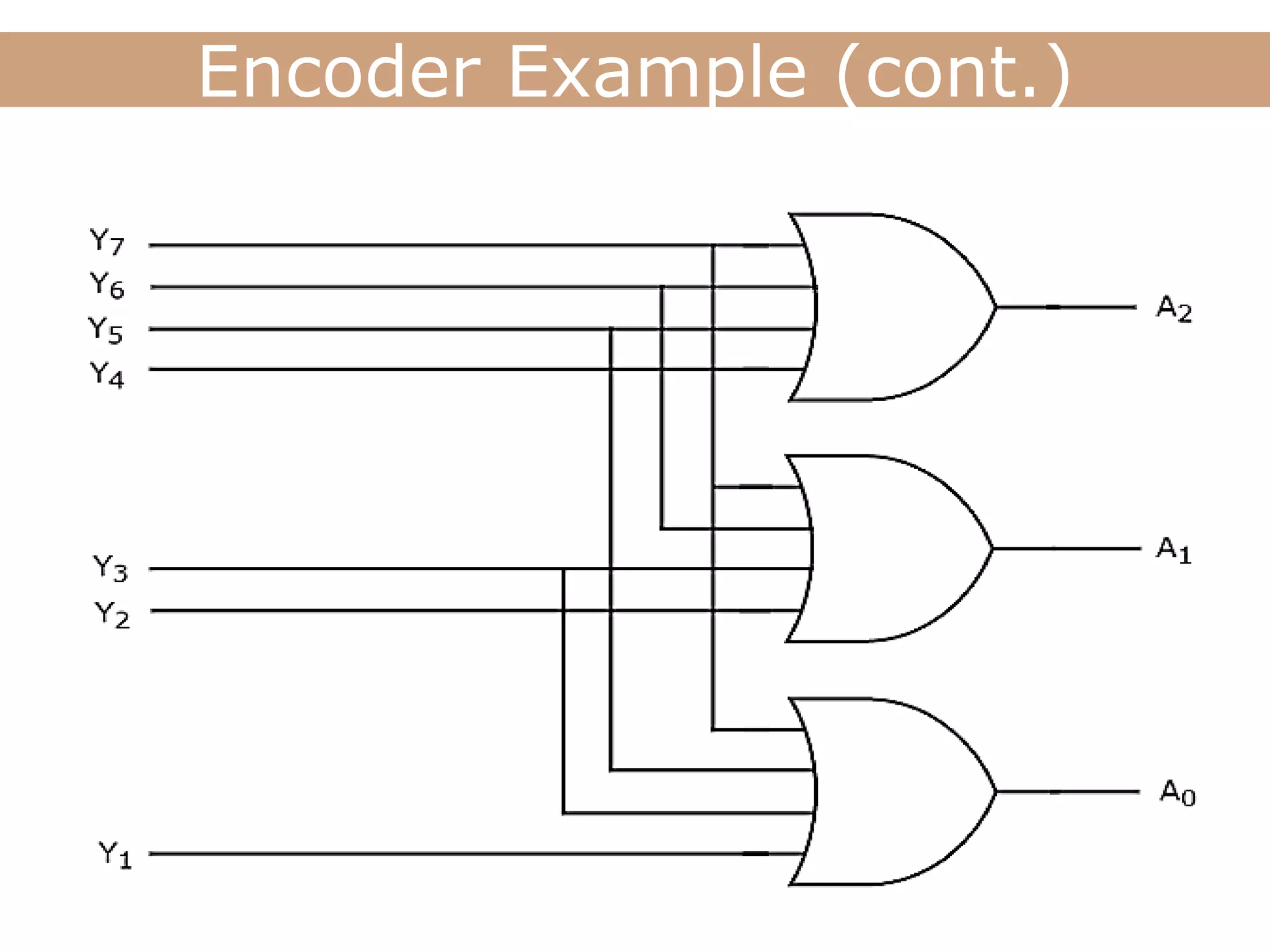
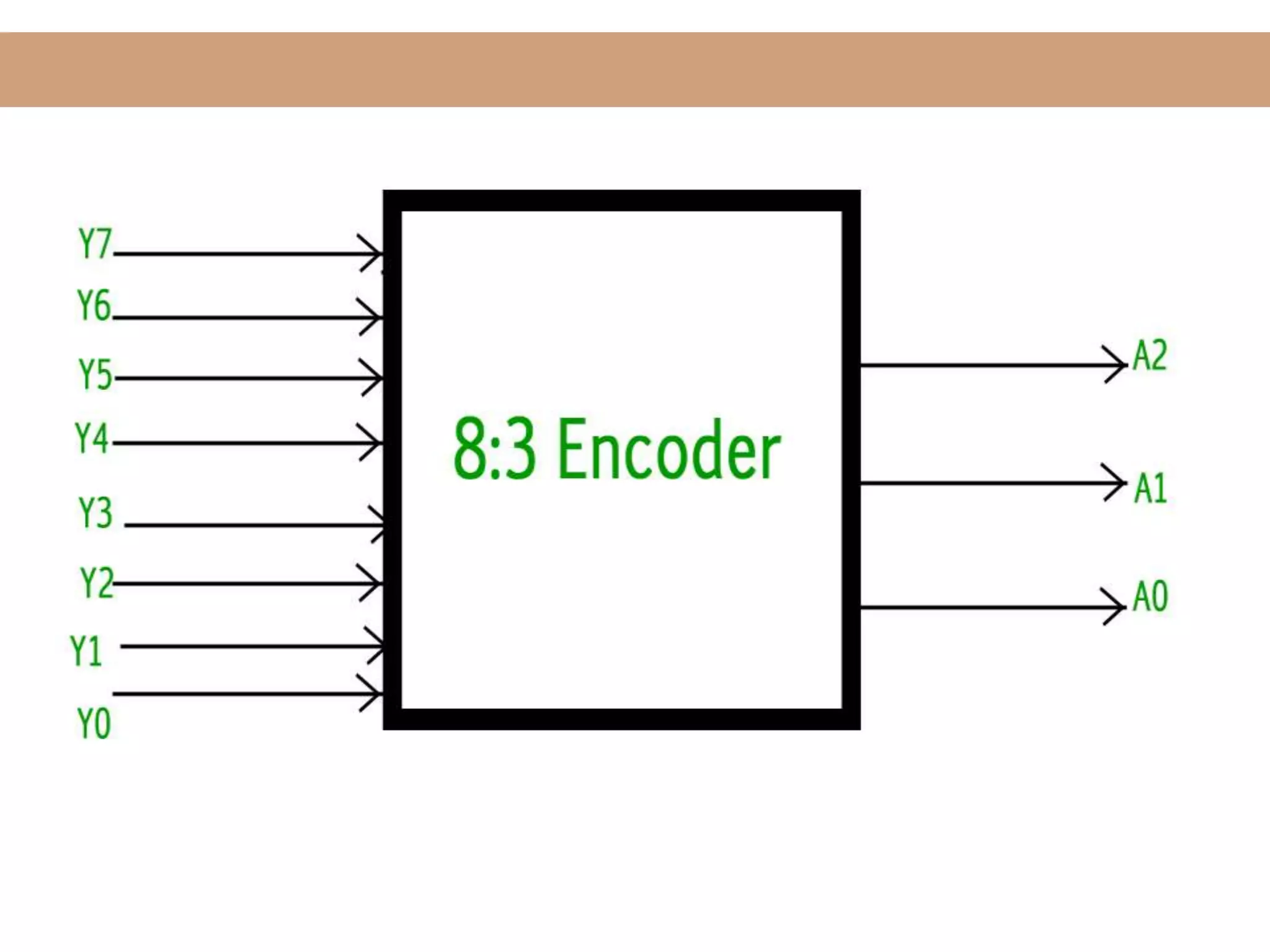
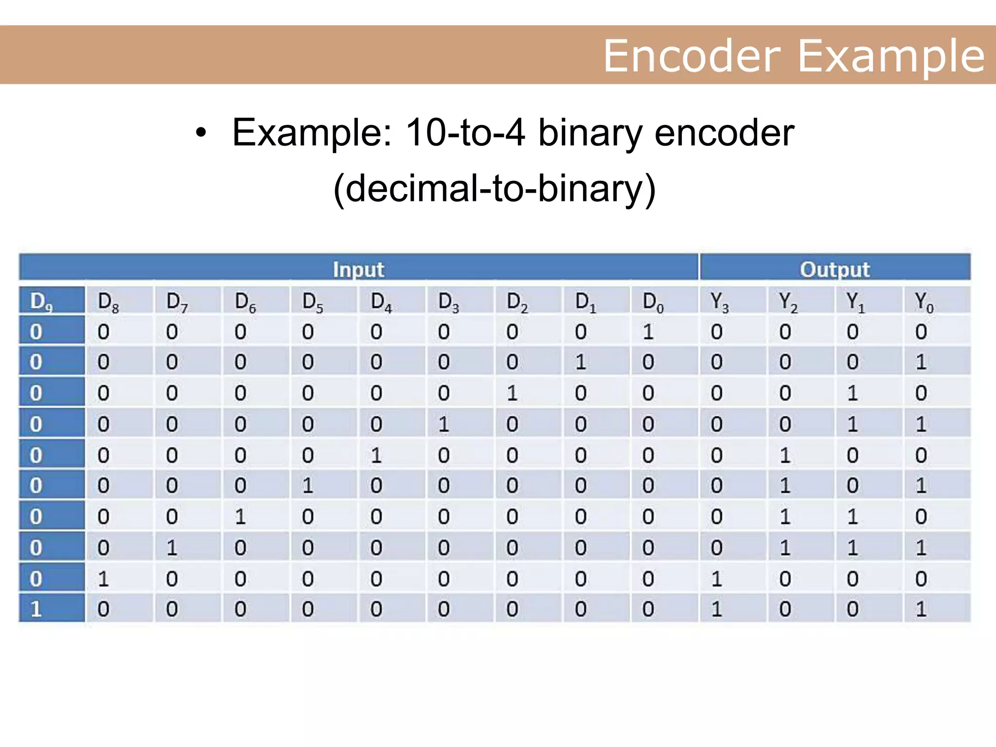
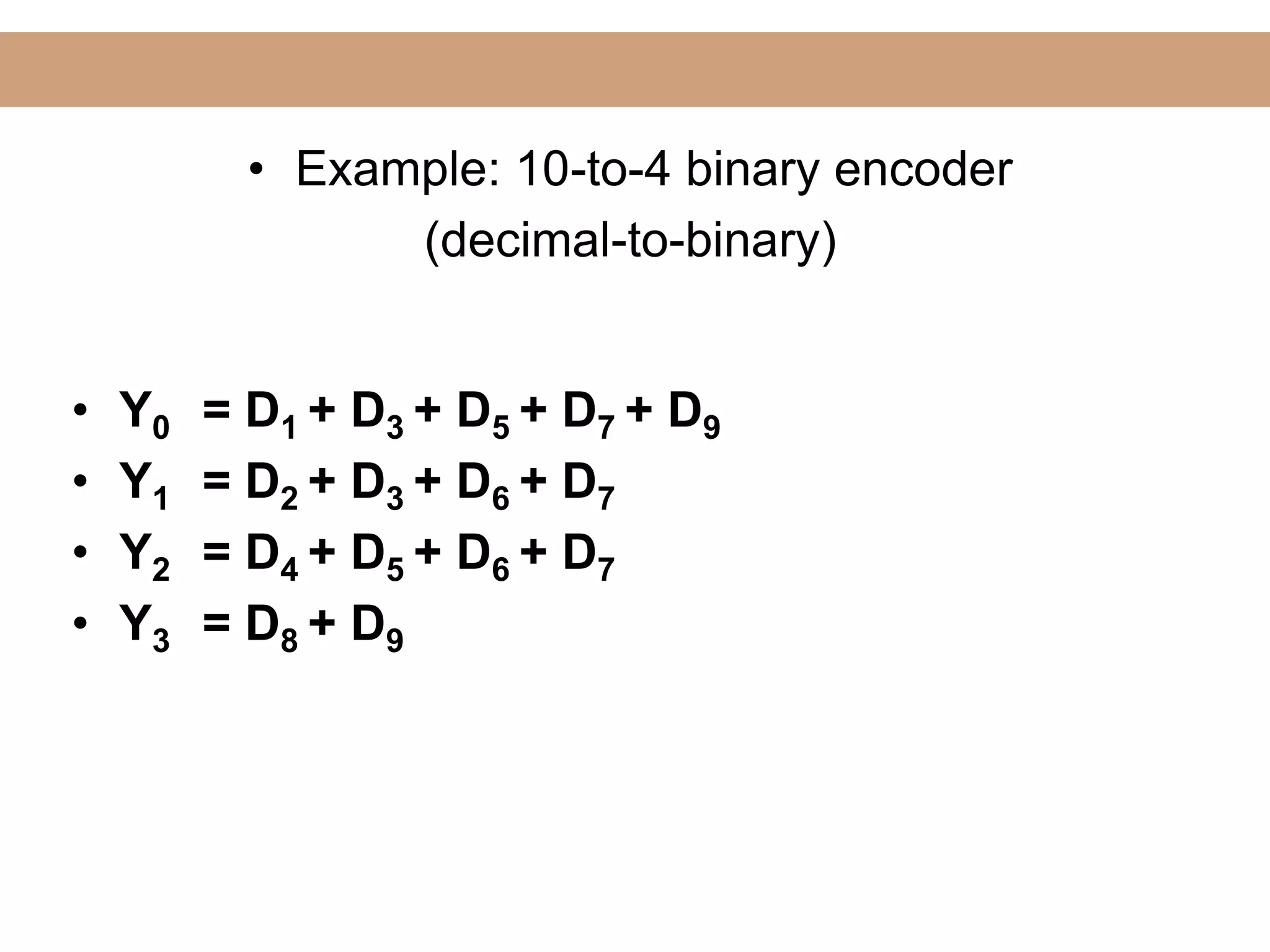
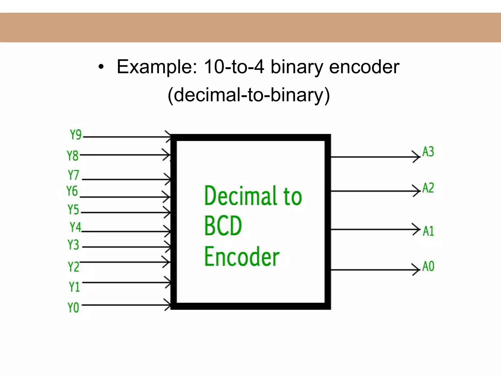
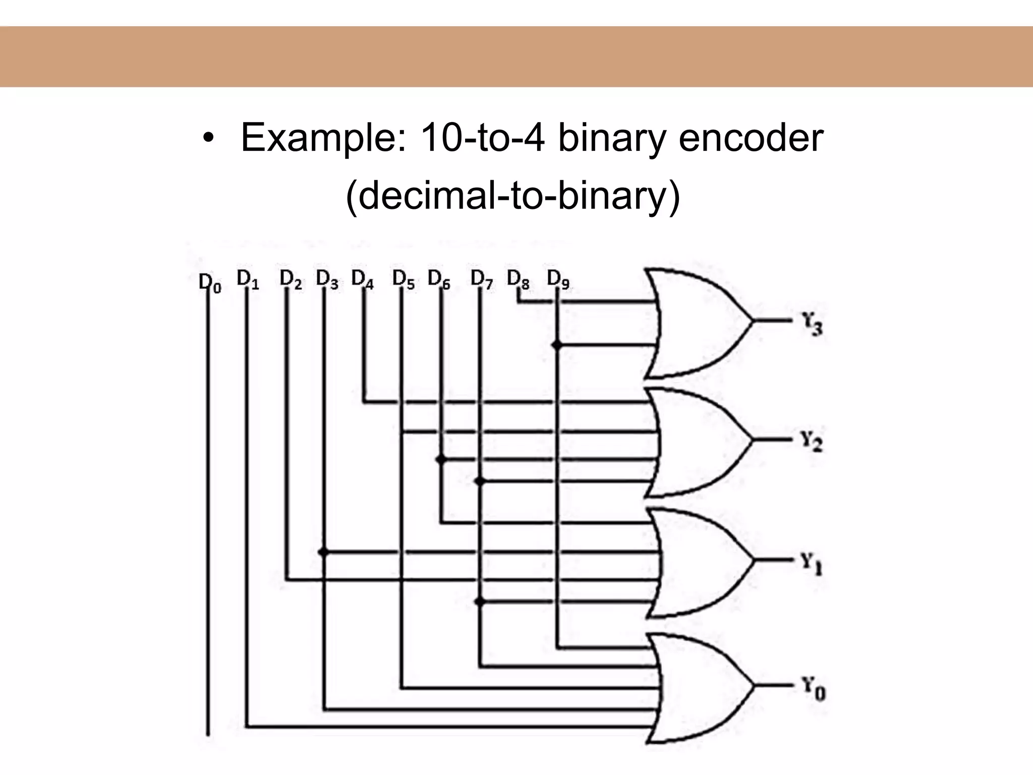
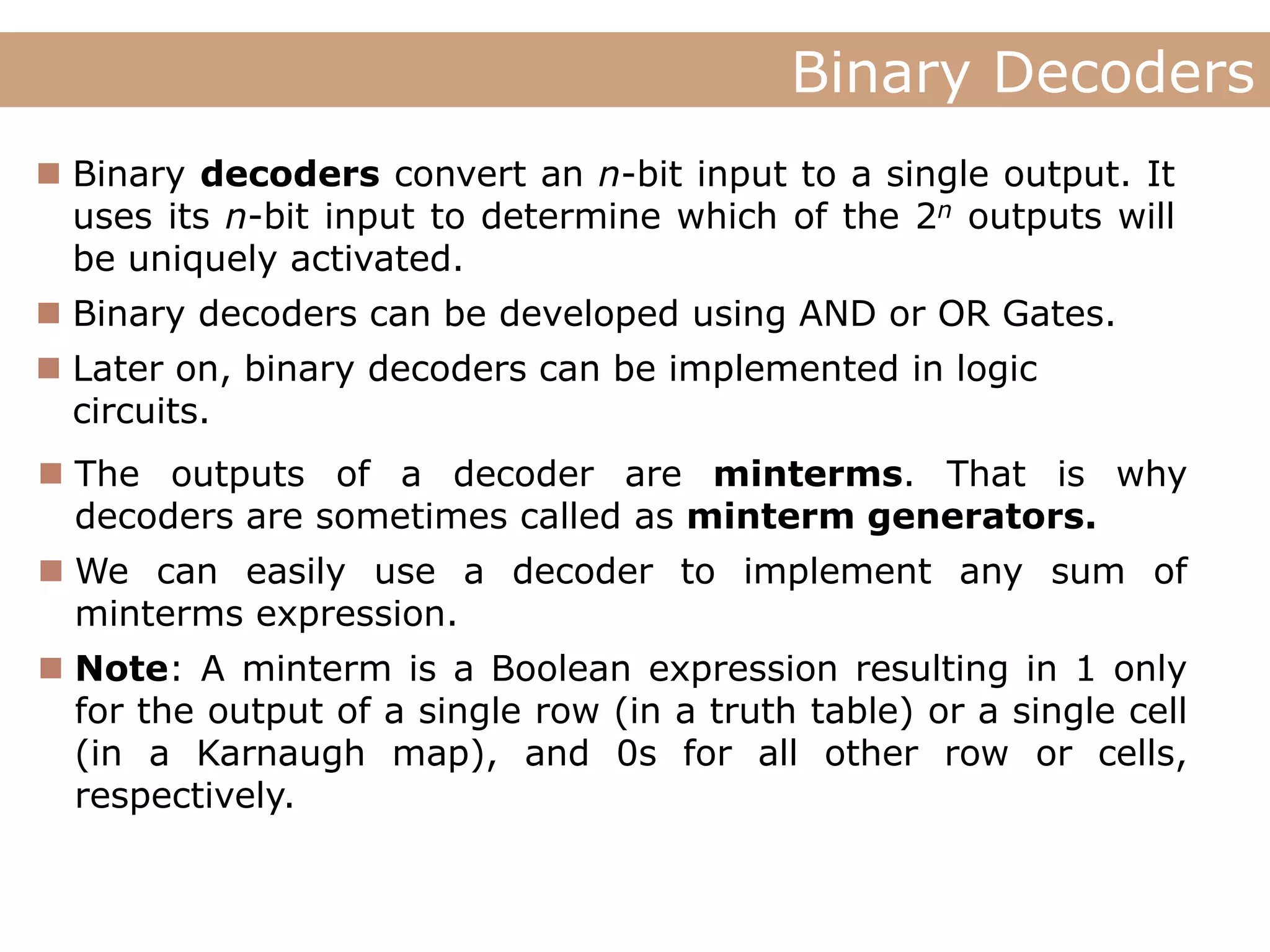
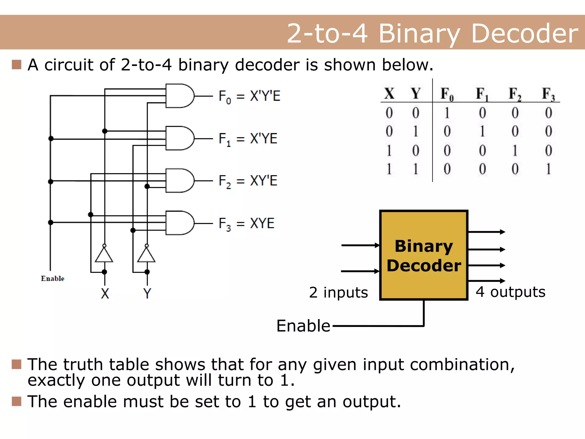

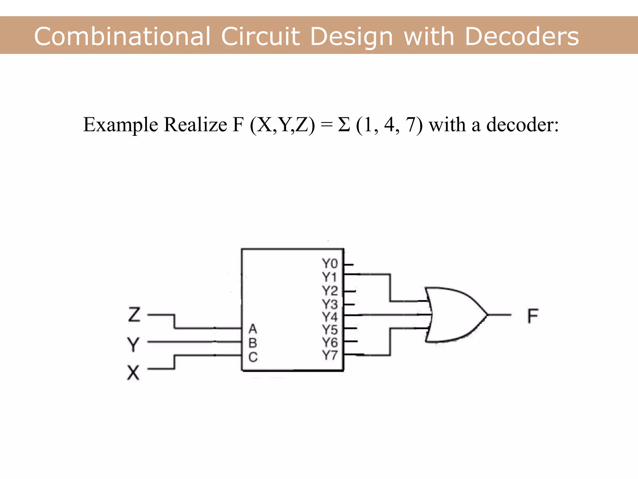

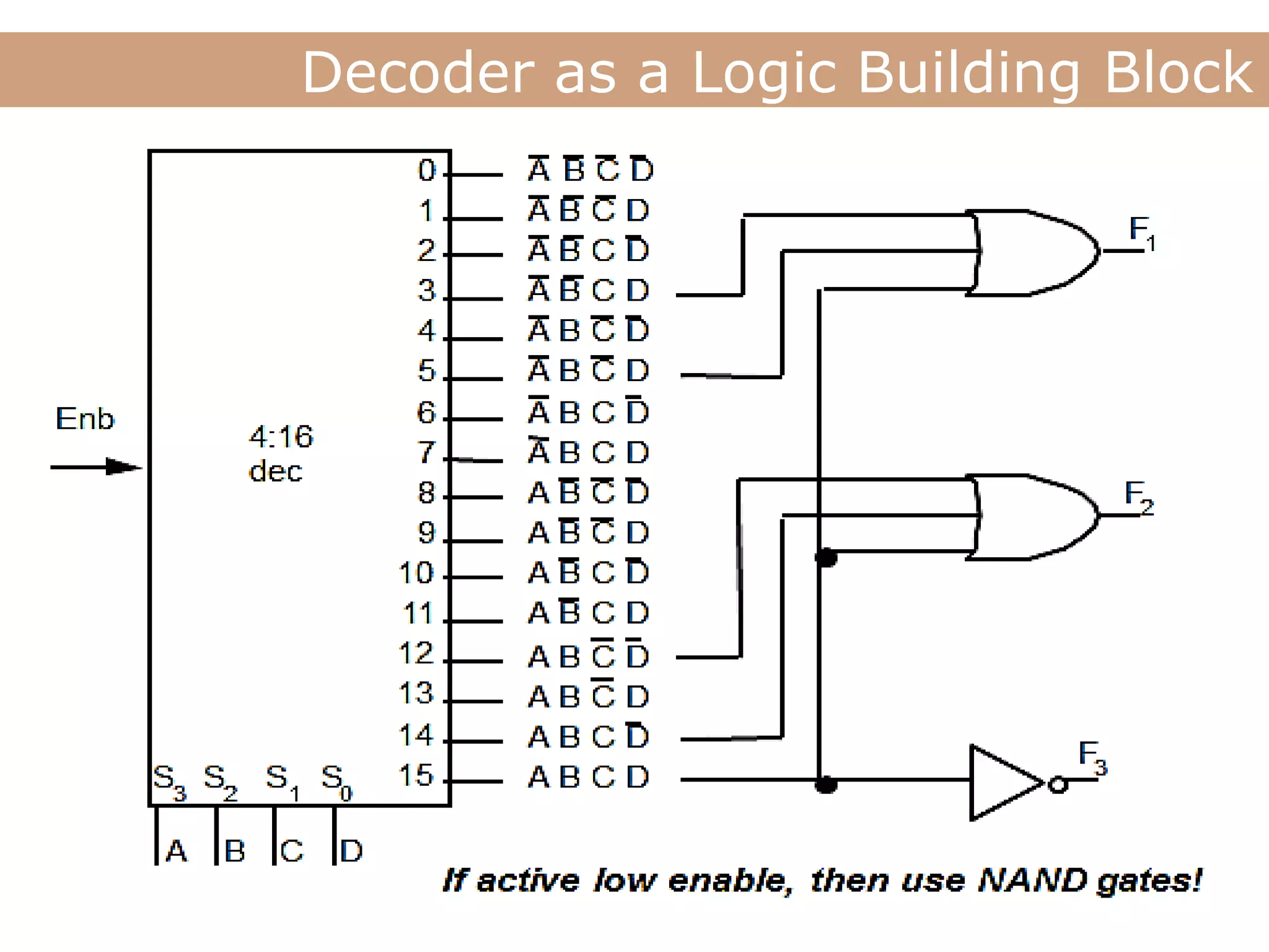
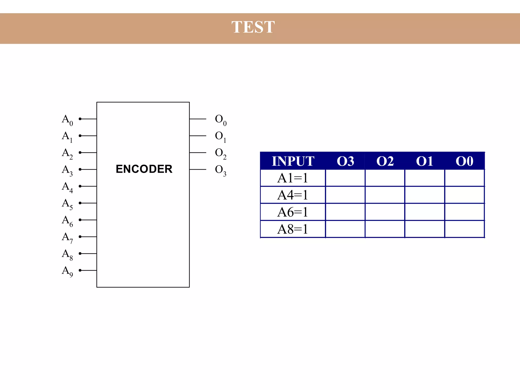

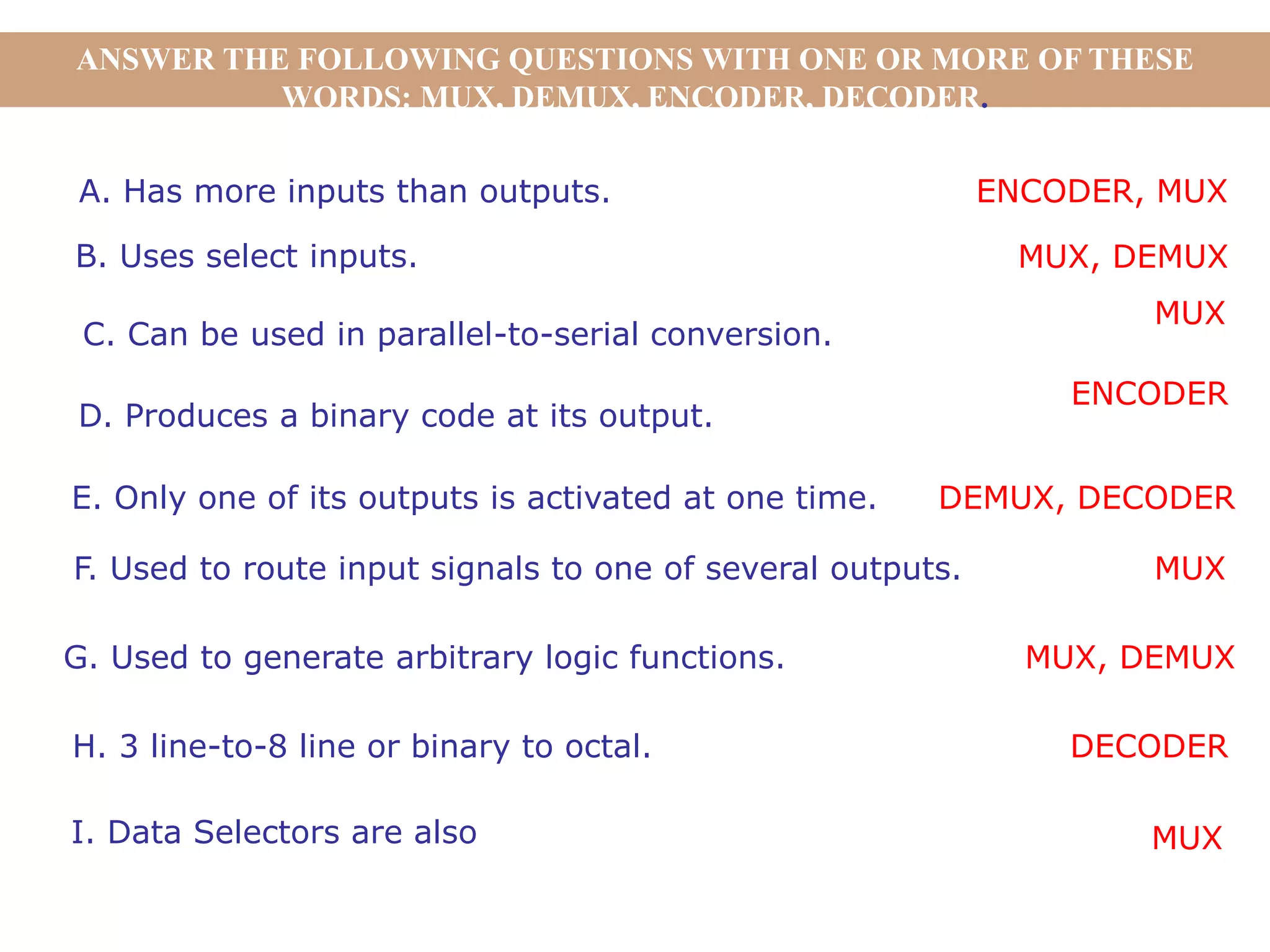

The document discusses encoders, decoders, multiplexers (MUX), and how they can be used to implement digital logic functions. It provides examples of using 4-to-1, 8-to-1 and 10-to-1 MUX to implement functions. It also gives examples of 4-to-2, 8-to-3 and 10-to-4 encoders. Decoder examples include a 2-to-4 and 3-to-8 binary decoder. The document explains how decoders can be used as logic building blocks to realize Boolean functions. It poses questions to be answered using terms like MUX, DEMUX, encoder, decoder.


