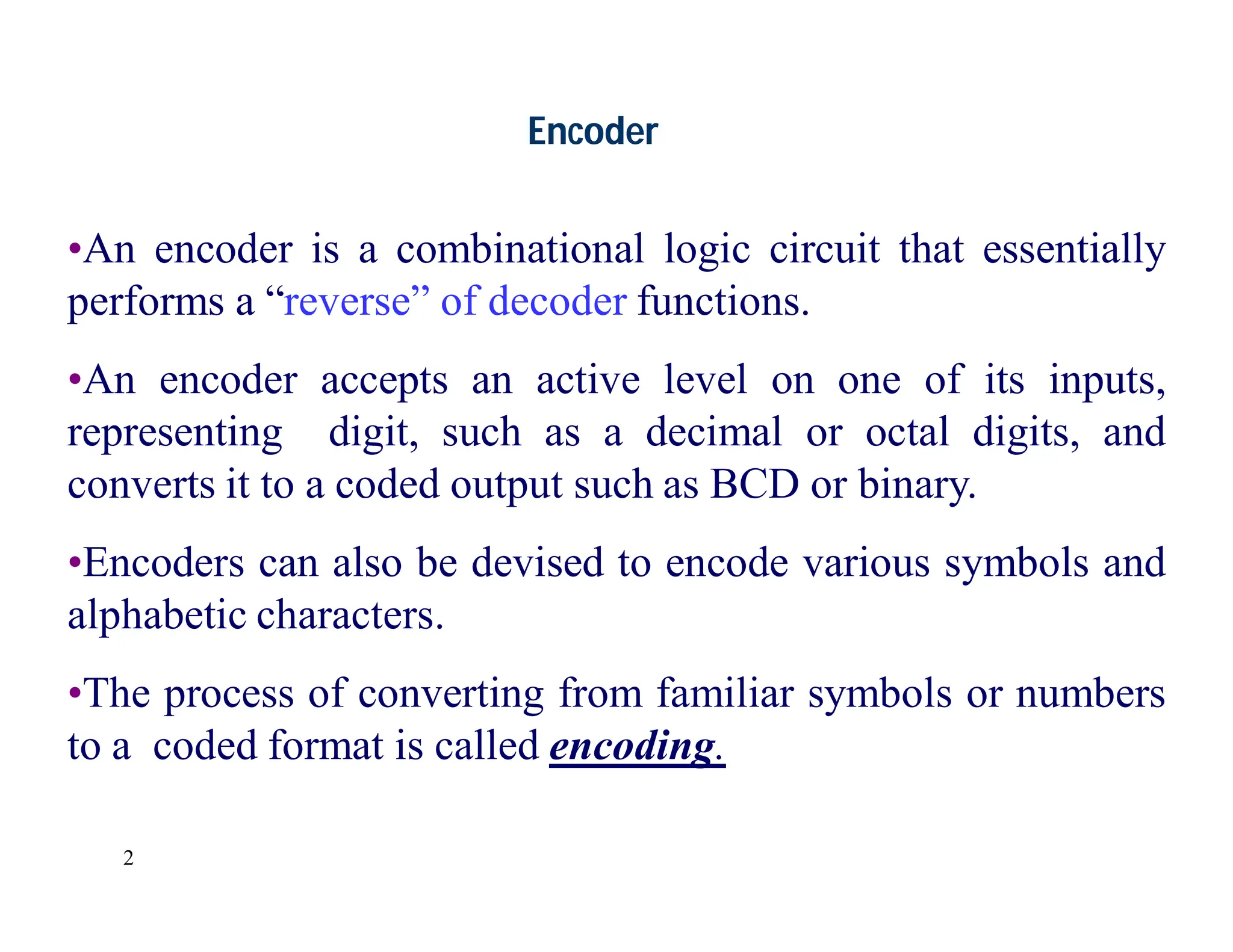
An encoder is a combinational logic circuit that converts active inputs, representing digits or symbols, into coded outputs like binary or BCD. Priority encoders not only encode input signals but also determine precedence among multiple active inputs, with a valid bit indicating whether any input is active. Key applications include digital encoders for keyboards and various encode-decode operations in electronic systems.
2
Encoder
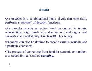
•An encoder isa combinational logic circuit that essentially
performs a “reverse” of decoder functions.
•An encoder accepts an active level on one of its inputs,
representing digit, such as a decimal or octal digits, and
converts it to a coded output such as BCD or binary.
•Encoders can also be devised to encode various symbols and
alphabetic characters.
•The process of converting from familiar symbols or numbers
to a coded format is called encoding.
3.
3
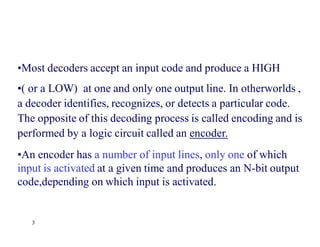
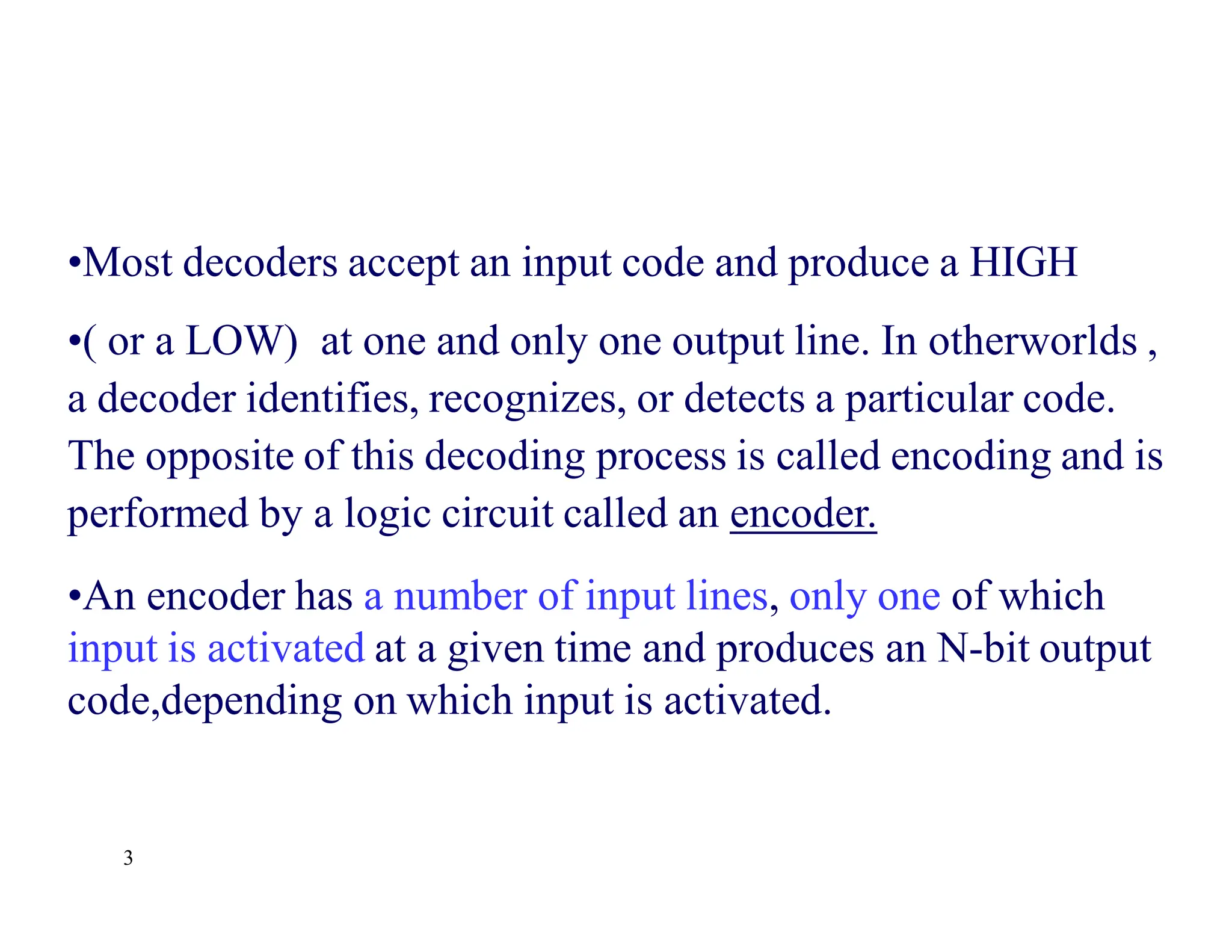
•Most decoders acceptan input code and produce a HIGH
•( or a LOW) at one and only one output line. In otherworlds ,
a decoder identifies, recognizes, or detects a particular code.
The opposite of this decoding process is called encoding and is
performed by a logic circuit called an encoder.
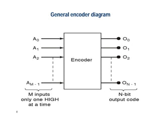
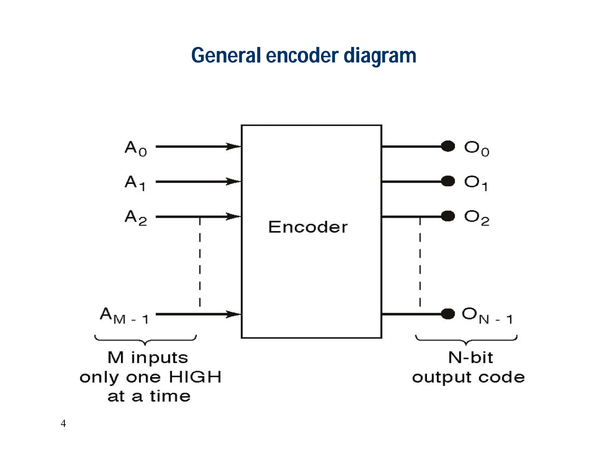
•An encoder has a number of input lines, only one of which
input is activated at a given time and produces an N-bit output
code,depending on which input is activated.
6
A low atany single input will produce the output binary code corresponding to that
input. For instance , a low at A3’ will produce O2 =0, O1=1 and O0 =1, which is
binary code for 3. Ao’ is not connected to the logic gates because the encoder
outputs always be normally at 0000 when none of the inputs is LOW
Truth table for octal-to binary encoder [8-line- 3-line ]
7.
7
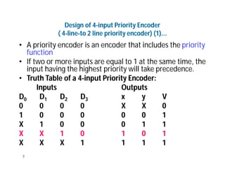
Design of 4-inputPriority Encoder
( 4-line-to 2 line priority encoder) (1)...
• A priority encoder is an encoder that includes the priority
function
• If two or more inputs are equal to 1 at the same time, the
input having the highest priority will take precedence.
• Truth Table of a 4-input Priority Encoder:
Inputs Outputs
D0 D1 D2 D3 x y V
0 0 0 0 X X 0
1 0 0 0 0 0 1
X 1 0 0 0 1 1
X X 1 0 1 0 1
X X X 1 1 1 1
8.
8
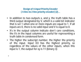
Design of 4-inputPriority Encoder
( 4-line-to 2 line priority encoder) (2)...
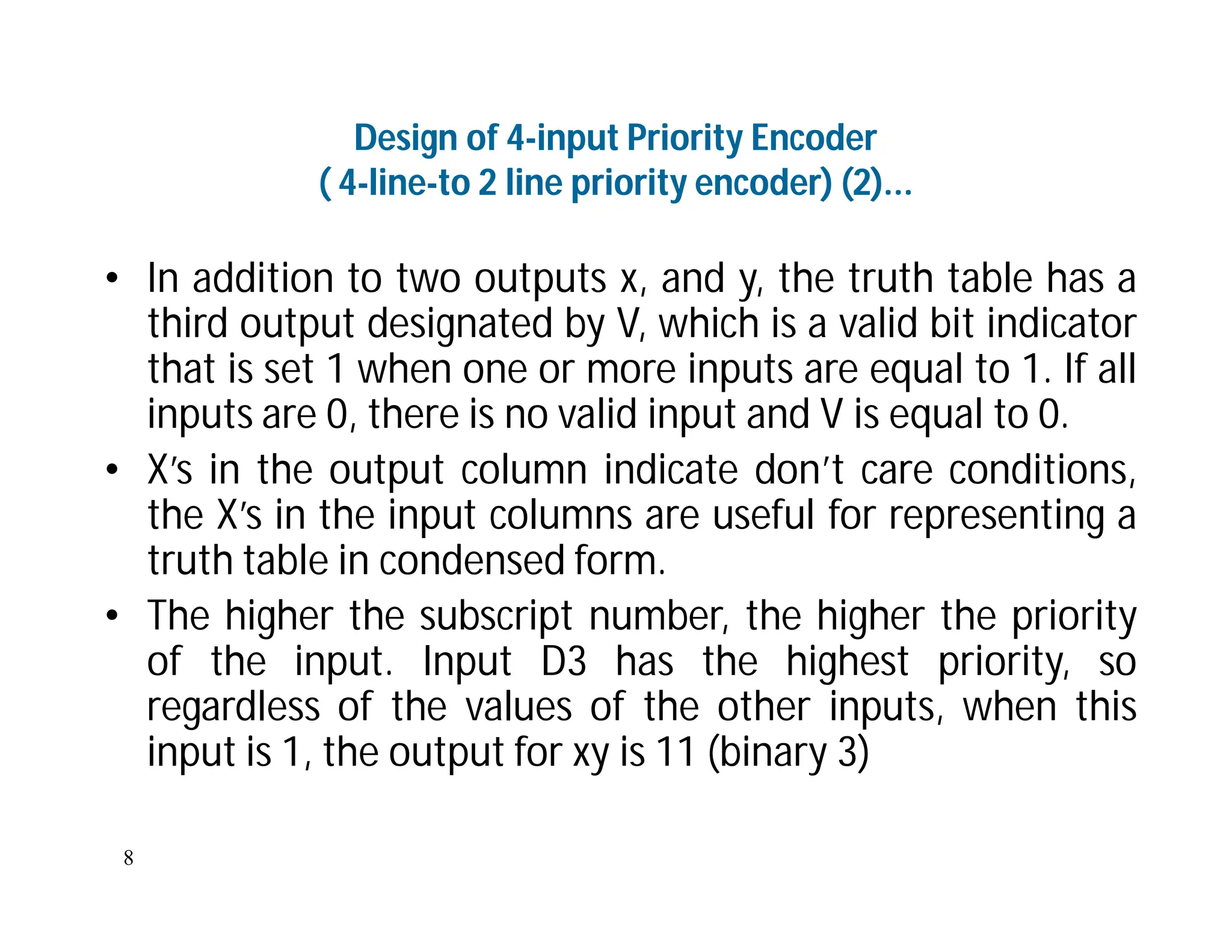
• In addition to two outputs x, and y, the truth table has a
third output designated by V, which is a valid bit indicator
that is set 1 when one or more inputs are equal to 1. If all
inputs are 0, there is no valid input and V is equal to 0.
• X’s in the output column indicate don’t care conditions,
the X’s in the input columns are useful for representing a
truth table in condensed form.
• The higher the subscript number, the higher the priority
of the input. Input D3 has the highest priority, so
regardless of the values of the other inputs, when this
input is 1, the output for xy is 11 (binary 3)
9.
9
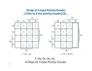
Design of 4-inputPriority Encoder
( 4-line-to 2 line priority encoder) (3)...
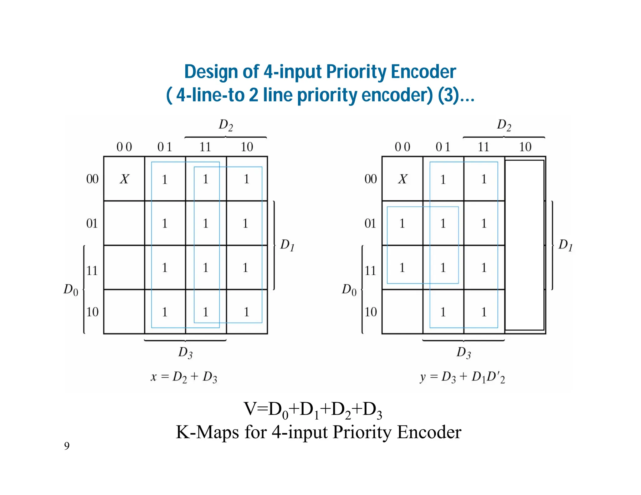
V=D0+D1+D2+D3
K-Maps for 4-input Priority Encoder
10.
10
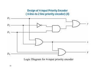
Design of 4-inputPriority Encoder
( 4-line-to 2 line priority encoder) (4)
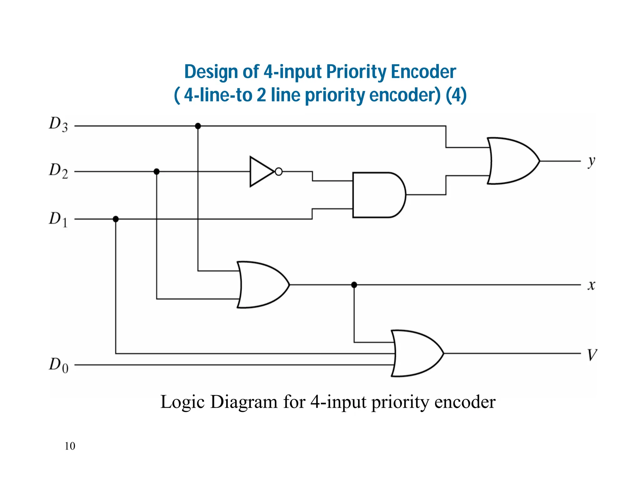
Logic Diagram for 4-input priority encoder
11.
11
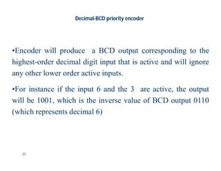
Decimal-BCD priority encoder
•Encoderwill produce a BCD output corresponding to the
highest-order decimal digit input that is active and will ignore
any other lower order active inputs.
•For instance if the input 6 and the 3 are active, the output
will be 1001, which is the inverse value of BCD output 0110
(which represents decimal 6)
12.
12
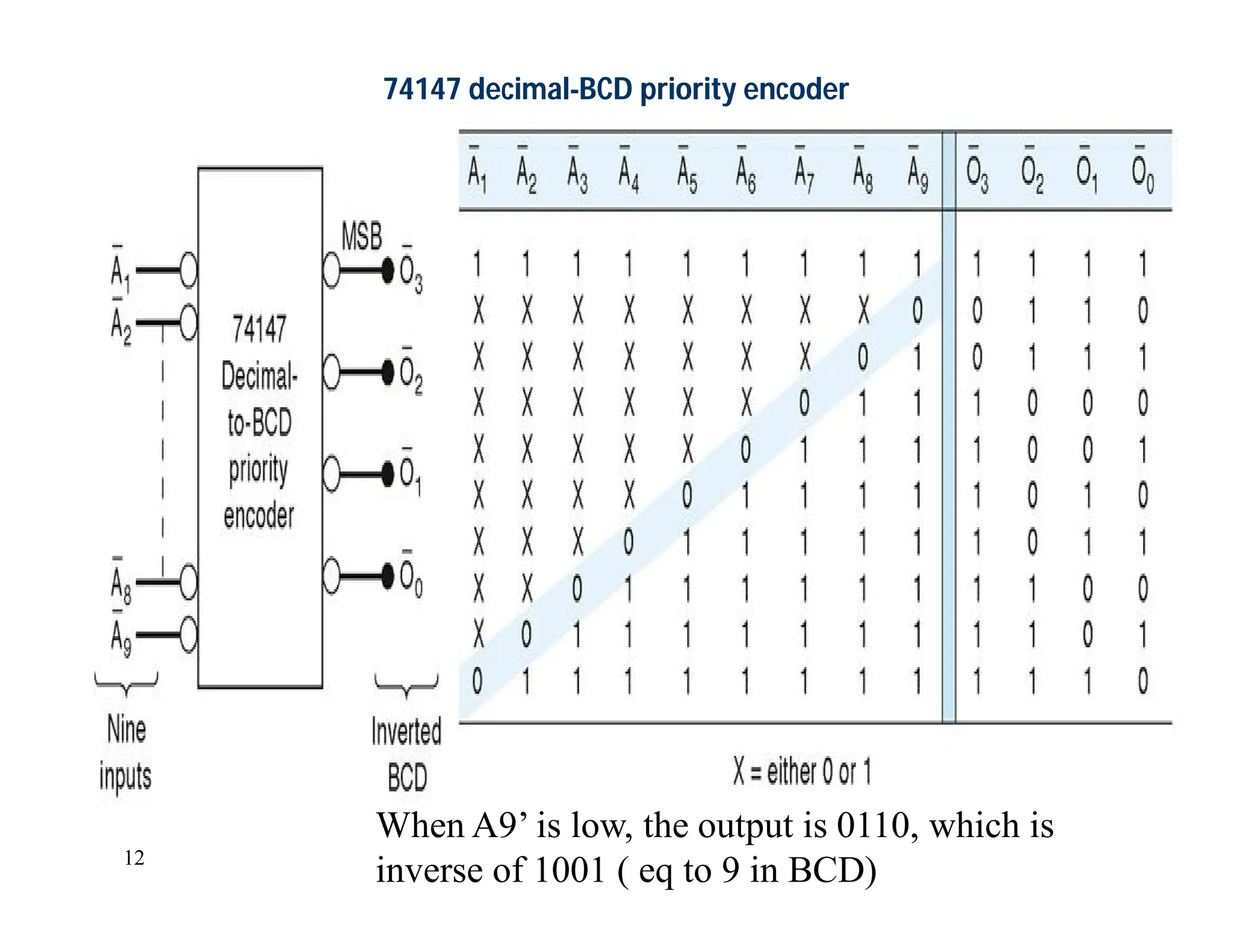
74147 decimal-BCD priorityencoder
When A9’ is low, the output is 0110, which is
inverse of 1001 ( eq to 9 in BCD)
13.
13
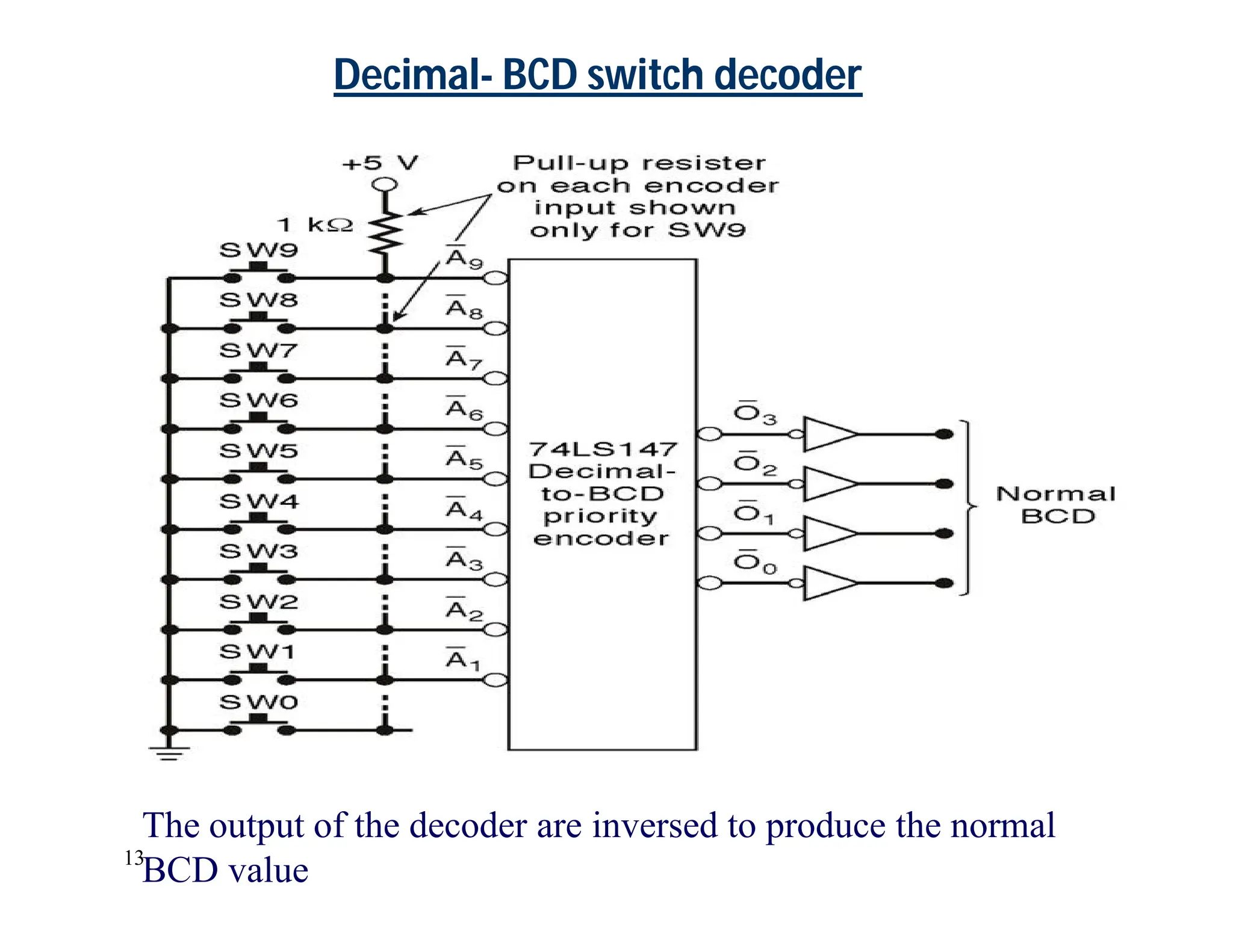
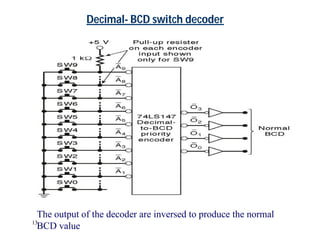
Decimal- BCD switchdecoder
The output of the decoder are inversed to produce the normal
BCD value
14.
14
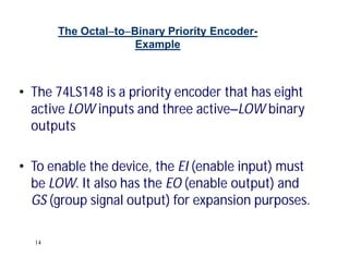
The OctaltoBinary PriorityEncoder-
Example
• The 74LS148 is a priority encoder that has eight
active LOW inputs and three activeLOW binary
outputs
• To enable the device, the EI (enable input) must
be LOW. It also has the EO (enable output) and
GS (group signal output) for expansion purposes.
16
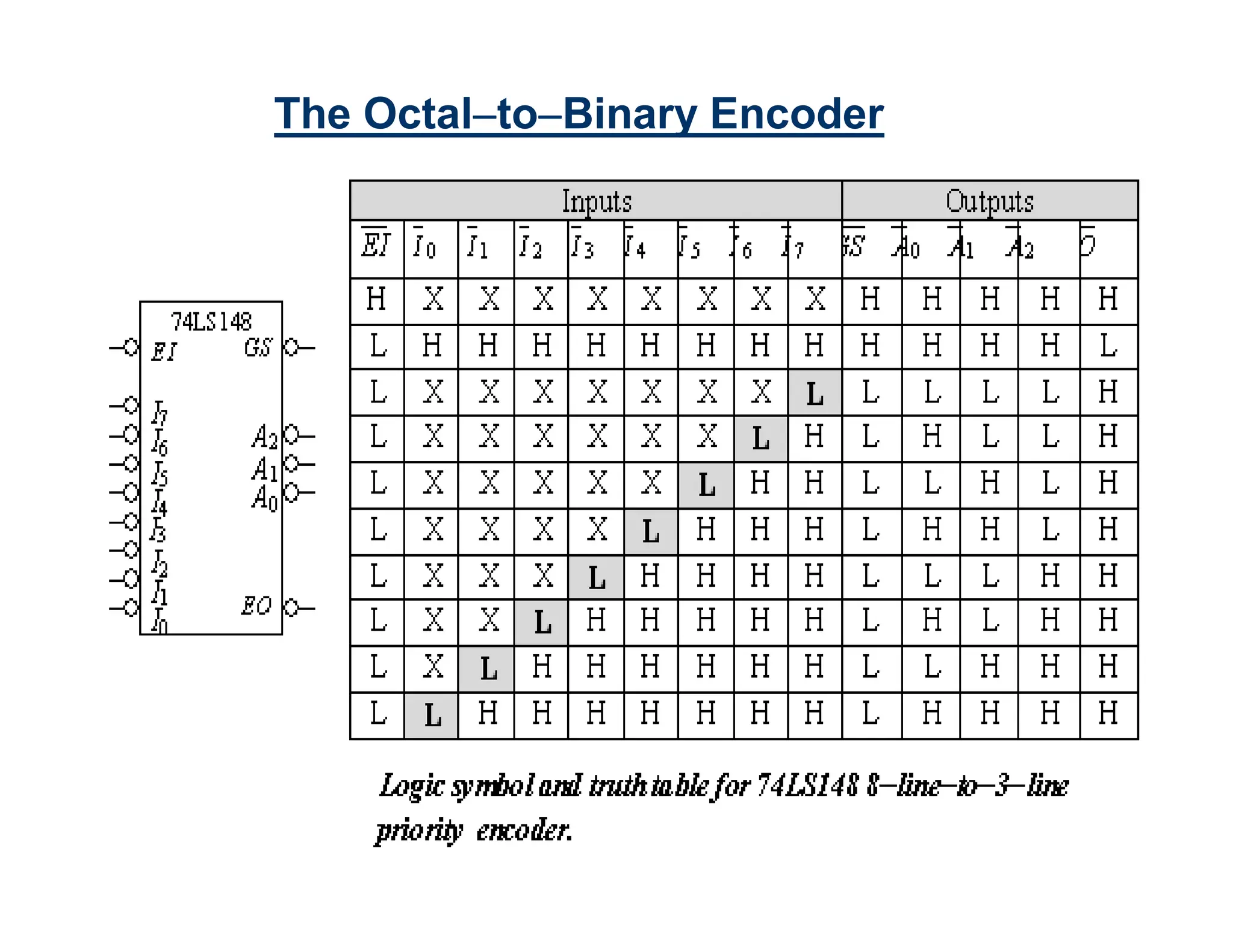
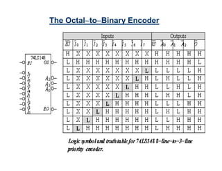
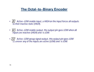
The OctaltoBinary Encoder
•ActiveLOW enable input, a HIGH on the input forces all outputs
to their inactive state (HIGH).
• ActiveLOW enable output, the output pin goes LOW when all
inputs are inactive (HIGH) and is LOW.
• ActiveLOW group signal output, this output pin goes LOW
whenever any of the inputs are active (LOW) and is LOW.
17.
17
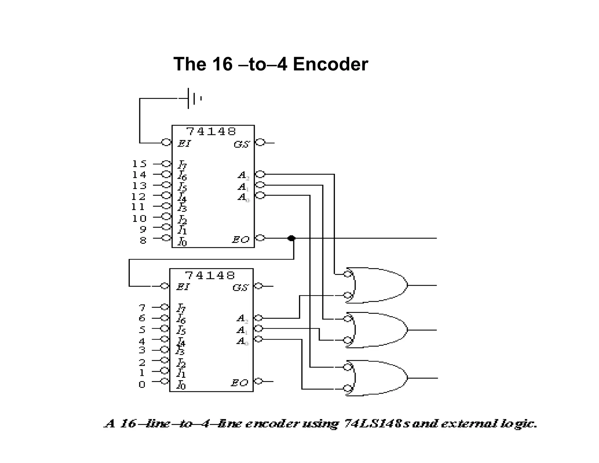
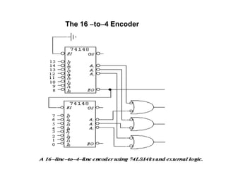
The 74LS148 canbe expanded to a 16lineto4line encoder by
connecting the EO of the higherorder encoder to the EI of the
lowerorder encoder and negativeORing the corresponding
binary outputs as shown
The 16 to4 Encoder
20
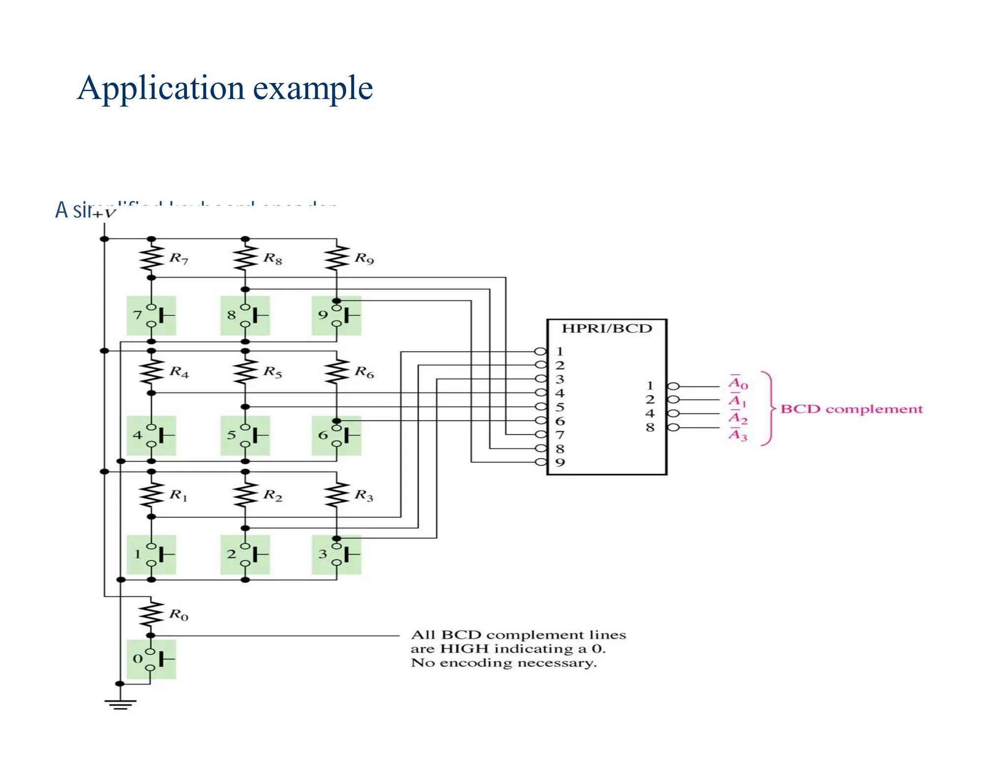
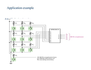
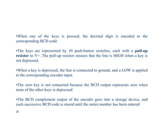
•When one ofthe keys is pressed, the decimal digit is encoded to the
corresponding BCD code
•The keys are represented by 10 push-button switches, each with a pull-up
resistor to V+. The pull-up resistor ensures that the line is HIGH when a key is
not depressed.
•When a key is depressed, the line is connected to ground, and a LOW is applied
to the corresponding encoder input.
•The zero key is not connected because the BCD output represents zero when
none of the other keys is depressed
•The BCD complement output of the encoder goes into a storage device, and
each successive BCD code is stored until the entire number has been entered
21.
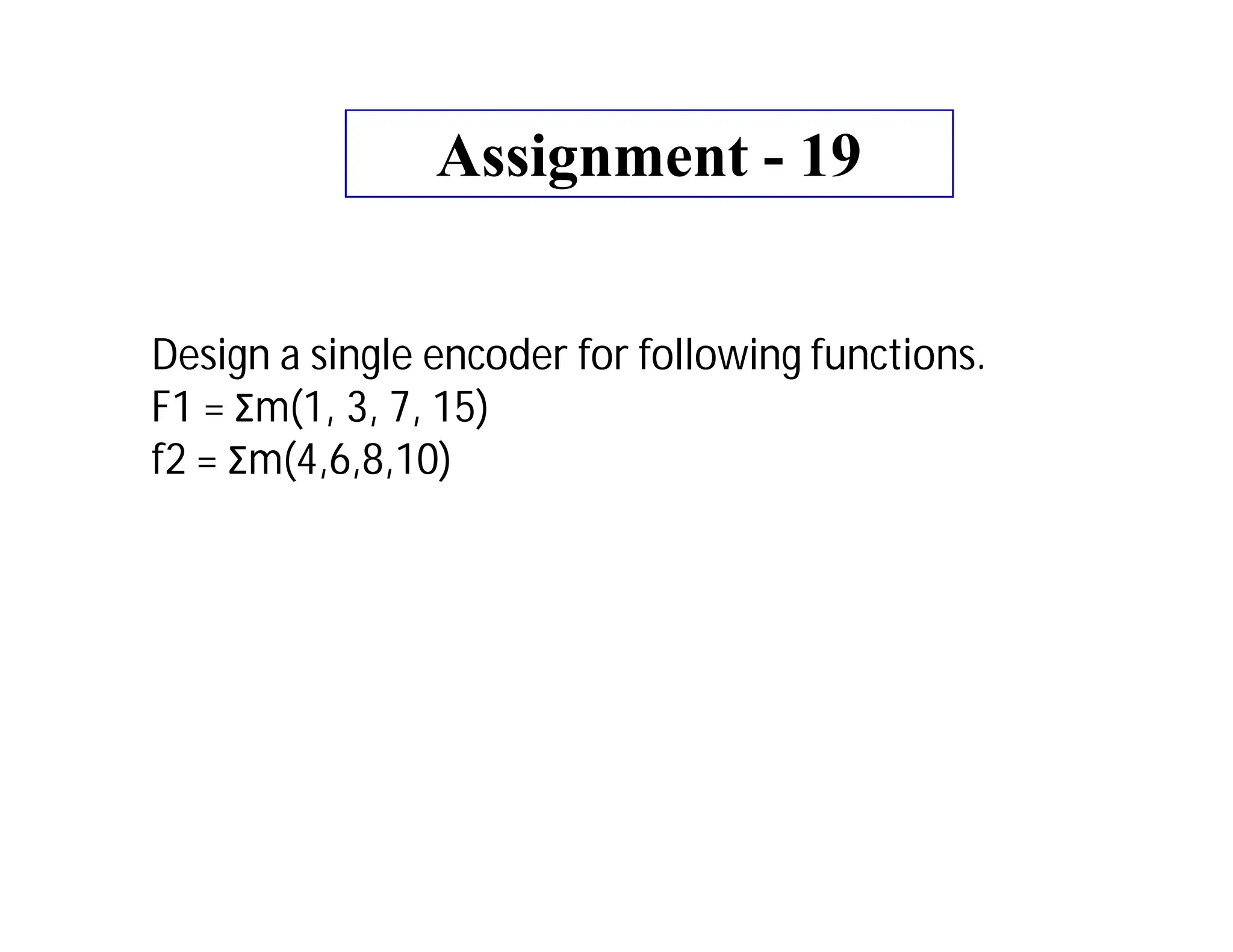
Assignment - 19
Designa single encoder for following functions.
F1 = Σm(1, 3, 7, 15)
f2 = Σm(4,6,8,10)
![5
Logic circuit for octal-to binary encoder [8-line-
3-line ]](https://image.slidesharecdn.com/digital-electronics9-240402051637-d421ddd6/85/digital-electronics_9-encoder-and-decoder-pdf-5-320.jpg)
![6
A low at any single input will produce the output binary code corresponding to that
input. For instance , a low at A3’ will produce O2 =0, O1=1 and O0 =1, which is
binary code for 3. Ao’ is not connected to the logic gates because the encoder
outputs always be normally at 0000 when none of the inputs is LOW
Truth table for octal-to binary encoder [8-line- 3-line ]](https://image.slidesharecdn.com/digital-electronics9-240402051637-d421ddd6/85/digital-electronics_9-encoder-and-decoder-pdf-6-320.jpg)


![5
Logic circuit for octal-to binary encoder [8-line-
3-line ]](https://image.slidesharecdn.com/digital-electronics9-240402051637-d421ddd6/75/digital-electronics_9-encoder-and-decoder-pdf-5-2048.jpg)
![6
A low at any single input will produce the output binary code corresponding to that
input. For instance , a low at A3’ will produce O2 =0, O1=1 and O0 =1, which is
binary code for 3. Ao’ is not connected to the logic gates because the encoder
outputs always be normally at 0000 when none of the inputs is LOW
Truth table for octal-to binary encoder [8-line- 3-line ]](https://image.slidesharecdn.com/digital-electronics9-240402051637-d421ddd6/75/digital-electronics_9-encoder-and-decoder-pdf-6-2048.jpg)