Download to read offline
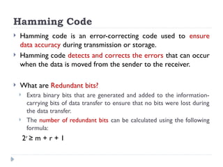
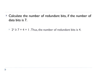

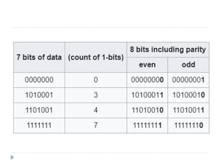
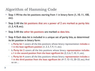
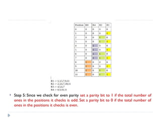
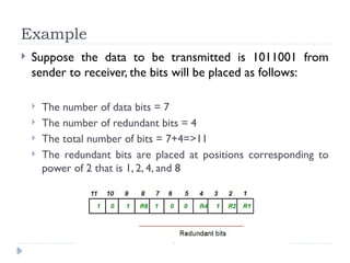


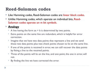
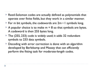


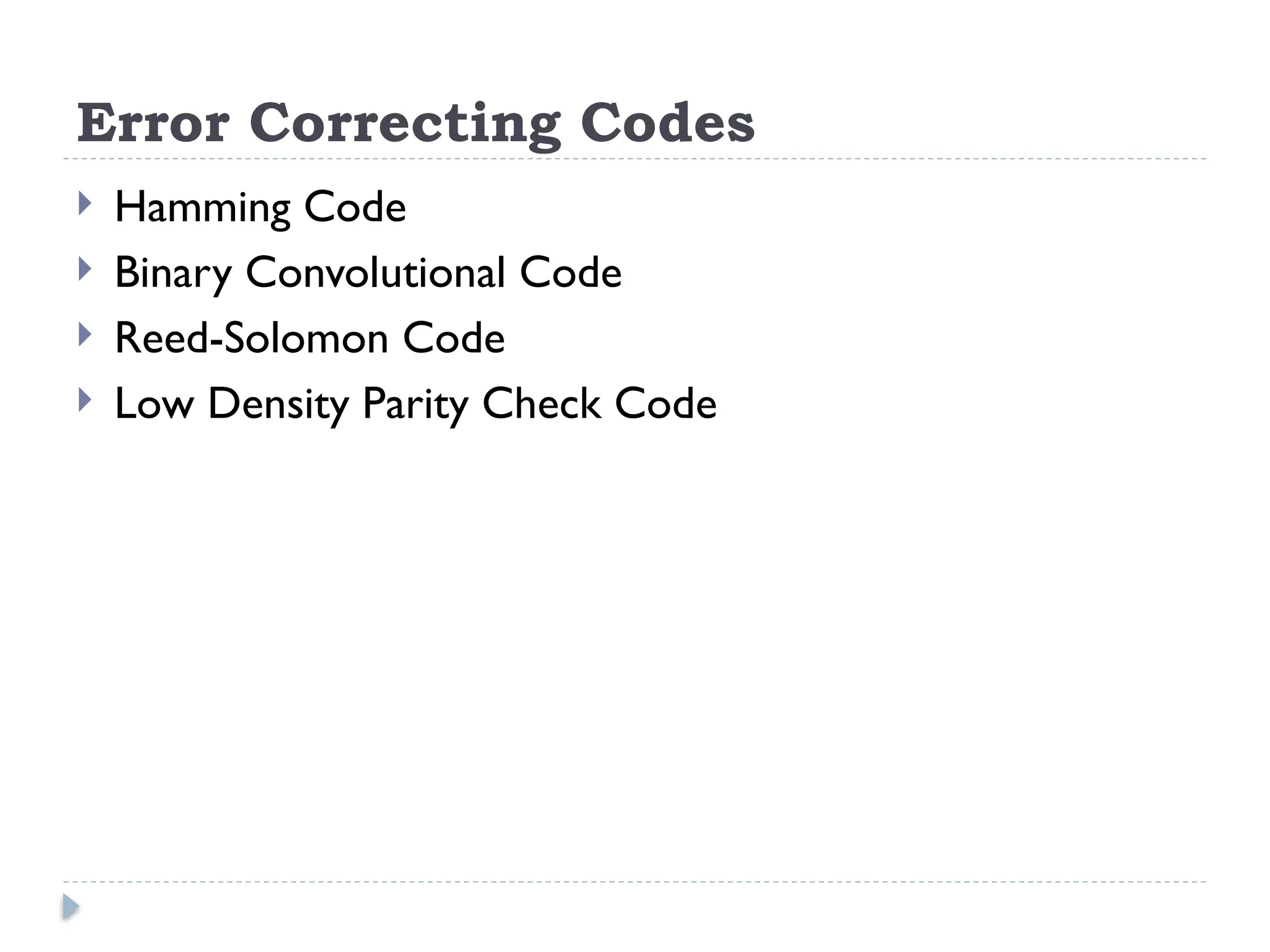
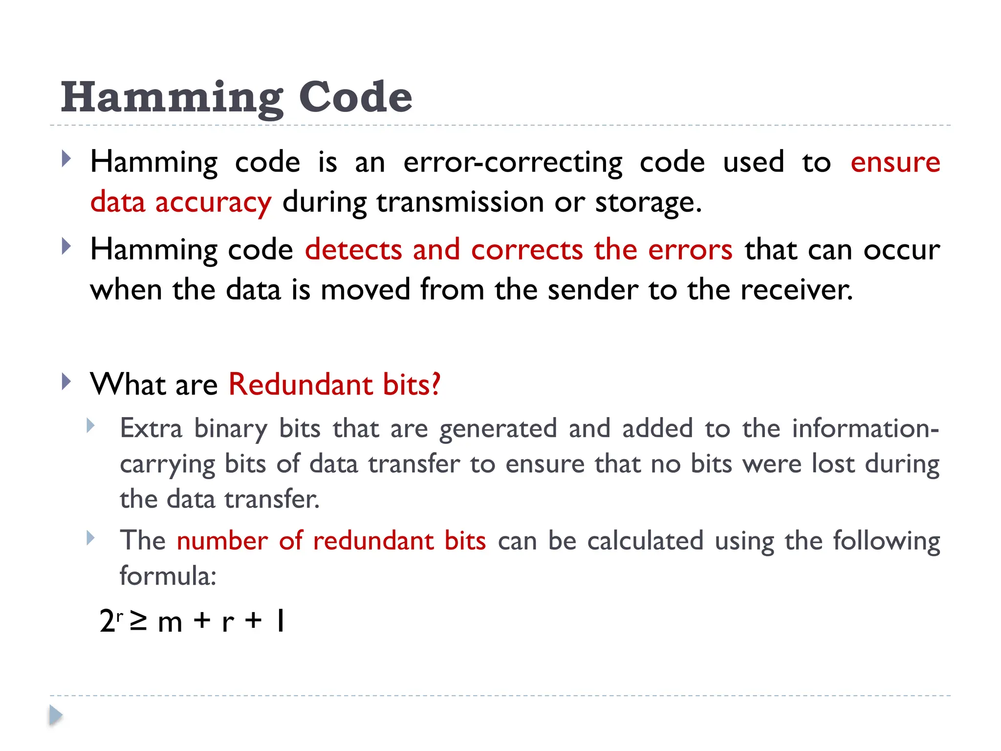
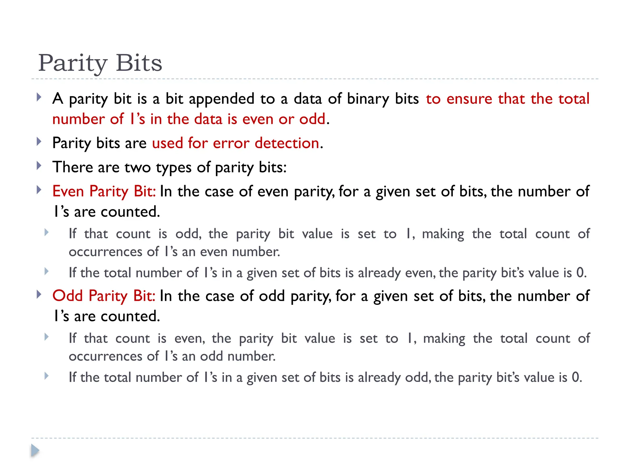
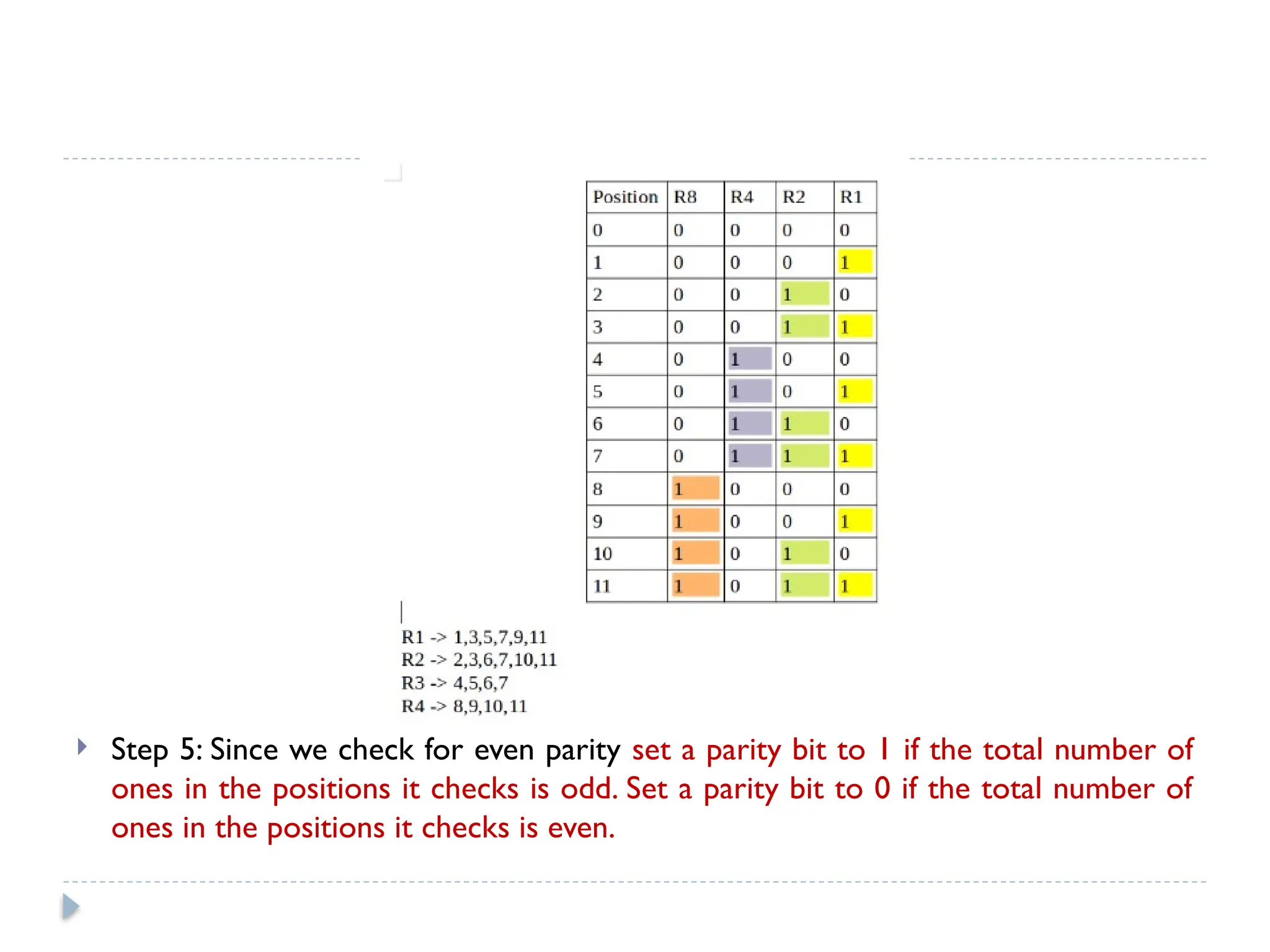
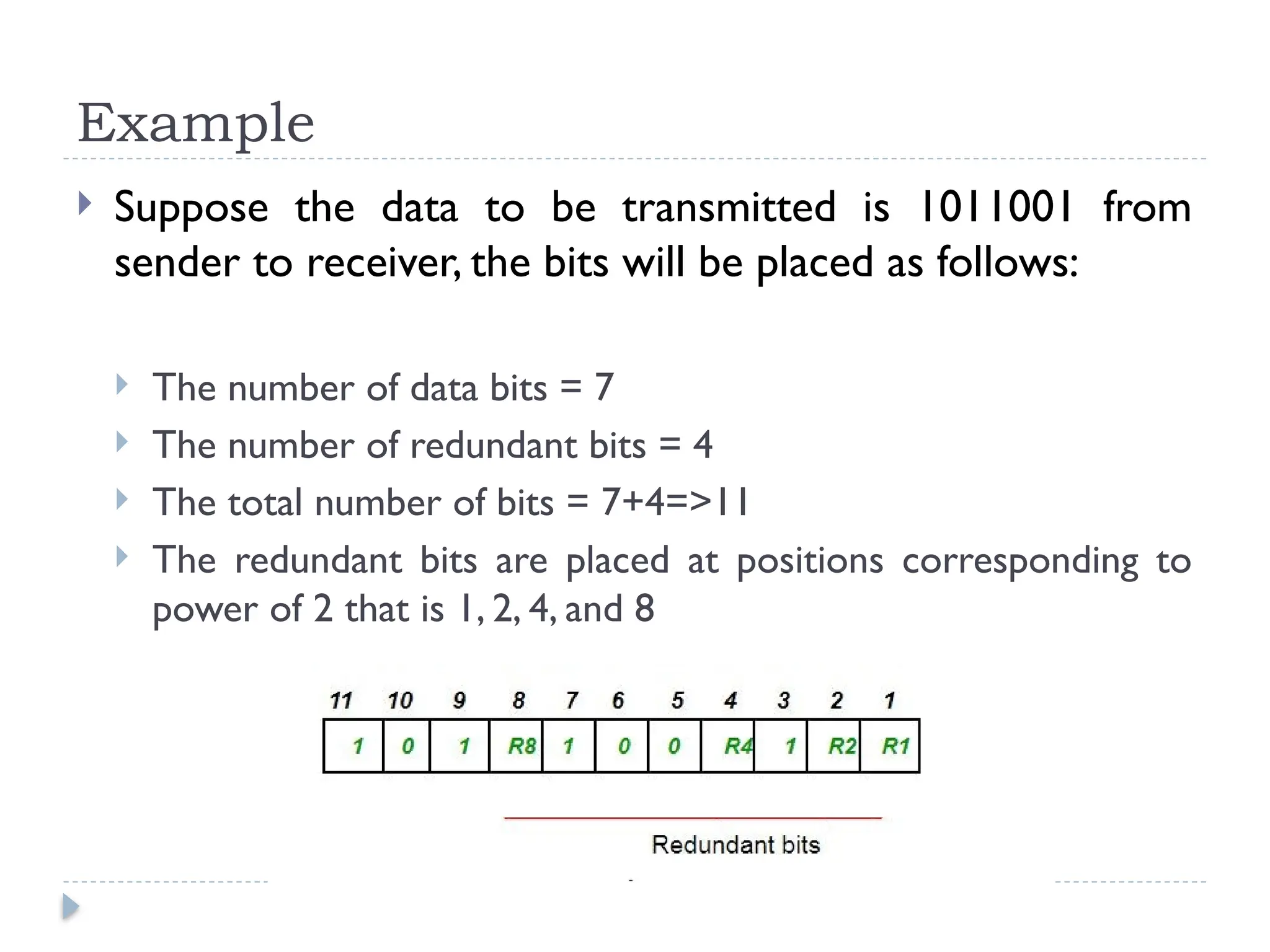
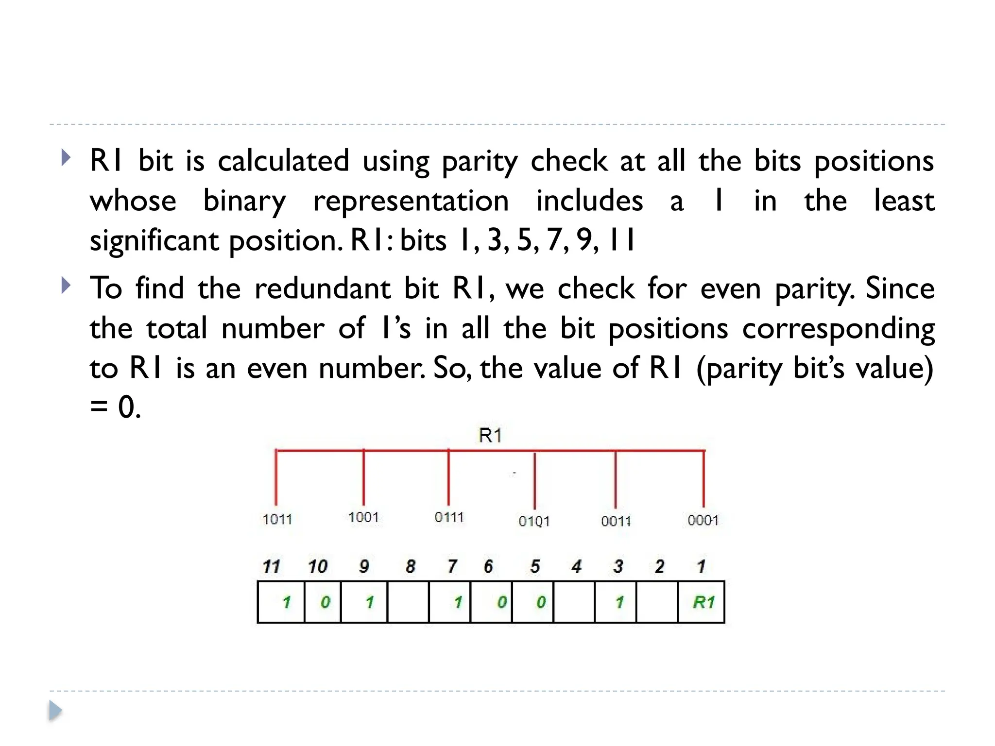

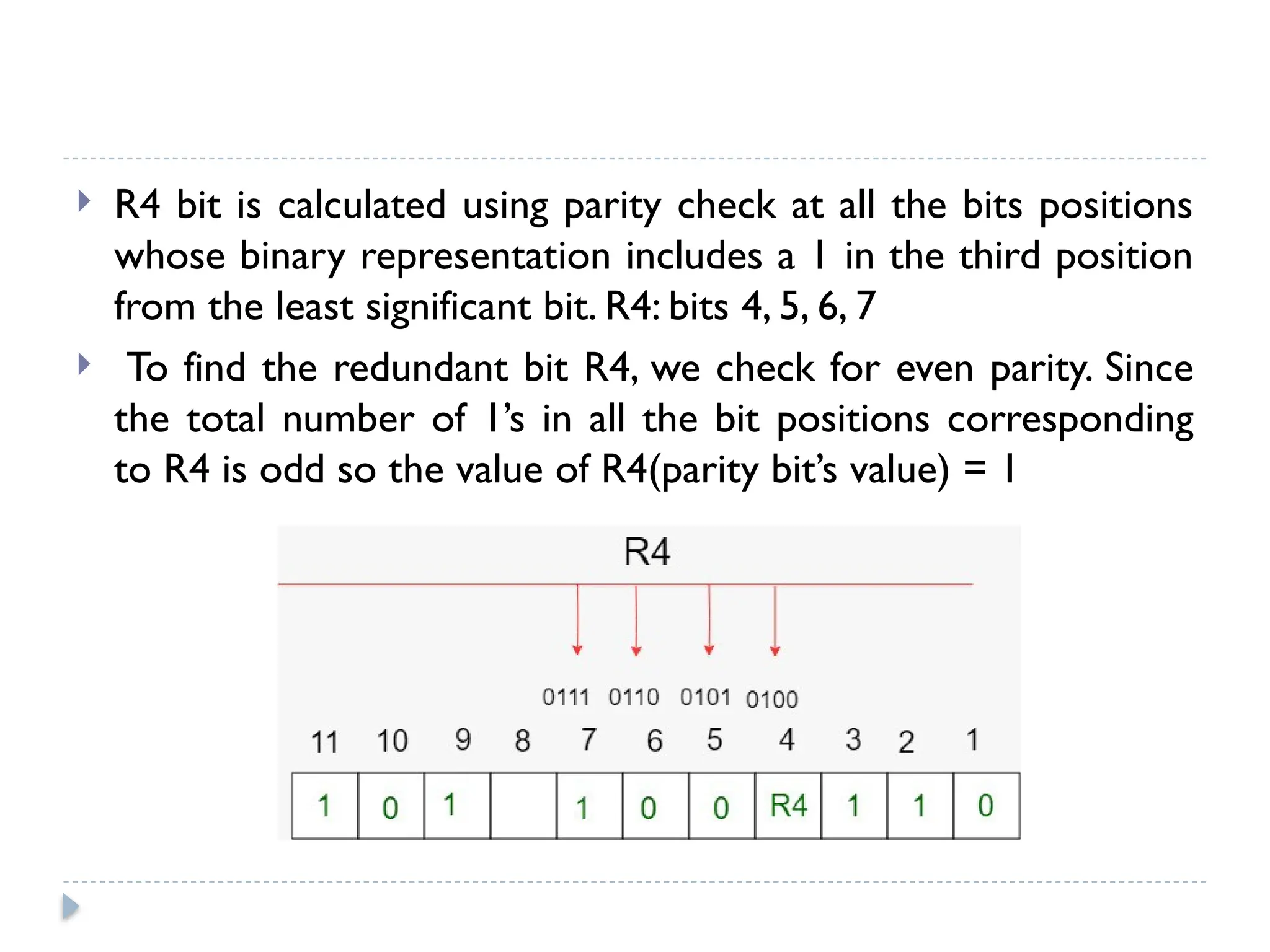


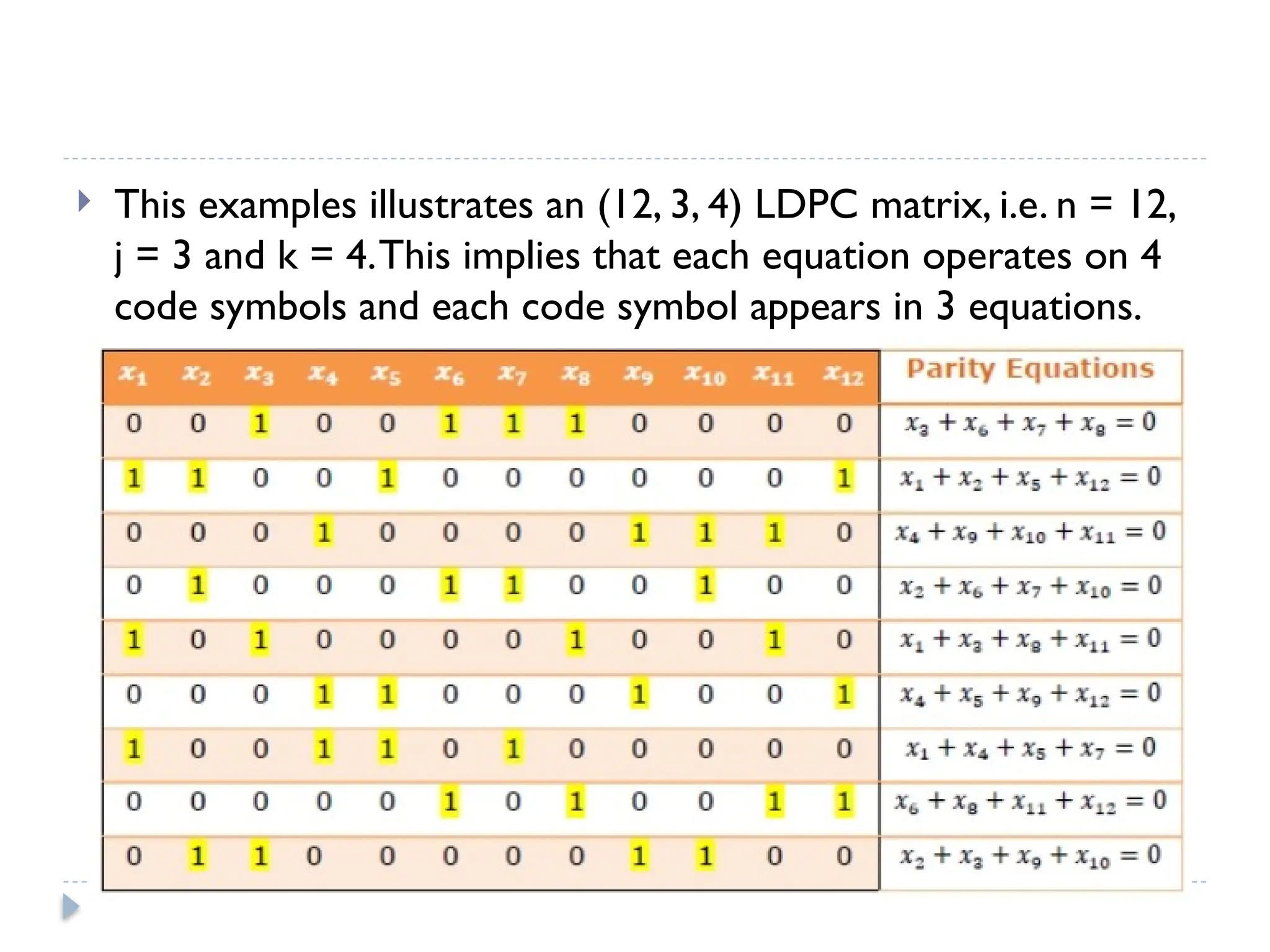

The document discusses error-correcting and error-detecting codes, including Hamming code, Reed-Solomon code, and low-density parity check (LDPC) code. It explains the concepts of redundant bits and parity bits, detailing how they facilitate data accuracy during transmission or storage. Additionally, it covers various algorithms used for these codes, their applications, and advantages along with error-detection mechanisms like checksums.


