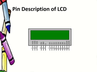
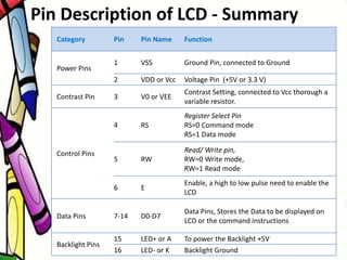
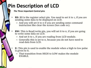
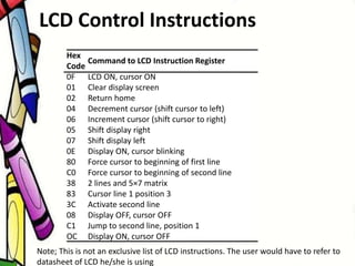
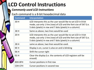
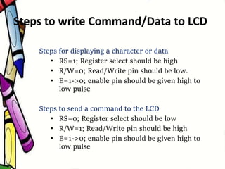
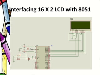
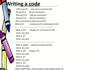
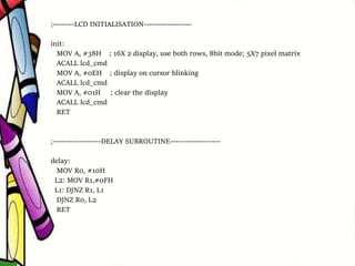
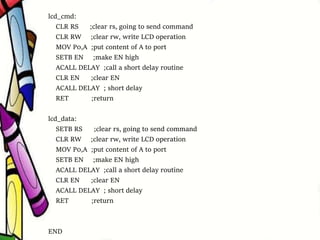
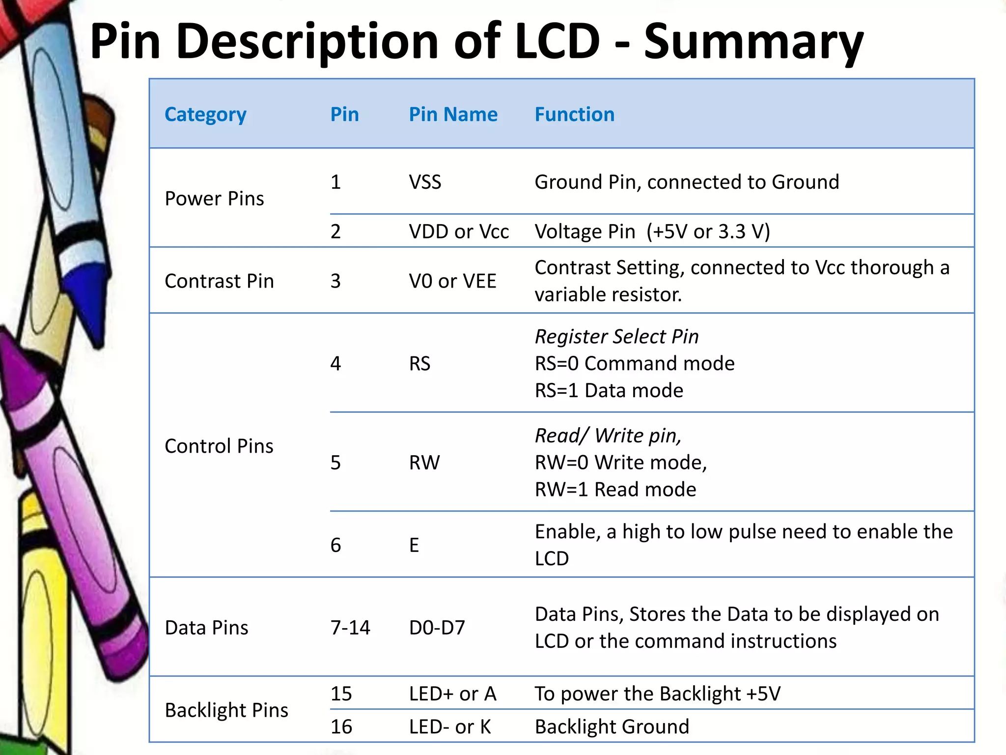
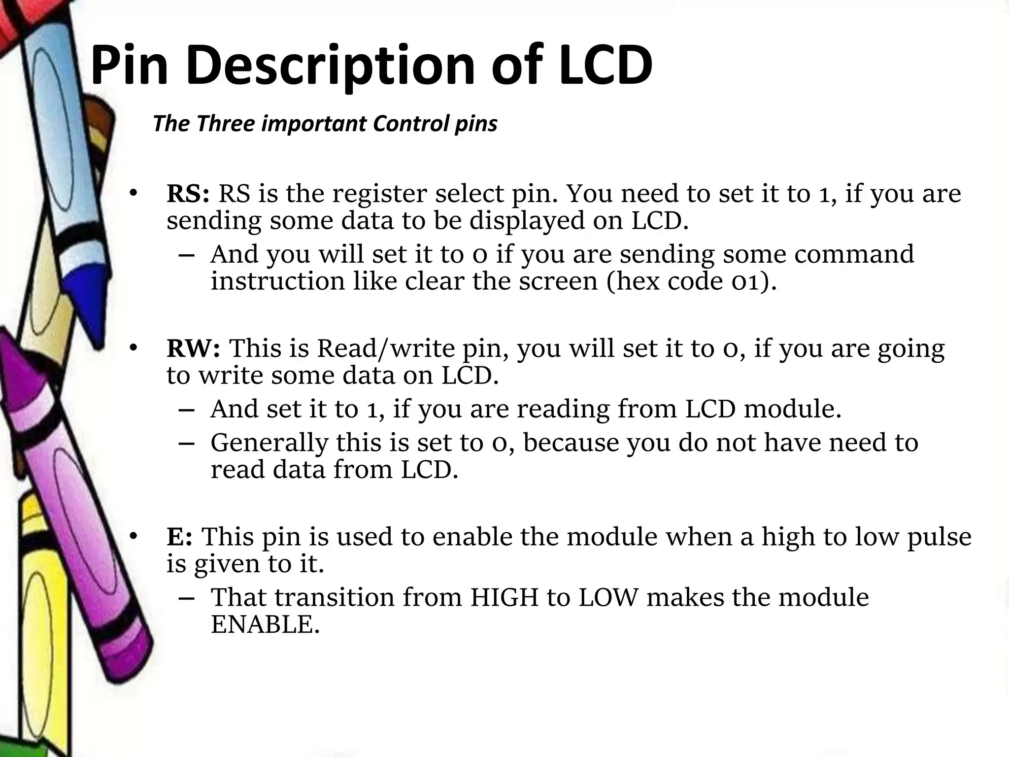
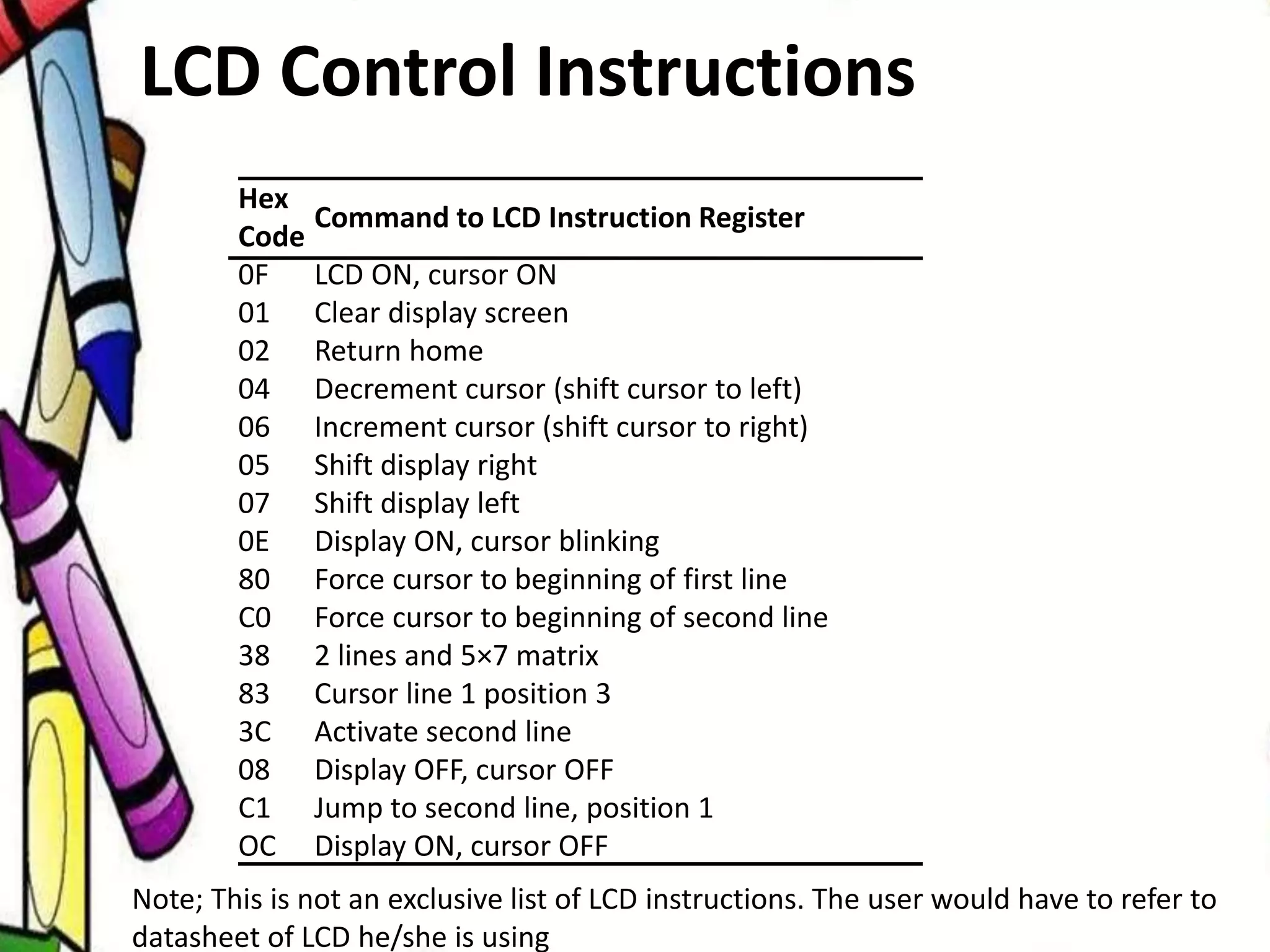
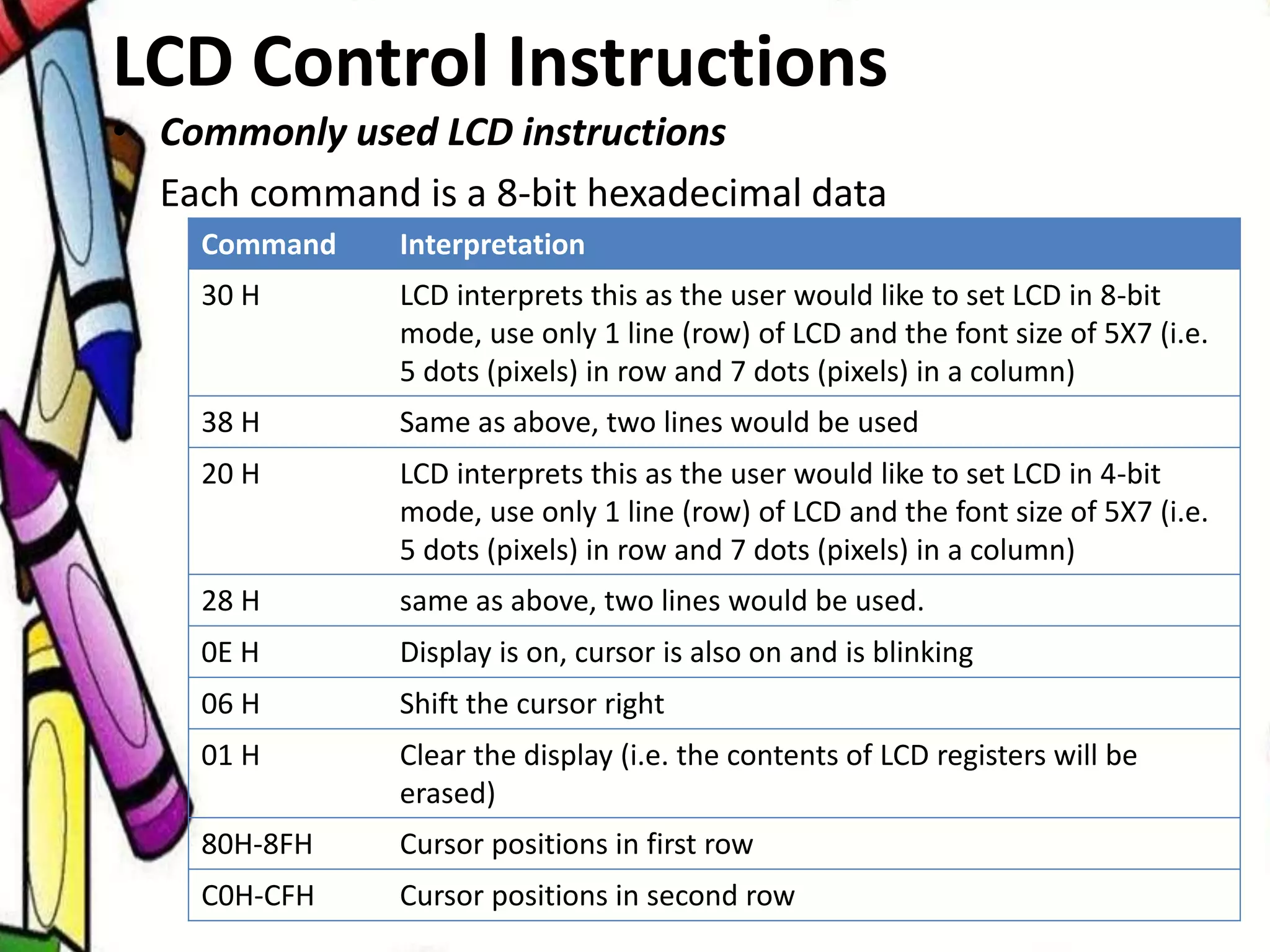
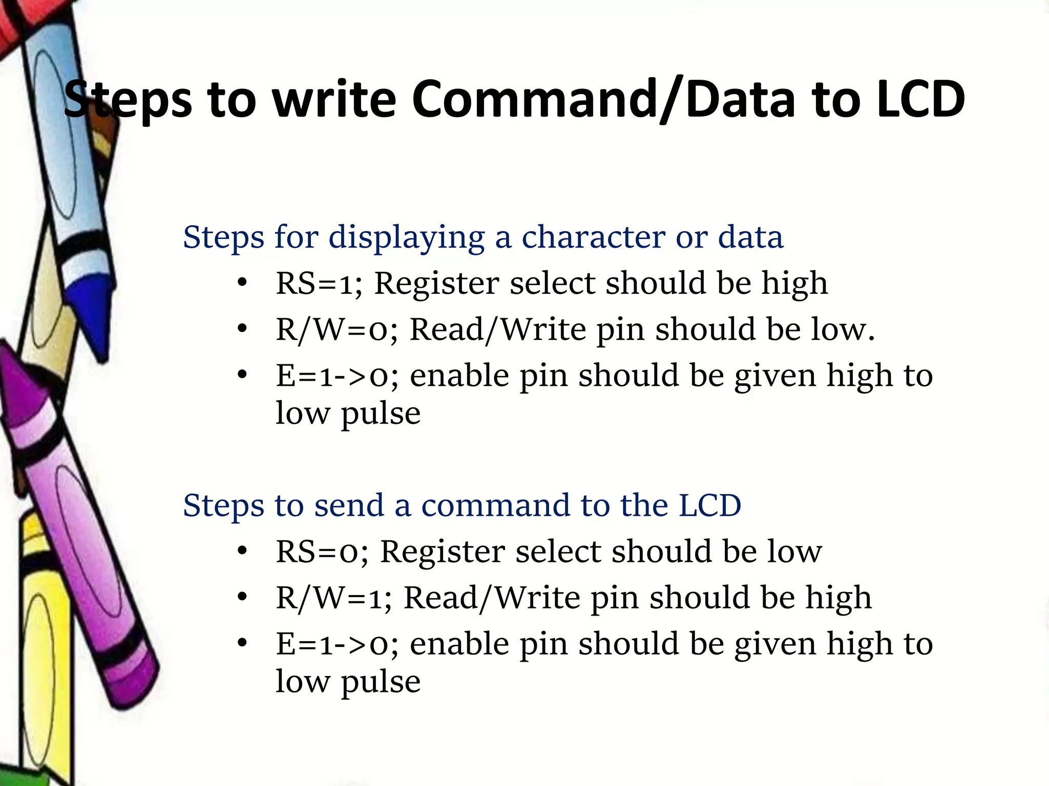
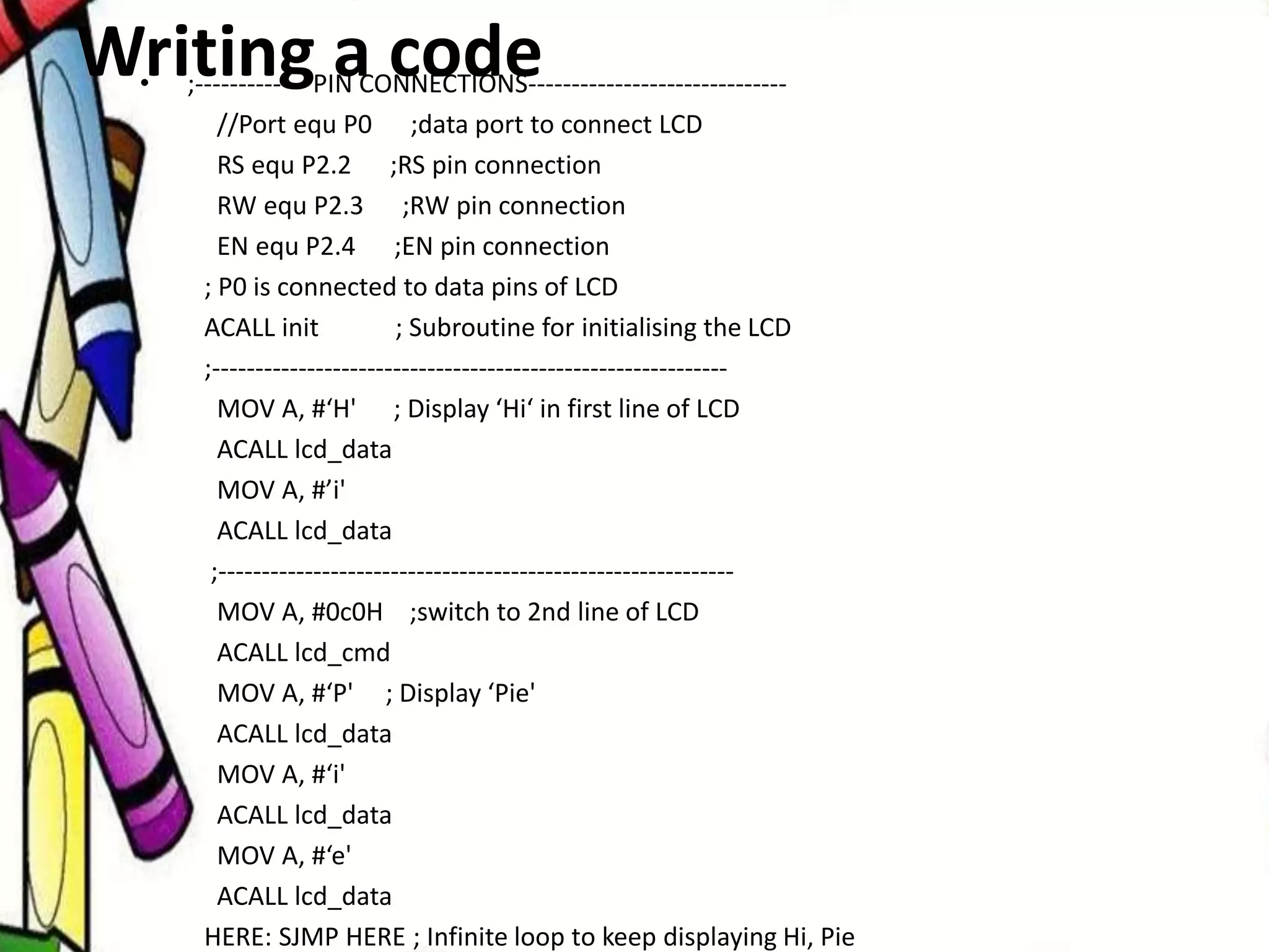
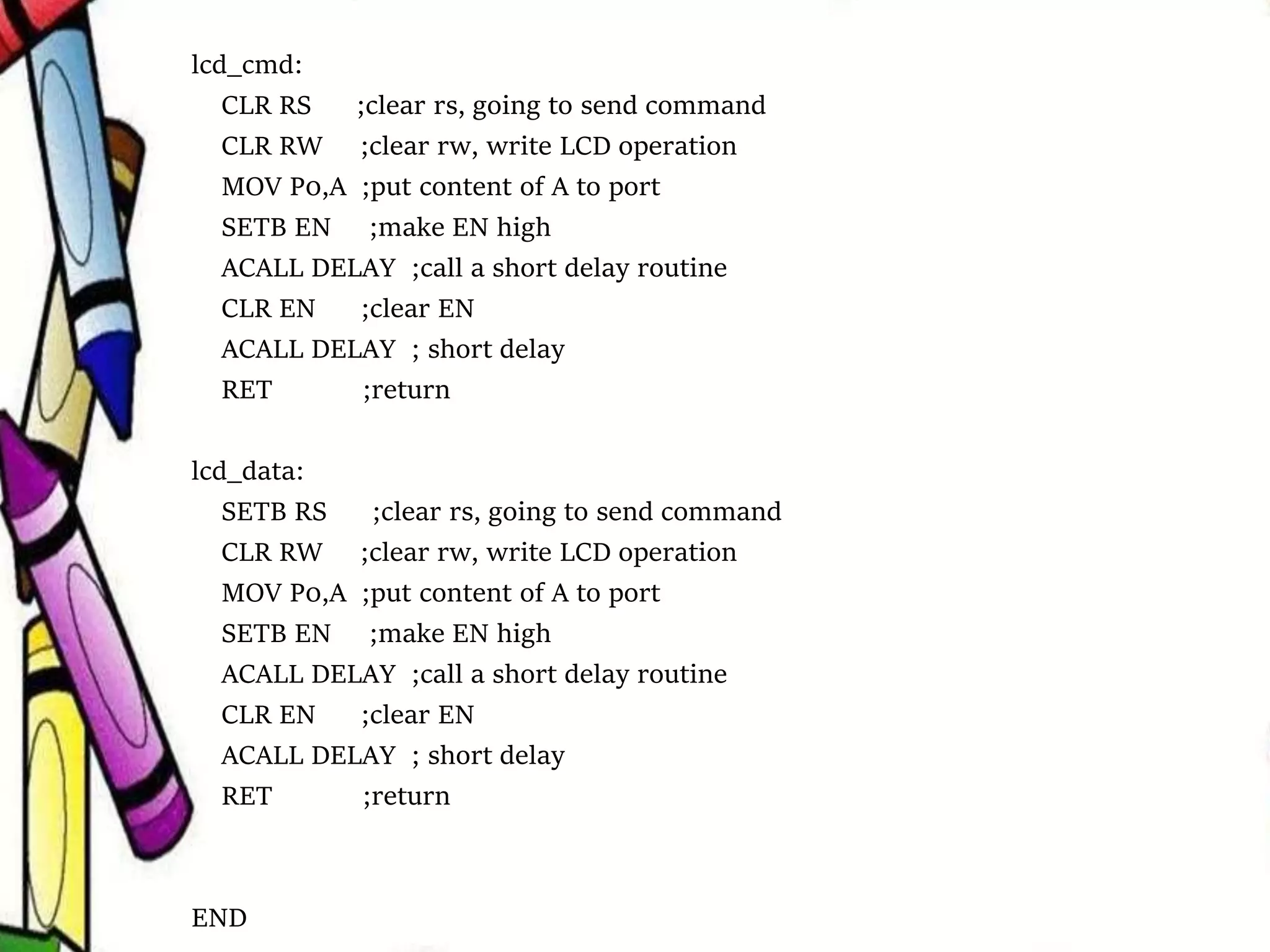
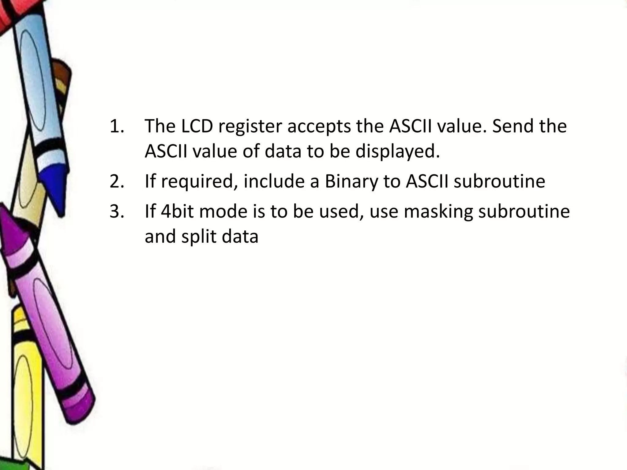
KEMBAR78
LCD Interacing with 8051 | PPTX
LCD Interfacing
with 8051
.
Lecture Notes: 27th March 2018- 3rd April 2018
Sudhanshu Janwadkar
TA, ECED, SVNIT
Points to discuss
• Character LCD basics
• Pin description of Character LCD
• Understanding how to use character LCD
• Interfacing with 8051
Introduction
• LCD stands for Liquid Crystal Display
• Two types:
 Character LCD
 Graphics LCD
• Used to:
 Display information
• LCDs are being widely used, because they are:
 Easy to Interface
 Easy to procure
 Well documented
LCD is finding widespread use. Factors:
• The declining prices of LCD
• The ability to display numbers, characters, and
graphics
• Incorporation of a refreshing controller into the
LCD, thereby relieving the CPU of the task of
refreshing the LCD
• Ease of programming
Introduction
• A 16×2 Liquid Crystal Display can display 32
characters at a time in two rows
 16 characters in one row
• Each character in the display of size 5×7 pixel
matrix, (although this matrix differs for
different 16×2 LCD modules)
• There are 16 pins in the LCD module
Introduction
• 5 X7 pixel matrix would mean there are 5 pixels in a
row and 7 pixels in a column for display.
• Each pixel will either be black or white to represent a
character.
• The character ‘A’ would be represented as shown:
Introduction
Pin Description of LCD
• Holding LCD towards the user, Leftmost pin is
pin 1 and rightmost is pin 16
• We can divide the LCD pins into following
categories:
 Power (Pin 1,2 and 3)
 Control (Pin 4, 5 and 6)
 Data (Pin 7 through 14)
 Backlight (Pin 15 and 16)
Pin Description of LCD
Power pins
• Pin 1 is Ground. Connect it to 0v.
• Pin 2 is VDD.
 You can connect it to 5V or 3.3V (Refer to data sheet of the LCD)
• Pin 3 is contrast pin.
 A typical character LCD would have black text in foreground
and green/blue background.
 Contrast would control the difference between background and
foreground.
 This pin would be required to make the display more dark (text
dark)
 Connect Pin3 to centre point of potentiometer and adjust
contrast with help of potentiometer.
Pin Description of LCD
Control pins
• Pin 4 is RS (Register Select)
 The LCDs have two registers: Command register & data
register in a DDRAM memory.
 The control instructions like clear LCD or shift the cursor, are
stored in Command Register (also called instruction register)
 The data to be displayed such as say some character ‘a’ ‘2’ etc, it
is stored in Data register.
 If you need to send command, select the command register by
setting RS=0. If you need to send data to be displayed on LCD,
you would select data register by setting RS=1
Pin Description of LCD
Control pins
• Pin Number 5 is Read/Write pin.
 Typically, you do not read from LCD, you write to it. Hence,
most of times, you would connect it to ground.
 If you would have to read data previously stored it LCD, you
would have to make this pin 1
• Pin 6 is enable pin.
 The transitions of Enable pin are seen as clock for the registers
in LCD. Data is latched on LCD only on positive edges of the
clock (Enable pin).
 Whenever you need to write data or command to a LCD or read
from LCD, you would have to generate a high-to low pulse on
Enable pin . Seeing this transition on LCD, the LCD would
understand that it has to perform a read/write operation.
Pin Description of LCD
Data pins
• Pin Number 7 through 14 are data pins.
 You can use 4 data pins or 8 data pins, for programming your
LCD.
 If you decide to use LCD in 4-bit mode, although the
data/command that is to be send to the LCD is of 8-bits width,
you would first send lower 4 bits of data and later you would
send the upper 4-bits, i.e. lower nibble followed by the upper
one.
 Why would one go for 4-bit mode when he/she can send 8-bit
data, at a time?
 4-bit mode saves 4-pins of the microcontroller. If your
application involves multiple interfaces, it would be wiser to
save the pins of microcontroller.
 If the application has no constraints on number of pins, it would
be wiser to use 8-bit mode as LCD writing is a slow speed
operation. You do not send any high priority data to LCD. Hence,
to make your application work faster, prefer 8-bit mode in this
case.
Pin Description of LCD
Backlight pins
• Pins 15 and 16 are for controlling Backlight
 Backlight is a LED in background.
 To control the backlight, you would connect pin 15 to positive
voltage and pin 16 to negative voltage. This would light up the
LED.
 Always connect this via a resistor, as you do not want to
damage the LED.
Pin Description of LCD
Category Pin Pin Name Function
Power Pins
1 VSS Ground Pin, connected to Ground
2 VDD or Vcc Voltage Pin (+5V or 3.3 V)
Contrast Pin 3 V0 or VEE
Contrast Setting, connected to Vcc thorough a
variable resistor.
Control Pins
4 RS
Register Select Pin
RS=0 Command mode
RS=1 Data mode
5 RW
Read/ Write pin,
RW=0 Write mode,
RW=1 Read mode
6 E
Enable, a high to low pulse need to enable the
LCD
Data Pins 7-14 D0-D7
Data Pins, Stores the Data to be displayed on
LCD or the command instructions
Backlight Pins
15 LED+ or A To power the Backlight +5V
16 LED- or K Backlight Ground
Pin Description of LCD - Summary
• RS: RS is the register select pin. You need to set it to 1, if you are
sending some data to be displayed on LCD.
– And you will set it to 0 if you are sending some command
instruction like clear the screen (hex code 01).
• RW: This is Read/write pin, you will set it to 0, if you are going
to write some data on LCD.
– And set it to 1, if you are reading from LCD module.
– Generally this is set to 0, because you do not have need to
read data from LCD.
• E: This pin is used to enable the module when a high to low pulse
is given to it.
– That transition from HIGH to LOW makes the module
ENABLE.
The Three important Control pins
Pin Description of LCD
LCD Control Instructions
Hex
Code
Command to LCD Instruction Register
0F LCD ON, cursor ON
01 Clear display screen
02 Return home
04 Decrement cursor (shift cursor to left)
06 Increment cursor (shift cursor to right)
05 Shift display right
07 Shift display left
0E Display ON, cursor blinking
80 Force cursor to beginning of first line
C0 Force cursor to beginning of second line
38 2 lines and 5×7 matrix
83 Cursor line 1 position 3
3C Activate second line
08 Display OFF, cursor OFF
C1 Jump to second line, position 1
OC Display ON, cursor OFF
Note; This is not an exclusive list of LCD instructions. The user would have to refer to
datasheet of LCD he/she is using
• Commonly used LCD instructions
• Each command is a 8-bit hexadecimal data
LCD Control Instructions
Command Interpretation
30 H LCD interprets this as the user would like to set LCD in 8-bit
mode, use only 1 line (row) of LCD and the font size of 5X7 (i.e.
5 dots (pixels) in row and 7 dots (pixels) in a column)
38 H Same as above, two lines would be used
20 H LCD interprets this as the user would like to set LCD in 4-bit
mode, use only 1 line (row) of LCD and the font size of 5X7 (i.e.
5 dots (pixels) in row and 7 dots (pixels) in a column)
28 H same as above, two lines would be used.
0E H Display is on, cursor is also on and is blinking
06 H Shift the cursor right
01 H Clear the display (i.e. the contents of LCD registers will be
erased)
80H-8FH Cursor positions in first row
C0H-CFH Cursor positions in second row
Steps to write Command/Data to LCD
Steps for displaying a character or data
• RS=1; Register select should be high
• R/W=0; Read/Write pin should be low.
• E=1->0; enable pin should be given high to
low pulse
Steps to send a command to the LCD
• RS=0; Register select should be low
• R/W=1; Read/Write pin should be high
• E=1->0; enable pin should be given high to
low pulse
Interfacing 16 X 2 LCD with 8051
Writing a code• ;------------- PIN CONNECTIONS------------------------------
//Port equ P0 ;data port to connect LCD
RS equ P2.2 ;RS pin connection
RW equ P2.3 ;RW pin connection
EN equ P2.4 ;EN pin connection
; P0 is connected to data pins of LCD
ACALL init ; Subroutine for initialising the LCD
;------------------------------------------------------------
MOV A, #‘H' ; Display ‘Hi‘ in first line of LCD
ACALL lcd_data
MOV A, #’i'
ACALL lcd_data
;------------------------------------------------------------
MOV A, #0c0H ;switch to 2nd line of LCD
ACALL lcd_cmd
MOV A, #‘P' ; Display ‘Pie'
ACALL lcd_data
MOV A, #‘i'
ACALL lcd_data
MOV A, #‘e'
ACALL lcd_data
HERE: SJMP HERE ; Infinite loop to keep displaying Hi, Pie
;--------LCD INITIALISATION------------------
init:
MOV A, #38H ; 16X 2 display, use both rows, 8bit mode; 5X7 pixel matrix
ACALL lcd_cmd
MOV A, #0EH ; display on cursor blinking
ACALL lcd_cmd
MOV A, #01H ; clear the display
ACALL lcd_cmd
RET
;------------------DELAY SUBROUTINE-------------------
delay:
MOV R0, #10H
L2: MOV R1,#0FH
L1: DJNZ R1, L1
DJNZ R0, L2
RET
lcd_cmd:
CLR RS ;clear rs, going to send command
CLR RW ;clear rw, write LCD operation
MOV P0,A ;put content of A to port
SETB EN ;make EN high
ACALL DELAY ;call a short delay routine
CLR EN ;clear EN
ACALL DELAY ; short delay
RET ;return
lcd_data:
SETB RS ;clear rs, going to send command
CLR RW ;clear rw, write LCD operation
MOV P0,A ;put content of A to port
SETB EN ;make EN high
ACALL DELAY ;call a short delay routine
CLR EN ;clear EN
ACALL DELAY ; short delay
RET ;return
END
1. The LCD register accepts the ASCII value. Send the
ASCII value of data to be displayed.
2. If required, include a Binary to ASCII subroutine
3. If 4bit mode is to be used, use masking subroutine
and split data

LCD Interacing with 8051

  • 1.
    LCD Interfacing with 8051 . LectureNotes: 27th March 2018- 3rd April 2018 Sudhanshu Janwadkar TA, ECED, SVNIT
  • 2.
    Points to discuss •Character LCD basics • Pin description of Character LCD • Understanding how to use character LCD • Interfacing with 8051
  • 3.
    Introduction • LCD standsfor Liquid Crystal Display • Two types:  Character LCD  Graphics LCD • Used to:  Display information • LCDs are being widely used, because they are:  Easy to Interface  Easy to procure  Well documented
  • 4.
    LCD is findingwidespread use. Factors: • The declining prices of LCD • The ability to display numbers, characters, and graphics • Incorporation of a refreshing controller into the LCD, thereby relieving the CPU of the task of refreshing the LCD • Ease of programming Introduction
  • 5.
    • A 16×2Liquid Crystal Display can display 32 characters at a time in two rows  16 characters in one row • Each character in the display of size 5×7 pixel matrix, (although this matrix differs for different 16×2 LCD modules) • There are 16 pins in the LCD module Introduction
  • 7.
    • 5 X7pixel matrix would mean there are 5 pixels in a row and 7 pixels in a column for display. • Each pixel will either be black or white to represent a character. • The character ‘A’ would be represented as shown: Introduction
  • 9.
  • 10.
    • Holding LCDtowards the user, Leftmost pin is pin 1 and rightmost is pin 16 • We can divide the LCD pins into following categories:  Power (Pin 1,2 and 3)  Control (Pin 4, 5 and 6)  Data (Pin 7 through 14)  Backlight (Pin 15 and 16) Pin Description of LCD
  • 11.
    Power pins • Pin1 is Ground. Connect it to 0v. • Pin 2 is VDD.  You can connect it to 5V or 3.3V (Refer to data sheet of the LCD) • Pin 3 is contrast pin.  A typical character LCD would have black text in foreground and green/blue background.  Contrast would control the difference between background and foreground.  This pin would be required to make the display more dark (text dark)  Connect Pin3 to centre point of potentiometer and adjust contrast with help of potentiometer. Pin Description of LCD
  • 12.
    Control pins • Pin4 is RS (Register Select)  The LCDs have two registers: Command register & data register in a DDRAM memory.  The control instructions like clear LCD or shift the cursor, are stored in Command Register (also called instruction register)  The data to be displayed such as say some character ‘a’ ‘2’ etc, it is stored in Data register.  If you need to send command, select the command register by setting RS=0. If you need to send data to be displayed on LCD, you would select data register by setting RS=1 Pin Description of LCD
  • 13.
    Control pins • PinNumber 5 is Read/Write pin.  Typically, you do not read from LCD, you write to it. Hence, most of times, you would connect it to ground.  If you would have to read data previously stored it LCD, you would have to make this pin 1 • Pin 6 is enable pin.  The transitions of Enable pin are seen as clock for the registers in LCD. Data is latched on LCD only on positive edges of the clock (Enable pin).  Whenever you need to write data or command to a LCD or read from LCD, you would have to generate a high-to low pulse on Enable pin . Seeing this transition on LCD, the LCD would understand that it has to perform a read/write operation. Pin Description of LCD
  • 14.
    Data pins • PinNumber 7 through 14 are data pins.  You can use 4 data pins or 8 data pins, for programming your LCD.  If you decide to use LCD in 4-bit mode, although the data/command that is to be send to the LCD is of 8-bits width, you would first send lower 4 bits of data and later you would send the upper 4-bits, i.e. lower nibble followed by the upper one.  Why would one go for 4-bit mode when he/she can send 8-bit data, at a time?  4-bit mode saves 4-pins of the microcontroller. If your application involves multiple interfaces, it would be wiser to save the pins of microcontroller.  If the application has no constraints on number of pins, it would be wiser to use 8-bit mode as LCD writing is a slow speed operation. You do not send any high priority data to LCD. Hence, to make your application work faster, prefer 8-bit mode in this case. Pin Description of LCD
  • 15.
    Backlight pins • Pins15 and 16 are for controlling Backlight  Backlight is a LED in background.  To control the backlight, you would connect pin 15 to positive voltage and pin 16 to negative voltage. This would light up the LED.  Always connect this via a resistor, as you do not want to damage the LED. Pin Description of LCD
  • 16.
    Category Pin PinName Function Power Pins 1 VSS Ground Pin, connected to Ground 2 VDD or Vcc Voltage Pin (+5V or 3.3 V) Contrast Pin 3 V0 or VEE Contrast Setting, connected to Vcc thorough a variable resistor. Control Pins 4 RS Register Select Pin RS=0 Command mode RS=1 Data mode 5 RW Read/ Write pin, RW=0 Write mode, RW=1 Read mode 6 E Enable, a high to low pulse need to enable the LCD Data Pins 7-14 D0-D7 Data Pins, Stores the Data to be displayed on LCD or the command instructions Backlight Pins 15 LED+ or A To power the Backlight +5V 16 LED- or K Backlight Ground Pin Description of LCD - Summary
  • 17.
    • RS: RSis the register select pin. You need to set it to 1, if you are sending some data to be displayed on LCD. – And you will set it to 0 if you are sending some command instruction like clear the screen (hex code 01). • RW: This is Read/write pin, you will set it to 0, if you are going to write some data on LCD. – And set it to 1, if you are reading from LCD module. – Generally this is set to 0, because you do not have need to read data from LCD. • E: This pin is used to enable the module when a high to low pulse is given to it. – That transition from HIGH to LOW makes the module ENABLE. The Three important Control pins Pin Description of LCD
  • 18.
    LCD Control Instructions Hex Code Commandto LCD Instruction Register 0F LCD ON, cursor ON 01 Clear display screen 02 Return home 04 Decrement cursor (shift cursor to left) 06 Increment cursor (shift cursor to right) 05 Shift display right 07 Shift display left 0E Display ON, cursor blinking 80 Force cursor to beginning of first line C0 Force cursor to beginning of second line 38 2 lines and 5×7 matrix 83 Cursor line 1 position 3 3C Activate second line 08 Display OFF, cursor OFF C1 Jump to second line, position 1 OC Display ON, cursor OFF Note; This is not an exclusive list of LCD instructions. The user would have to refer to datasheet of LCD he/she is using
  • 19.
    • Commonly usedLCD instructions • Each command is a 8-bit hexadecimal data LCD Control Instructions Command Interpretation 30 H LCD interprets this as the user would like to set LCD in 8-bit mode, use only 1 line (row) of LCD and the font size of 5X7 (i.e. 5 dots (pixels) in row and 7 dots (pixels) in a column) 38 H Same as above, two lines would be used 20 H LCD interprets this as the user would like to set LCD in 4-bit mode, use only 1 line (row) of LCD and the font size of 5X7 (i.e. 5 dots (pixels) in row and 7 dots (pixels) in a column) 28 H same as above, two lines would be used. 0E H Display is on, cursor is also on and is blinking 06 H Shift the cursor right 01 H Clear the display (i.e. the contents of LCD registers will be erased) 80H-8FH Cursor positions in first row C0H-CFH Cursor positions in second row
  • 20.
    Steps to writeCommand/Data to LCD Steps for displaying a character or data • RS=1; Register select should be high • R/W=0; Read/Write pin should be low. • E=1->0; enable pin should be given high to low pulse Steps to send a command to the LCD • RS=0; Register select should be low • R/W=1; Read/Write pin should be high • E=1->0; enable pin should be given high to low pulse
  • 21.
    Interfacing 16 X2 LCD with 8051
  • 22.
    Writing a code•;------------- PIN CONNECTIONS------------------------------ //Port equ P0 ;data port to connect LCD RS equ P2.2 ;RS pin connection RW equ P2.3 ;RW pin connection EN equ P2.4 ;EN pin connection ; P0 is connected to data pins of LCD ACALL init ; Subroutine for initialising the LCD ;------------------------------------------------------------ MOV A, #‘H' ; Display ‘Hi‘ in first line of LCD ACALL lcd_data MOV A, #’i' ACALL lcd_data ;------------------------------------------------------------ MOV A, #0c0H ;switch to 2nd line of LCD ACALL lcd_cmd MOV A, #‘P' ; Display ‘Pie' ACALL lcd_data MOV A, #‘i' ACALL lcd_data MOV A, #‘e' ACALL lcd_data HERE: SJMP HERE ; Infinite loop to keep displaying Hi, Pie
  • 23.
    ;--------LCD INITIALISATION------------------ init: MOV A,#38H ; 16X 2 display, use both rows, 8bit mode; 5X7 pixel matrix ACALL lcd_cmd MOV A, #0EH ; display on cursor blinking ACALL lcd_cmd MOV A, #01H ; clear the display ACALL lcd_cmd RET ;------------------DELAY SUBROUTINE------------------- delay: MOV R0, #10H L2: MOV R1,#0FH L1: DJNZ R1, L1 DJNZ R0, L2 RET
  • 24.
    lcd_cmd: CLR RS ;clearrs, going to send command CLR RW ;clear rw, write LCD operation MOV P0,A ;put content of A to port SETB EN ;make EN high ACALL DELAY ;call a short delay routine CLR EN ;clear EN ACALL DELAY ; short delay RET ;return lcd_data: SETB RS ;clear rs, going to send command CLR RW ;clear rw, write LCD operation MOV P0,A ;put content of A to port SETB EN ;make EN high ACALL DELAY ;call a short delay routine CLR EN ;clear EN ACALL DELAY ; short delay RET ;return END
  • 25.
    1. The LCDregister accepts the ASCII value. Send the ASCII value of data to be displayed. 2. If required, include a Binary to ASCII subroutine 3. If 4bit mode is to be used, use masking subroutine and split data