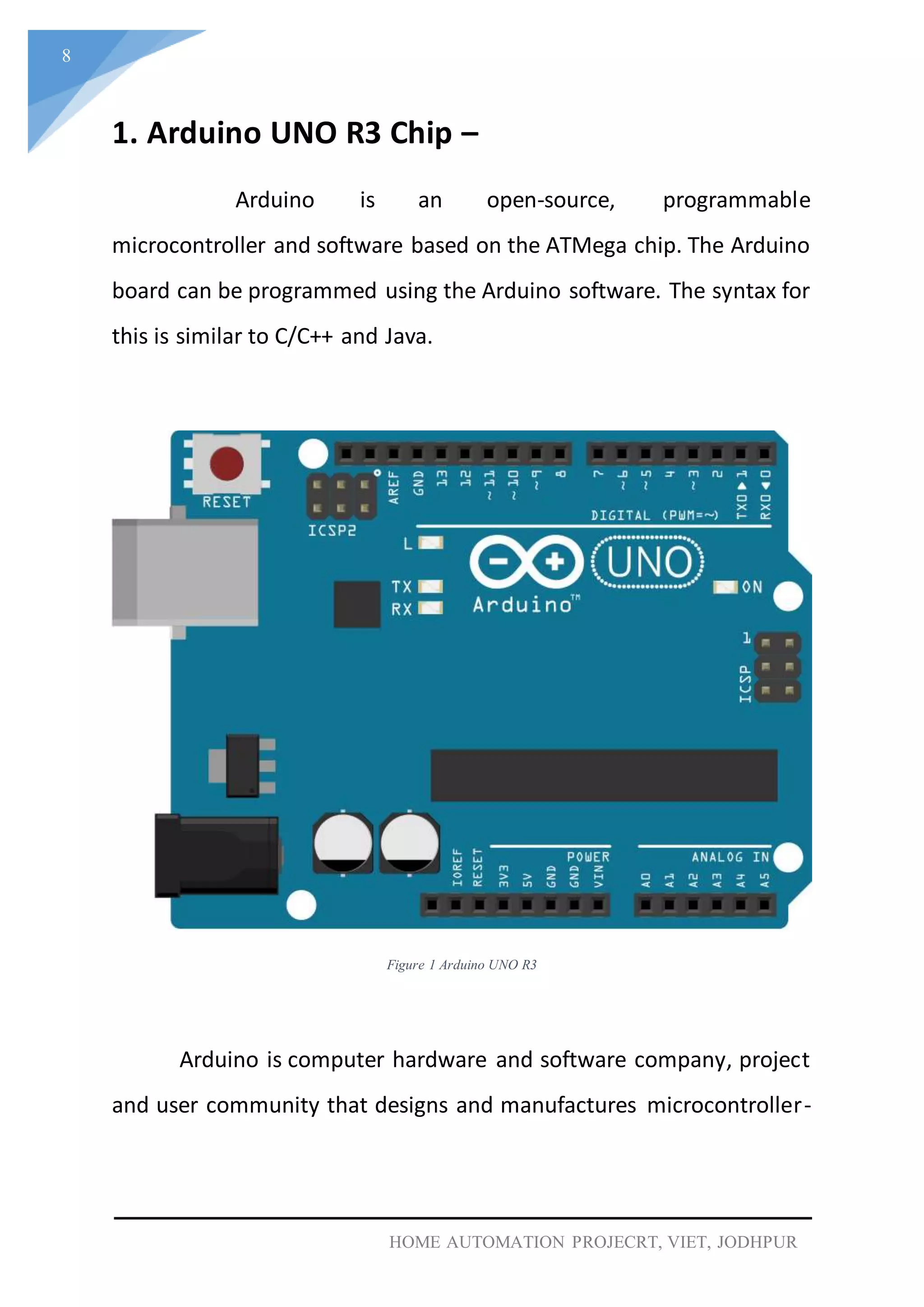
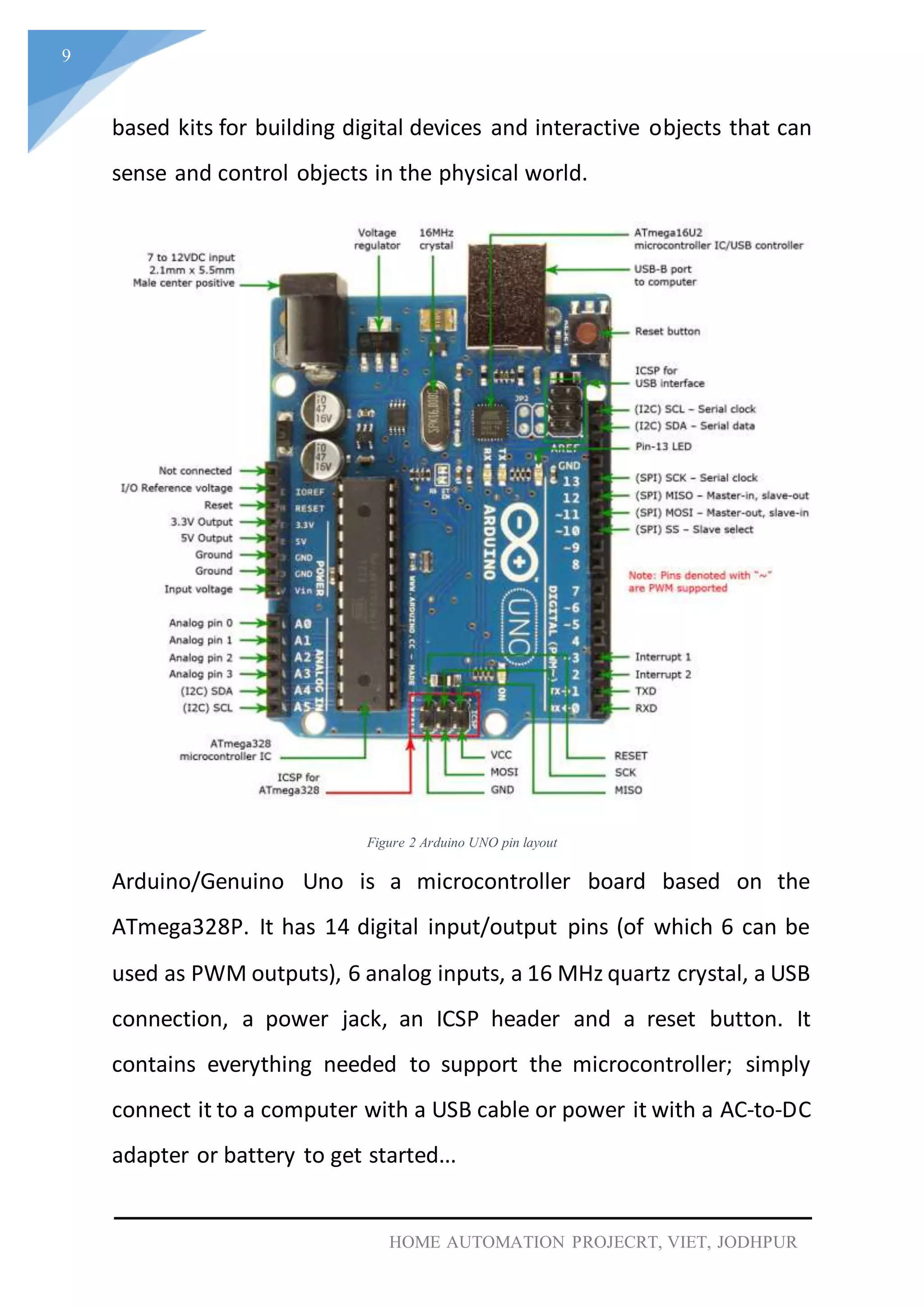
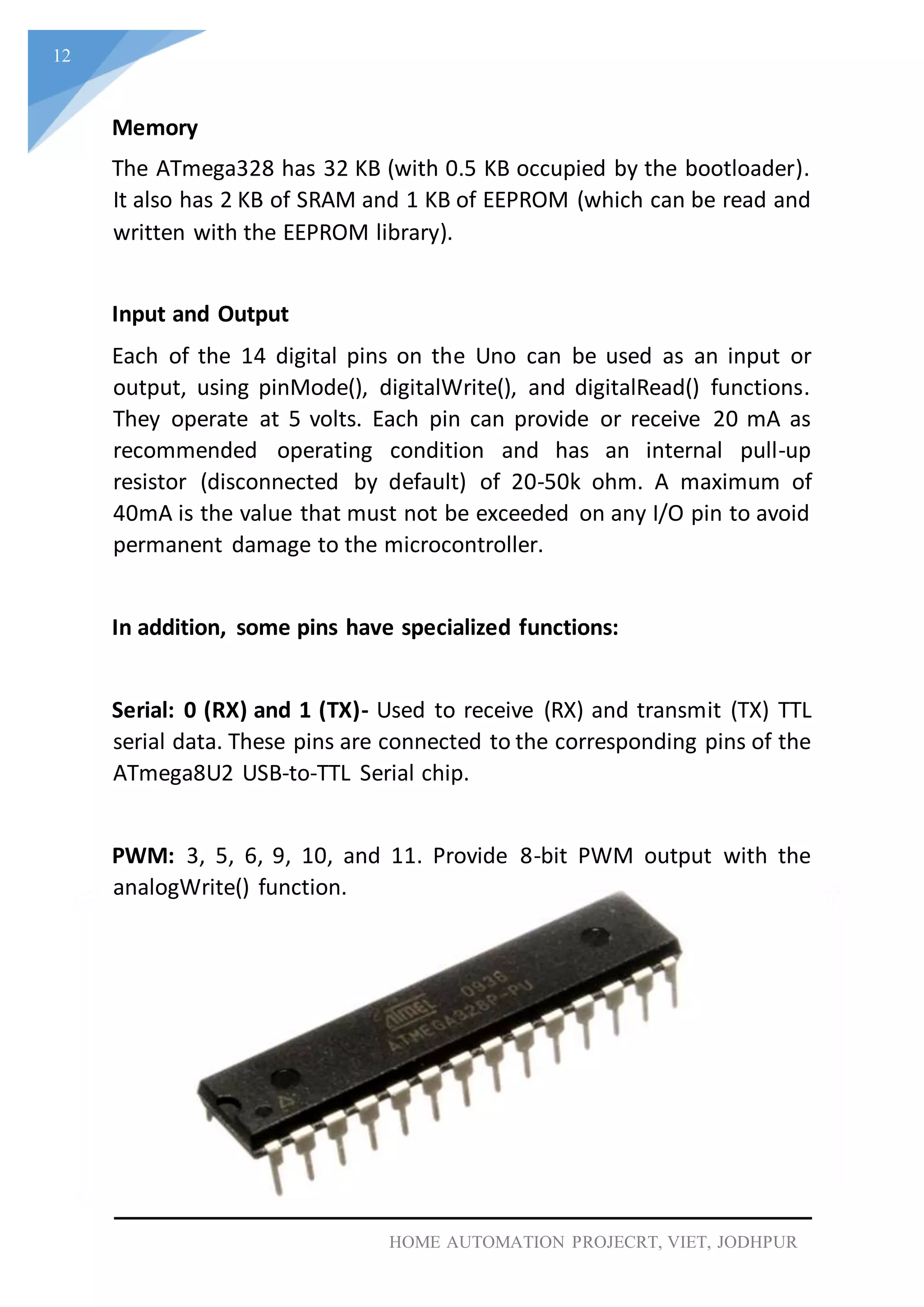
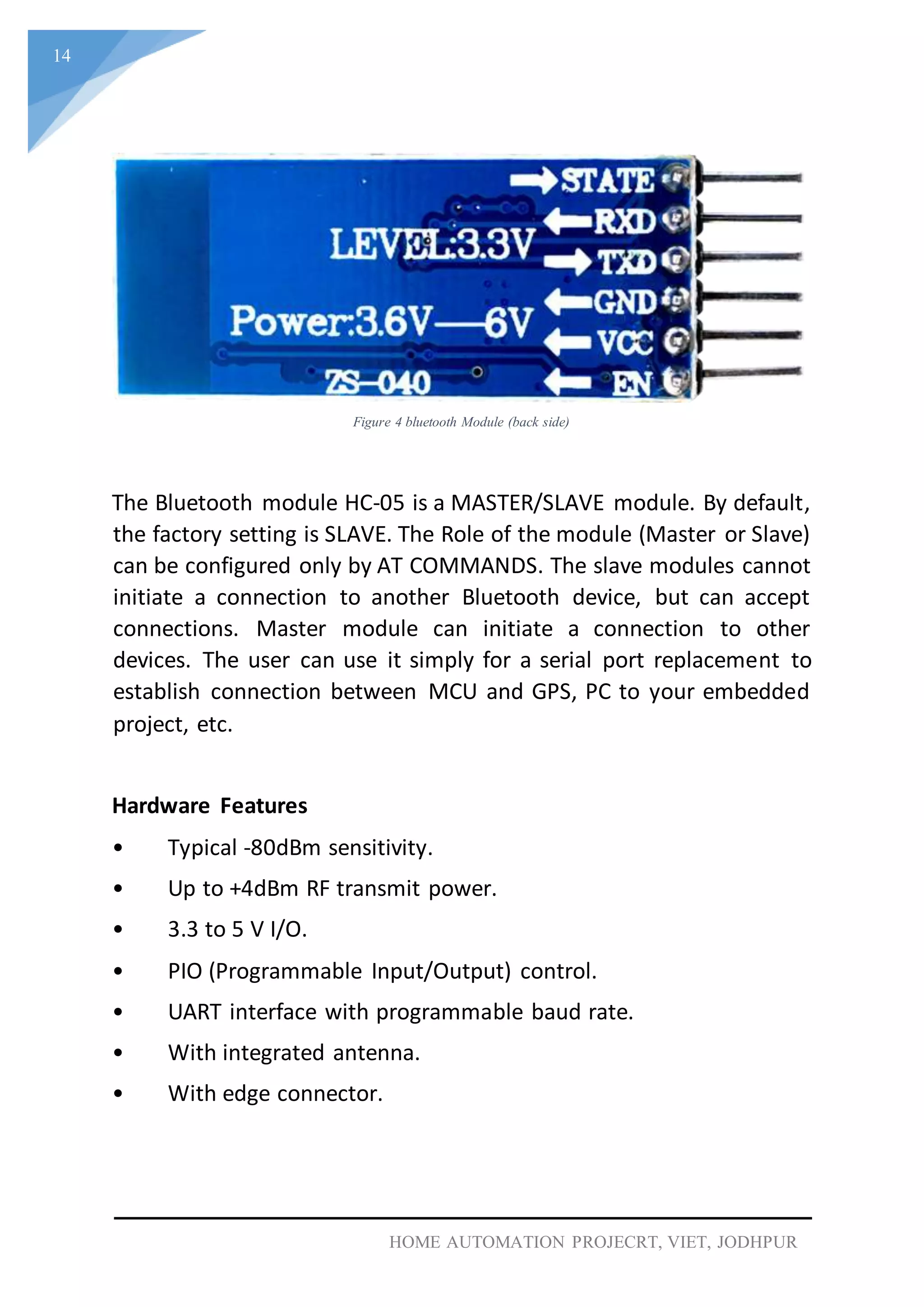
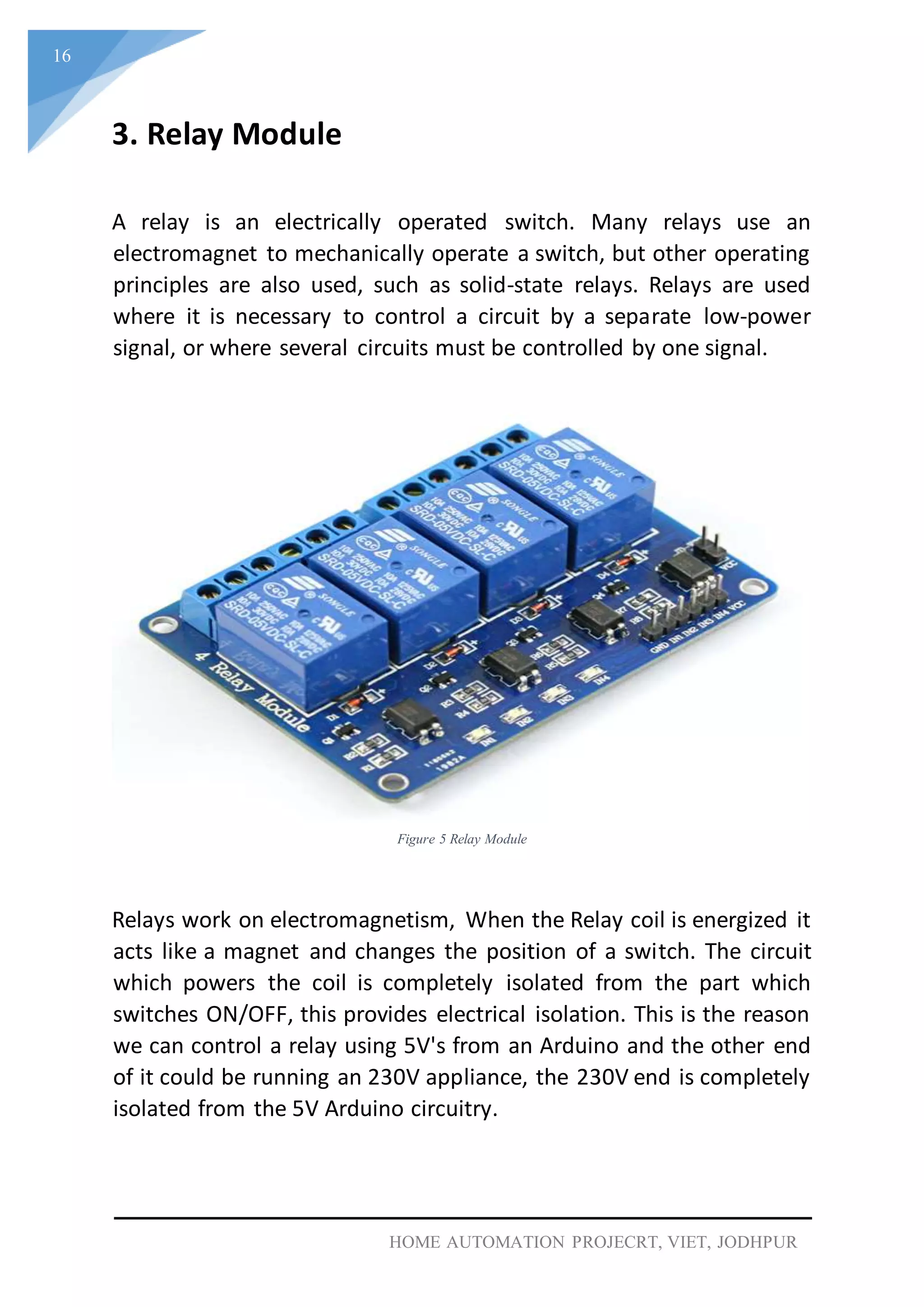
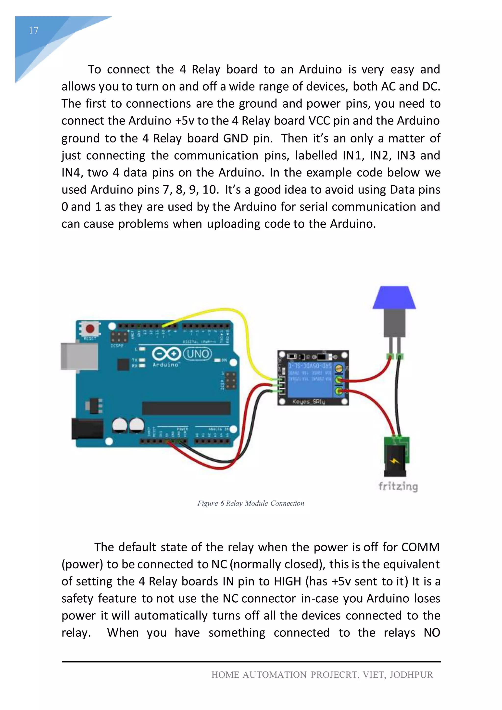
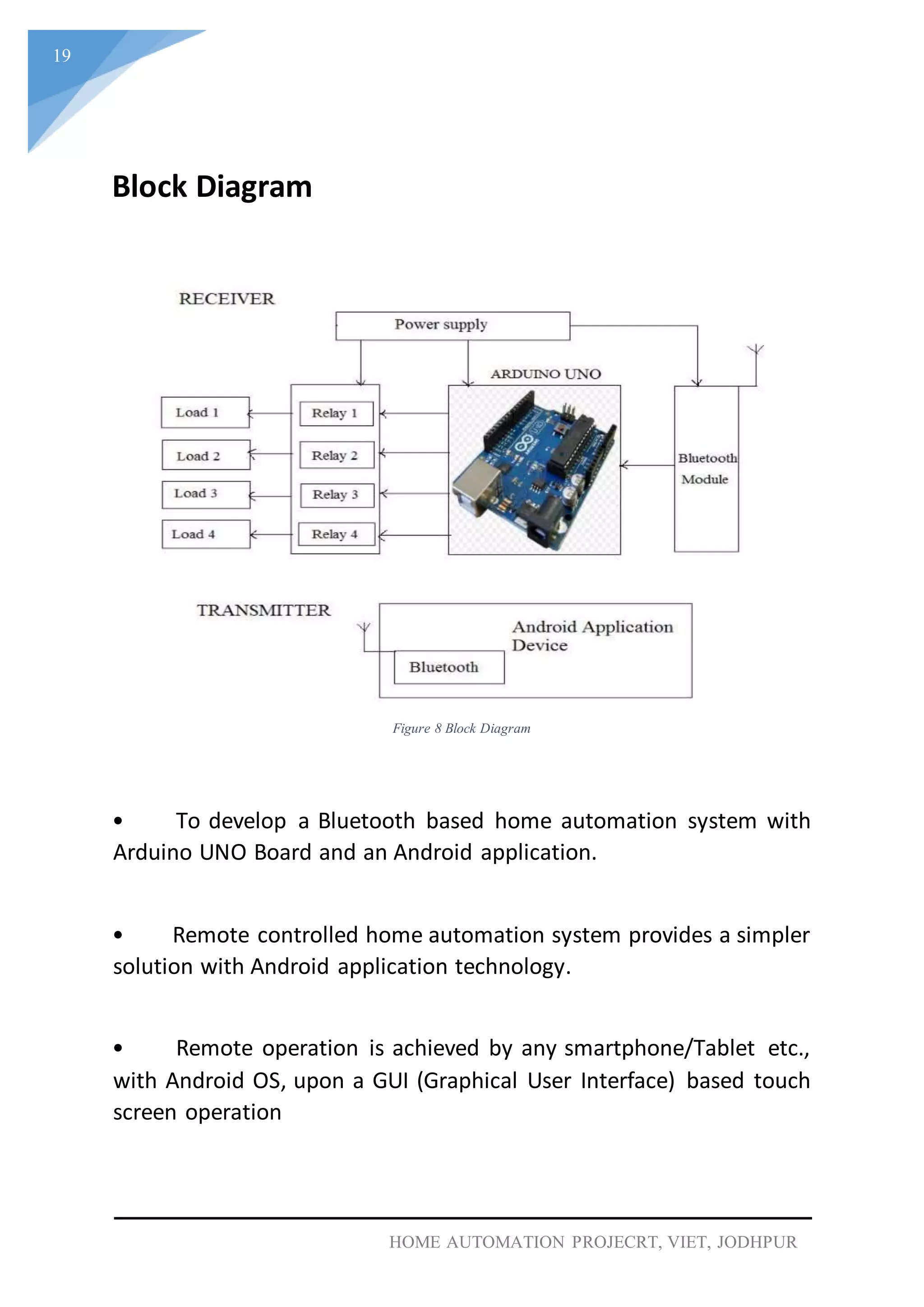
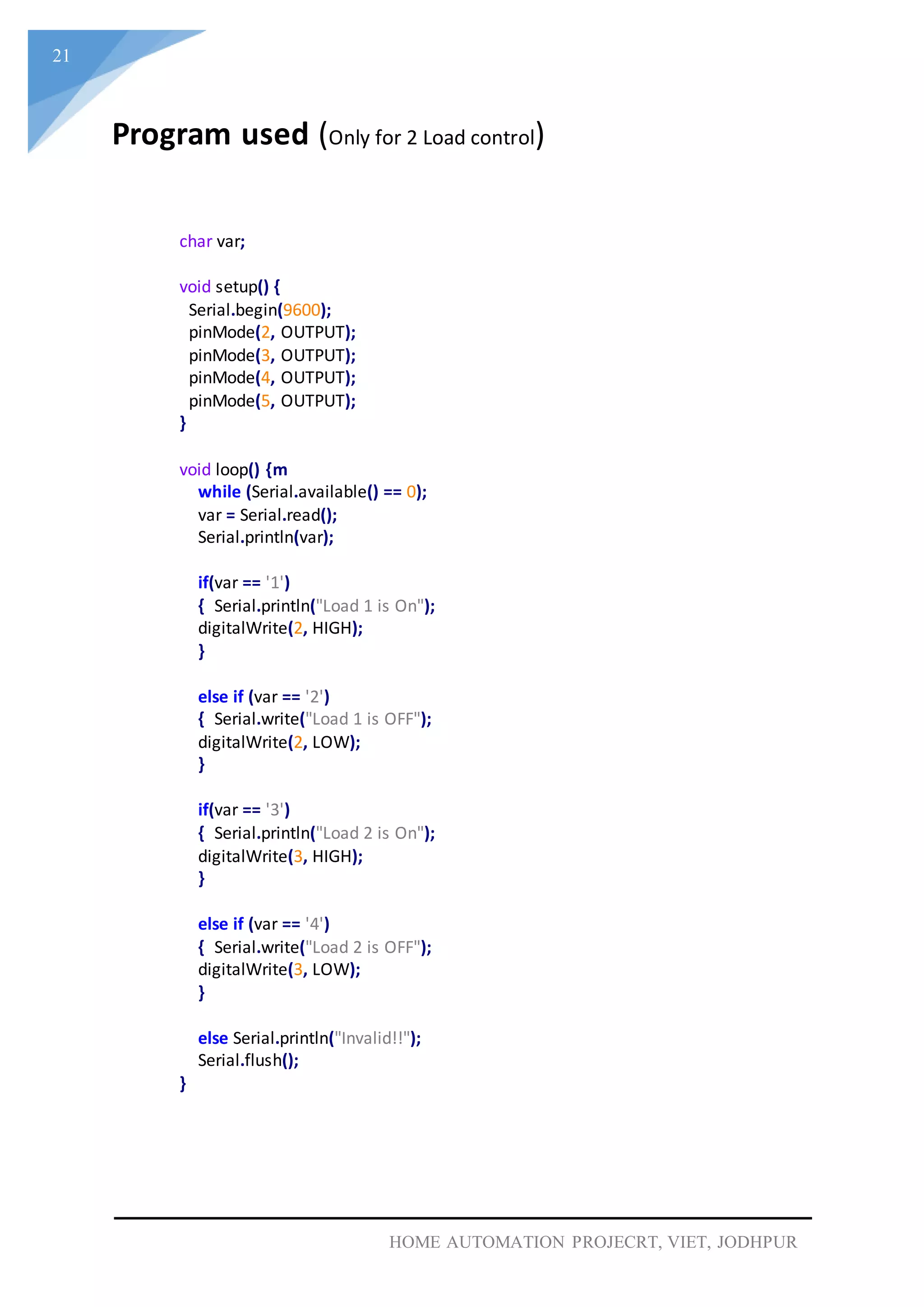
KEMBAR78
Home automation with arduino | DOCX
-
Department of Electrical Engineering
VYAS INSTITUTE OF ENGINEERING AND TECHNOLOGY,
JODHPUR (Raj.)
A
PROJECT REPORT
ON
“Bluetooth based Home
Automation using Arduino”
Submitted in the partial fulfilment for bachelor
of technology degree at
Rajasthan Technical University, Kota
(2016-17)
Submitted to: -
Electrical Branch,
VIET, jodhpur
Submitted by: -
Lakshminarayan,
Mehul Raj,
Pyara Ram,
Jasraj,
Omprakash Meena
1
HOME AUTOMATION PROJECRT, VIET, JODHPUR
VYAS INSTITUTE OF ENGINEERING AND
TECHNOLOGY, JODHPUR (Raj.)
Department of Electrical Engineering
This is to certify that the project entitled, “Bluetooth based Home
Automation using Arduino" submitted by "Lakshminarayan, Mehul Raj,
Jasraj, Pyara Ram, OmprakashMeena" in partial fulfilment of the requirements
for the award of "B. Tech Degree" in "Electrical Engineering" at the "VYAS
INSTITUTE OF ENGINEERING AND TECHNOLOGY, JODHPUR
(Raj.)" is an authentic work carried out by him under my supervision and
guidance.
To the best of my knowledge, the matter embodied in the project has not been
submitted to any other University / Institute for the award of any Degree or
Diploma.
Date:
ProjectGuide Name Submitted to: Head of Department:
Mr. Asad Zai Ansul Bhati Mr. Manish Bhati
CERTIFICATE
2
HOME AUTOMATION PROJECRT, VIET, JODHPUR
TABLE OF CONTENTS
ABSTRACT 3
HOME AUTOMATION 4
NEED OF AUTOMATION 5
INTRODUCTION 6
COMPONENTS USED 7
1. ARDUINO UNO R3 8
2. RC-06 BLUETOOTH MODULE 11
3. RELAY MODULE 16
4. ARDUINO IED SOFTWARE 18
BLOCK DIAGRAM 19
CIRCUIT DIAGRAM 20
PROGRAM USED 21
ADVANTAGES 22
DISADVANTAGES 22
APPLICATION 23
REFERENCES 24
3
HOME AUTOMATION PROJECRT, VIET, JODHPUR
I. ABSTRACT
With advancement of technology things are becoming simpler and
easier for us. Automation is the use of control systems and
information technologies to reduce the need for human work in the
production of goods and services. In the scope of industrialization,
automation is a step beyond mechanization. Whereas mechanization
provided human operators with machinery to assist them with the
muscular requirements of work, automation greatly decreases the
need for human sensory and mental requirements as well.
Automation plays an increasingly important role in the world
economy and in daily experience. Automatic systems are being
preferred over manual system. Through this project we have tried to
show automatic control of a house as a result of which power is saved
to some extent.
The past decade has seen significant advancement in the field of
consumer electronics. Various “intelligent” appliances such as cellular
phone, air conditioners, home security devices, home theatres, etc.,
are set to realize the concept of a smart home. They have given rise
to a Personal Area Network in home environment, where all these
appliances can be interconnected and monitored using a single
controller.
Home automation involves introducing a degree of computerized or
automatic control to certain electrical and electronic systems in a
building. These include lighting, temperature control, etc.
This project demonstrates a simple home automation system which
contains a remote mobile host controller and several client modules
(home appliances). The client modules communicate with the host
controller through a wireless device such as a Bluetooth enabled
mobile phone, in this case, an android based Smart phone.
4
HOME AUTOMATION PROJECRT, VIET, JODHPUR
II. HOME AUTOMATION
Home/office automationis the controlofanyorall electricaldevices
in our home or office, whether we are there or away. Home/office
automationis one ofthe most excitingdevelopments in technologyforthe
home that has come along in decades. There are hundreds of products
available todaythat allowus control overthe devices automatically,either
by remote control; or even by voice command.
Home automation(also called demotics)is the residential extension
of "building automation". It is automation of the home, housework or
household activity. Home automation may include centralized control of
lighting, HVAC (heating, ventilation and air conditioning), appliances, and
other systems, to provide improved convenience, comfort, energy
efficiency and security. Disabled can provide increased quality of life for
persons who might otherwise require caregivers or institutional care.
A home automation system integrates electrical devices in a house
with each other. The techniques employed in home automation include
those in building automation as well as the control of domestic activities,
such as home entertainment systems, houseplant and yard watering, pet
feeding, changing the ambiance "scenes" for different events (such as
dinners or parties), and the use of domestic robots. Devices may be
connected through a computer network to allow control by a personal
computer, and may allow remote access from the internet.
Typically, a new home is outfitted for home automation during
construction, due to the accessibility of the walls, outlets, and storage
rooms,and the abilityto make designchanges specificallyto accommodate
certain technologies. Wireless systems are commonly installed when
outfitting a pre-existing house, as they reduce wiring changes. These
communicate through the existingpower wiring, radio,or infrared signals
with a central controller.Network sockets may be installed in every room
like AC power receptacles.
5
HOME AUTOMATION PROJECRT, VIET, JODHPUR
III. NEED OF AUTOMATION
Earlier, we looked into the face of future when we talked about
automated devices, which could do anything on instigation of a
controller, but today it has become a reality.
a) An automated device can replace good amount of human
working force, moreover humans are more prone to errors
and in intensive conditions the probability of error increases
whereas, an automated device can work with diligence,
versatility and with almost zero error.
 Replacing human operators in tasks that involve hard
physical or monotonous work.
 Replacing humans in tasks done in dangerous
environments (i.e. fire, space, volcanoes, nuclear
facilities, underwater, etc.)
 Performing tasks that are beyond human capabilities of
size, weight, speed, endurance, etc.
 Economy improvement. Automation may improve in
economy of enterprises, society or most of humankind.
For example, when an enterprise that has invested in
automation technology recovers its investment, or
when a state or country increases its income due to
automation like Germany or Japan in the 20th Century.
b) This is why this project looks into construction and
implementation of a system involving hardware to control a
variety of electrical and electronics system.
6
HOME AUTOMATION PROJECRT, VIET, JODHPUR
Introduction
Homes of the 21st century will become more and more self-
controlled and automated. Simple devices such as a timer to turn on
one’s coffee maker in the morning have been around for many years,
but much more sophisticated mechanisms will soon be prevalent in
homes around the world.
Imagine walking into your home and being greeted at the door
with lights illuminating your path without you ever having to touch
light switch, with your favourite music streaming through the
speakers in whichever room you enter (because your home
recognized that it was you and not some other household member),
all while having the peace of mind knowing that your home
automation system took care of activating your security system.
Furthermore, such a system could allow the user to schedule events
to occur at recurring intervals (e.g., turn on sprinkler system at
4:30a.m. every Tuesday and Thursday).
This report describes an approximation of such a home
automation system that was designed and built as a final project for
6.111 at M.I.T. This system was designed to be flexible and generally
programmable, extensible such that adding additional features is
relatively simple, and modular and forward-compatible, so that new
components can be added without redesigning the entire system. To
achieve these goals, the system runs a user-defined program on a
special-purpose processor, using real-world sensor inputs as
operands.
7
HOME AUTOMATION PROJECRT, VIET, JODHPUR
COMPONENTS USED
Following components are used in this project:
1. Hardware
a) Arduino UNO R3
b) Relays Module
c) Bluetooth Module HC-05
d) Android Smart phone
e) Computer
f) Bulbs (15 - 100 watt)
g) Butten Holder
h) Battery with Connector (9V)
i) Plywood Board
j) Connection wires
k) Jumper wires
2. Software
a) Arduino IED (windows)
b) Smart Home (android)
8
HOME AUTOMATION PROJECRT, VIET, JODHPUR
1. Arduino UNO R3 Chip –
Arduino is an open-source, programmable
microcontroller and software based on the ATMega chip. The Arduino
board can be programmed using the Arduino software. The syntax for
this is similar to C/C++ and Java.
Figure 1 Arduino UNO R3
Arduino is computer hardware and software company, project
and user community that designs and manufactures microcontroller-
9
HOME AUTOMATION PROJECRT, VIET, JODHPUR
based kits for building digital devices and interactive objects that can
sense and control objects in the physical world.
Figure 2 Arduino UNO pin layout
Arduino/Genuino Uno is a microcontroller board based on the
ATmega328P. It has 14 digital input/output pins (of which 6 can be
used as PWM outputs), 6 analog inputs, a 16 MHz quartz crystal, a USB
connection, a power jack, an ICSP header and a reset button. It
contains everything needed to support the microcontroller; simply
connect it to a computer with a USB cable or power it with a AC-to-DC
adapter or battery to get started...
10
HOME AUTOMATION PROJECRT, VIET, JODHPUR
Technical specs
Microcontroller ATmega328P
Operating Voltage 5V
Input Voltage (recommended) 7-12V
Input Voltage (limit) 6-20V
Digital I/O Pins 14 (of which 6 provide PWM output)
PWM Digital I/O Pins 6
Analog Input Pins 6
DC Current per I/O Pin 20 mA
DC Current for 3.3V Pin 50 mA
Flash Memory
32 KB (ATmega328P)
of which 0.5 KB used by bootloader
SRAM 2 KB (ATmega328P)
EEPROM 1 KB (ATmega328P)
Clock Speed 16 MHz
LED_BUILTIN 13
Length 68.6 mm
Width 53.4 mm
Weight 25 g
The Arduino/Genuino Uno board can be powered via the USB
connection or with an external power supply. The power source is
selected automatically.
External (non-USB) power can come either from an AC-to-DC adapter
(wall-wart) or battery. The adapter can be connected by plugging a
2.1mm center-positive plug into the board's power jack. Leads from a
battery can be inserted in the GND and Vin pin headers of the POWER
connector.
The board can operate on an external supply from 6 to 20 volts. If
supplied with less than 7V, however, the 5V pin may supply less than
five volts and the board may become unstable. If using more than 12V,
11
HOME AUTOMATION PROJECRT, VIET, JODHPUR
the voltage regulator may overheat and damage the board. The
recommended range is 7 to 12 volts.
The power pins are as follows:
Vin - The input voltage to the Arduino/Genuino board when it's using
an external power source (as opposed to 5 volts from the USB
connection or other regulated power source). You can supply voltage
through this pin, or, if supplying voltage via the power jack, access it
through this pin.
5V - This pin outputs a regulated 5V from the regulator on the board.
The board can be supplied with power either from the DC power jack
(7 - 12V), the USB connector (5V), or the VIN pin of the board (7-12V).
Supplying voltage via the 5V or 3.3V pins bypasses the regulator, and
can damage your board. We don't advise it.
3V3 - A 3.3-volt supply generated by the on-board regulator.
Maximum current draw is 50 mA.
GND - Ground pins.
IOREF - This pin on the Arduino/Genuino board provides the voltage
reference with which the microcontroller operates. A properly
configured shield can read the IOREF pin voltage and select the
appropriate power source or enable voltage translators on the
outputs to work with the 5V or 3.3V.
12
HOME AUTOMATION PROJECRT, VIET, JODHPUR
Memory
The ATmega328 has 32 KB (with 0.5 KB occupied by the bootloader).
It also has 2 KB of SRAM and 1 KB of EEPROM (which can be read and
written with the EEPROM library).
Input and Output
Each of the 14 digital pins on the Uno can be used as an input or
output, using pinMode(), digitalWrite(), and digitalRead() functions.
They operate at 5 volts. Each pin can provide or receive 20 mA as
recommended operating condition and has an internal pull-up
resistor (disconnected by default) of 20-50k ohm. A maximum of
40mA is the value that must not be exceeded on any I/O pin to avoid
permanent damage to the microcontroller.
In addition, some pins have specialized functions:
Serial: 0 (RX) and 1 (TX)- Used to receive (RX) and transmit (TX) TTL
serial data. These pins are connected to the corresponding pins of the
ATmega8U2 USB-to-TTL Serial chip.
PWM: 3, 5, 6, 9, 10, and 11. Provide 8-bit PWM output with the
analogWrite() function.
13
HOME AUTOMATION PROJECRT, VIET, JODHPUR
2. RC – 05 Bluetooth module -
RC – 05 is a Bluetooth module, which is used for create a
connection between two Bluetooth devices, it gets supplied from the
Arduino chip and also give instruction to Arduino chip.
Figure 3 Bluetooth Module (front side)
HC-05 module is an easy to use Bluetooth SPP (Serial Port Protocol)
module, designed for transparent wireless serial connection setup.
The HC-05 Bluetooth Module can be used in a Master or Slave
configuration, making it a great solution for wireless communication.
This serial port Bluetooth module is fully qualified Bluetooth
V2.0+EDR (Enhanced Data Rate) 3Mbps Modulation with complete
2.4GHz radio transceiver and baseband. It uses CSR Blue core 04-
External single chip Bluetooth system with CMOS technology and with
AFH (Adaptive Frequency Hopping Feature).
14
HOME AUTOMATION PROJECRT, VIET, JODHPUR
Figure 4 bluetooth Module (back side)
The Bluetooth module HC-05 is a MASTER/SLAVE module. By default,
the factory setting is SLAVE. The Role of the module (Master or Slave)
can be configured only by AT COMMANDS. The slave modules cannot
initiate a connection to another Bluetooth device, but can accept
connections. Master module can initiate a connection to other
devices. The user can use it simply for a serial port replacement to
establish connection between MCU and GPS, PC to your embedded
project, etc.
Hardware Features
• Typical -80dBm sensitivity.
• Up to +4dBm RF transmit power.
• 3.3 to 5 V I/O.
• PIO (Programmable Input/Output) control.
• UART interface with programmable baud rate.
• With integrated antenna.
• With edge connector.
15
HOME AUTOMATION PROJECRT, VIET, JODHPUR
Software Features
• Slave default Baud rate: 9600, Data bits:8, Stop bit:1, Parity: No
parity.
• Auto-connect to the last device on power as default.
• Permit pairing device to connect as default.
• Auto-pairing PINCODE:”1234” as default.
Pin Description
The HC-05 Bluetooth Module has 6pins. They are as follows:
1. ENABLE:
When enable is pulled LOW, the module is disabled which means the
module will not turn on and it fails to communicate. When enable is
left open or connected to 3.3V, the module is enabled i.e. the module
remains on and communication also takes place.
2. Vcc: Supply Voltage 3.3V to 5V
3. GND: Ground pin
4. TXD & RXD:
These two pins acts as an UART interface for communication
5. STATE:
It acts as a status indicator. When the module is not connected to
paired with any other Bluetooth device, signal goes Low. At this low
state, the led flashes continuously which denotes that the module is
not paired with other device. When this module is connected
to/paired with any other Bluetooth device, the signal goes High. At
this high state, the led blinks with a constant delay say for example 2s
delay which indicates that the module is paired.
16
HOME AUTOMATION PROJECRT, VIET, JODHPUR
3. Relay Module
A relay is an electrically operated switch. Many relays use an
electromagnet to mechanically operate a switch, but other operating
principles are also used, such as solid-state relays. Relays are used
where it is necessary to control a circuit by a separate low-power
signal, or where several circuits must be controlled by one signal.
Figure 5 Relay Module
Relays work on electromagnetism, When the Relay coil is energized it
acts like a magnet and changes the position of a switch. The circuit
which powers the coil is completely isolated from the part which
switches ON/OFF, this provides electrical isolation. This is the reason
we can control a relay using 5V's from an Arduino and the other end
of it could be running an 230V appliance, the 230V end is completely
isolated from the 5V Arduino circuitry.
17
HOME AUTOMATION PROJECRT, VIET, JODHPUR
To connect the 4 Relay board to an Arduino is very easy and
allows you to turn on and off a wide range of devices, both AC and DC.
The first to connections are the ground and power pins, you need to
connect the Arduino +5v to the 4 Relay board VCC pin and the Arduino
ground to the 4 Relay board GND pin. Then it’s an only a matter of
just connecting the communication pins, labelled IN1, IN2, IN3 and
IN4, two 4 data pins on the Arduino. In the example code below we
used Arduino pins 7, 8, 9, 10. It’s a good idea to avoid using Data pins
0 and 1 as they are used by the Arduino for serial communication and
can cause problems when uploading code to the Arduino.
Figure 6 Relay Module Connection
The default state of the relay when the power is off for COMM
(power) to be connected to NC (normally closed), this is the equivalent
of setting the 4 Relay boards IN pin to HIGH (has +5v sent to it) It is a
safety feature to not use the NC connector in-case you Arduino loses
power it will automatically turns off all the devices connected to the
relay. When you have something connected to the relays NO
18
HOME AUTOMATION PROJECRT, VIET, JODHPUR
(Normally Open) connector and you set the corresponding IN pin to
LOW (0v), power will flow in from the COMM connector and out of
the NO connector powering your device.
4. Arduino Software IDE
The Arduino/Genuino Uno can be programmed with the (Arduino
Software (IDE).
The open-source Arduino Software (IDE) makes it easy to write code
and upload it to the board. It runs on Windows, Mac OS X, and Linux.
The environment is written in Java and based on Processing and other
open-source software.
This software can be used with any Arduino board.
Figure 7 Arduino IED Software
19
HOME AUTOMATION PROJECRT, VIET, JODHPUR
Block Diagram
Figure 8 Block Diagram
• To develop a Bluetooth based home automation system with
Arduino UNO Board and an Android application.
• Remote controlled home automation system provides a simpler
solution with Android application technology.
• Remote operation is achieved by any smartphone/Tablet etc.,
with Android OS, upon a GUI (Graphical User Interface) based touch
screen operation
20
HOME AUTOMATION PROJECRT, VIET, JODHPUR
Figure 10 Project pitcher
Circuit Diagram
Figure 9 Circuit Diagram
21
HOME AUTOMATION PROJECRT, VIET, JODHPUR
char var;
void setup() {
Serial.begin(9600);
pinMode(2, OUTPUT);
pinMode(3, OUTPUT);
pinMode(4, OUTPUT);
pinMode(5, OUTPUT);
}
void loop() {m
while (Serial.available() == 0);
var = Serial.read();
Serial.println(var);
if(var == '1')
{ Serial.println("Load 1 is On");
digitalWrite(2, HIGH);
}
else if (var == '2')
{ Serial.write("Load 1 is OFF");
digitalWrite(2, LOW);
}
if(var == '3')
{ Serial.println("Load 2 is On");
digitalWrite(3, HIGH);
}
else if (var == '4')
{ Serial.write("Load 2 is OFF");
digitalWrite(3, LOW);
}
else Serial.println("Invalid!!");
Serial.flush();
}
Program used (Only for 2 Load control)
22
HOME AUTOMATION PROJECRT, VIET, JODHPUR
Advantages
a) Bluetooth is used in this home automation system, which have
a range of 10 to 20 meters so the control cannot be achieved
from outside this range.
b) Application is connected after disconnect of the Bluetooth.
c) When the new users want to connect, first download
application software and then configuration must be done.
d) High power consumption because of bluetooth connectivity.
Disadvantages
a) Bluetooth is used in this home automation system, which have
a range of 10 to 20 meters so the control cannot be achieved
from outside this range.
b) Application is connected after disconnect of the Bluetooth.
c) When the new users want to connect, first download
application software and then configuration must be done.
d) High power consumption because of bluetooth connectivity.
23
HOME AUTOMATION PROJECRT, VIET, JODHPUR
APPLICATIONS
The project designed is very practical in nature because everything
can be controlled with the help of just a mobile phone which is
widely available nowadays and also proves to be handy.
Also the project is feasible because the cost of the project is very less
as compared to the expensive Wi-Fi based home control systems
presently available in the market which require an additional cost of
internet services.
24
HOME AUTOMATION PROJECRT, VIET, JODHPUR
References
www.arduino.org
www.google.com
www.diyhacking.com
www.wikipedia.org
www.elementzonline.com
www.androidcontrol.blogspot.com

Home automation with arduino

  • 1.
    - Department of ElectricalEngineering VYAS INSTITUTE OF ENGINEERING AND TECHNOLOGY, JODHPUR (Raj.) A PROJECT REPORT ON “Bluetooth based Home Automation using Arduino” Submitted in the partial fulfilment for bachelor of technology degree at Rajasthan Technical University, Kota (2016-17) Submitted to: - Electrical Branch, VIET, jodhpur Submitted by: - Lakshminarayan, Mehul Raj, Pyara Ram, Jasraj, Omprakash Meena
  • 2.
    1 HOME AUTOMATION PROJECRT,VIET, JODHPUR VYAS INSTITUTE OF ENGINEERING AND TECHNOLOGY, JODHPUR (Raj.) Department of Electrical Engineering This is to certify that the project entitled, “Bluetooth based Home Automation using Arduino" submitted by "Lakshminarayan, Mehul Raj, Jasraj, Pyara Ram, OmprakashMeena" in partial fulfilment of the requirements for the award of "B. Tech Degree" in "Electrical Engineering" at the "VYAS INSTITUTE OF ENGINEERING AND TECHNOLOGY, JODHPUR (Raj.)" is an authentic work carried out by him under my supervision and guidance. To the best of my knowledge, the matter embodied in the project has not been submitted to any other University / Institute for the award of any Degree or Diploma. Date: ProjectGuide Name Submitted to: Head of Department: Mr. Asad Zai Ansul Bhati Mr. Manish Bhati CERTIFICATE
  • 3.
    2 HOME AUTOMATION PROJECRT,VIET, JODHPUR TABLE OF CONTENTS ABSTRACT 3 HOME AUTOMATION 4 NEED OF AUTOMATION 5 INTRODUCTION 6 COMPONENTS USED 7 1. ARDUINO UNO R3 8 2. RC-06 BLUETOOTH MODULE 11 3. RELAY MODULE 16 4. ARDUINO IED SOFTWARE 18 BLOCK DIAGRAM 19 CIRCUIT DIAGRAM 20 PROGRAM USED 21 ADVANTAGES 22 DISADVANTAGES 22 APPLICATION 23 REFERENCES 24
  • 4.
    3 HOME AUTOMATION PROJECRT,VIET, JODHPUR I. ABSTRACT With advancement of technology things are becoming simpler and easier for us. Automation is the use of control systems and information technologies to reduce the need for human work in the production of goods and services. In the scope of industrialization, automation is a step beyond mechanization. Whereas mechanization provided human operators with machinery to assist them with the muscular requirements of work, automation greatly decreases the need for human sensory and mental requirements as well. Automation plays an increasingly important role in the world economy and in daily experience. Automatic systems are being preferred over manual system. Through this project we have tried to show automatic control of a house as a result of which power is saved to some extent. The past decade has seen significant advancement in the field of consumer electronics. Various “intelligent” appliances such as cellular phone, air conditioners, home security devices, home theatres, etc., are set to realize the concept of a smart home. They have given rise to a Personal Area Network in home environment, where all these appliances can be interconnected and monitored using a single controller. Home automation involves introducing a degree of computerized or automatic control to certain electrical and electronic systems in a building. These include lighting, temperature control, etc. This project demonstrates a simple home automation system which contains a remote mobile host controller and several client modules (home appliances). The client modules communicate with the host controller through a wireless device such as a Bluetooth enabled mobile phone, in this case, an android based Smart phone.
  • 5.
    4 HOME AUTOMATION PROJECRT,VIET, JODHPUR II. HOME AUTOMATION Home/office automationis the controlofanyorall electricaldevices in our home or office, whether we are there or away. Home/office automationis one ofthe most excitingdevelopments in technologyforthe home that has come along in decades. There are hundreds of products available todaythat allowus control overthe devices automatically,either by remote control; or even by voice command. Home automation(also called demotics)is the residential extension of "building automation". It is automation of the home, housework or household activity. Home automation may include centralized control of lighting, HVAC (heating, ventilation and air conditioning), appliances, and other systems, to provide improved convenience, comfort, energy efficiency and security. Disabled can provide increased quality of life for persons who might otherwise require caregivers or institutional care. A home automation system integrates electrical devices in a house with each other. The techniques employed in home automation include those in building automation as well as the control of domestic activities, such as home entertainment systems, houseplant and yard watering, pet feeding, changing the ambiance "scenes" for different events (such as dinners or parties), and the use of domestic robots. Devices may be connected through a computer network to allow control by a personal computer, and may allow remote access from the internet. Typically, a new home is outfitted for home automation during construction, due to the accessibility of the walls, outlets, and storage rooms,and the abilityto make designchanges specificallyto accommodate certain technologies. Wireless systems are commonly installed when outfitting a pre-existing house, as they reduce wiring changes. These communicate through the existingpower wiring, radio,or infrared signals with a central controller.Network sockets may be installed in every room like AC power receptacles.
  • 6.
    5 HOME AUTOMATION PROJECRT,VIET, JODHPUR III. NEED OF AUTOMATION Earlier, we looked into the face of future when we talked about automated devices, which could do anything on instigation of a controller, but today it has become a reality. a) An automated device can replace good amount of human working force, moreover humans are more prone to errors and in intensive conditions the probability of error increases whereas, an automated device can work with diligence, versatility and with almost zero error.  Replacing human operators in tasks that involve hard physical or monotonous work.  Replacing humans in tasks done in dangerous environments (i.e. fire, space, volcanoes, nuclear facilities, underwater, etc.)  Performing tasks that are beyond human capabilities of size, weight, speed, endurance, etc.  Economy improvement. Automation may improve in economy of enterprises, society or most of humankind. For example, when an enterprise that has invested in automation technology recovers its investment, or when a state or country increases its income due to automation like Germany or Japan in the 20th Century. b) This is why this project looks into construction and implementation of a system involving hardware to control a variety of electrical and electronics system.
  • 7.
    6 HOME AUTOMATION PROJECRT,VIET, JODHPUR Introduction Homes of the 21st century will become more and more self- controlled and automated. Simple devices such as a timer to turn on one’s coffee maker in the morning have been around for many years, but much more sophisticated mechanisms will soon be prevalent in homes around the world. Imagine walking into your home and being greeted at the door with lights illuminating your path without you ever having to touch light switch, with your favourite music streaming through the speakers in whichever room you enter (because your home recognized that it was you and not some other household member), all while having the peace of mind knowing that your home automation system took care of activating your security system. Furthermore, such a system could allow the user to schedule events to occur at recurring intervals (e.g., turn on sprinkler system at 4:30a.m. every Tuesday and Thursday). This report describes an approximation of such a home automation system that was designed and built as a final project for 6.111 at M.I.T. This system was designed to be flexible and generally programmable, extensible such that adding additional features is relatively simple, and modular and forward-compatible, so that new components can be added without redesigning the entire system. To achieve these goals, the system runs a user-defined program on a special-purpose processor, using real-world sensor inputs as operands.
  • 8.
    7 HOME AUTOMATION PROJECRT,VIET, JODHPUR COMPONENTS USED Following components are used in this project: 1. Hardware a) Arduino UNO R3 b) Relays Module c) Bluetooth Module HC-05 d) Android Smart phone e) Computer f) Bulbs (15 - 100 watt) g) Butten Holder h) Battery with Connector (9V) i) Plywood Board j) Connection wires k) Jumper wires 2. Software a) Arduino IED (windows) b) Smart Home (android)
  • 9.
    8 HOME AUTOMATION PROJECRT,VIET, JODHPUR 1. Arduino UNO R3 Chip – Arduino is an open-source, programmable microcontroller and software based on the ATMega chip. The Arduino board can be programmed using the Arduino software. The syntax for this is similar to C/C++ and Java. Figure 1 Arduino UNO R3 Arduino is computer hardware and software company, project and user community that designs and manufactures microcontroller-
  • 10.
    9 HOME AUTOMATION PROJECRT,VIET, JODHPUR based kits for building digital devices and interactive objects that can sense and control objects in the physical world. Figure 2 Arduino UNO pin layout Arduino/Genuino Uno is a microcontroller board based on the ATmega328P. It has 14 digital input/output pins (of which 6 can be used as PWM outputs), 6 analog inputs, a 16 MHz quartz crystal, a USB connection, a power jack, an ICSP header and a reset button. It contains everything needed to support the microcontroller; simply connect it to a computer with a USB cable or power it with a AC-to-DC adapter or battery to get started...
  • 11.
    10 HOME AUTOMATION PROJECRT,VIET, JODHPUR Technical specs Microcontroller ATmega328P Operating Voltage 5V Input Voltage (recommended) 7-12V Input Voltage (limit) 6-20V Digital I/O Pins 14 (of which 6 provide PWM output) PWM Digital I/O Pins 6 Analog Input Pins 6 DC Current per I/O Pin 20 mA DC Current for 3.3V Pin 50 mA Flash Memory 32 KB (ATmega328P) of which 0.5 KB used by bootloader SRAM 2 KB (ATmega328P) EEPROM 1 KB (ATmega328P) Clock Speed 16 MHz LED_BUILTIN 13 Length 68.6 mm Width 53.4 mm Weight 25 g The Arduino/Genuino Uno board can be powered via the USB connection or with an external power supply. The power source is selected automatically. External (non-USB) power can come either from an AC-to-DC adapter (wall-wart) or battery. The adapter can be connected by plugging a 2.1mm center-positive plug into the board's power jack. Leads from a battery can be inserted in the GND and Vin pin headers of the POWER connector. The board can operate on an external supply from 6 to 20 volts. If supplied with less than 7V, however, the 5V pin may supply less than five volts and the board may become unstable. If using more than 12V,
  • 12.
    11 HOME AUTOMATION PROJECRT,VIET, JODHPUR the voltage regulator may overheat and damage the board. The recommended range is 7 to 12 volts. The power pins are as follows: Vin - The input voltage to the Arduino/Genuino board when it's using an external power source (as opposed to 5 volts from the USB connection or other regulated power source). You can supply voltage through this pin, or, if supplying voltage via the power jack, access it through this pin. 5V - This pin outputs a regulated 5V from the regulator on the board. The board can be supplied with power either from the DC power jack (7 - 12V), the USB connector (5V), or the VIN pin of the board (7-12V). Supplying voltage via the 5V or 3.3V pins bypasses the regulator, and can damage your board. We don't advise it. 3V3 - A 3.3-volt supply generated by the on-board regulator. Maximum current draw is 50 mA. GND - Ground pins. IOREF - This pin on the Arduino/Genuino board provides the voltage reference with which the microcontroller operates. A properly configured shield can read the IOREF pin voltage and select the appropriate power source or enable voltage translators on the outputs to work with the 5V or 3.3V.
  • 13.
    12 HOME AUTOMATION PROJECRT,VIET, JODHPUR Memory The ATmega328 has 32 KB (with 0.5 KB occupied by the bootloader). It also has 2 KB of SRAM and 1 KB of EEPROM (which can be read and written with the EEPROM library). Input and Output Each of the 14 digital pins on the Uno can be used as an input or output, using pinMode(), digitalWrite(), and digitalRead() functions. They operate at 5 volts. Each pin can provide or receive 20 mA as recommended operating condition and has an internal pull-up resistor (disconnected by default) of 20-50k ohm. A maximum of 40mA is the value that must not be exceeded on any I/O pin to avoid permanent damage to the microcontroller. In addition, some pins have specialized functions: Serial: 0 (RX) and 1 (TX)- Used to receive (RX) and transmit (TX) TTL serial data. These pins are connected to the corresponding pins of the ATmega8U2 USB-to-TTL Serial chip. PWM: 3, 5, 6, 9, 10, and 11. Provide 8-bit PWM output with the analogWrite() function.
  • 14.
    13 HOME AUTOMATION PROJECRT,VIET, JODHPUR 2. RC – 05 Bluetooth module - RC – 05 is a Bluetooth module, which is used for create a connection between two Bluetooth devices, it gets supplied from the Arduino chip and also give instruction to Arduino chip. Figure 3 Bluetooth Module (front side) HC-05 module is an easy to use Bluetooth SPP (Serial Port Protocol) module, designed for transparent wireless serial connection setup. The HC-05 Bluetooth Module can be used in a Master or Slave configuration, making it a great solution for wireless communication. This serial port Bluetooth module is fully qualified Bluetooth V2.0+EDR (Enhanced Data Rate) 3Mbps Modulation with complete 2.4GHz radio transceiver and baseband. It uses CSR Blue core 04- External single chip Bluetooth system with CMOS technology and with AFH (Adaptive Frequency Hopping Feature).
  • 15.
    14 HOME AUTOMATION PROJECRT,VIET, JODHPUR Figure 4 bluetooth Module (back side) The Bluetooth module HC-05 is a MASTER/SLAVE module. By default, the factory setting is SLAVE. The Role of the module (Master or Slave) can be configured only by AT COMMANDS. The slave modules cannot initiate a connection to another Bluetooth device, but can accept connections. Master module can initiate a connection to other devices. The user can use it simply for a serial port replacement to establish connection between MCU and GPS, PC to your embedded project, etc. Hardware Features • Typical -80dBm sensitivity. • Up to +4dBm RF transmit power. • 3.3 to 5 V I/O. • PIO (Programmable Input/Output) control. • UART interface with programmable baud rate. • With integrated antenna. • With edge connector.
  • 16.
    15 HOME AUTOMATION PROJECRT,VIET, JODHPUR Software Features • Slave default Baud rate: 9600, Data bits:8, Stop bit:1, Parity: No parity. • Auto-connect to the last device on power as default. • Permit pairing device to connect as default. • Auto-pairing PINCODE:”1234” as default. Pin Description The HC-05 Bluetooth Module has 6pins. They are as follows: 1. ENABLE: When enable is pulled LOW, the module is disabled which means the module will not turn on and it fails to communicate. When enable is left open or connected to 3.3V, the module is enabled i.e. the module remains on and communication also takes place. 2. Vcc: Supply Voltage 3.3V to 5V 3. GND: Ground pin 4. TXD & RXD: These two pins acts as an UART interface for communication 5. STATE: It acts as a status indicator. When the module is not connected to paired with any other Bluetooth device, signal goes Low. At this low state, the led flashes continuously which denotes that the module is not paired with other device. When this module is connected to/paired with any other Bluetooth device, the signal goes High. At this high state, the led blinks with a constant delay say for example 2s delay which indicates that the module is paired.
  • 17.
    16 HOME AUTOMATION PROJECRT,VIET, JODHPUR 3. Relay Module A relay is an electrically operated switch. Many relays use an electromagnet to mechanically operate a switch, but other operating principles are also used, such as solid-state relays. Relays are used where it is necessary to control a circuit by a separate low-power signal, or where several circuits must be controlled by one signal. Figure 5 Relay Module Relays work on electromagnetism, When the Relay coil is energized it acts like a magnet and changes the position of a switch. The circuit which powers the coil is completely isolated from the part which switches ON/OFF, this provides electrical isolation. This is the reason we can control a relay using 5V's from an Arduino and the other end of it could be running an 230V appliance, the 230V end is completely isolated from the 5V Arduino circuitry.
  • 18.
    17 HOME AUTOMATION PROJECRT,VIET, JODHPUR To connect the 4 Relay board to an Arduino is very easy and allows you to turn on and off a wide range of devices, both AC and DC. The first to connections are the ground and power pins, you need to connect the Arduino +5v to the 4 Relay board VCC pin and the Arduino ground to the 4 Relay board GND pin. Then it’s an only a matter of just connecting the communication pins, labelled IN1, IN2, IN3 and IN4, two 4 data pins on the Arduino. In the example code below we used Arduino pins 7, 8, 9, 10. It’s a good idea to avoid using Data pins 0 and 1 as they are used by the Arduino for serial communication and can cause problems when uploading code to the Arduino. Figure 6 Relay Module Connection The default state of the relay when the power is off for COMM (power) to be connected to NC (normally closed), this is the equivalent of setting the 4 Relay boards IN pin to HIGH (has +5v sent to it) It is a safety feature to not use the NC connector in-case you Arduino loses power it will automatically turns off all the devices connected to the relay. When you have something connected to the relays NO
  • 19.
    18 HOME AUTOMATION PROJECRT,VIET, JODHPUR (Normally Open) connector and you set the corresponding IN pin to LOW (0v), power will flow in from the COMM connector and out of the NO connector powering your device. 4. Arduino Software IDE The Arduino/Genuino Uno can be programmed with the (Arduino Software (IDE). The open-source Arduino Software (IDE) makes it easy to write code and upload it to the board. It runs on Windows, Mac OS X, and Linux. The environment is written in Java and based on Processing and other open-source software. This software can be used with any Arduino board. Figure 7 Arduino IED Software
  • 20.
    19 HOME AUTOMATION PROJECRT,VIET, JODHPUR Block Diagram Figure 8 Block Diagram • To develop a Bluetooth based home automation system with Arduino UNO Board and an Android application. • Remote controlled home automation system provides a simpler solution with Android application technology. • Remote operation is achieved by any smartphone/Tablet etc., with Android OS, upon a GUI (Graphical User Interface) based touch screen operation
  • 21.
    20 HOME AUTOMATION PROJECRT,VIET, JODHPUR Figure 10 Project pitcher Circuit Diagram Figure 9 Circuit Diagram
  • 22.
    21 HOME AUTOMATION PROJECRT,VIET, JODHPUR char var; void setup() { Serial.begin(9600); pinMode(2, OUTPUT); pinMode(3, OUTPUT); pinMode(4, OUTPUT); pinMode(5, OUTPUT); } void loop() {m while (Serial.available() == 0); var = Serial.read(); Serial.println(var); if(var == '1') { Serial.println("Load 1 is On"); digitalWrite(2, HIGH); } else if (var == '2') { Serial.write("Load 1 is OFF"); digitalWrite(2, LOW); } if(var == '3') { Serial.println("Load 2 is On"); digitalWrite(3, HIGH); } else if (var == '4') { Serial.write("Load 2 is OFF"); digitalWrite(3, LOW); } else Serial.println("Invalid!!"); Serial.flush(); } Program used (Only for 2 Load control)
  • 23.
    22 HOME AUTOMATION PROJECRT,VIET, JODHPUR Advantages a) Bluetooth is used in this home automation system, which have a range of 10 to 20 meters so the control cannot be achieved from outside this range. b) Application is connected after disconnect of the Bluetooth. c) When the new users want to connect, first download application software and then configuration must be done. d) High power consumption because of bluetooth connectivity. Disadvantages a) Bluetooth is used in this home automation system, which have a range of 10 to 20 meters so the control cannot be achieved from outside this range. b) Application is connected after disconnect of the Bluetooth. c) When the new users want to connect, first download application software and then configuration must be done. d) High power consumption because of bluetooth connectivity.
  • 24.
    23 HOME AUTOMATION PROJECRT,VIET, JODHPUR APPLICATIONS The project designed is very practical in nature because everything can be controlled with the help of just a mobile phone which is widely available nowadays and also proves to be handy. Also the project is feasible because the cost of the project is very less as compared to the expensive Wi-Fi based home control systems presently available in the market which require an additional cost of internet services.
  • 25.
    24 HOME AUTOMATION PROJECRT,VIET, JODHPUR References www.arduino.org www.google.com www.diyhacking.com www.wikipedia.org www.elementzonline.com www.androidcontrol.blogspot.com