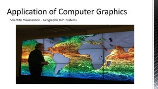
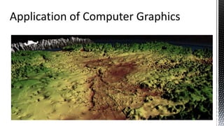
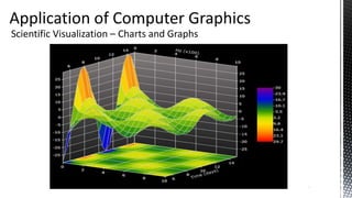
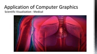
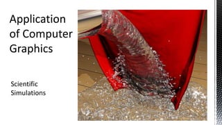
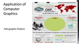
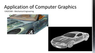
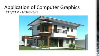
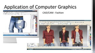
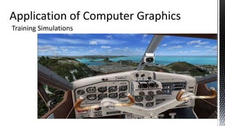
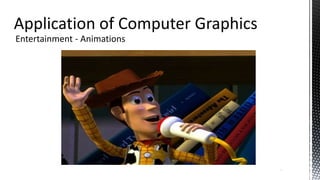
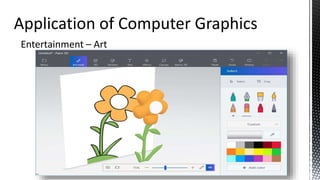
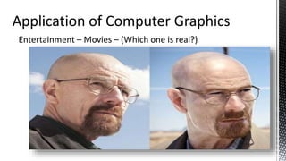
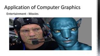
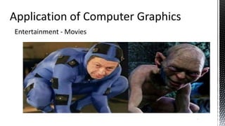
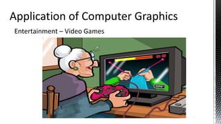
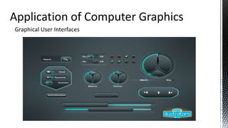
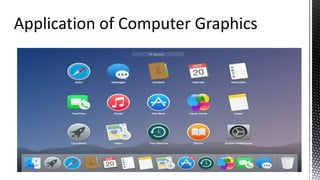
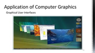
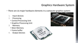
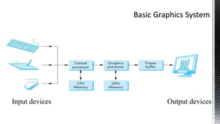
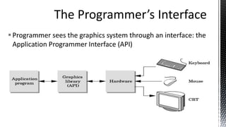
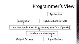
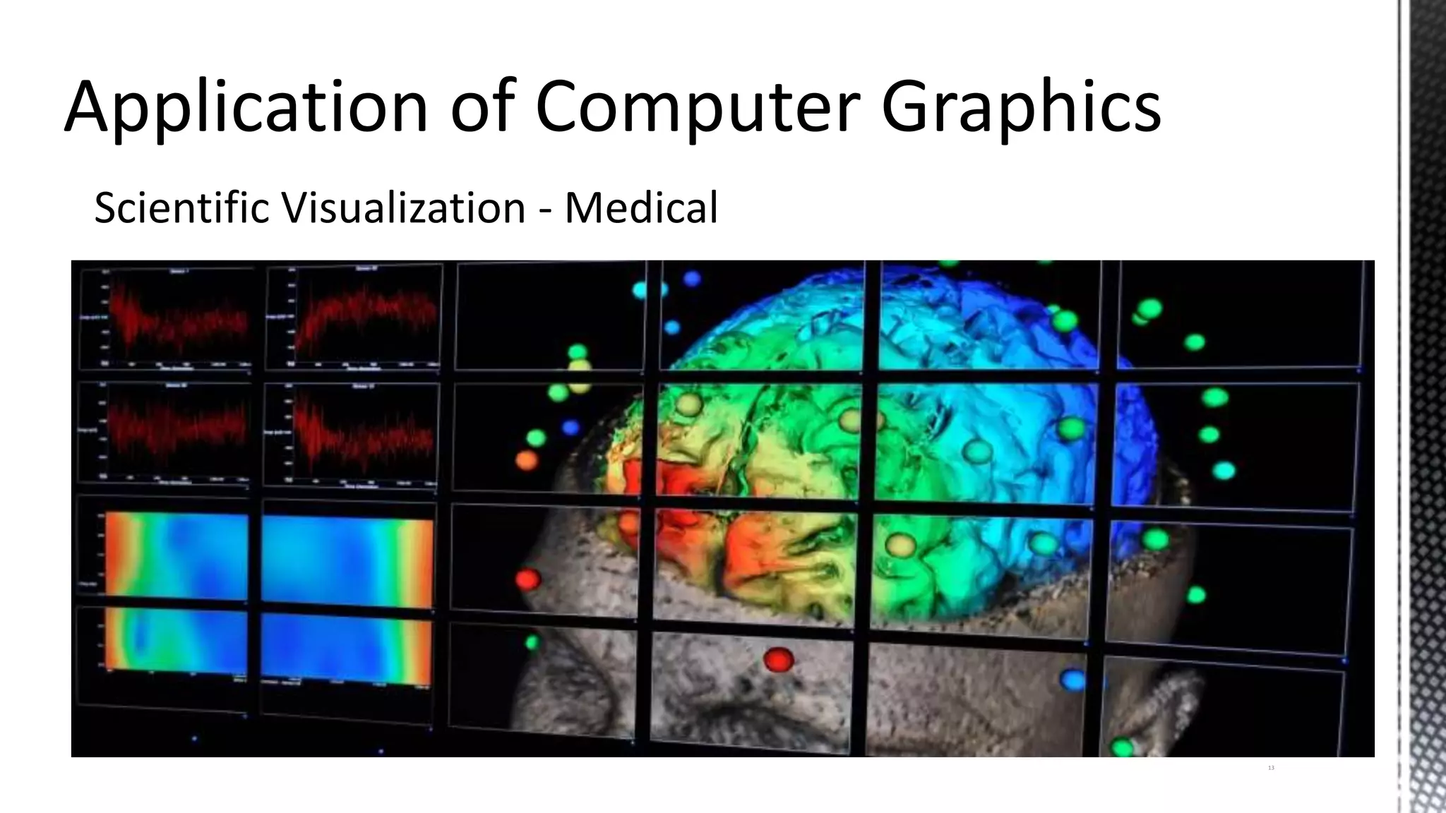
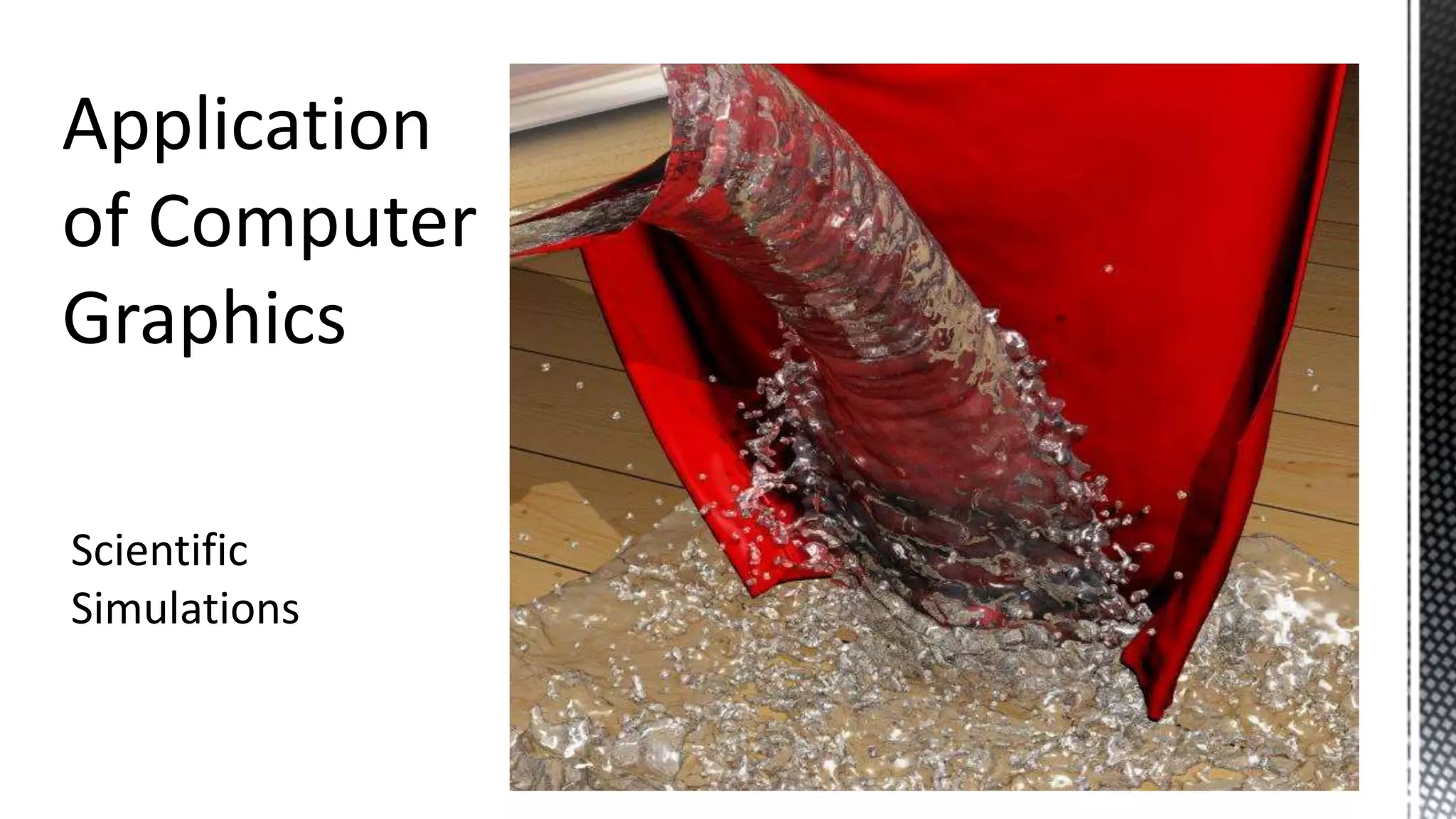
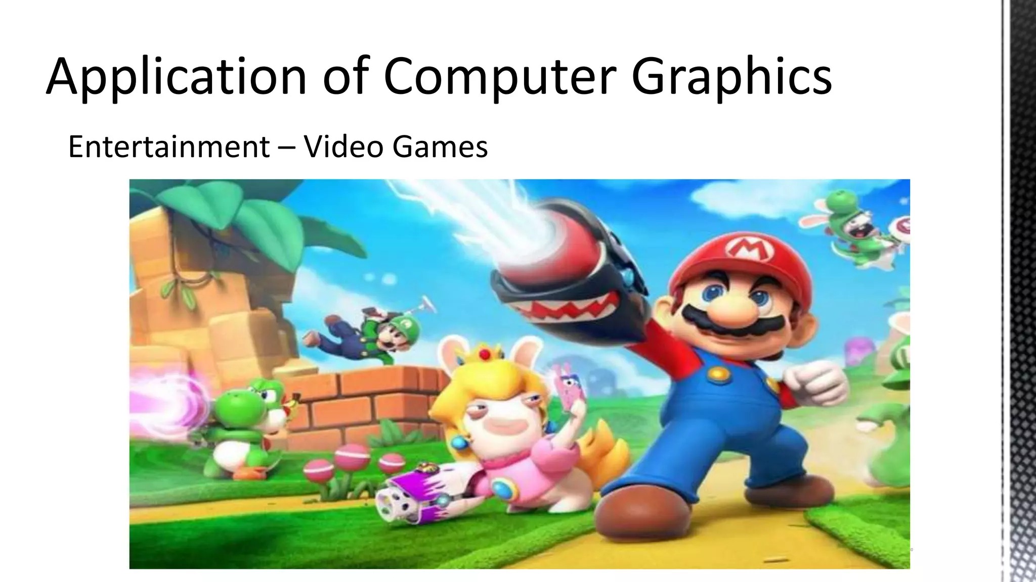
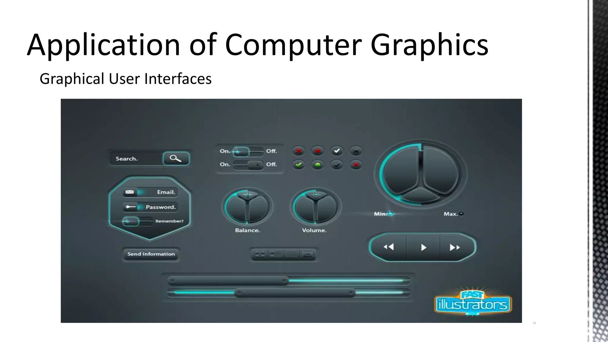
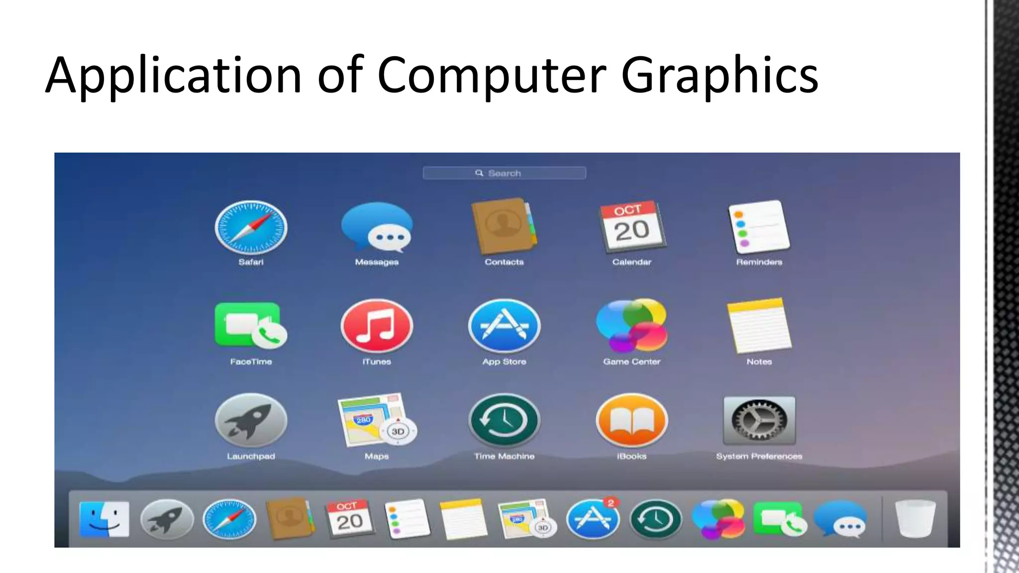
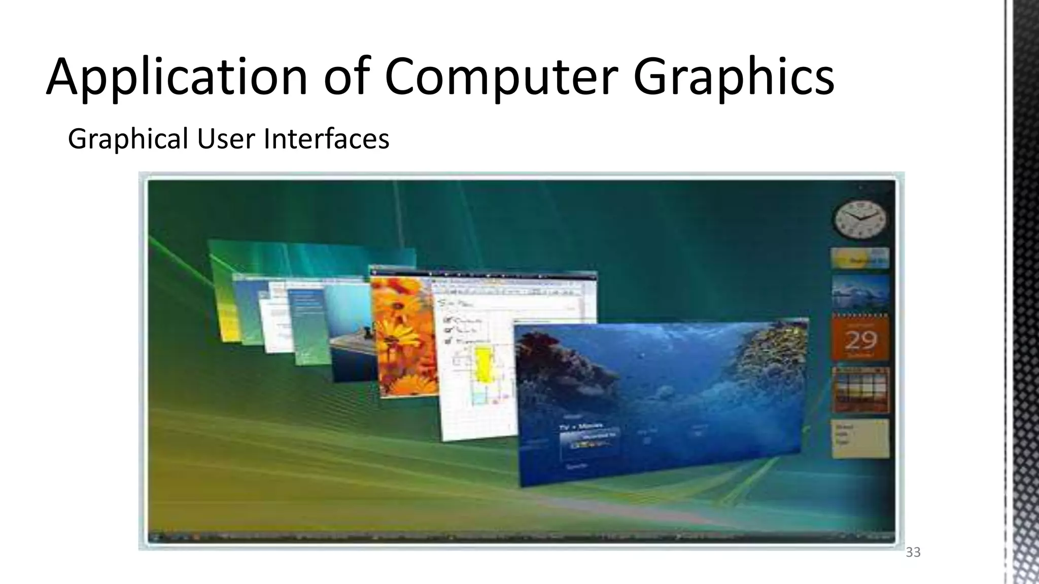
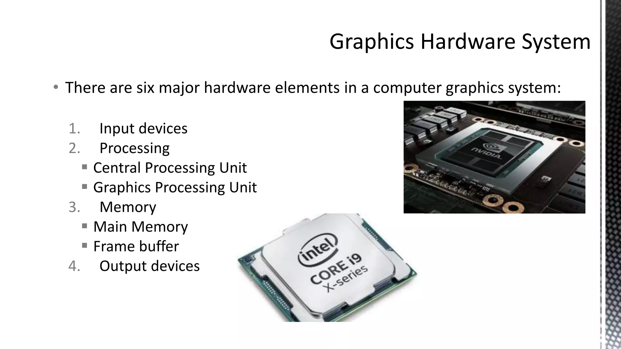
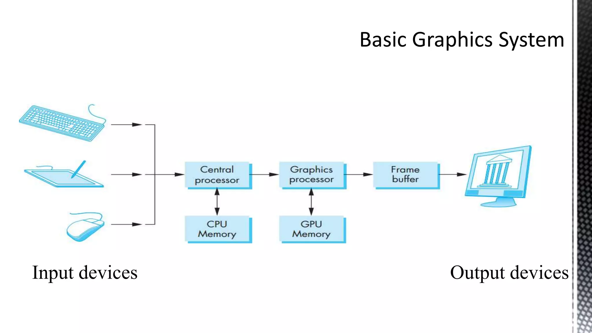
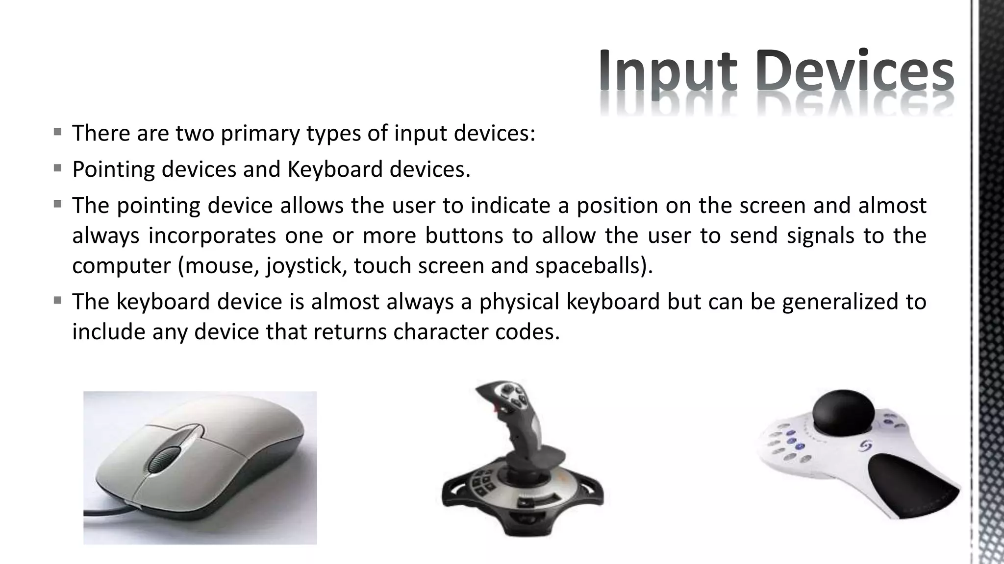
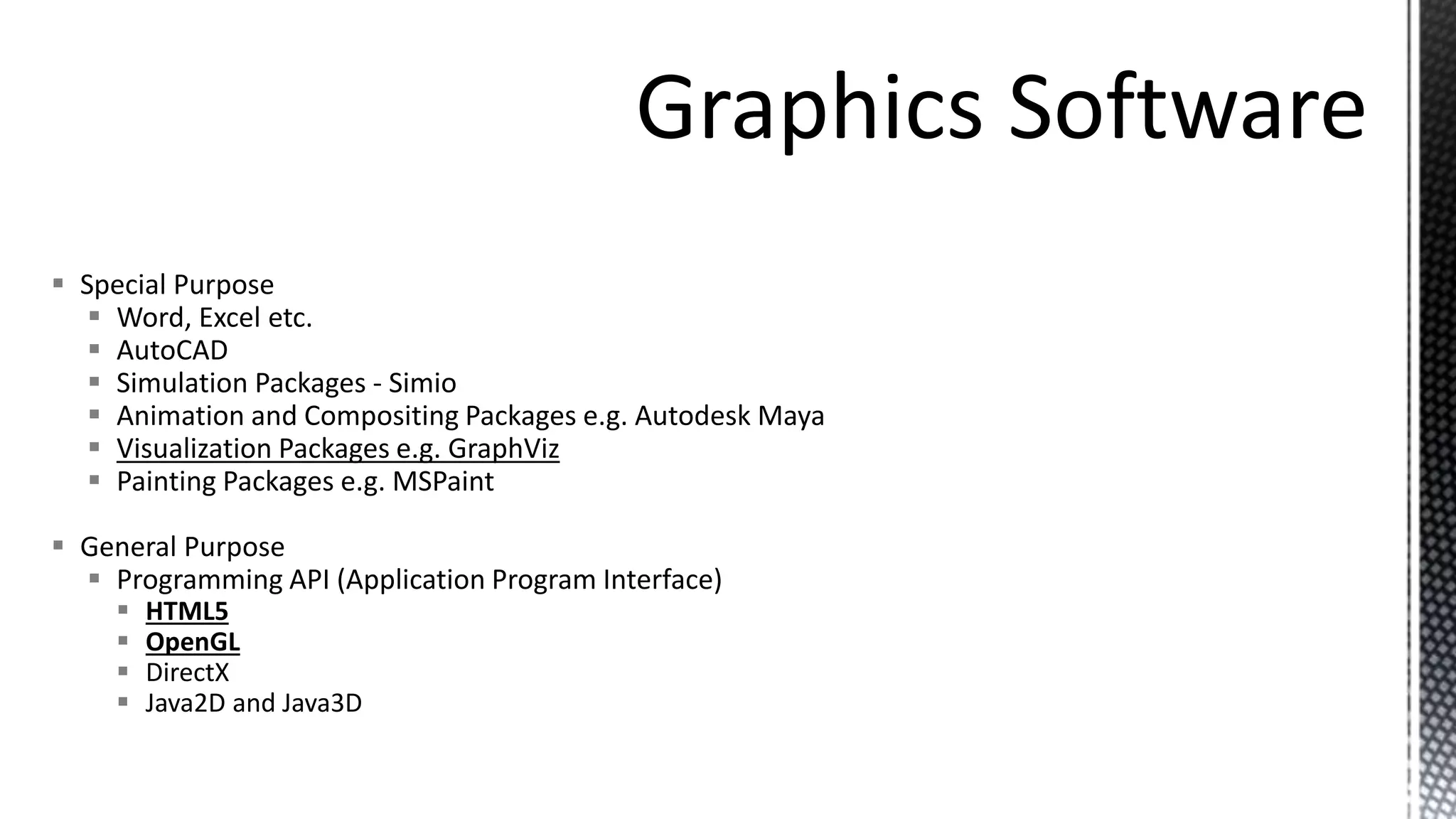
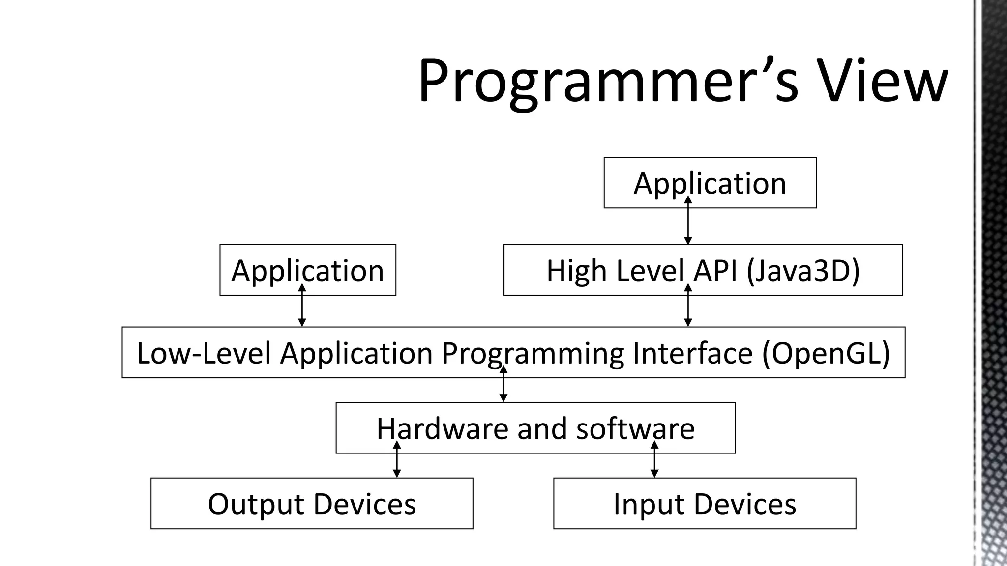
KEMBAR78
Introduction to Computer Graphics.pptx
A. A. Datti 2022
Introduction
Applications of Computer Graphics
Graphics System
2
Computer graphics is the creation and manipulation of geometric
objects (models) and images using computer.
Computer graphics is concerned with all aspects of producing pictures
or images using a computer.
Computer graphics is involved in any work that uses computation to
create or modify images, whether those images are still or moving;
interactive or fixed; on film, video, screen, or print.
3
 The applications of computer graphics are many and varied; we can, however, divide them
into four major areas:
1. Display of information (Graphs, Maps, and Medical images)
2. Design (Engineering etc)
3. Simulation and animation (Training, Games, Movies, Virtual Reality and Scientific
Simulations)
4. User interfaces (Operating systems and application software)
Many applications may span two or more of these areas.
4
Statistics– Charts and Graphs
5
Statistics – Charts and Graphs
6
Scientific Visualization – Charts and Graphs
7
Scientific Visualization – Charts and Graphs
8
Scientific Visualization – Geographic Info. Systems
9
Scientific Visualization – Geographic Info. Systems
10
Scientific Visualization – Charts and Graphs
11
Scientific Visualization - Medical
12
Scientific Visualization - Medical
13
Scientific
Simulations
14
Scientific Simulations
Simulations
Simulations
Info graphic Posters
18
CAD/CAM – Mechanical Engineering
19
20
CAD/CAM - Architecture
21
CAD/CAM - Fashion
Augmented Reality
22
Training Simulations
23
Entertainment - Animations
24
Entertainment – Art
25
Entertainment – Movies – (Which one is real?)
26
Entertainment - Movies
27
Entertainment - Movies
28
Entertainment – Video Games
29
Entertainment – Video Games
30
Graphical User Interfaces
31
Graphical User Interfaces
32
Graphical User Interfaces
33
Introduction
Applications of Computer Graphics
Graphics System
Hardware
Software
34
• There are six major hardware elements in a computer graphics system:
1. Input devices
2. Processing
 Central Processing Unit
 Graphics Processing Unit
3. Memory
 Main Memory
 Frame buffer
4. Output devices
Input devices Output devices
• There are ways images are represented on digital output devices
Raster and Vector.
• Virtually all modern graphics systems are raster based. The image
we see on the output device is an array—the raster—of picture
elements, or pixels, produced by the graphics system.
Vector Systems on the
other hand represent
an image as collection
of lines.
*Each pixel corresponds to a location, or small area, in the image.
*Collectively, the pixels are sored in a part of memory called the
frame buffer.
*The frame buffer can be viewed as the core element of a graphics
system.
*Its resolution - the number of pixels in the frame buffer - determines
the detail that you can see in the image. E.g. 1024 * 768 (=786,432
pixels)
*The depth or precision of the frame buffer, defined as the number of
bits that are used for each pixel, determines properties such as how
many colors can be represented on a given system.
*For example, a 1-bit-deep frame buffer allows only 2 colors (21),
whereas an 8-bit-deep frame buffer allows 256 colors (28).
*In full-color systems, there are 24 (or more) bits per pixel. Such
systems can display sufficient colors to represent most images
realistically. They are also called true-color systems, or RGB-color
systems, because individual groups of bits in each pixel are assigned to
each of the three primary colors—red, green, and blue—used in most
displays.
1 bit (2 colors) 2 bit (4 colors) 4 bit (16 colors)
8 bits (256 colors) 24 bits (16,777,216 colors) 32 bits (4,294,967,296 colors)
*In a simple system, there may be only one processor, the central processing
unit (CPU) of the system, which must do both the normal processing and the
graphical processing.
*The main graphical function of the processor is to take specifications of
graphical primitives (such as lines, circles, and polygons) generated by
application programs and to assign values to the pixels in the frame buffer that
best represent these entities.
*For example, a triangle is specified by its three vertices, the graphics system
must generate a set of pixels that appear as line segments to the viewer. The
conversion of geometric entities to pixel colors and locations in the frame buffer
is known as rasterization, or scan conversion.
*Graphics Processing Units (on modern systems) on the other hand are
dedicated processing units specialized in (the above) graphic functions.
Hardcopy
•Dot Matrix Printers
•Ink-Jet Printers
•Laser Printers
•3D Printers
Softcopy
•Cathode Ray Tube (CRT)
•Liquid Crystal Display (LCD)
Miscellaneous
•Hologram
• Dot Matrix - uses a head with 7 to 24 pins to strike a ribbon
(single or multiple color)
• Ink Jet Printers: a printer in which the characters are formed
by minute jets of ink. (fires small balls of colored ink)
• Laser Printers: a printer linked to a computer producing
printed material by using a laser to form a pattern of
electrostatically charged dots on a light-sensitive drum,
which attract toner (or dry ink powder). The toner is
transferred to a piece of paper and fixed by a heating
process.
•3D Printers: a machine allowing the creation of a physical
object from a three-dimensional digital model, typically by
laying down many thin layers of a material in succession.
• In a raster system, the graphics system takes pixels
from the frame buffer and
displays them as points on the surface of the display.
• Examples
• Cathode Ray Tube (CRT)
• Liquid Crystal Display (LCD)
• Light Emitting Diode (LED) Display
 When electrons strike the phosphor coating on the tube, light is emitted.
 The direction of the beam is controlled by two pairs of deflection plates.
 Light appears on the surface of the CRT when a sufficiently intense beam of electrons is
directed at the phosphor.
The screen is coated
with phosphor, 3 colors
for a color monitor.
For a color monitor,
three guns light up red,
green, or blue
phosphors.
 Liquid crystal displays use small flat chips which change their
transparency properties when a voltage is applied.
 LCD elements are arranged in an n x m array call the LCD matrix
 LCDs elements do not emit light, but use backlights behind the LCD
matrix
 Color is obtained by placing filters in front of each LCD element
 Image quality dependent on viewing angle.
Also divided into pixels, but without an electron gun firing at a
screen, LCDs have cells that either allow light to flow through, or
block it.
 There are two primary types of input devices:
 Pointing devices and Keyboard devices.
 The pointing device allows the user to indicate a position on the screen and almost
always incorporates one or more buttons to allow the user to send signals to the
computer (mouse, joystick, touch screen and spaceballs).
 The keyboard device is almost always a physical keyboard but can be generalized to
include any device that returns character codes.
Introduction
Applications of Computer Graphics
Graphics System
Hardware
Software
56
 Special Purpose
 Word, Excel etc.
 AutoCAD
 Simulation Packages - Simio
 Animation and Compositing Packages e.g. Autodesk Maya
 Visualization Packages e.g. GraphViz
 Painting Packages e.g. MSPaint
 General Purpose
 Programming API (Application Program Interface)
 HTML5
 OpenGL
 DirectX
 Java2D and Java3D
Programmer sees the graphics system through an interface: the
Application Programmer Interface (API)
Application
High Level API (Java3D)
Application
Low-Level Application Programming Interface (OpenGL)
Hardware and software
Output Devices Input Devices

Introduction to Computer Graphics.pptx

  • 1.
  • 2.
    Introduction Applications of ComputerGraphics Graphics System 2
  • 3.
    Computer graphics isthe creation and manipulation of geometric objects (models) and images using computer. Computer graphics is concerned with all aspects of producing pictures or images using a computer. Computer graphics is involved in any work that uses computation to create or modify images, whether those images are still or moving; interactive or fixed; on film, video, screen, or print. 3
  • 4.
     The applicationsof computer graphics are many and varied; we can, however, divide them into four major areas: 1. Display of information (Graphs, Maps, and Medical images) 2. Design (Engineering etc) 3. Simulation and animation (Training, Games, Movies, Virtual Reality and Scientific Simulations) 4. User interfaces (Operating systems and application software) Many applications may span two or more of these areas. 4
  • 5.
  • 6.
  • 7.
    Scientific Visualization –Charts and Graphs 7
  • 8.
    Scientific Visualization –Charts and Graphs 8
  • 9.
    Scientific Visualization –Geographic Info. Systems 9
  • 10.
    Scientific Visualization –Geographic Info. Systems 10
  • 11.
    Scientific Visualization –Charts and Graphs 11
  • 12.
  • 13.
  • 14.
  • 15.
  • 16.
  • 17.
  • 18.
  • 19.
    CAD/CAM – MechanicalEngineering 19
  • 20.
  • 21.
  • 22.
  • 23.
  • 24.
  • 25.
  • 26.
    Entertainment – Movies– (Which one is real?) 26
  • 27.
  • 28.
  • 29.
  • 30.
  • 31.
  • 32.
  • 33.
  • 34.
    Introduction Applications of ComputerGraphics Graphics System Hardware Software 34
  • 35.
    • There aresix major hardware elements in a computer graphics system: 1. Input devices 2. Processing  Central Processing Unit  Graphics Processing Unit 3. Memory  Main Memory  Frame buffer 4. Output devices
  • 36.
  • 37.
    • There areways images are represented on digital output devices Raster and Vector. • Virtually all modern graphics systems are raster based. The image we see on the output device is an array—the raster—of picture elements, or pixels, produced by the graphics system. Vector Systems on the other hand represent an image as collection of lines.
  • 40.
    *Each pixel correspondsto a location, or small area, in the image. *Collectively, the pixels are sored in a part of memory called the frame buffer. *The frame buffer can be viewed as the core element of a graphics system. *Its resolution - the number of pixels in the frame buffer - determines the detail that you can see in the image. E.g. 1024 * 768 (=786,432 pixels)
  • 41.
    *The depth orprecision of the frame buffer, defined as the number of bits that are used for each pixel, determines properties such as how many colors can be represented on a given system. *For example, a 1-bit-deep frame buffer allows only 2 colors (21), whereas an 8-bit-deep frame buffer allows 256 colors (28). *In full-color systems, there are 24 (or more) bits per pixel. Such systems can display sufficient colors to represent most images realistically. They are also called true-color systems, or RGB-color systems, because individual groups of bits in each pixel are assigned to each of the three primary colors—red, green, and blue—used in most displays.
  • 42.
    1 bit (2colors) 2 bit (4 colors) 4 bit (16 colors) 8 bits (256 colors) 24 bits (16,777,216 colors) 32 bits (4,294,967,296 colors)
  • 43.
    *In a simplesystem, there may be only one processor, the central processing unit (CPU) of the system, which must do both the normal processing and the graphical processing. *The main graphical function of the processor is to take specifications of graphical primitives (such as lines, circles, and polygons) generated by application programs and to assign values to the pixels in the frame buffer that best represent these entities. *For example, a triangle is specified by its three vertices, the graphics system must generate a set of pixels that appear as line segments to the viewer. The conversion of geometric entities to pixel colors and locations in the frame buffer is known as rasterization, or scan conversion. *Graphics Processing Units (on modern systems) on the other hand are dedicated processing units specialized in (the above) graphic functions.
  • 45.
    Hardcopy •Dot Matrix Printers •Ink-JetPrinters •Laser Printers •3D Printers Softcopy •Cathode Ray Tube (CRT) •Liquid Crystal Display (LCD) Miscellaneous •Hologram
  • 46.
    • Dot Matrix- uses a head with 7 to 24 pins to strike a ribbon (single or multiple color)
  • 47.
    • Ink JetPrinters: a printer in which the characters are formed by minute jets of ink. (fires small balls of colored ink) • Laser Printers: a printer linked to a computer producing printed material by using a laser to form a pattern of electrostatically charged dots on a light-sensitive drum, which attract toner (or dry ink powder). The toner is transferred to a piece of paper and fixed by a heating process.
  • 48.
    •3D Printers: amachine allowing the creation of a physical object from a three-dimensional digital model, typically by laying down many thin layers of a material in succession.
  • 49.
    • In araster system, the graphics system takes pixels from the frame buffer and displays them as points on the surface of the display. • Examples • Cathode Ray Tube (CRT) • Liquid Crystal Display (LCD) • Light Emitting Diode (LED) Display
  • 50.
     When electronsstrike the phosphor coating on the tube, light is emitted.  The direction of the beam is controlled by two pairs of deflection plates.  Light appears on the surface of the CRT when a sufficiently intense beam of electrons is directed at the phosphor.
  • 51.
    The screen iscoated with phosphor, 3 colors for a color monitor. For a color monitor, three guns light up red, green, or blue phosphors.
  • 52.
     Liquid crystaldisplays use small flat chips which change their transparency properties when a voltage is applied.  LCD elements are arranged in an n x m array call the LCD matrix  LCDs elements do not emit light, but use backlights behind the LCD matrix  Color is obtained by placing filters in front of each LCD element  Image quality dependent on viewing angle.
  • 53.
    Also divided intopixels, but without an electron gun firing at a screen, LCDs have cells that either allow light to flow through, or block it.
  • 55.
     There aretwo primary types of input devices:  Pointing devices and Keyboard devices.  The pointing device allows the user to indicate a position on the screen and almost always incorporates one or more buttons to allow the user to send signals to the computer (mouse, joystick, touch screen and spaceballs).  The keyboard device is almost always a physical keyboard but can be generalized to include any device that returns character codes.
  • 56.
    Introduction Applications of ComputerGraphics Graphics System Hardware Software 56
  • 57.
     Special Purpose Word, Excel etc.  AutoCAD  Simulation Packages - Simio  Animation and Compositing Packages e.g. Autodesk Maya  Visualization Packages e.g. GraphViz  Painting Packages e.g. MSPaint  General Purpose  Programming API (Application Program Interface)  HTML5  OpenGL  DirectX  Java2D and Java3D
  • 58.
    Programmer sees thegraphics system through an interface: the Application Programmer Interface (API)
  • 59.
    Application High Level API(Java3D) Application Low-Level Application Programming Interface (OpenGL) Hardware and software Output Devices Input Devices