Downloaded 1,138 times


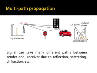
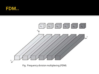
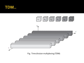


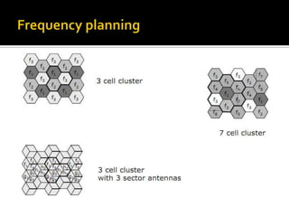

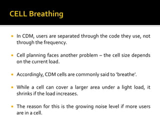


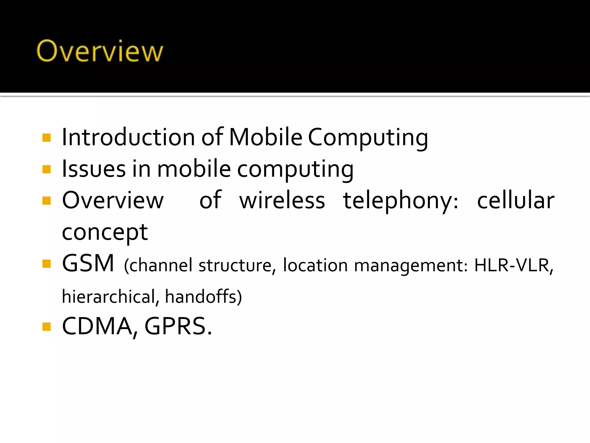


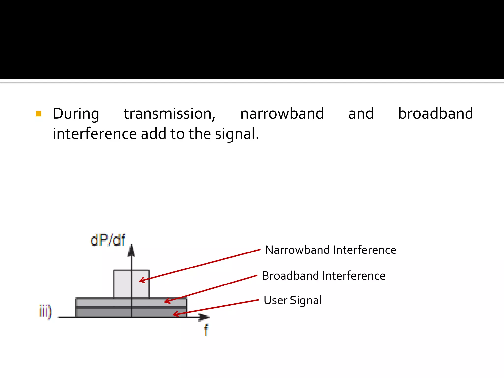
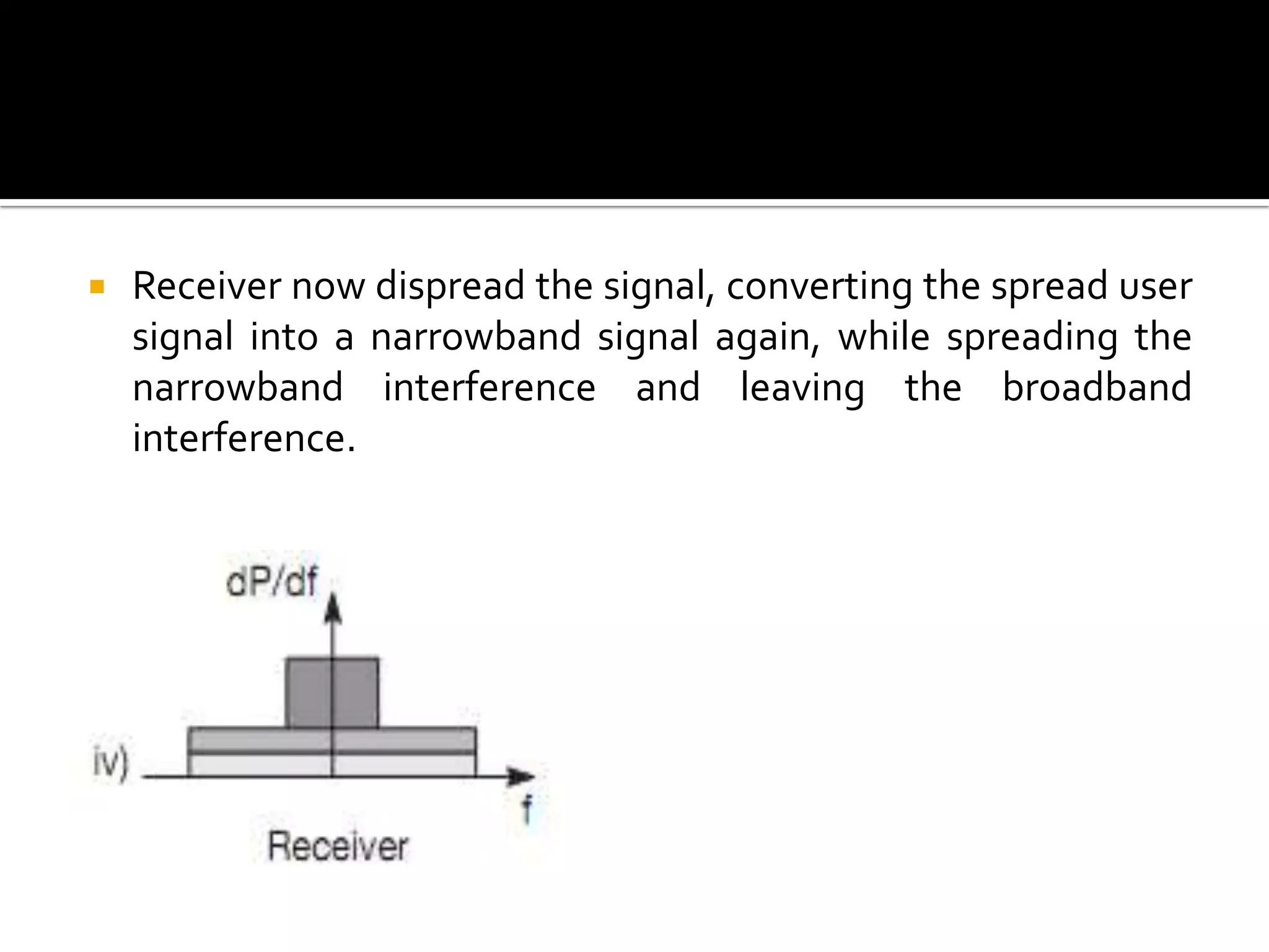
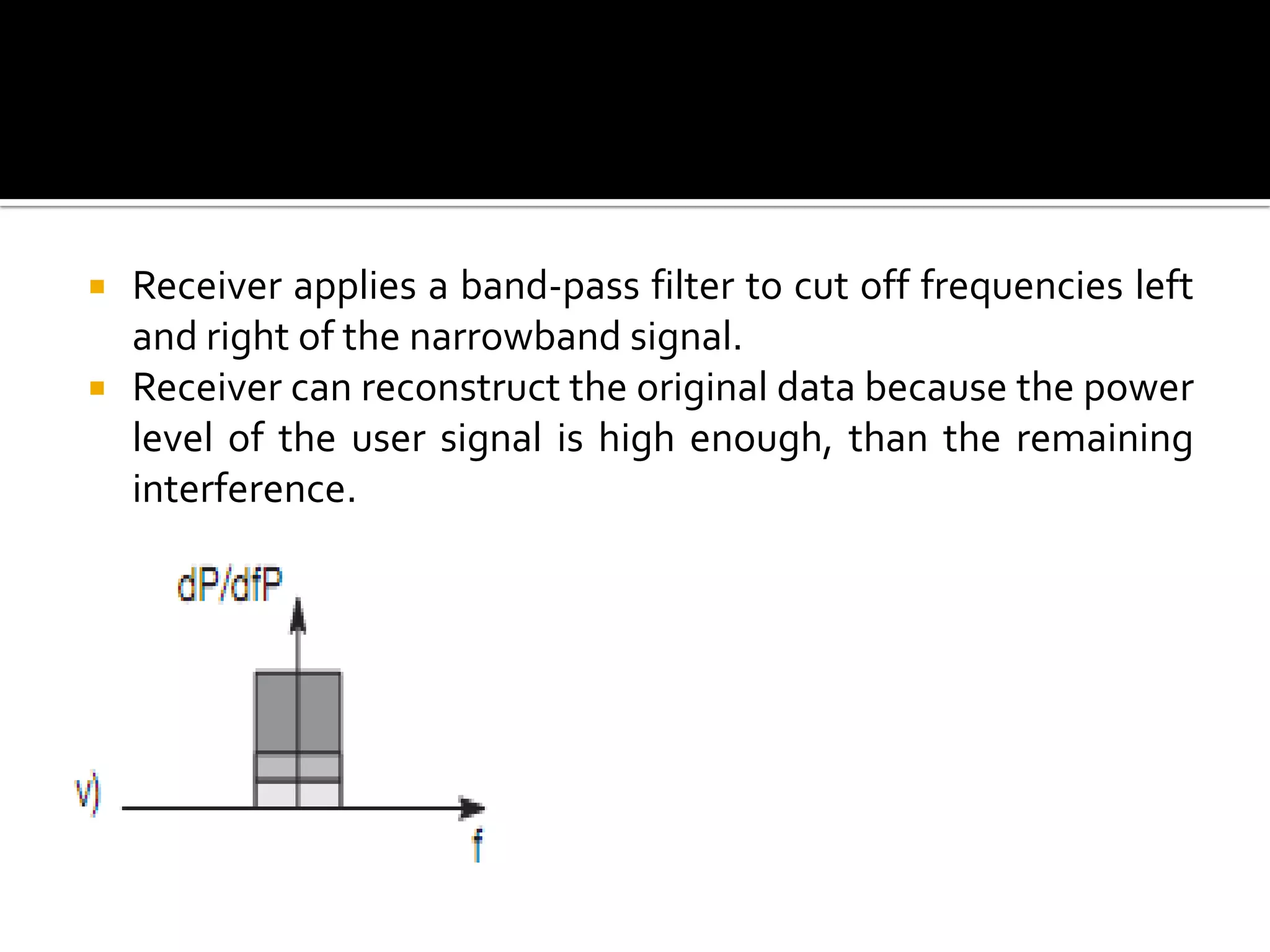


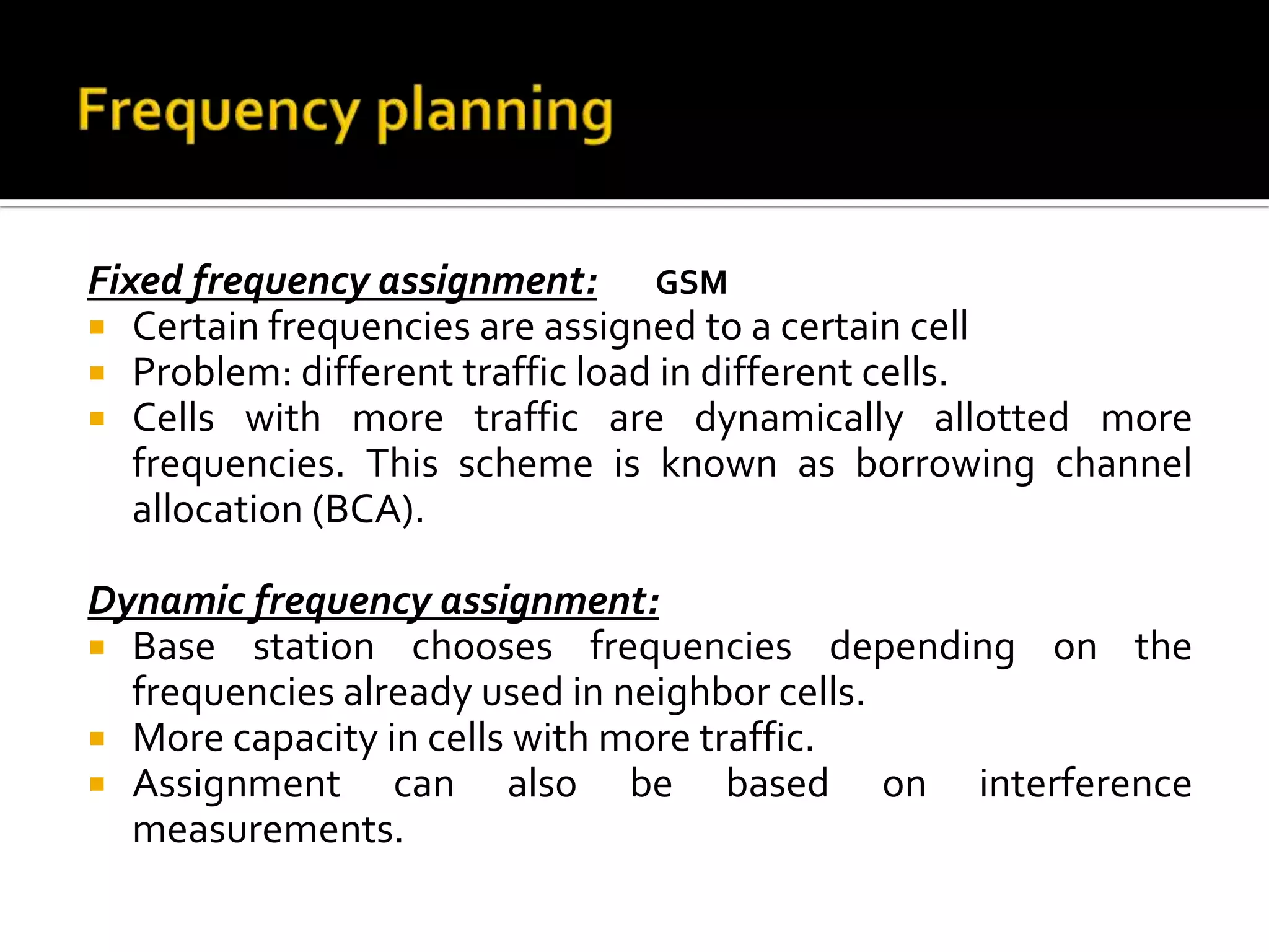
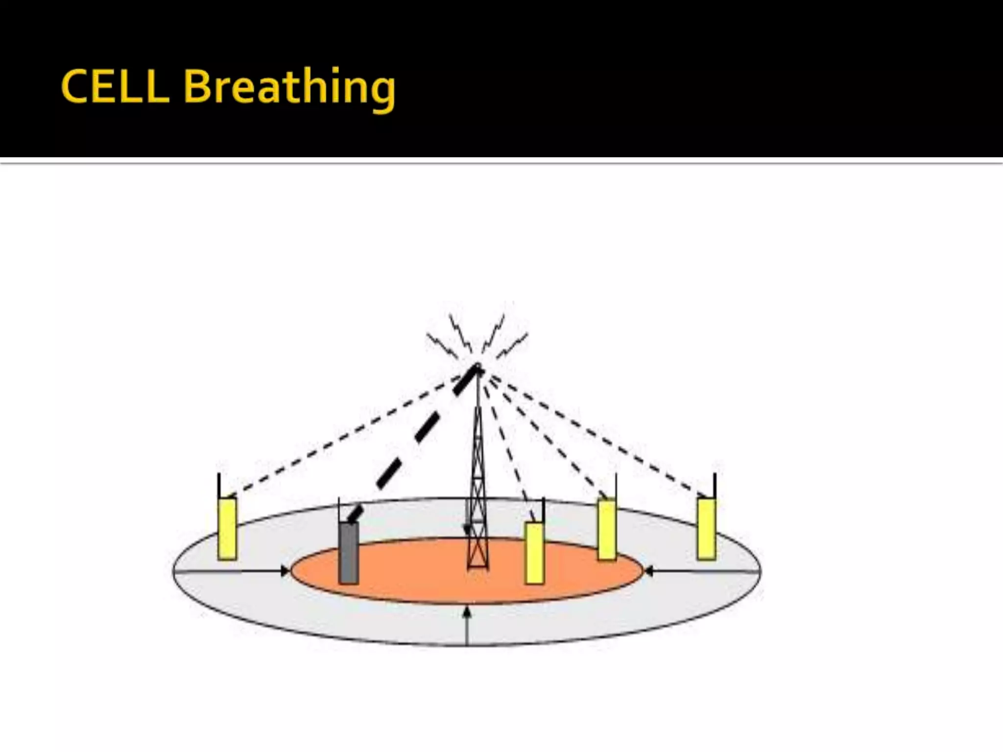


The document provides an overview of key concepts in mobile computing including wireless telephony systems like GSM and CDMA. It discusses issues in mobile computing like interference and time-varying channels. It also covers wireless access technologies, multiple access techniques for sharing wireless spectrum like FDMA, TDMA, CDMA and the cellular concept for enabling frequency reuse in wireless networks.


![UiPath Automation Suite Installation (Hands-On) [2/3]](https://cdn.slidesharecdn.com/ss_thumbnails/automationsuitecommunitysession2-251015095633-a6d862f1-thumbnail.jpg?width=600ounds&width=560&fit=bounds)