This document discusses different techniques for commutating thyristors, which involves turning them off. It describes natural commutation, which occurs in AC circuits as the current passes through zero periodically. Forced commutation is required for DC circuits using external circuits. Class A commutation uses a resonant load to reverse bias the thyristor. Class B uses an LC circuit in parallel. Class D commutation applies a sudden reverse voltage using an auxiliary thyristor to switch a capacitor connected across the main thyristor.
CONTENTS:
Commutation
NaturalCommutation
Forced Commutation
Class A Commutation: Self Commutation by
Resonating Load
Class B Commutation : Self Commutation by
L – C Circuit
Class D Commutation : Impulse
Commutation
3.
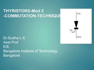
COMMUTATION – TURNINGOFF SCR
The process used for turning off a thyristor is called as commutation.
By the commutation process, the thyristor operating mode is changed
from forward conducting mode to forward blocking mode. ... The
commutation techniques of thyristors are classified into two types:
Natural Commutation. Forced Commutation.
To turn on a thyristor, a low voltage, short duration pulse is applied to the
gate (typically 4V, 100µs).
Once the thyristor is turned-on, the gate loses control and the thyristor
will only turn off when the load current falls virtually to zero, or the
thyristor is reverse biased.
The thyristor will turn off naturally with A.C. supplies as the voltage
reverses This process is called Natural Commutation.
No such reversal occurs with D.C. supplies and it is necessary to force a
voltage reversal if tum-off is to occur. This process is called Forced
Commutation.
4.
COMMUTATION
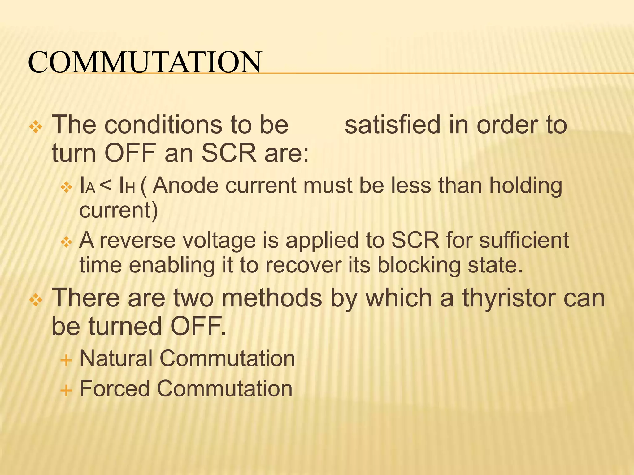
The conditionsto be satisfied in order to
turn OFF an SCR are:
IA < IH ( Anode current must be less than holding
current)
A reverse voltage is applied to SCR for sufficient
time enabling it to recover its blocking state.
There are two methods by which a thyristor can
be turned OFF.
Natural Commutation
Forced Commutation
5.
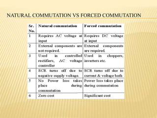
NATURAL COMMUTATION
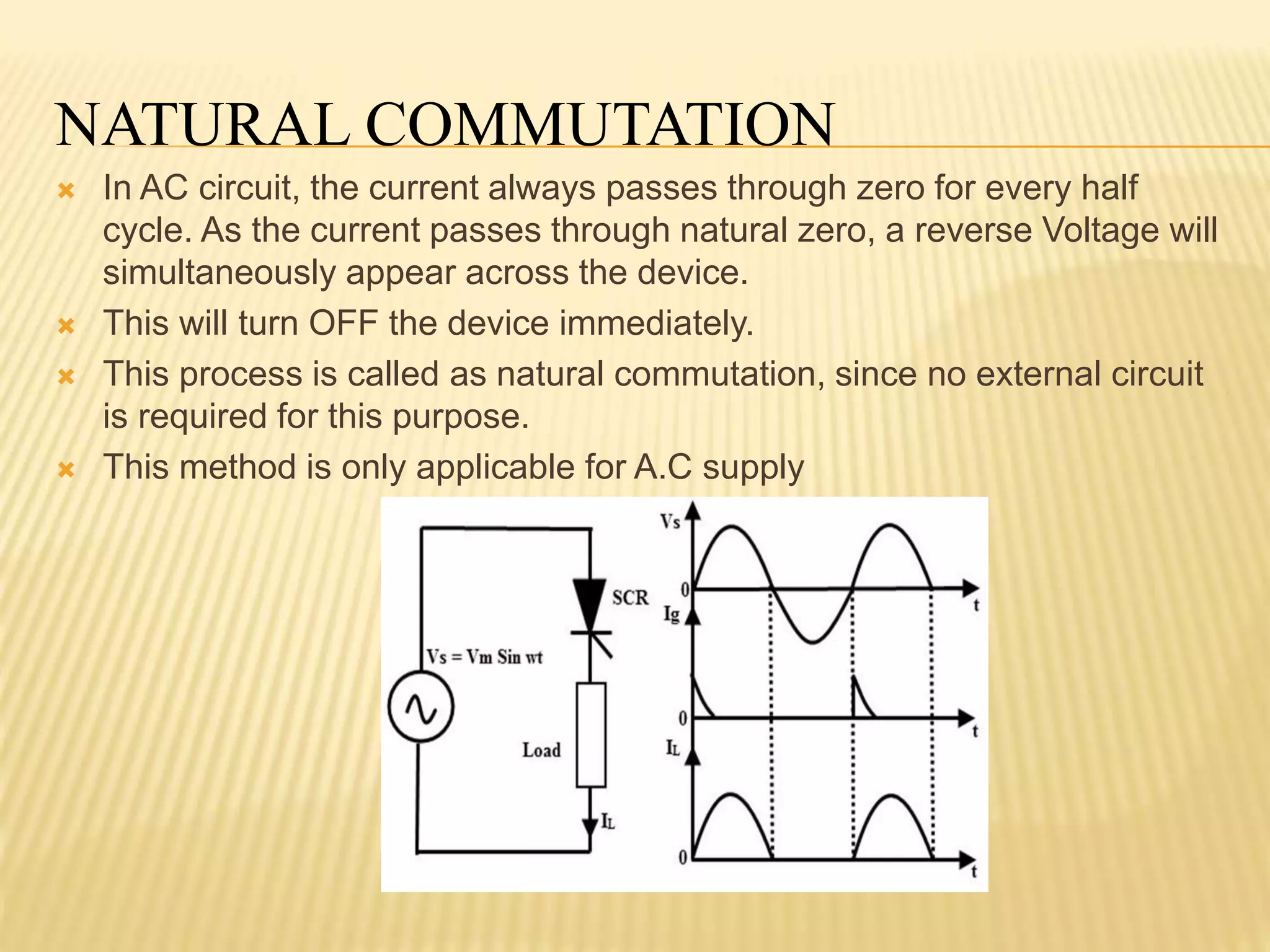
InAC circuit, the current always passes through zero for every half
cycle. As the current passes through natural zero, a reverse Voltage will
simultaneously appear across the device.
This will turn OFF the device immediately.
This process is called as natural commutation, since no external circuit
is required for this purpose.
This method is only applicable for A.C supply
6.
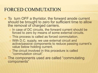
FORCED COMMUTATION
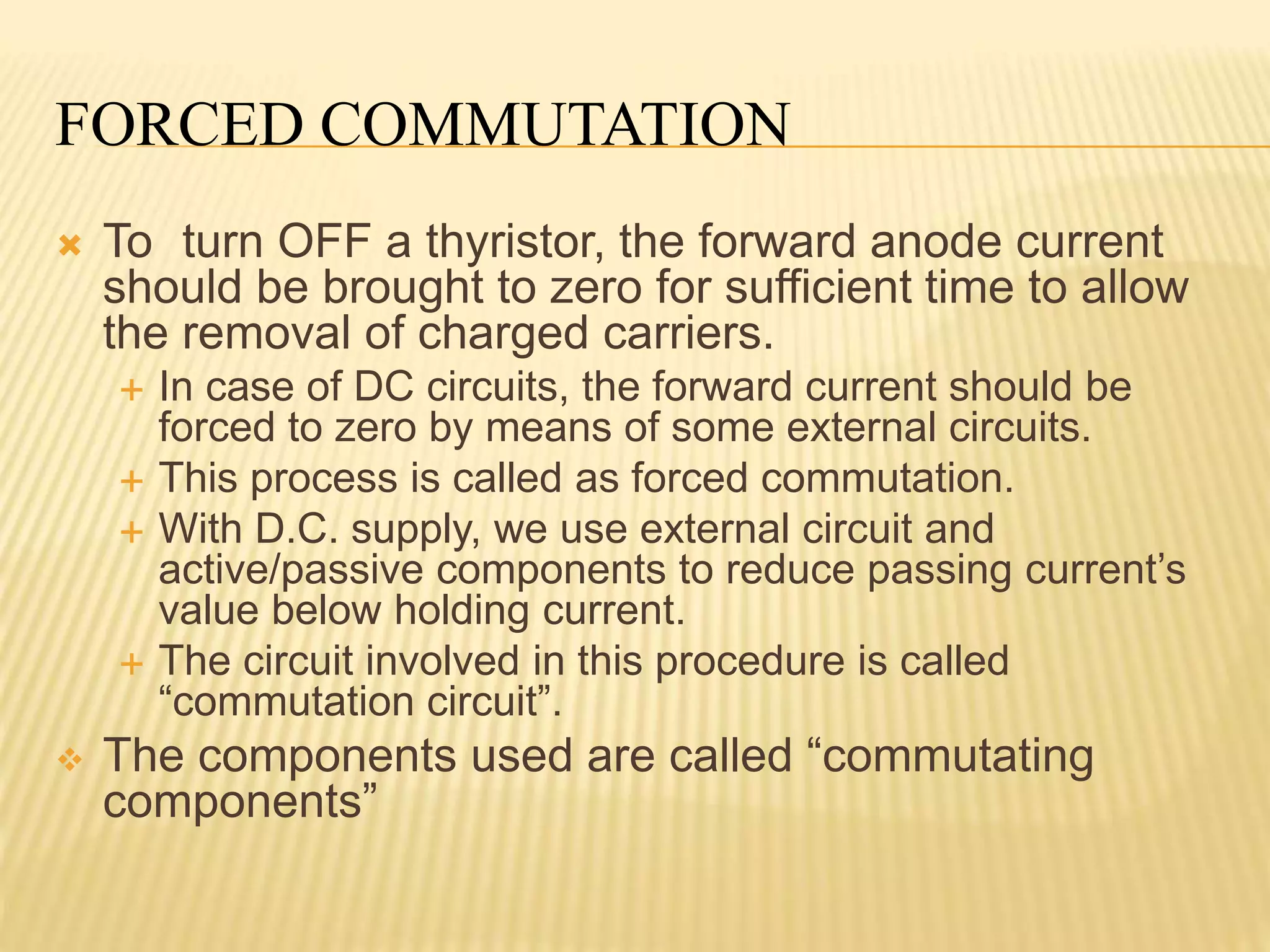
Toturn OFF a thyristor, the forward anode current
should be brought to zero for sufficient time to allow
the removal of charged carriers.
In case of DC circuits, the forward current should be
forced to zero by means of some external circuits.
This process is called as forced commutation.
With D.C. supply, we use external circuit and
active/passive components to reduce passing current’s
value below holding current.
The circuit involved in this procedure is called
“commutation circuit”.
The components used are called “commutating
components”
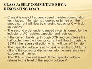
CLASS A: SELFCOMMUTATED BY A
RESONATING LOAD
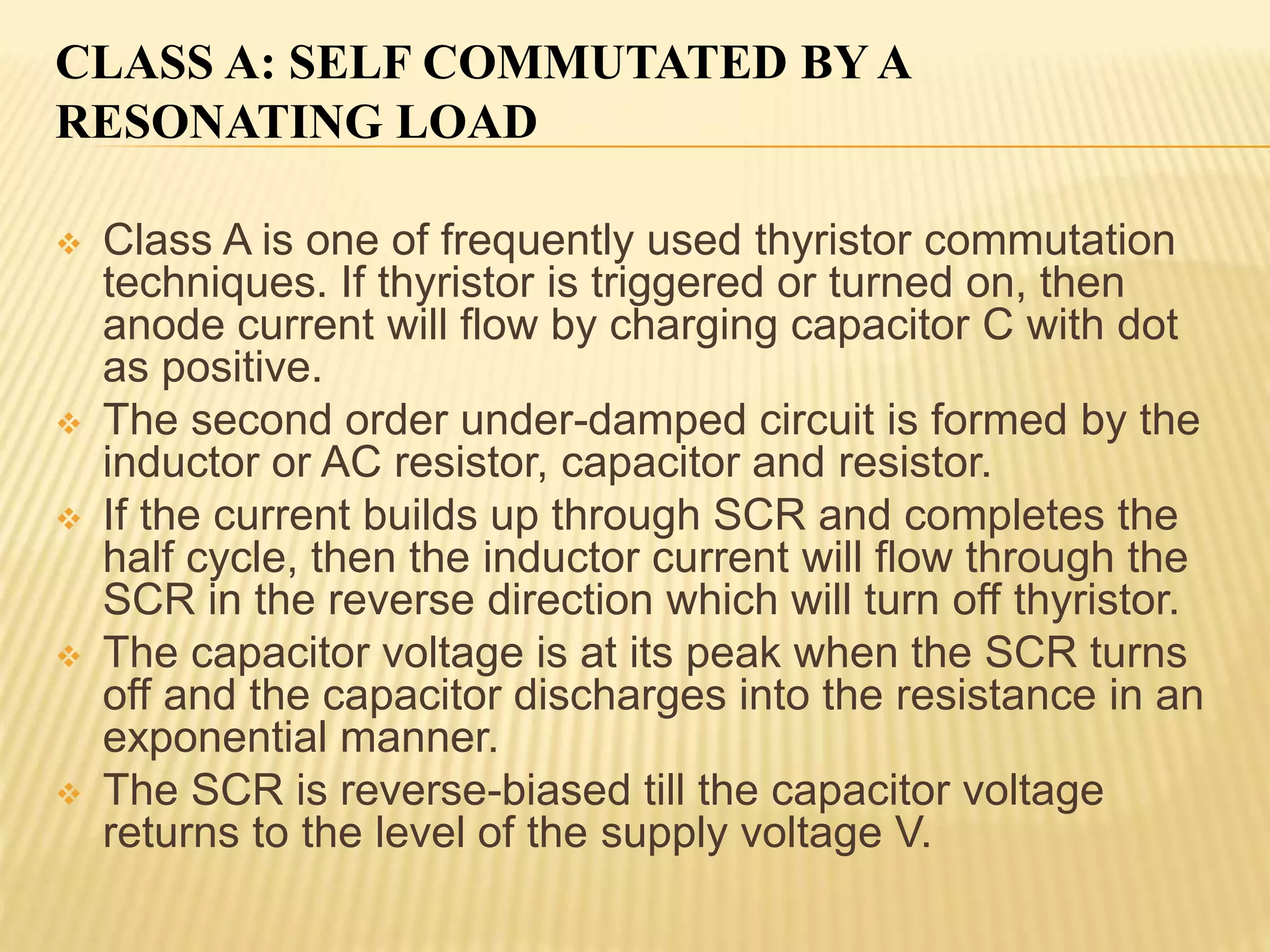
Class A is one of frequently used thyristor commutation
techniques. If thyristor is triggered or turned on, then
anode current will flow by charging capacitor C with dot
as positive.
The second order under-damped circuit is formed by the
inductor or AC resistor, capacitor and resistor.
If the current builds up through SCR and completes the
half cycle, then the inductor current will flow through the
SCR in the reverse direction which will turn off thyristor.
The capacitor voltage is at its peak when the SCR turns
off and the capacitor discharges into the resistance in an
exponential manner.
The SCR is reverse-biased till the capacitor voltage
returns to the level of the supply voltage V.
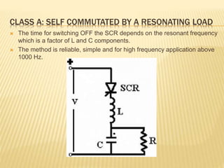
9.
CLASS A: SELFCOMMUTATED BY A RESONATING LOAD
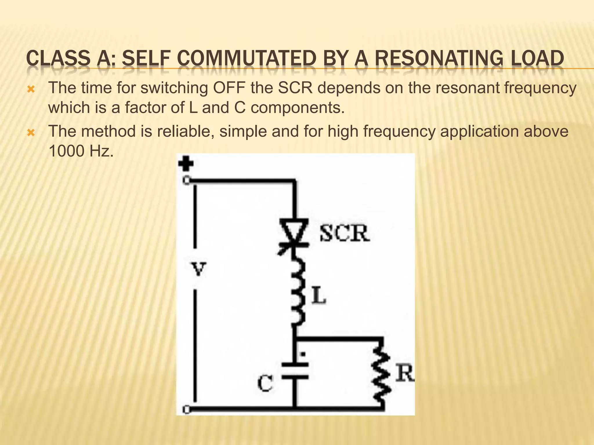
The time for switching OFF the SCR depends on the resonant frequency
which is a factor of L and C components.
The method is reliable, simple and for high frequency application above
1000 Hz.
10.
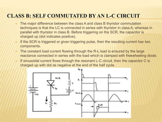
CLASS B: SELFCOMMUTATED BY AN L-C CIRCUIT
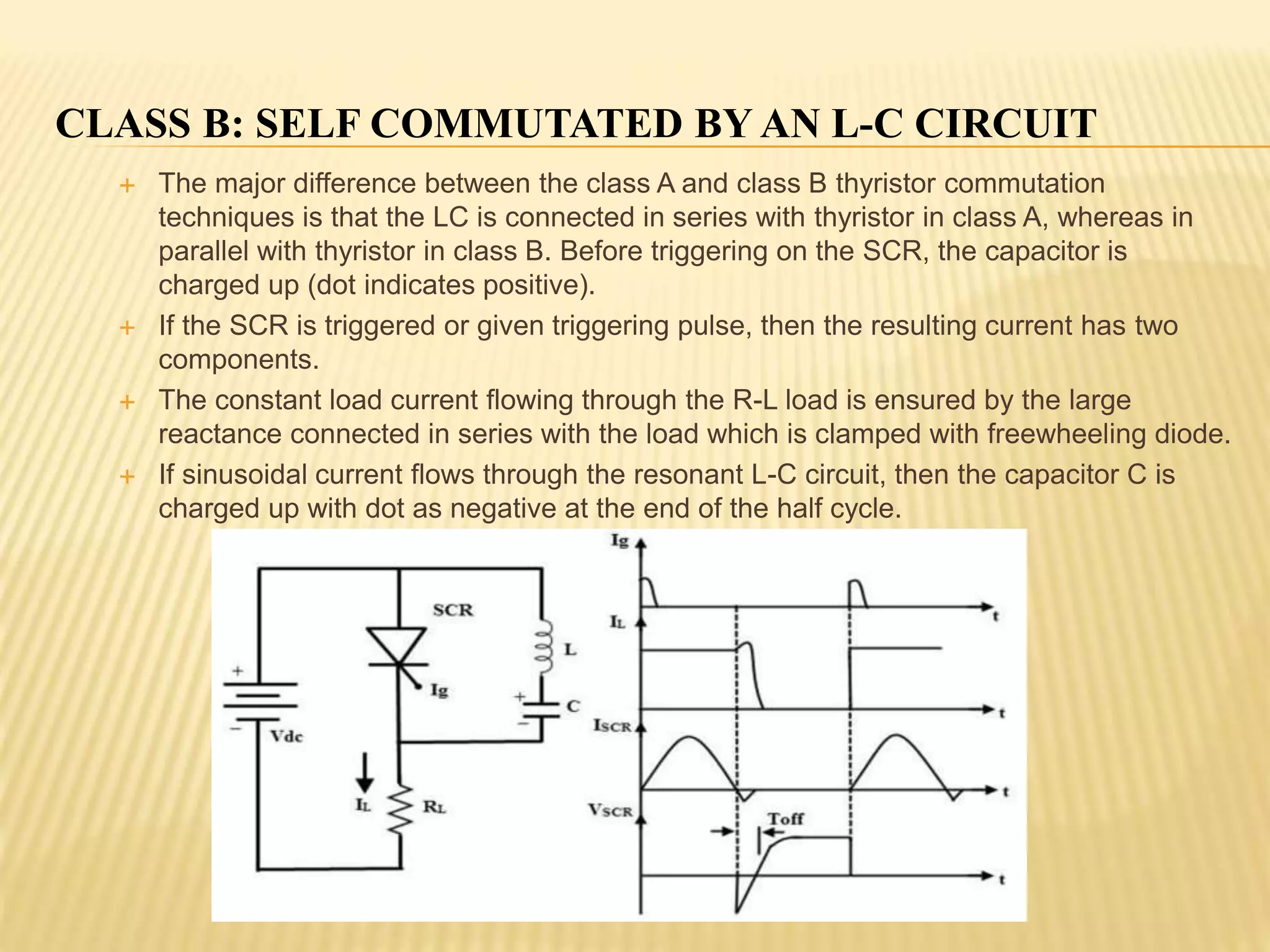
The major difference between the class A and class B thyristor commutation
techniques is that the LC is connected in series with thyristor in class A, whereas in
parallel with thyristor in class B. Before triggering on the SCR, the capacitor is
charged up (dot indicates positive).
If the SCR is triggered or given triggering pulse, then the resulting current has two
components.
The constant load current flowing through the R-L load is ensured by the large
reactance connected in series with the load which is clamped with freewheeling diode.
If sinusoidal current flows through the resonant L-C circuit, then the capacitor C is
charged up with dot as negative at the end of the half cycle.
11.
CLASS D: L-COR C SWITCHED BY ANAUXILIARY SCR
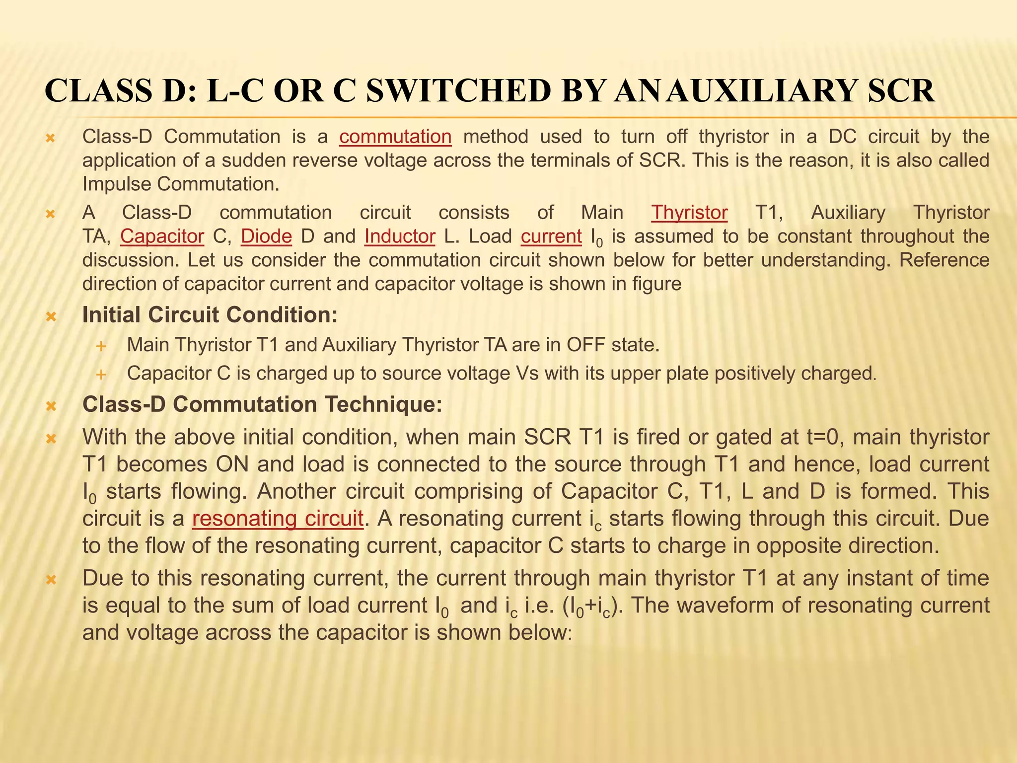
Class-D Commutation is a commutation method used to turn off thyristor in a DC circuit by the
application of a sudden reverse voltage across the terminals of SCR. This is the reason, it is also called
Impulse Commutation.
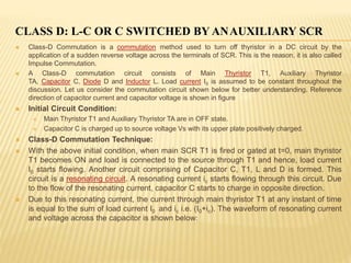
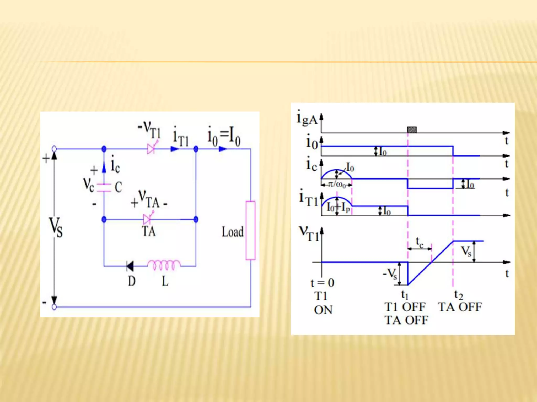
A Class-D commutation circuit consists of Main Thyristor T1, Auxiliary Thyristor
TA, Capacitor C, Diode D and Inductor L. Load current I0 is assumed to be constant throughout the
discussion. Let us consider the commutation circuit shown below for better understanding. Reference
direction of capacitor current and capacitor voltage is shown in figure
Initial Circuit Condition:
Main Thyristor T1 and Auxiliary Thyristor TA are in OFF state.
Capacitor C is charged up to source voltage Vs with its upper plate positively charged.
Class-D Commutation Technique:
With the above initial condition, when main SCR T1 is fired or gated at t=0, main thyristor
T1 becomes ON and load is connected to the source through T1 and hence, load current
I0 starts flowing. Another circuit comprising of Capacitor C, T1, L and D is formed. This
circuit is a resonating circuit. A resonating current ic starts flowing through this circuit. Due
to the flow of the resonating current, capacitor C starts to charge in opposite direction.
Due to this resonating current, the current through main thyristor T1 at any instant of time
is equal to the sum of load current I0 and ic i.e. (I0+ic). The waveform of resonating current
and voltage across the capacitor is shown below:
13.
CLASS D: L-COR C SWITCHED BY ANAUXILIARY SCR
From the above current waveform, it is clear that after t = (π / ω0), the
resonating current becomes zero and Capacitor C gets fully charged up to
source voltage Vs but in opposite direction. This means, after t = (π / ω0),
lower plate of capacitor is positive while the upper plate is negative. It
should also be noted that, after t = (π / ω0), as the diode D gets reversed
biased, no resonating current will flow. This means, the current flowing
through the main thyristor will become I0. This is the reason, ic is shown zero
after t = (π / ω0).
Now, we want to turn off main thyrsistor T1. What will we do? The auxiliary
thyristor TA is fired at t=t1. As soon as auxiliary thyristor TA gets ON, a
sudden reverse voltage equal to the capacitor voltage is impressed across
the main SCR T1. Due to this, the current through main SCR reverses
momentarily to recover the stored charges. Due to this recovery of stored
charges, the current through the main SCR T1 gets quenched and it gets
turned OFF.
Used in inverters and Jones chopper circuit.
https://youtu.be/mYTiCmHWLJI
https://youtu.be/0f5DumypXGg
14.
Let’s seewhat happens after turning OFF of main SCR T1. Once main
thyristor T1 gets OFF, constant load current starts flowing through Capacitor C
and Auxiliary Thyristor TA (as it is still ON). Due to this load current, the
capacitor gets charged from –Vs to +Vs. As the load current is constant, this
charging of capacitor from –Vs to +Vs is linear. When capacitor charges to +Vs,
it will not allow any further flow of load current. Thus current through Auxiliary
Thyristor TA becomes zero and it gets turned OFF. During the time TA is ON
i.e. from t=t1 to t=t2,
Voltage across main thyristor VT1 = Voltage across capacitor = -vc
Load Current I0 = Capacitor Charging Current = -ic
Negative sign is used for voltage and current as it is opposite to the reference
direction shown in circuit diagram. Circuit turn off time is tc.
Class-D commutation is also known as Auxiliary Commutation due to the fact
that Auxiliary Thyristor is used for the commutation of main thyristor. When
auxiliary thyristor is ON, capacitor gets connected across the terminals of main
thyristor, therefore this method of commutation is also called Parallel Capacitor
Commutation.


![Commutation Circuits[Autosaved].ppt](https://cdn.slidesharecdn.com/ss_thumbnails/commutationcircuitsautosaved-221126072740-13260497-thumbnail.jpg?width=600ounds&width=560&fit=bounds)


