Introduction
One ofthe basic features of a computer is its ability to exchange
data with other devices.
Enables a human operator to use a keyboard and a display
screen to process text and graphics.
Computers are an integral part of home appliances,
manufacturing equipment, transportation systems, banking
and point-of-sale terminals.
Input to a computer may come from a sensor switch, a digital
camera, a
microphone, or a fire alarm.
Output may be a sound signal to be sent to a speaker or a digitally
coded command to change the speed of a motor, open a valve, or
cause a robot to move in a specified manner.
In short, a general-purpose computer should have the
ability to exchange information with a wide range of
devices in varying environments.
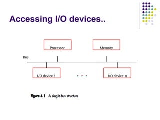
Accessing I/O devices
A simple arrangement to connect I/O
devices to a computer is to use a single
bus arrangement.
The bus enables all the devices connected
to it to exchange information.
It consists of three sets of lines used to
carry address, data, and control signals.
Each I/O device is assigned a unique set
of addresses.
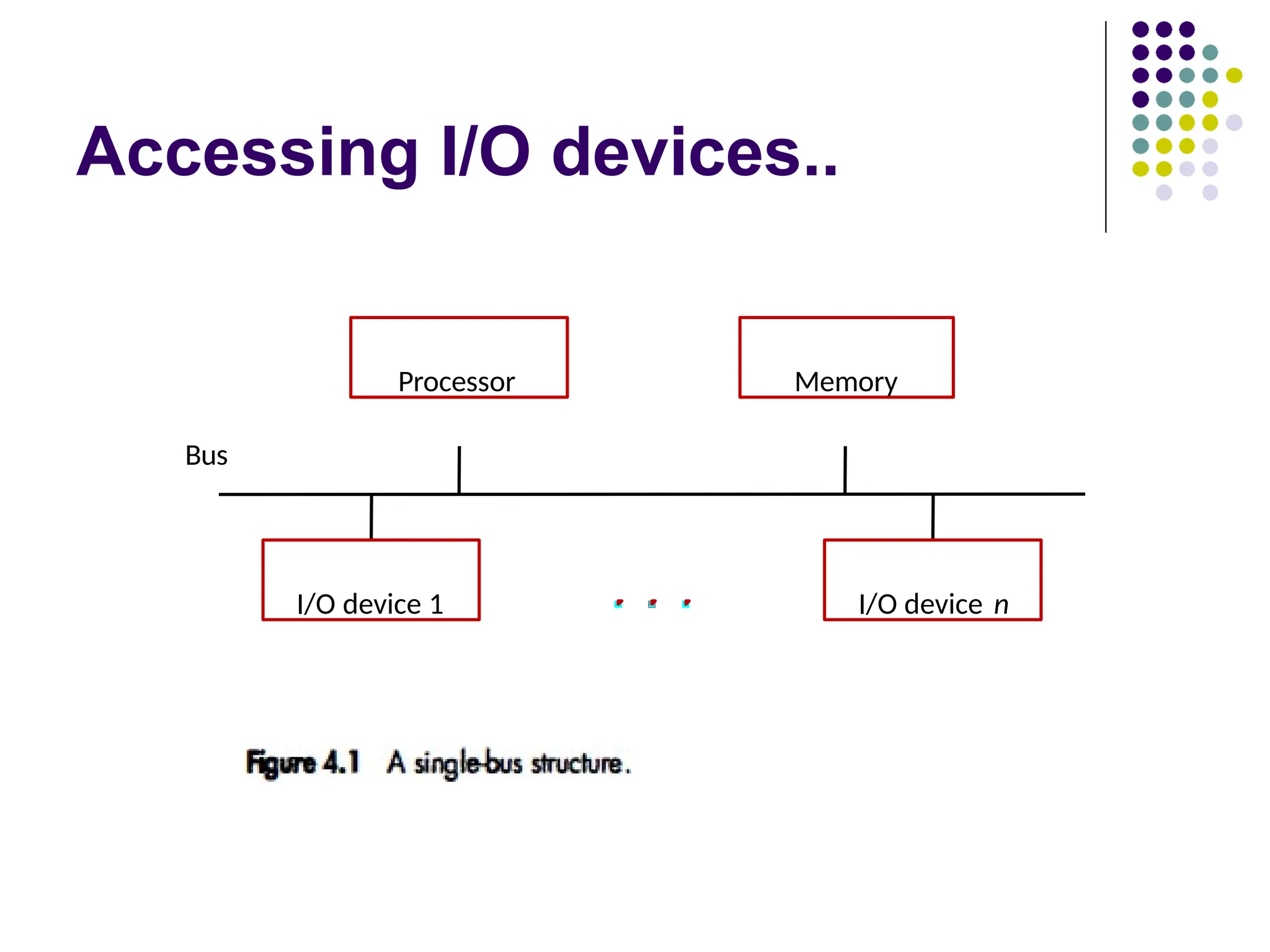
Accessing I/O devices..
To access an I/O device, the processor
places the address on the address
lines.
The device recognizes the address,
and responds to the control signals.
The processor requests either a read or
a write operation, and the requested
data are transferred over the data lines.
8.
Accessing I/O devices..
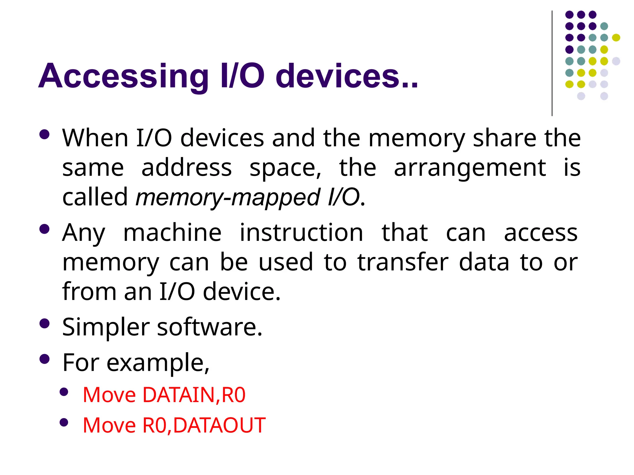
When I/O devices and the memory share the
same address space, the arrangement is
called memory-mapped I/O.
Any machine instruction that can access
memory can be used to transfer data to or
from an I/O device.
Simpler software.
For example,
Move DATAIN,R0
Move R0,DATAOUT
9.
Accessing I/O devices..
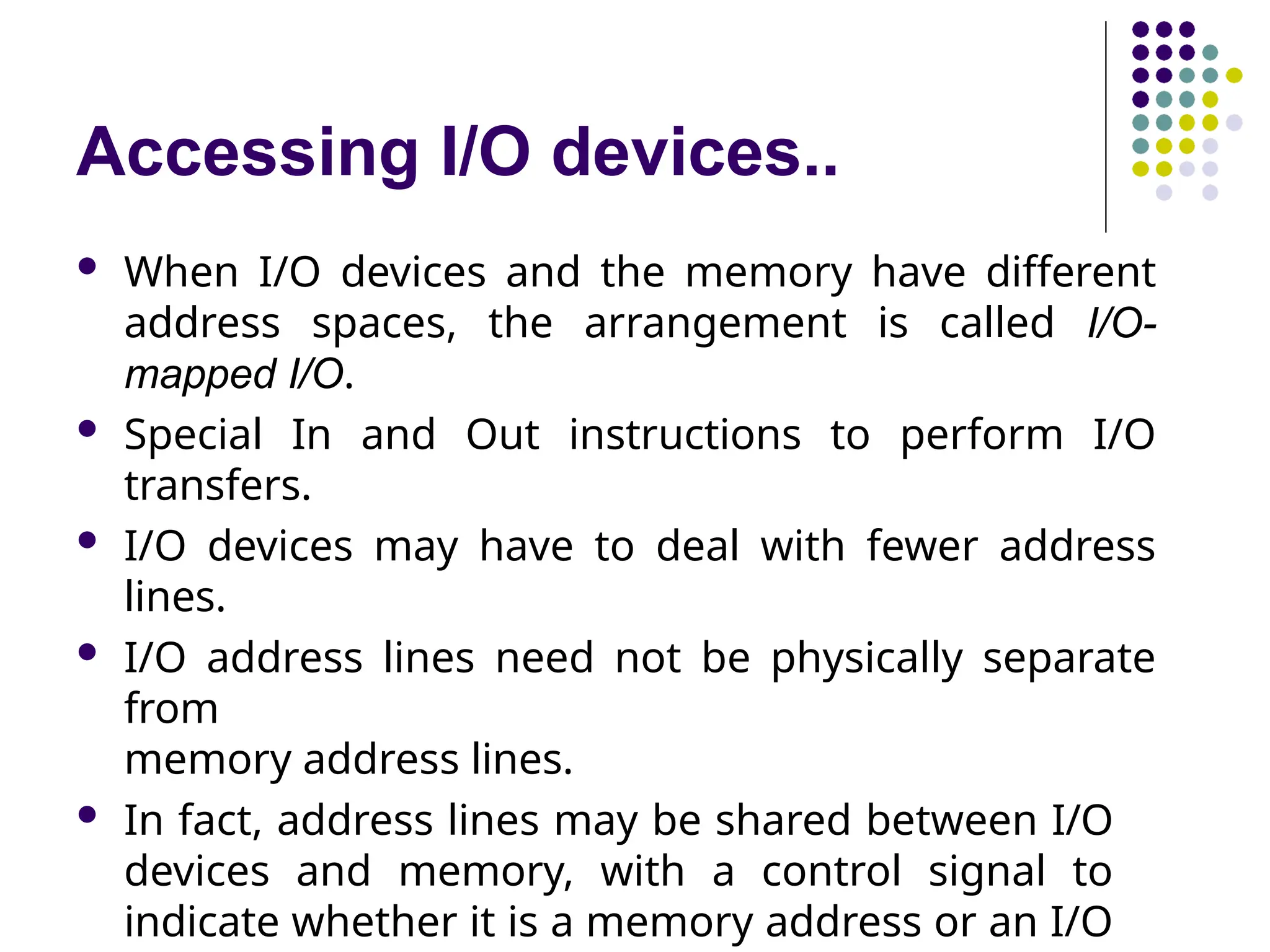
When I/O devices and the memory have different
address spaces, the arrangement is called I/O-
mapped I/O.
Special In and Out instructions to perform I/O
transfers.
I/O devices may have to deal with fewer address
lines.
I/O address lines need not be physically separate
from
memory address lines.
In fact, address lines may be shared between I/O
devices and memory, with a control signal to
indicate whether it is a memory address or an I/O
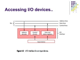
Accessing I/O devices..
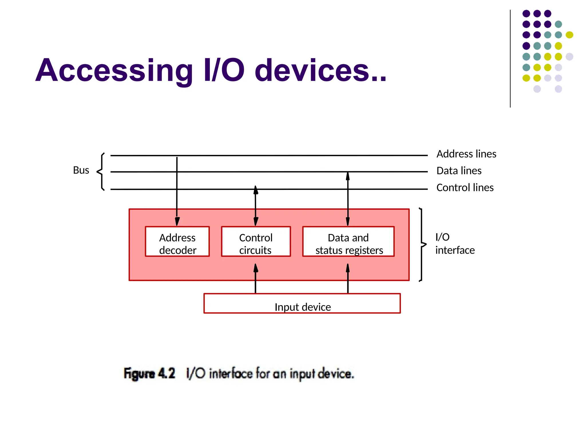
Figure 4.2 illustrates the hardware
required to connect an I/O device to
the bus.
I/O device is connected to the bus
using an I/O interface circuit which
has:
Address decoder
Control circuit
Data and status registers.
12.
Accessing I/O devices..
Address decoder enables the device to recognize
its address when this address appears on the
address lines.
Data register holds the data being transferred to
or from
the processor.
The status register contains information relevant
to the
operation of the I/O device.
Data and status registers are connected to the
data bus,
and have unique addresses.
I/O interface circuit coordinates I/O transfers.
13.
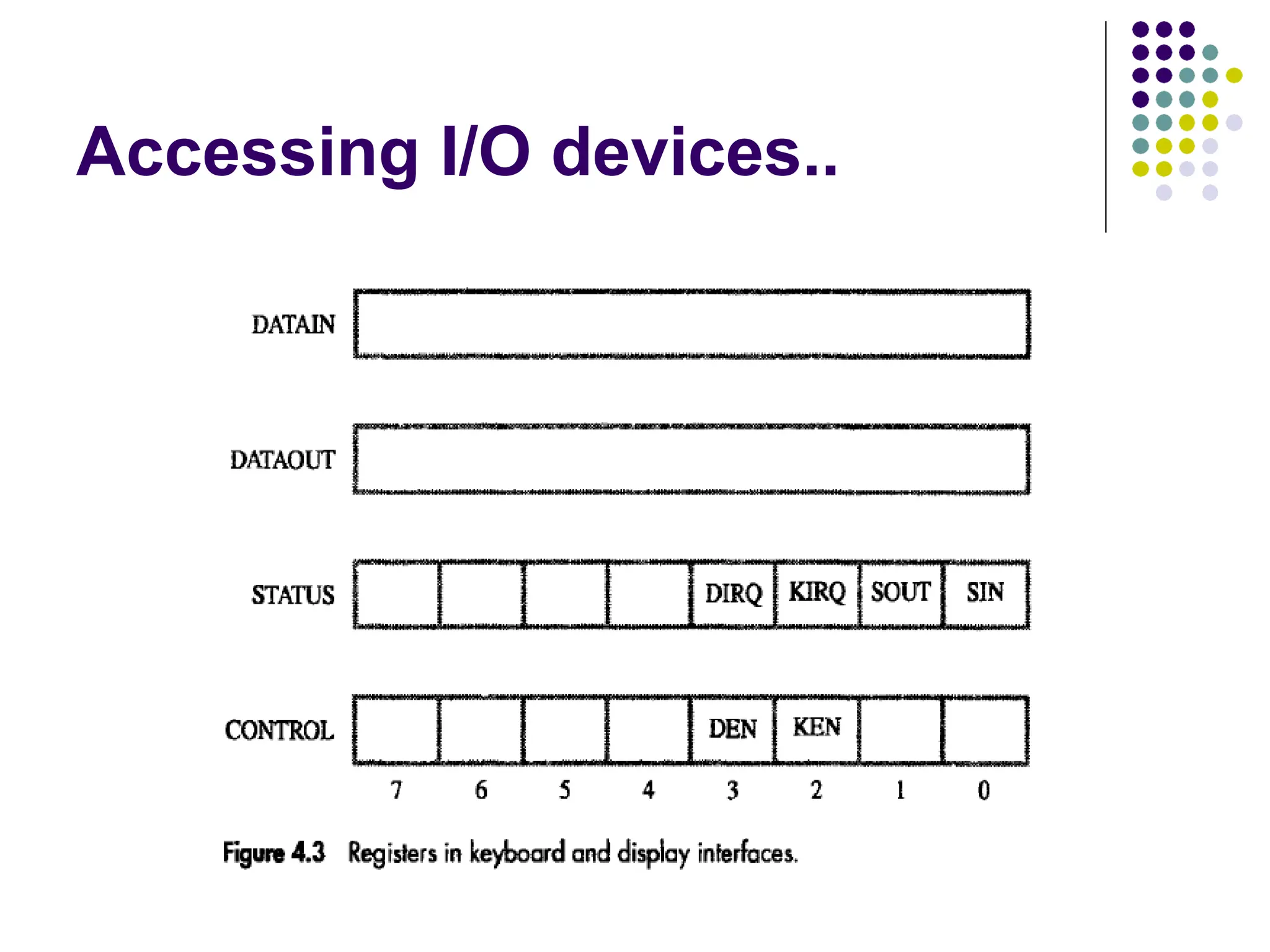
Accessing I/O devices..
Recall that the rate of transfer to and from I/O
devices is slower than the speed of the processor.
This creates the need for mechanisms to synchronize data
transfers between them.
To review the basic concepts, let us consider a
simple example of I/O operations involving a
keyboard and a display device in a computer
system.
The four registers shown in Figure 4.3 are used in
the
data transfer operations.
14.
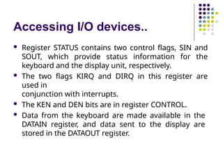
Accessing I/O devices..
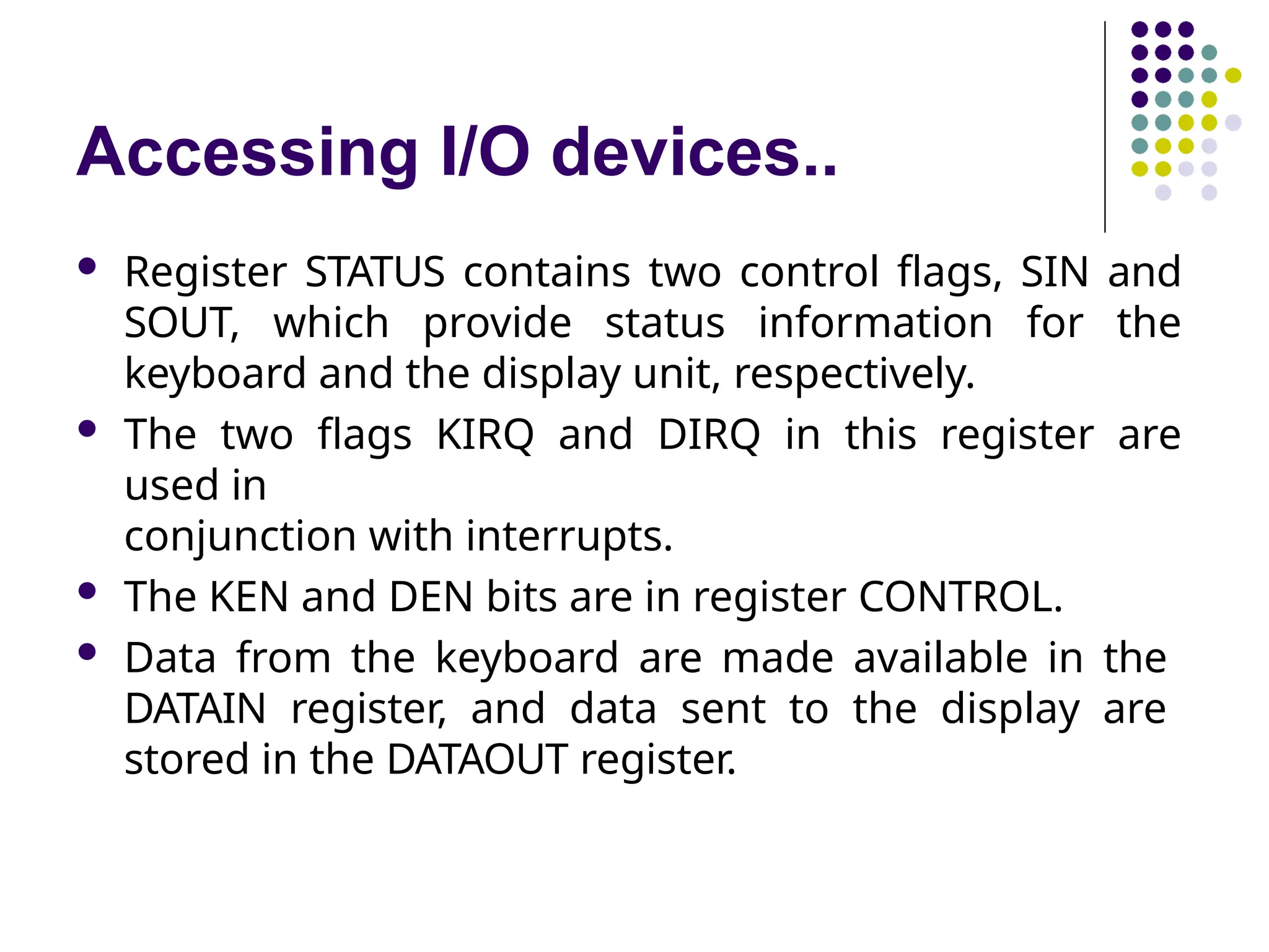
Register STATUS contains two control flags, SIN and
SOUT, which provide status information for the
keyboard and the display unit, respectively.
The two flags KIRQ and DIRQ in this register are
used in
conjunction with interrupts.
The KEN and DEN bits are in register CONTROL.
Data from the keyboard are made available in the
DATAIN register, and data sent to the display are
stored in the DATAOUT register.
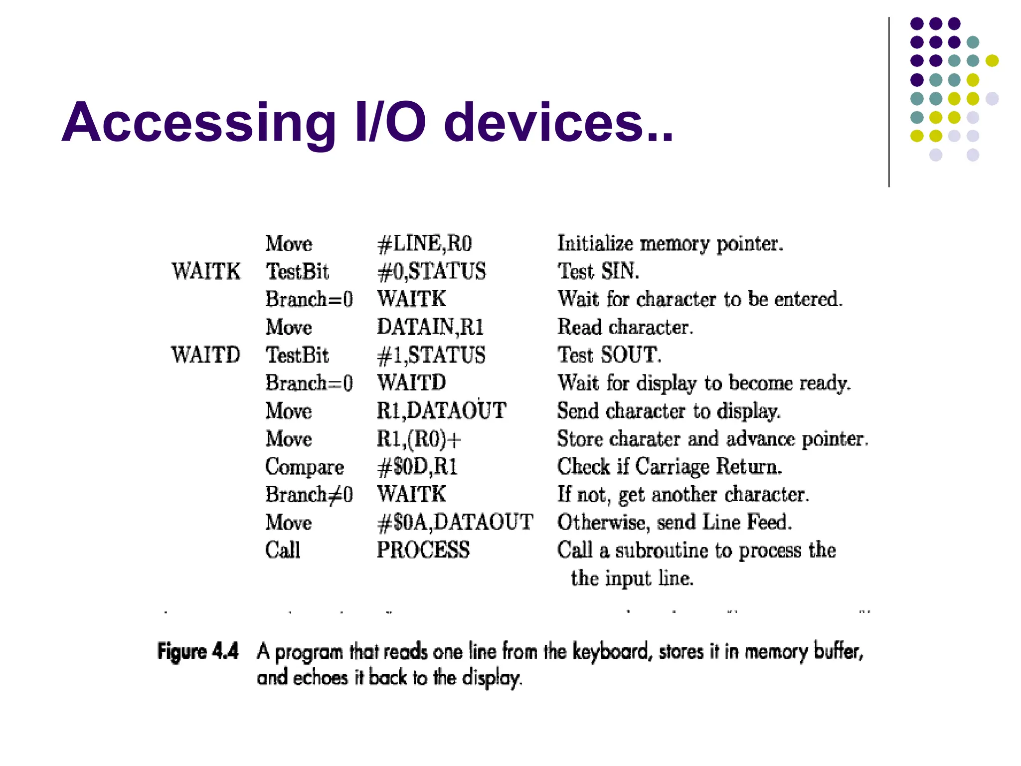
Accessing I/O devices..
This program reads a line of characters from
the keyboard and stores it in a memory
buffer starting at location LINE.
Then, it calls a subroutine PROCESS to
process the input line.
As each character is read, it is echoed back
to the display.
Register R0 is used as a pointer to the
memory buffer area.
18.
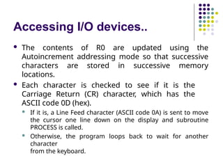
Accessing I/O devices..
The contents of R0 are updated using the
Autoincrement addressing mode so that successive
characters are stored in successive memory
locations.
Each character is checked to see if it is the
Carriage Return (CR) character, which has the
ASCII code 0D (hex).
If it is, a Line Feed character (ASCII code 0A) is sent to move
the cursor one line down on the display and subroutine
PROCESS is called.
Otherwise, the program loops back to wait for another
character
from the keyboard.
19.
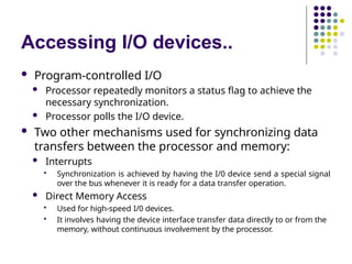
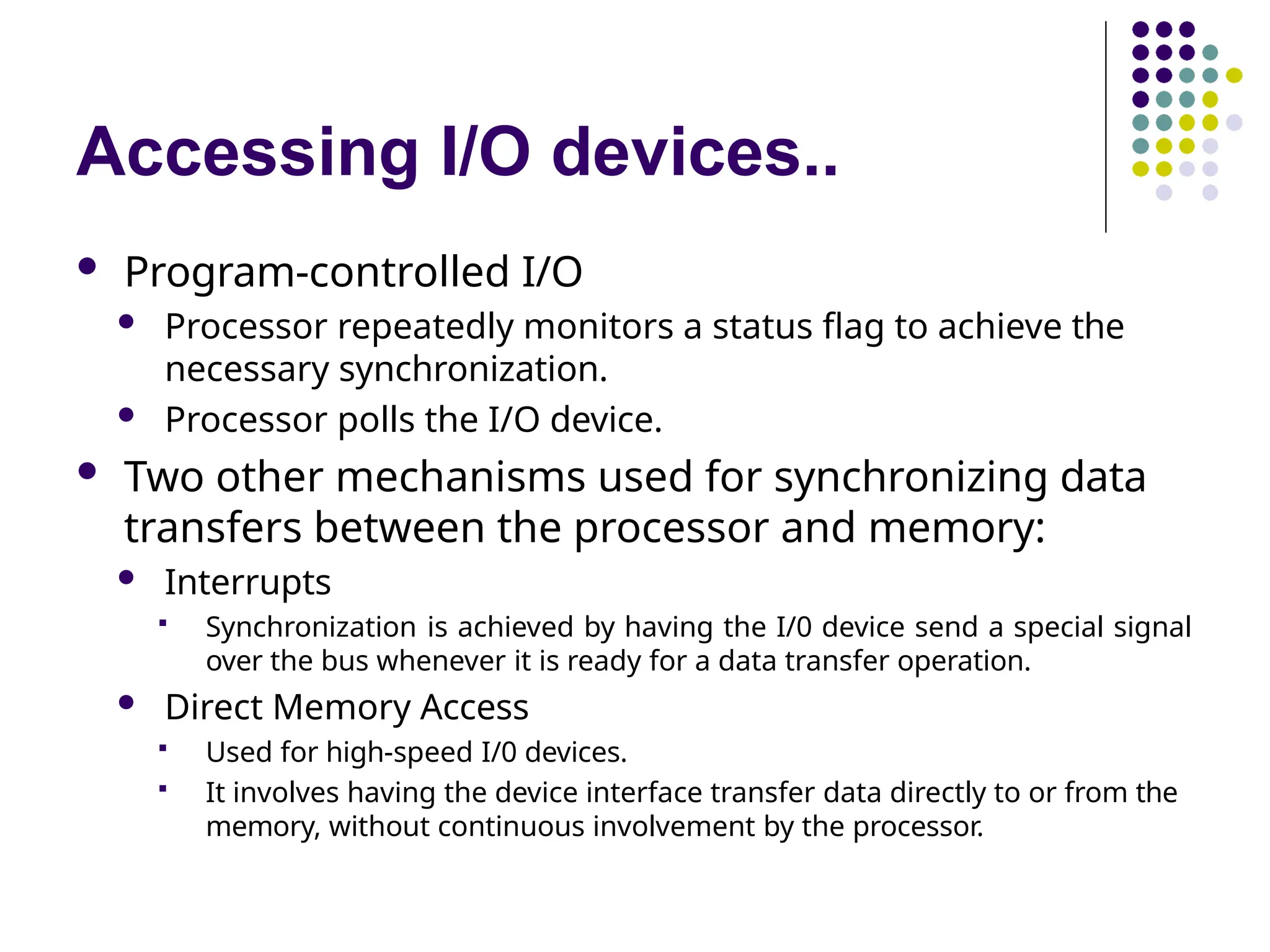
Accessing I/O devices..
Program-controlled I/O
Processor repeatedly monitors a status flag to achieve the
necessary synchronization.
Processor polls the I/O device.
Two other mechanisms used for synchronizing data
transfers between the processor and memory:
Interrupts
Synchronization is achieved by having the I/0 device send a special signal
over the bus whenever it is ready for a data transfer operation.
Direct Memory Access
Used for high-speed I/0 devices.
It involves having the device interface transfer data directly to or from the
memory, without continuous involvement by the processor.
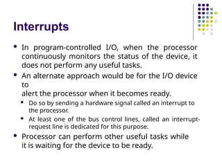
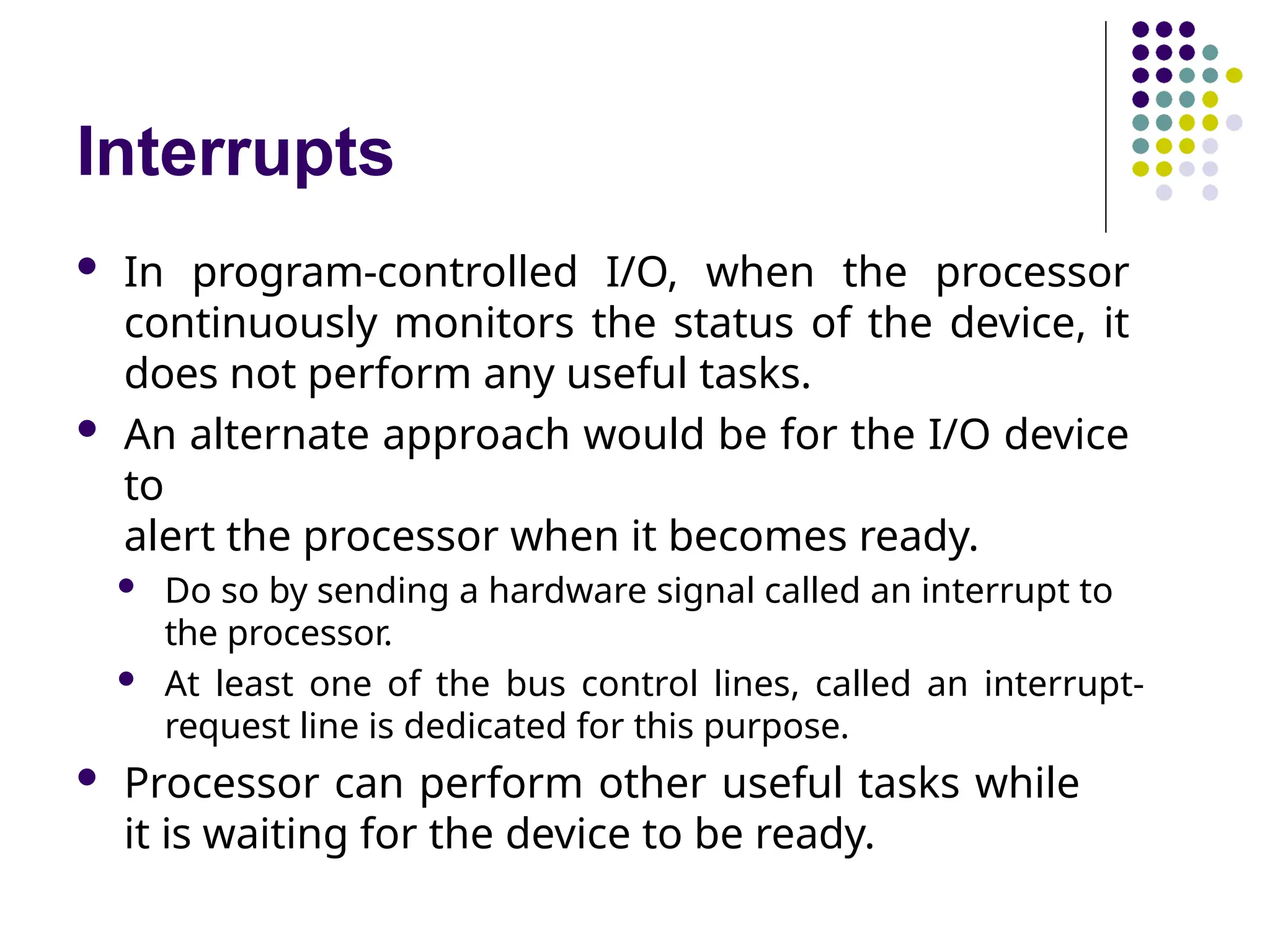
Interrupts
In program-controlledI/O, when the processor
continuously monitors the status of the device, it
does not perform any useful tasks.
An alternate approach would be for the I/O device
to
alert the processor when it becomes ready.
Do so by sending a hardware signal called an interrupt to
the processor.
At least one of the bus control lines, called an interrupt-
request line is dedicated for this purpose.
Processor can perform other useful tasks while
it is waiting for the device to be ready.
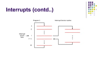
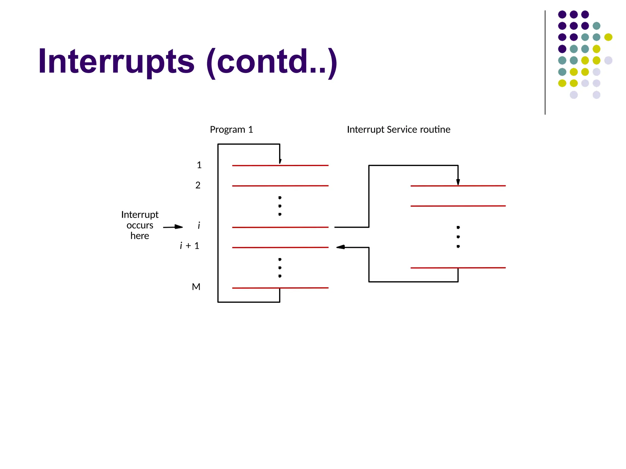
Interrupts..
Processor isexecuting the instruction located at
address i when an interrupt occurs.
Routine executed in response to an interrupt request
is
called the interrupt-service routine.
When an interrupt occurs, control must be
transferred to
the interrupt service routine.
But before transferring control, the current contents
of
the PC (i+1), must be saved in a known location.
This will enable the return-from-interrupt instruction
to
24.
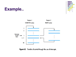
Example..
Consider atask that requires some computations to
be performed and the results to be printed on a line
printer.
Let the program consist of two routines, COMPUTE
and
PRINT.
Assume that COMPUTE produces a set of n lines of
output, to be printed by the PRINT routine.
First, the COMPUTE routine is executed to produce
the
first n lines of output.
Then, the PRINT routine is executed to send the first
line
25.
Example..
At thispoint, instead of waiting for the line to be
printed; the PRINT routine may be temporarily
suspended and execution of the COMPUTE routine
continued.
Whenever the printer becomes ready, it alerts the
processor by sending an interrupt-request signal.
In response, the processor interrupts execution of
the COMPUTE routine and transfers control to the
PRINT routine.
The PRINT routine sends the second line to the
printer
and is again suspended.
Then the interrupted COMPUTE routine resumes
26.
Example..
This processcontinues until all n lines have been
printed and the PRINT routine ends.
The PRINT routine will be restarted whenever the
next
set of n lines is available for printing.
If COMPUTE takes longer to generate n lines than
the time required to print them, the processor will
be performing useful computations all the time.
Interrupts..
When aprocessor receives an interrupt-
request, it must branch to the interrupt
service routine.
It must also inform the device that it
has recognized the interrupt request.
This can be accomplished in two
ways:
Some processors have an explicit
interrupt-
acknowledge signal for this purpose.
In other cases, the data transfer that takes place
between the device and the processor can be
used to inform the device.
29.
Interrupts..
Treatment ofan interrupt-service routine is very
similar to that of a subroutine.
However there are significant differences:
A subroutine performs a task that is required by the calling program.
Interrupt-service routine may not have anything in common with the
program it interrupts.
Interrupt-service routine and the program that it interrupts may
belong to
different users.
As a result, before branching to the interrupt-service routine, not
only the PC, but other information such as condition code flags, and
processor registers used by both the interrupted program and the
interrupt service routine must be stored.
This will enable the interrupted program to resume execution upon
return from
interrupt service routine.
30.
Interrupts..
Saving andrestoring information can be done
automatically
by the processor or explicitly by program instructions.
Saving and restoring registers involves memory transfers:
Increases the total execution time.
Increases the delay between the time an interrupt request is
received, and the start of execution of the interrupt-service
routine. This delay is called interrupt latency.
In order to reduce the interrupt latency, most
processors save
only the minimal amount of information:
This minimal amount of information includes Program
Counter and processor status registers.
Any additional information that must be saved, must be saved
explicitly by the program instructions at the beginning of the
interrupt service routine.
31.
Interrupts..
An interruptis more than a simple
mechanism for coordinating I/O transfers.
The concept of interrupts is used in operating
systems and in many control applications where
processing of certain routines must be accurately
timed relative to external events.
Real-time processing.
32.
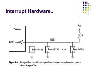
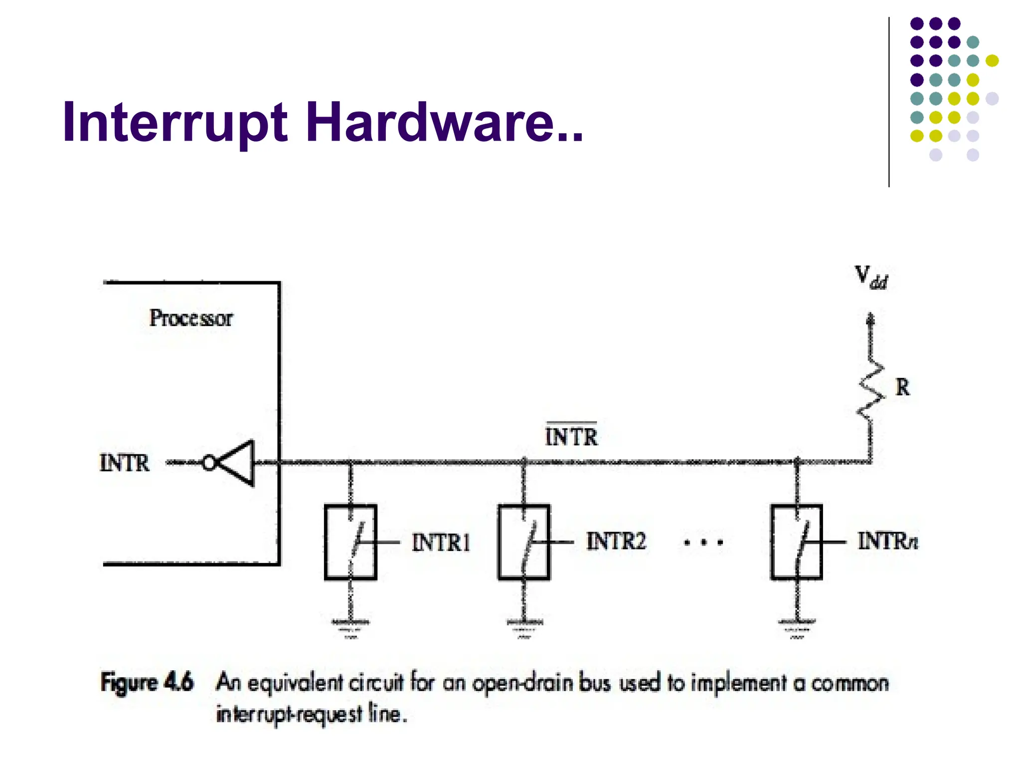
Interrupt Hardware
AnI/O device requests an interrupt by
activating a bus line called interrupt-request.
Most computers are likely to have several
I/O devices that can request an interrupt.
A single interrupt-request line may be
used to serve n devices as depicted in
Figure 4.6.
All devices are connected to the line
via switches to ground.
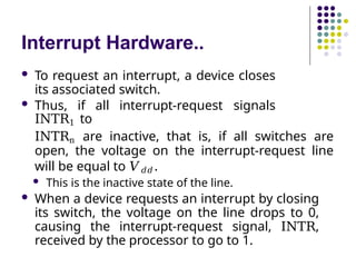
Interrupt Hardware..
Torequest an interrupt, a device closes
its associated switch.
Thus, if all interrupt-request signals
INTR1 to
INTRn are inactive, that is, if all switches are
open, the voltage on the interrupt-request line
will be equal to 𝑉𝑑𝑑 .
This is the inactive state of the line.
When a device requests an interrupt by closing
its switch, the voltage on the line drops to 0,
causing the interrupt-request signal, INTR,
received by the processor to go to 1.
35.
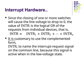
Interrupt Hardware..
Sincethe closing of one or more switches
will cause the line voltage to drop to 0, the
value of INTR is the logical OR of the
requests from individual devices, that is,
INTR = INTR1 + INTR2 + ⋯ + INTRn
It is customary to use the complemented
form,
INTR, to name the interrupt-request signal
on the common line, because this signal is
active when in the low-voltage state.
36.
Interrupt Hardware..
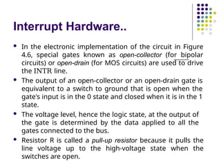
Inthe electronic implementation of the circuit in Figure
4.6, special gates known as open-collector (for bipolar
circuits) or open-drain (for MOS circuits) are used to drive
the INTR line.
The output of an open-collector or an open-drain gate is
equivalent to a switch to ground that is open when the
gate's input is in the 0 state and closed when it is in the 1
state.
The voltage level, hence the logic state, at the output of
the gate is determined by the data applied to all the
gates connected to the bus.
Resistor R is called a pull-up resistor because it pulls the
line voltage up to the high-voltage state when the
switches are open.
37.
Enabling and Disabling
Interrupts
The arrival of an interrupt request from an external
device causes the processor to suspend the
execution of one program and start the execution of
another.
Because interrupts can arrive at any time, they may
alter the intended sequence of events
Sometimes such alterations may be undesirable, and must
not be
allowed.
For example, the processor may not want to be interrupted
by the
same device while executing its interrupt-service routine.
38.
Enabling and Disabling
Interrupts..
There are many situations in which the
processor should ignore interrupt
requests.
For example, in the case of the Compute-
Print program of Figure 4.5, an interrupt
request from the printer should be accepted
only if there are output lines to be printed.
After printing the last line of a set of n
lines, interrupts should be disabled until
another set becomes available for printing.
39.
Enabling and Disabling
Interrupts..
In another case, it may be necessary to guarantee
that a particular sequence of instructions is executed
to the end without interruption.
The interrupt-service routine may change some of
the data used by the instructions in question.
Processors generally provide the ability to enable
and disable such interruptions as desired.
One simple way is to provide machine instructions
such as Interrupt-enable and Interrupt-disable for this
purpose.
40.
Enabling and Disabling
Interrupts..
Consider the specific case of a single interrupt
request from one device.
When a device activates the interrupt-request
signal, it keeps this signal activated until
acknowledgement.
This means that the interrupt-request signal will be
active during execution of the interrupt-service
routine.
It is essential to ensure that this active request
signal does not lead to successive interruptions,
causing the system to enter an infinite loop from
which it cannot recover.
41.
Enabling and Disabling
Interrupts..
The first possibility is to have the processor hardware
ignore the interrupt-request line until the execution
of the first instruction of the interrupt-service routine
has been completed.
First instruction of an interrupt service routine
can be Interrupt-disable.
Last instruction of an interrupt service routine before
the Return-from-interrupt instruction can be
Interrupt-enable.
The processor must guarantee that execution of
the Return-from-interrupt instruction is
completed before further interruption can occur.
42.
Enabling and Disabling
Interrupts..
The second option is to have the processor automatically
disable interrupts before starting the execution of the
interrupt-service routine.
One bit in the PS (Program Status) register, called Interrupt-
enable, indicates whether interrupts are enabled.
An interrupt request received while this bit is equal to 1
will be accepted.
After saving the contents of the PS on the stack, with the
Interrupt- enable bit equal to 1, the processor clears the
Interrupt-enable bit in its PS register, thus disabling further
interrupts.
When a Return-from-interrupt instruction is executed, the
contents of the PS are restored from the stack, setting the
Interrupt-enable bit back to 1.
43.
Enabling and Disabling
Interrupts..
In the third option, the processor has a special
interrupt- request line for which the interrupt-
handling circuit responds only to the leading edge of
the signal.
Such a line is said to be edge-triggered.
In this case, the processor will receive only one
request, regardless of how long the line is activated.
Hence, there is no danger of multiple interruptions
and no need to explicitly disable interrupt requests
from this line.
44.
Enabling and Disabling
Interrupts..
Let us summarize the sequence of events involved in handling
an interrupt request from a single device (Assuming that
interrupts are enabled):
1. The device raises an interrupt request.
2. The processor interrupts the program currently being
executed.
3. Interrupts are disabled by changing the control bits in the PS
(except in the case of edge-triggered interrupts).
4. The device is informed that its request has been recognized,
and in response, it deactivates the interrupt-request signal.
5. The action requested by the interrupt is performed by the
interrupt-
service routine.
6. Interrupts are enabled and execution of the interrupted
45.
Handling Multiple Devices
Consider the situation where a number of devices
capable of
initiating interrupts are connected to the processor.
These devices are operationally independent.
There is no definite order in which they will generate interrupts.
Several devices may request interrupts at exactly the same time.
1. How can the processor recognize the device requesting
an interrupt?
2. Given that different devices are likely to require different
interrupt- service routines, how can the processor obtain the
starting address of the appropriate routine in each case?
3. Should a device be allowed to interrupt the processor while
another
interrupt is being serviced?
46.
Handling Multiple Devices..
When a request is received over the common
interrupt- request line in Figure 4.6, additional
information is needed to identify the particular
device that activated the line.
Furthermore, if two devices have activated the line at
the same time, it must be possible to break the tie
and select one of the two requests for service.
When the interrupt-service routine for the selected
device has been completed, the second request can
be serviced.
47.
Handling Multiple Devices..
The information needed to determine whether a device is
requesting an interrupt is available in its status register.
The status register of each device has an IRQ bit which it
sets
to 1 when it requests an interrupt.
For example, bits KIRQ and DIRQ in Figure 4.3 are
the interrupt request bits for the keyboard and the
display, respectively.
Interrupt service routine can poll the I/O devices
connected to
the bus.
The first device with IRQ equal to 1 is the one that is
serviced.
48.
Vectored Interrupts
Adevice requesting an interrupt can identify itself by
sending
a special code to the processor over the bus.
This enables the processor to identify individual devices even if
they
share a single interrupt-request line.
The code supplied by the device may represent the
starting
address of the interrupt-service routine for that device.
The code length is typically in the range of 4 to 8 bits.
The remainder of the address is supplied by the processor
based on the area in its memory where the addresses for
interrupt-service routines are located.
This arrangement implies that the interrupt-service
49.
Vectored Interrupts..
Usuallythe location pointed to by the
interrupting device is used to store the
starting address of the interrupt-service
routine.
The processor reads this address, called the
interrupt vector, and loads it into the PC.
In most computers, I/0 devices send
the interrupt-vector code over the
data bus.
The interrupting device must wait to put
50.
Vectored Interrupts..
Whenthe processor is ready to receive the
interrupt-vector code, it activates the
interrupt- acknowledge line, INTA.
The I/0 device responds by sending its
interrupt- vector code and turning off the
INTR signal.
51.
Interrupt Nesting
Previously,before the processor started executing
the interrupt service routine for a device, it
disabled the interrupts from the device.
In general, same arrangement is used when
multiple devices can send interrupt requests to
the processor.
During the execution of an interrupt service routine of
device, the processor does not accept interrupt requests
from any other device.
Since the interrupt service routines are usually short, the
delay
that this causes is generally acceptable.
However, for certain devices this delay may not be
52.
Interrupt Nesting..
I/Odevices are organized in a priority structure.
An interrupt request from a high-priority device is
accepted while the processor is executing the interrupt
service routine of a low priority device.
A priority level is assigned to a processor that can be
changed under program control.
Priority level of a processor is the priority of the program
that is
currently being executed.
When the processor starts executing the interrupt service
routine of a device, its priority is raised to that of the
device.
If the device sending an interrupt request has a higher
53.
Interrupt Nesting..
Processor’spriority is encoded in a few bits of
the processor status register.
Priority can be changed by instructions that write
into the processor status register.
Usually, these are privileged instructions, or
instructions that can be executed only in the
supervisor mode.
Privileged instructions cannot be executed in the user
mode.
Prevents a user program from accidentally or
intentionally
changing the priority of the processor.
If there is an attempt to execute a privileged instruction
54.
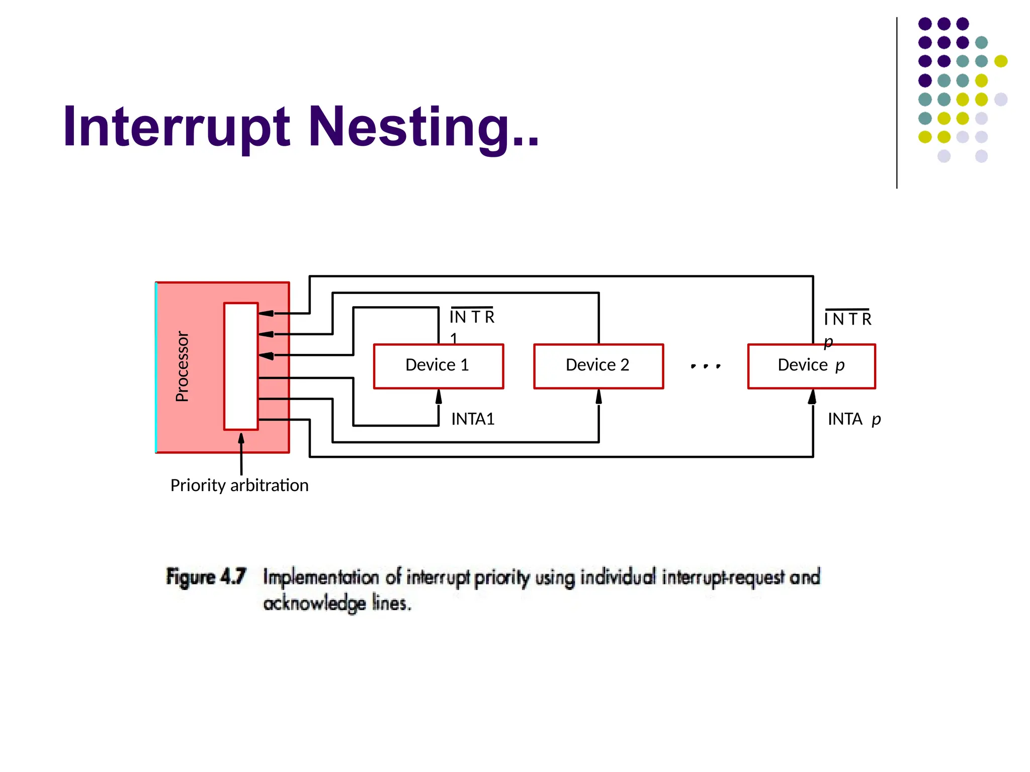
Interrupt Nesting..
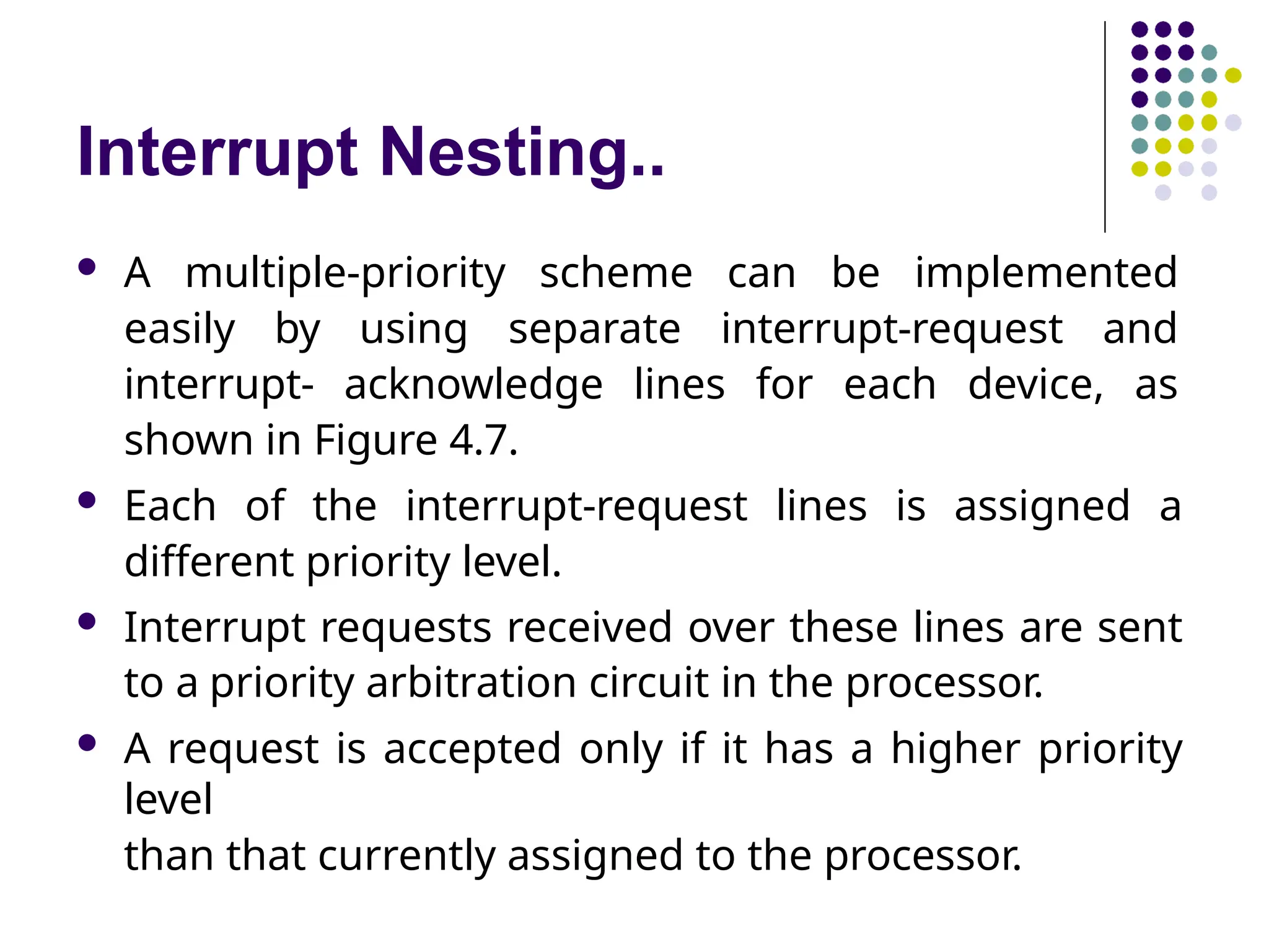
Amultiple-priority scheme can be implemented
easily by using separate interrupt-request and
interrupt- acknowledge lines for each device, as
shown in Figure 4.7.
Each of the interrupt-request lines is assigned a
different priority level.
Interrupt requests received over these lines are sent
to a priority arbitration circuit in the processor.
A request is accepted only if it has a higher priority
level
than that currently assigned to the processor.
Simultaneous Requests
Considerthe problem of simultaneous
arrivals of interrupt requests from two or
more devices.
The processor must have some means of deciding
which request to service first.
Using a priority scheme such as that of Figure 4.7,
the solution is straightforward.
The processor simply accepts the request having the
highest priority.
If several devices share one interrupt-request line,
as in Figure 4.6, some other mechanism is needed.
57.
Simultaneous Requests..
Polling scheme:
If the processor uses a polling mechanism to
poll the status registers of I/O devices to
determine which device is requesting an
interrupt.
In this case the priority is determined by
the order in which the devices are polled.
The first device with status bit set to 1 is
the device whose interrupt request is
accepted.
58.
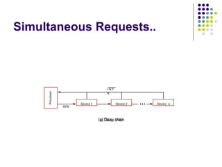
Simultaneous Requests..
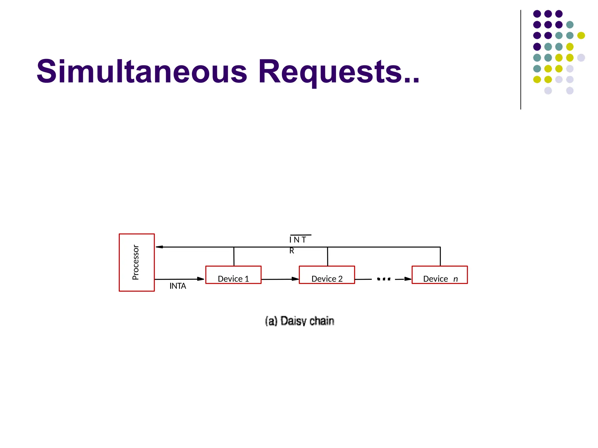
Daisy chainscheme:
Devices are connected to form a daisy chain.
The interrupt-request line INTR is common to all devices
Interrupt-acknowledge line INTA is connected in a daisy-
chain fashion.
When devices raise an interrupt request, the interrupt-
request line
INTR is activated.
The processor responds by setting INTA line to 1
This signal is received by device 1; if device 1 does not
need service, it passes the signal to device 2.
If device 1 has a pending request for interrupt, it blocks
the INTA
signal and proceeds to put its identifying code on the
data lines.
Simultaneous Requests..
WhenI/O devices were organized into a priority
structure, each device had its own interrupt-request
and interrupt-acknowledge line.
When I/O devices were organized in a daisy chain
fashion, the devices shared an interrupt-request line,
and the interrupt-acknowledge propagated through
the devices.
A combination of priority structure and daisy chain
scheme can also used.
61.
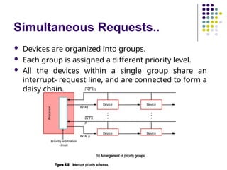
Simultaneous Requests..
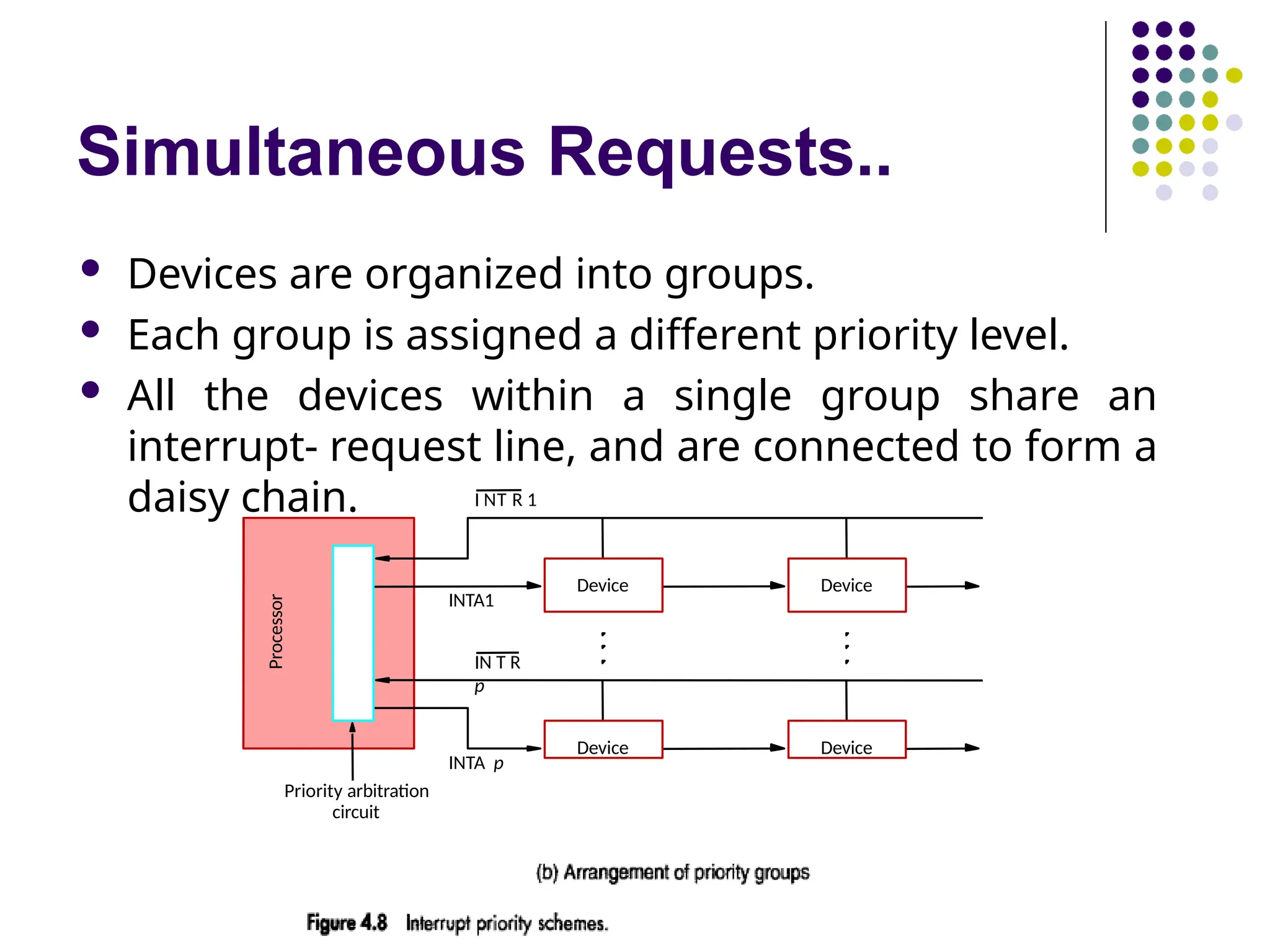
Devicesare organized into groups.
Each group is assigned a different priority level.
All the devices within a single group share an
interrupt- request line, and are connected to form a
daisy chain.
Device Device
Priority arbitration
circuit
Processor
Device Device
I NT R 1
IN T R
p
INTA1
INTA p
62.
Controlling Device Requests
Only those devices that are being used in a program
should
be allowed to generate interrupt requests.
To control which devices are allowed to generate
interrupt requests, the interface circuit of each I/O
device has an interrupt-enable bit.
If the interrupt-enable bit in the device interface is set
to 1, then the device is allowed to generate an
interrupt-request.
Interrupt-enable bit in the device’s interface circuit
determines whether the device is allowed to generate an
interrupt request.
Interrupt-enable bit in the processor status register or
the priority structure of the interrupts determines
63.
Controlling Device Requests..
For example, keyboard interrupt-enable, KEN,
and display interrupt-enable, DEN, flags in
register CONTROL in Figure 4.3.
If either of these flags is set, the interface circuit
generates an interrupt request whenever the
corresponding status flag in register STATUS is
set.
At the same time, the interface circuit sets bit
KIRQ or DIRQ to indicate that the keyboard or
display unit, respectively, is requesting an
interrupt.
If an interrupt-enable bit is equal to 0, the interface
circuit will not generate an interrupt request,
64.
Controlling Device Requests..
To summarize, there are two independent
mechanisms for controlling interrupt
requests:
At the device end, an interrupt-enable bit in a
control register determines whether the
device is allowed to generate an interrupt
request.
At the processor end, either an interrupt
enable bit in the PS register or a priority
structure determines whether a given
interrupt request will be accepted.
65.
Example
Consider aprocessor that uses the vectored
interrupt scheme, where the starting address of
the interrupt- service routine is stored at memory
location INTVEC.
Interrupts are enabled by setting to 1 an interrupt-
enable bit, IE, in the processor status word, which we
assume is bit 9.
A keyboard and a display unit connected to this
processor have the status, control, and data
registers shown in Figure 4.3.
Assume that at some point in a program called Main
we wish to read an input line from the keyboard and
store the characters in successive byte locations in
66.
Example..
To performthis operation using interrupts, we
need to initialize the interrupt process, as follows:
1. Load the starting address of the interrupt-service
routine
in location INTVEC.
2. Load the address LINE in a memory location
PNTR. The interrupt-service routine will use this
location as a pointer to store the input characters
in the memory.
3. Enable keyboard interrupts by setting bit 2 in
register
CONTROL to 1.
4. Enable interrupts in the processor by setting to 1
67.
Example..
Once thisinitialization is completed, typing a
character on the keyboard will cause an
interrupt request to be generated by the
keyboard interface.
The program being executed at that time will
be interrupted and the interrupt-service
routine will be executed.
68.
Example..
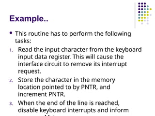
This routinehas to perform the following
tasks:
1. Read the input character from the keyboard
input data register. This will cause the
interface circuit to remove its interrupt
request.
2. Store the character in the memory
location pointed to by PNTR, and
increment PNTR.
3. When the end of the line is reached,
disable keyboard interrupts and inform
69.
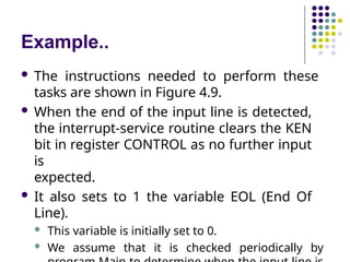
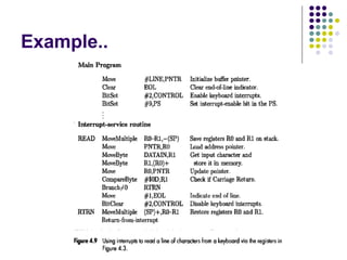
Example..
The instructionsneeded to perform these
tasks are shown in Figure 4.9.
When the end of the input line is detected,
the interrupt-service routine clears the KEN
bit in register CONTROL as no further input
is
expected.
It also sets to 1 the variable EOL (End Of
Line).
This variable is initially set to 0.
We assume that it is checked periodically by
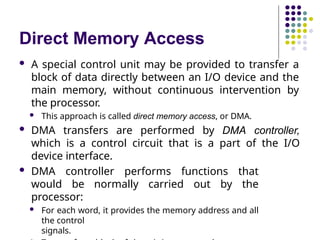
Direct Memory Access
A special control unit may be provided to transfer a
block of data directly between an I/O device and the
main memory, without continuous intervention by
the processor.
This approach is called direct memory access, or DMA.
DMA transfers are performed by DMA controller,
which is a control circuit that is a part of the I/O
device interface.
DMA controller performs functions that
would be normally carried out by the
processor:
For each word, it provides the memory address and all
the control
signals.
73.
Direct Memory Access..
DMA controller can transfer a block of data from an
external device to the processor, without any
intervention from the processor.
However, the operation of the DMA controller must be
under the control of a program executed by the processor.
That is, the processor must initiate the DMA transfer.
To initiate the DMA transfer, the processor informs the
DMA controller of:
Starting address,
Number of words in the block.
Direction of transfer (I/O device to the memory, or memory to
the I/O
device).
Once the DMA controller completes the DMA transfer, it
informs the processor by raising an interrupt signal.
74.
Direct Memory Access..
While a DMA transfer is taking place, the program
that requested the transfer cannot continue, and
the processor can be used to execute another
program.
After the DMA transfer is completed, the processor can
return
to the program that requested the transfer.
For an I/O operation involving DMA, the OS puts the
program that requested the transfer in the Blocked
state, initiates the DMA operation, and starts the
execution of another program.
When the transfer is completed, the DMA controller
informs the processor by sending an interrupt request.
In response, the OS puts the suspended program in the
Direct Memory Access..
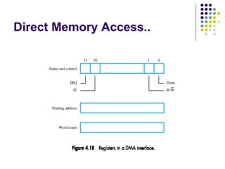
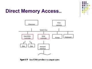
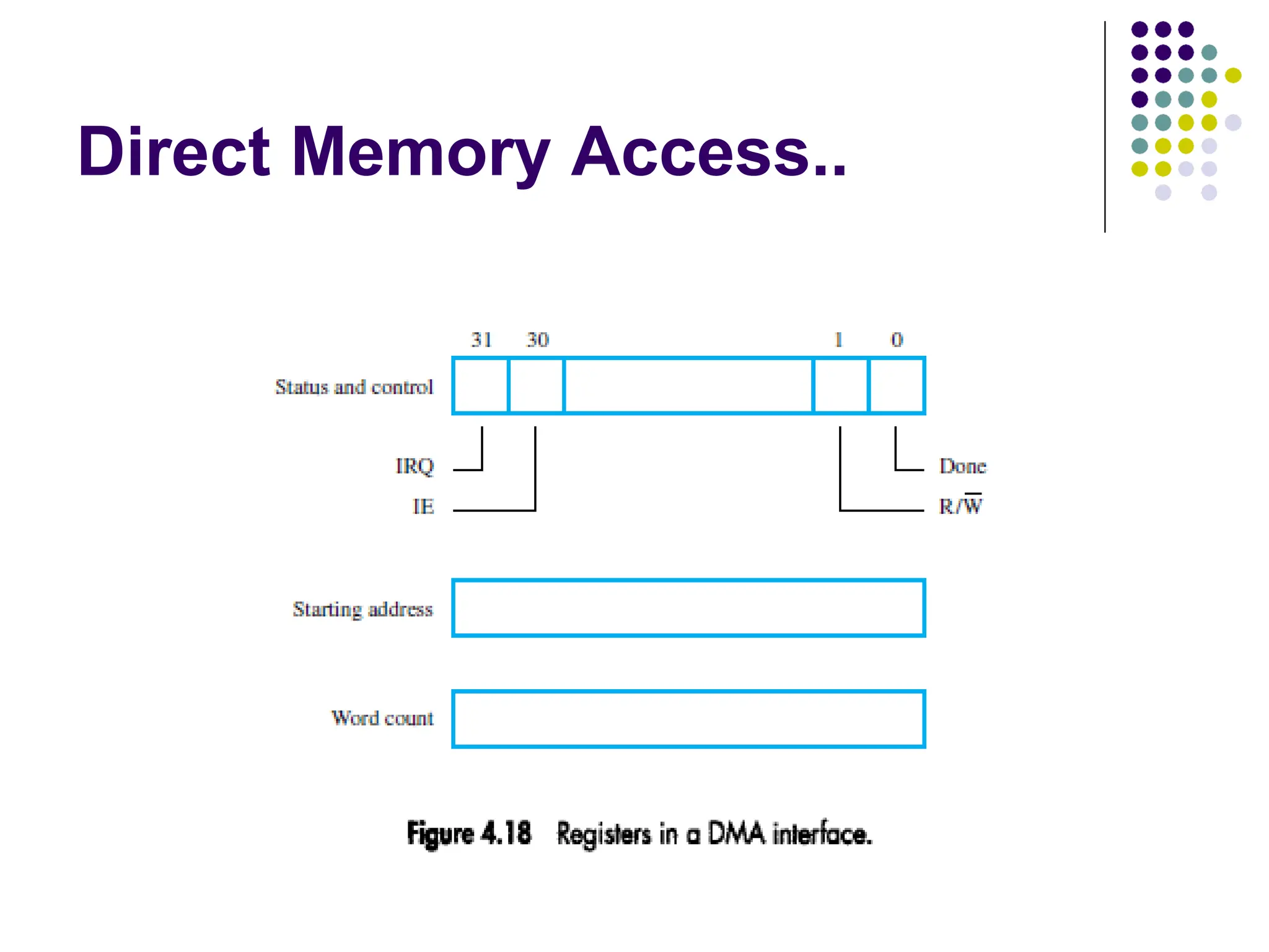
Figure 4.18 shows an example of the DMA
controller registers that are accessed by the
processor to initiate transfer operations.
Two registers are used for storing the starting
address
and the word count.
The third register contains status and control
flags.
The R
/
Wഥ bit determines the direction of the
transfer.
When this bit is set to 1 by a program instruction, the
controller
performs a read operation.
77.
Direct Memory Access..
When the controller has completed transferring a
block of data and is ready to receive another
command, it sets the Done flag to 1.
Bit 30 is the Interrupt-enable flag, IE.
When this flag is set to 1, it causes the controller to raise
an
interrupt after it has completed transferring a block of data.
Finally, the controller sets the IRQ bit to 1 when it
has
requested an interrupt.
78.
Direct Memory Access..
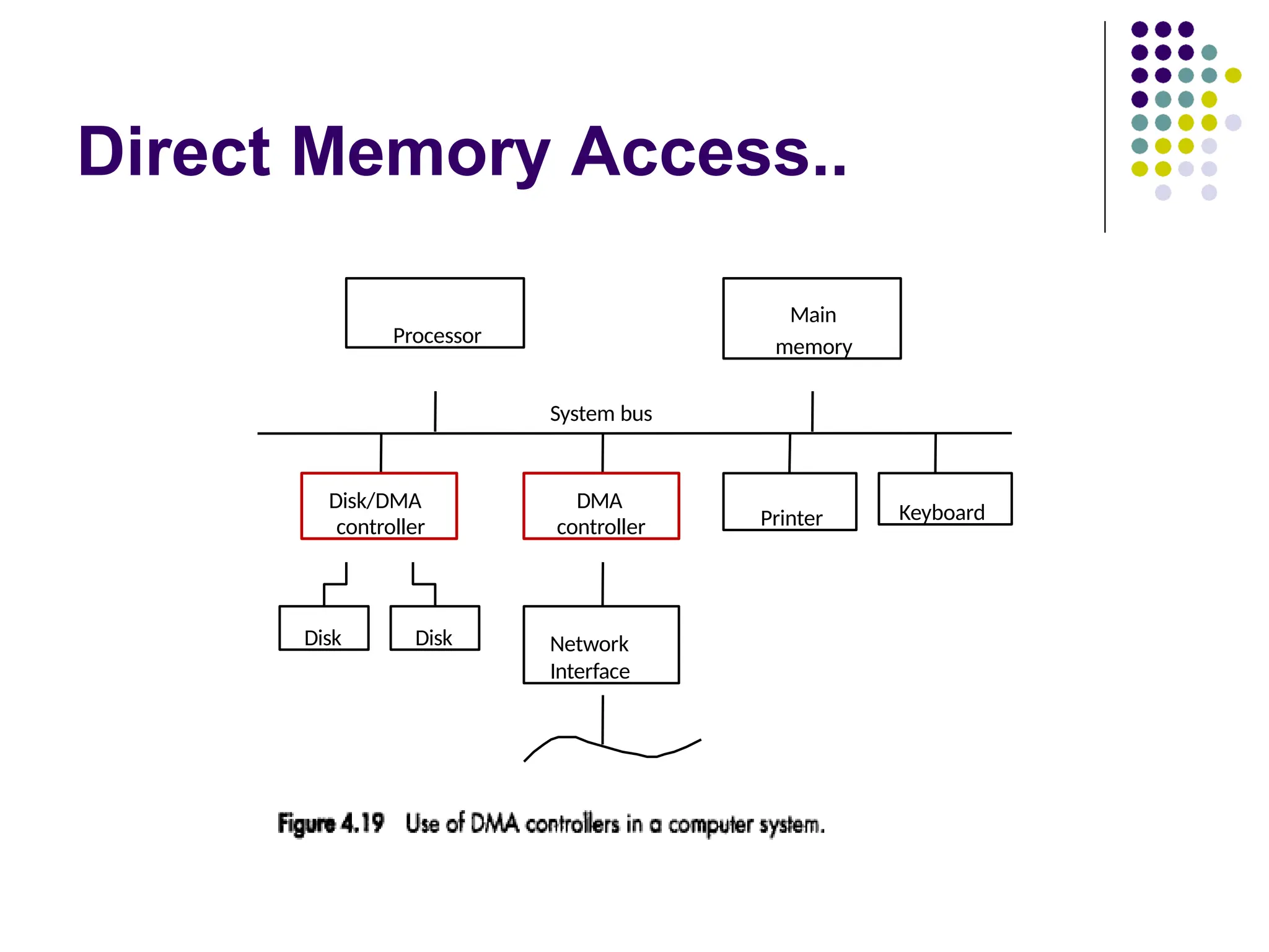
An example of a computer system is given in
Figure 4.19, showing how DMA controllers may
be used.
DMA controller connects a high-speed
network to the computer bus.
Disk controller, which controls two disks also
has DMA capability.
It provides two DMA channels.
It can perform two independent DMA
operations, as if each disk has its own DMA
controller.
The registers to store the memory address,
word count and status and control
Direct Memory Access..
To start a DMA transfer of a block of data from the main
memory to
one of the disks, a program writes the address and word count
information into the registers of the corresponding channel
of the disk controller.
It also provides the disk controller with information to
identify the
data for future retrieval.
The DMA controller proceeds independently to
implement the specified operation.
When the DMA transfer is completed, this fact is recorded in
the status and control register of the DMA channel by setting
the Done bit.
At the same time, if the IE bit is set, the controller sends an
interrupt request to the processor and sets the IRQ bit.
81.
Direct Memory Access..
Processor and DMA controllers have to use the bus in an
interwoven
fashion to access the memory.
DMA devices are given higher priority than the processor to access
the bus.
Among different DMA devices, high priority is given to high-speed
peripherals such as a disk or a graphics display device.
Processor originates most memory access cycles on the bus.
DMA controller can be said to “steal” memory access cycles from
the
bus.
This interweaving technique is called “cycle stealing”.
An alternate approach is the provide a DMA controller an
exclusive capability to initiate transfers on the bus, and hence
exclusive access to the main memory.
This is known as the block or burst mode.
82.
Direct Memory Access..
Most DMA controllers incorporate a data storage buffer.
In the case of the network interface in Figure 4.19, for
example, the DMA controller reads a block of data from the
main memory and stores it into its input buffer.
This transfer takes place using burst mode at a
speed appropriate to the memory and the
computer bus.
Then, the data in the buffer are transmitted over
the network at
the speed of the network.
A conflict may arise if both the processor and a DMA
controller or two DMA controllers try to use the bus at the
same time to access the main memory.
To resolve these conflicts, an arbitration procedure is
implemented on the bus to coordinate the activities of all