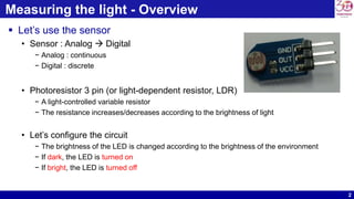
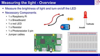
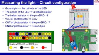
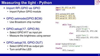
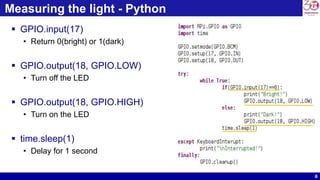
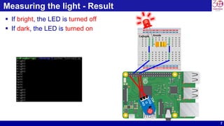
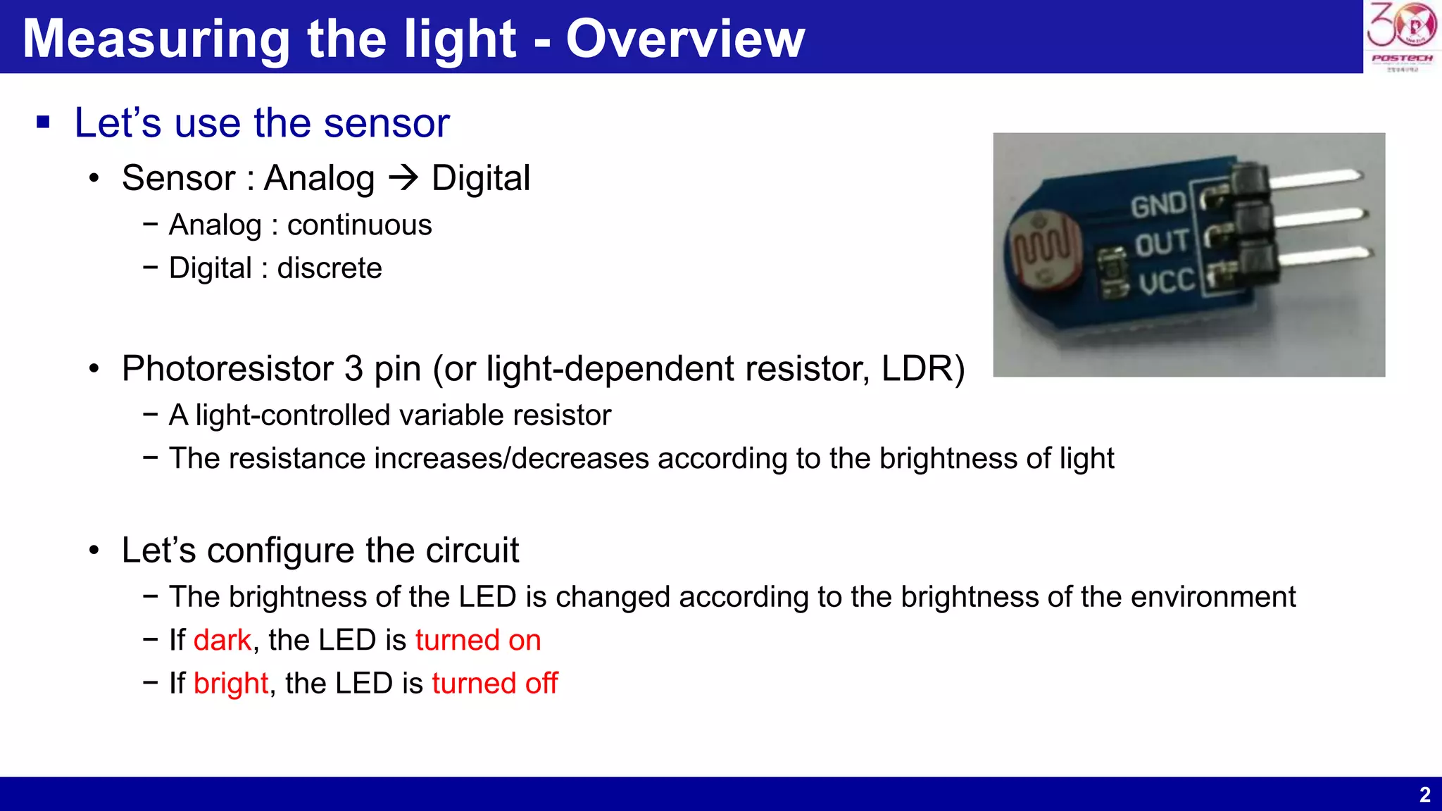
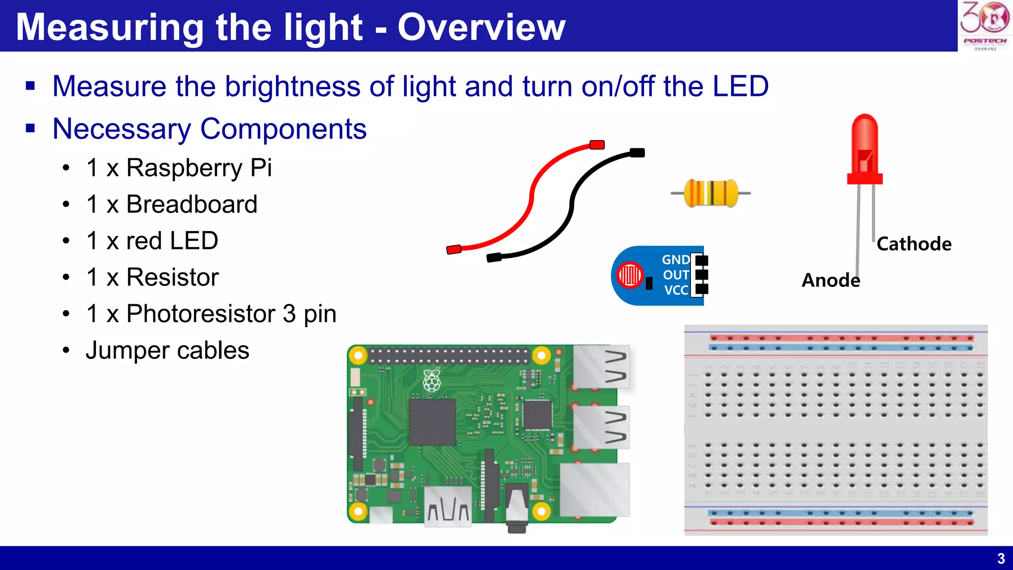
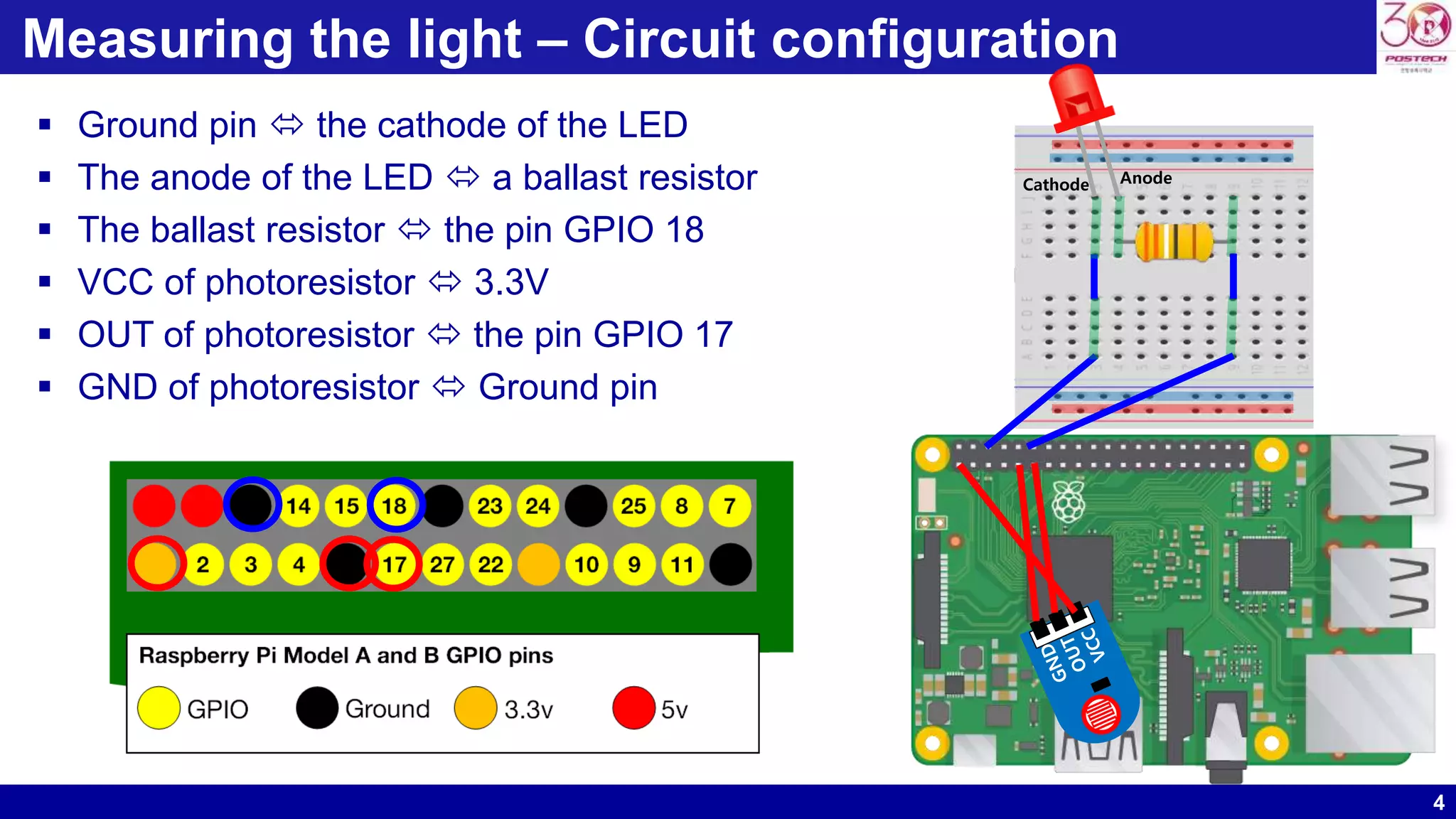
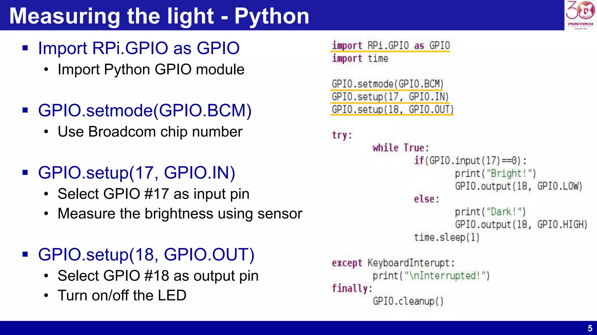
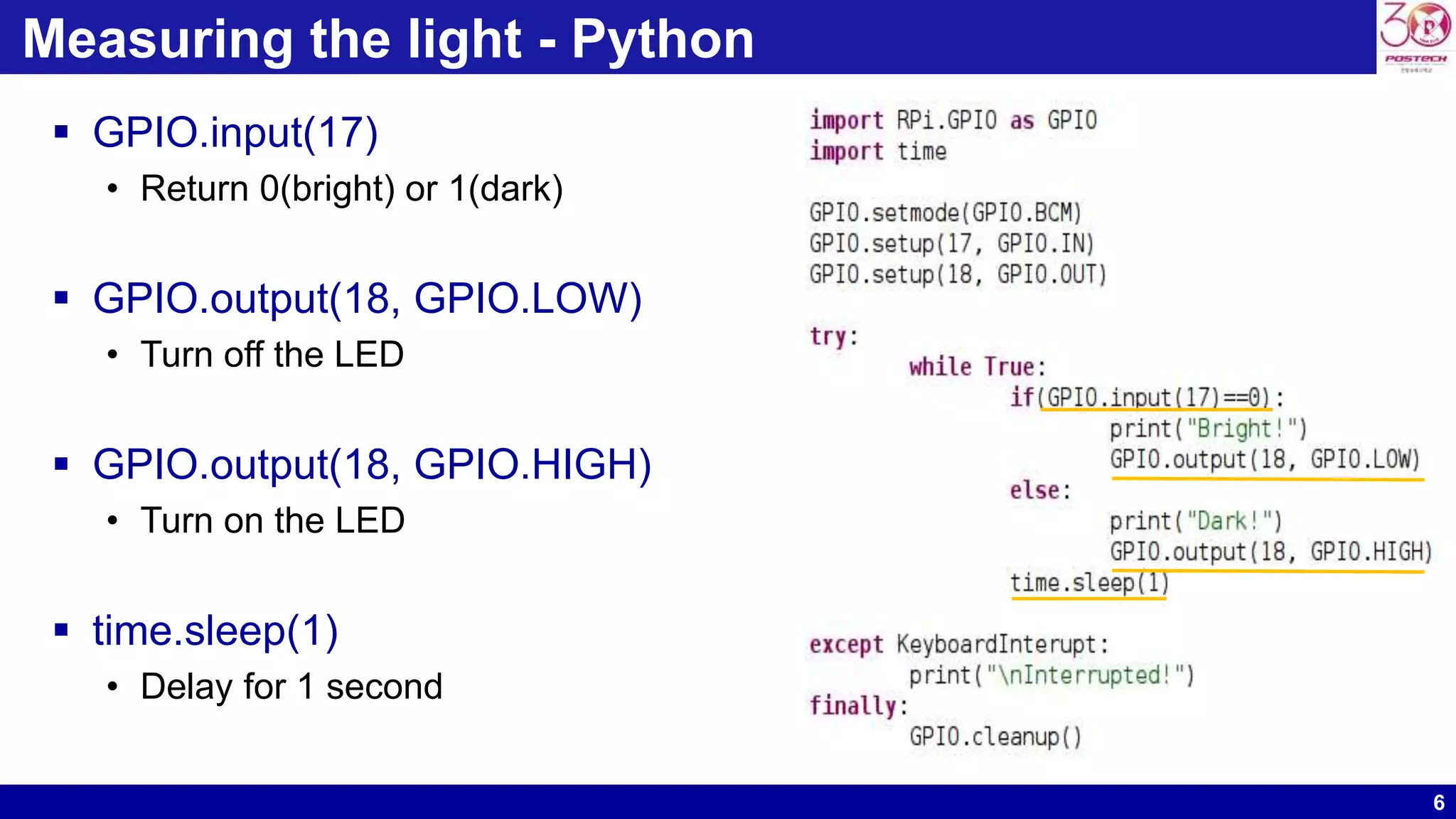
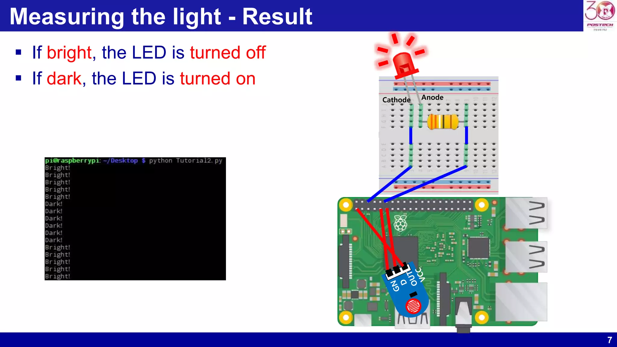
KEMBAR78
Raspberry pi tutorial #2 | PPTX
1
Raspberry Pi Tutorial #2
- Measuring the light -
Dong Ho Son
POSTECH
Pohang, Korea
donghoson@postech.ac.kr
2
Measuring the light - Overview
 Let’s use the sensor
• Sensor : Analog  Digital
− Analog : continuous
− Digital : discrete
• Photoresistor 3 pin (or light-dependent resistor, LDR)
− A light-controlled variable resistor
− The resistance increases/decreases according to the brightness of light
• Let’s configure the circuit
− The brightness of the LED is changed according to the brightness of the environment
− If dark, the LED is turned on
− If bright, the LED is turned off
3
Measuring the light - Overview
 Measure the brightness of light and turn on/off the LED
 Necessary Components
• 1 x Raspberry Pi
• 1 x Breadboard
• 1 x red LED
• 1 x Resistor
• 1 x Photoresistor 3 pin
• Jumper cables
Anode
Cathode
GND
OUT
VCC
4
Measuring the light – Circuit configuration
 Ground pin  the cathode of the LED
 The anode of the LED  a ballast resistor
 The ballast resistor  the pin GPIO 18
 VCC of photoresistor  3.3V
 OUT of photoresistor  the pin GPIO 17
 GND of photoresistor  Ground pin
Cathode Anode
5
Measuring the light - Python
 Import RPi.GPIO as GPIO
• Import Python GPIO module
 GPIO.setmode(GPIO.BCM)
• Use Broadcom chip number
 GPIO.setup(17, GPIO.IN)
• Select GPIO #17 as input pin
• Measure the brightness using sensor
 GPIO.setup(18, GPIO.OUT)
• Select GPIO #18 as output pin
• Turn on/off the LED
6
Measuring the light - Python
 GPIO.input(17)
• Return 0(bright) or 1(dark)
 GPIO.output(18, GPIO.LOW)
• Turn off the LED
 GPIO.output(18, GPIO.HIGH)
• Turn on the LED
 time.sleep(1)
• Delay for 1 second
7
Measuring the light - Result
 If bright, the LED is turned off
 If dark, the LED is turned on
Cathode Anode

Raspberry pi tutorial #2

  • 1.
    1 Raspberry Pi Tutorial#2 - Measuring the light - Dong Ho Son POSTECH Pohang, Korea donghoson@postech.ac.kr
  • 2.
    2 Measuring the light- Overview  Let’s use the sensor • Sensor : Analog  Digital − Analog : continuous − Digital : discrete • Photoresistor 3 pin (or light-dependent resistor, LDR) − A light-controlled variable resistor − The resistance increases/decreases according to the brightness of light • Let’s configure the circuit − The brightness of the LED is changed according to the brightness of the environment − If dark, the LED is turned on − If bright, the LED is turned off
  • 3.
    3 Measuring the light- Overview  Measure the brightness of light and turn on/off the LED  Necessary Components • 1 x Raspberry Pi • 1 x Breadboard • 1 x red LED • 1 x Resistor • 1 x Photoresistor 3 pin • Jumper cables Anode Cathode GND OUT VCC
  • 4.
    4 Measuring the light– Circuit configuration  Ground pin  the cathode of the LED  The anode of the LED  a ballast resistor  The ballast resistor  the pin GPIO 18  VCC of photoresistor  3.3V  OUT of photoresistor  the pin GPIO 17  GND of photoresistor  Ground pin Cathode Anode
  • 5.
    5 Measuring the light- Python  Import RPi.GPIO as GPIO • Import Python GPIO module  GPIO.setmode(GPIO.BCM) • Use Broadcom chip number  GPIO.setup(17, GPIO.IN) • Select GPIO #17 as input pin • Measure the brightness using sensor  GPIO.setup(18, GPIO.OUT) • Select GPIO #18 as output pin • Turn on/off the LED
  • 6.
    6 Measuring the light- Python  GPIO.input(17) • Return 0(bright) or 1(dark)  GPIO.output(18, GPIO.LOW) • Turn off the LED  GPIO.output(18, GPIO.HIGH) • Turn on the LED  time.sleep(1) • Delay for 1 second
  • 7.
    7 Measuring the light- Result  If bright, the LED is turned off  If dark, the LED is turned on Cathode Anode