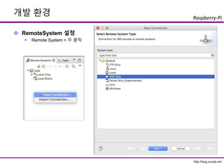
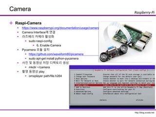
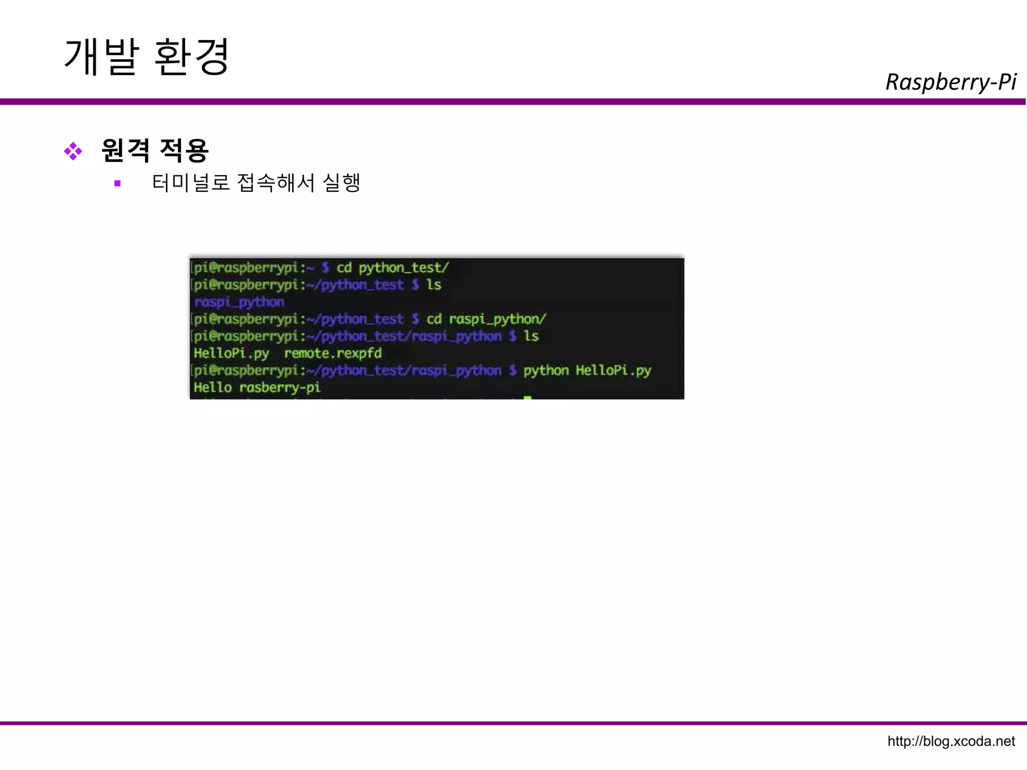
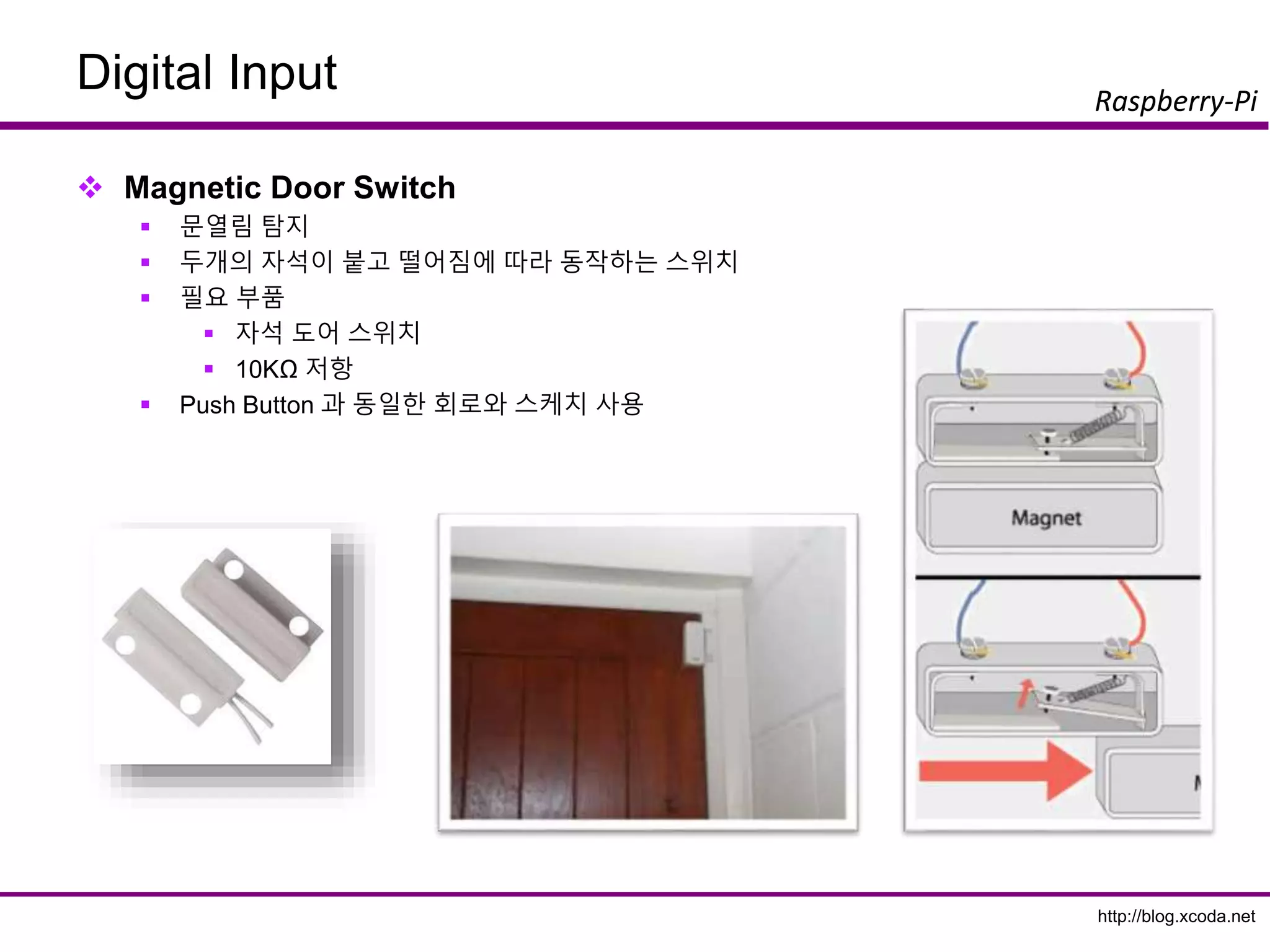
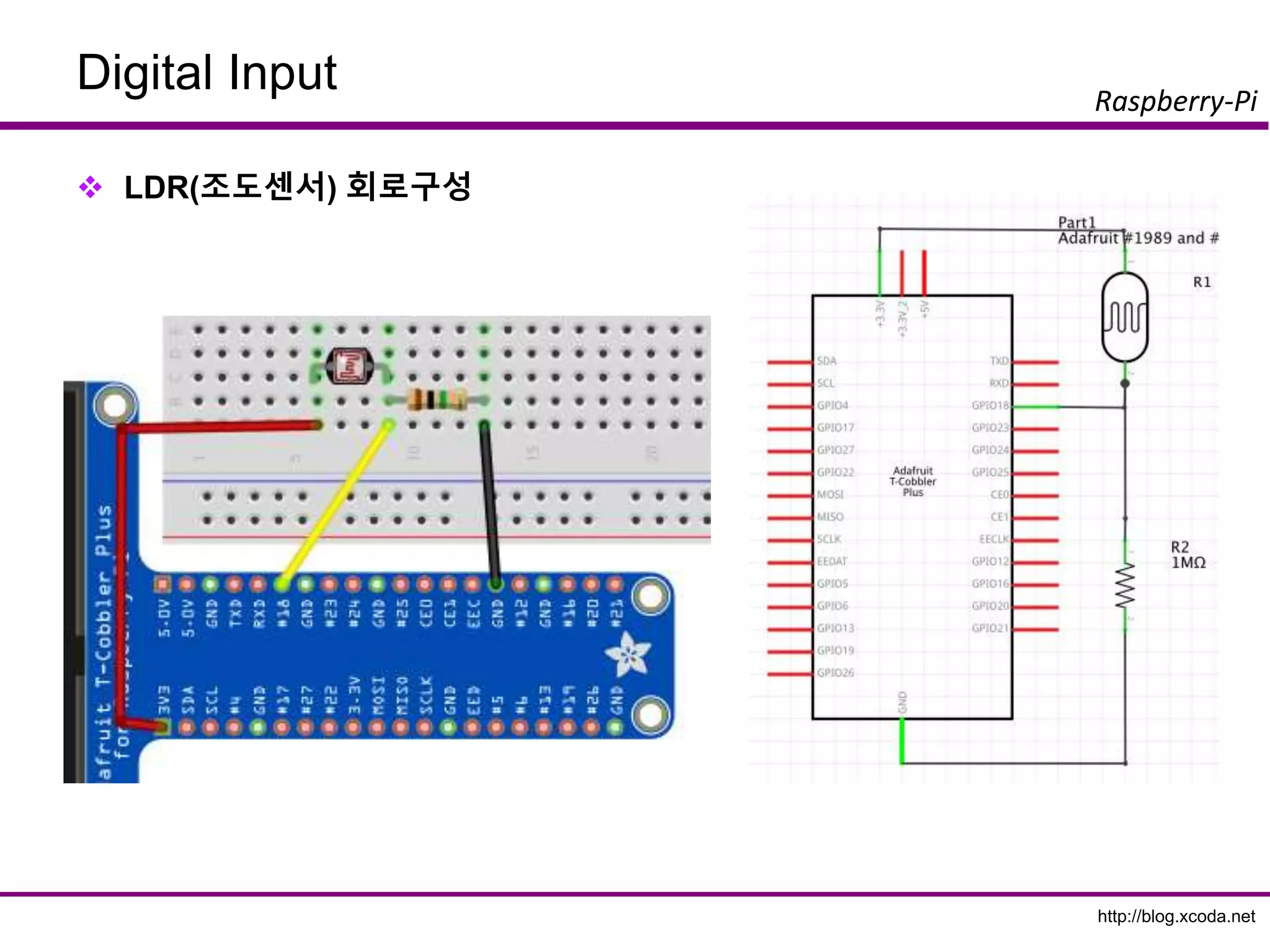
The slide that explains how to make circuits that connected to Raspberry PI GPIO and several sensors.
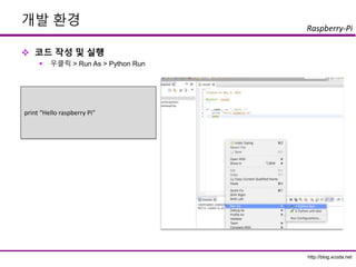
This slides show how to program using Python language.
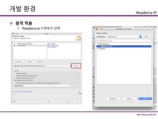
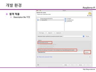
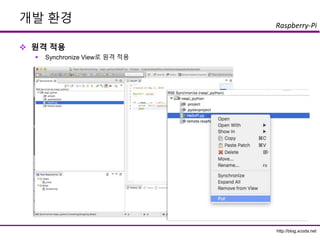
http://blog.xcoda.net
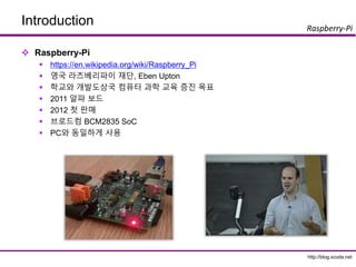
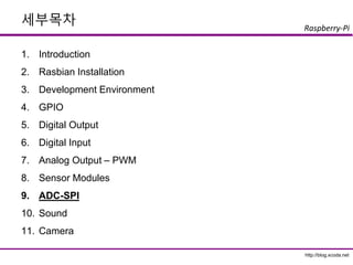
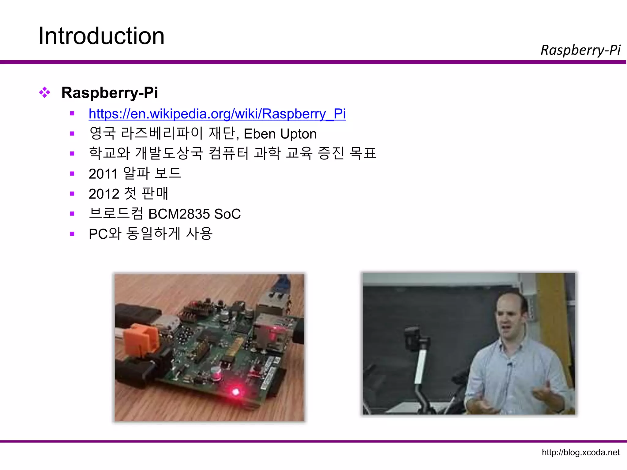
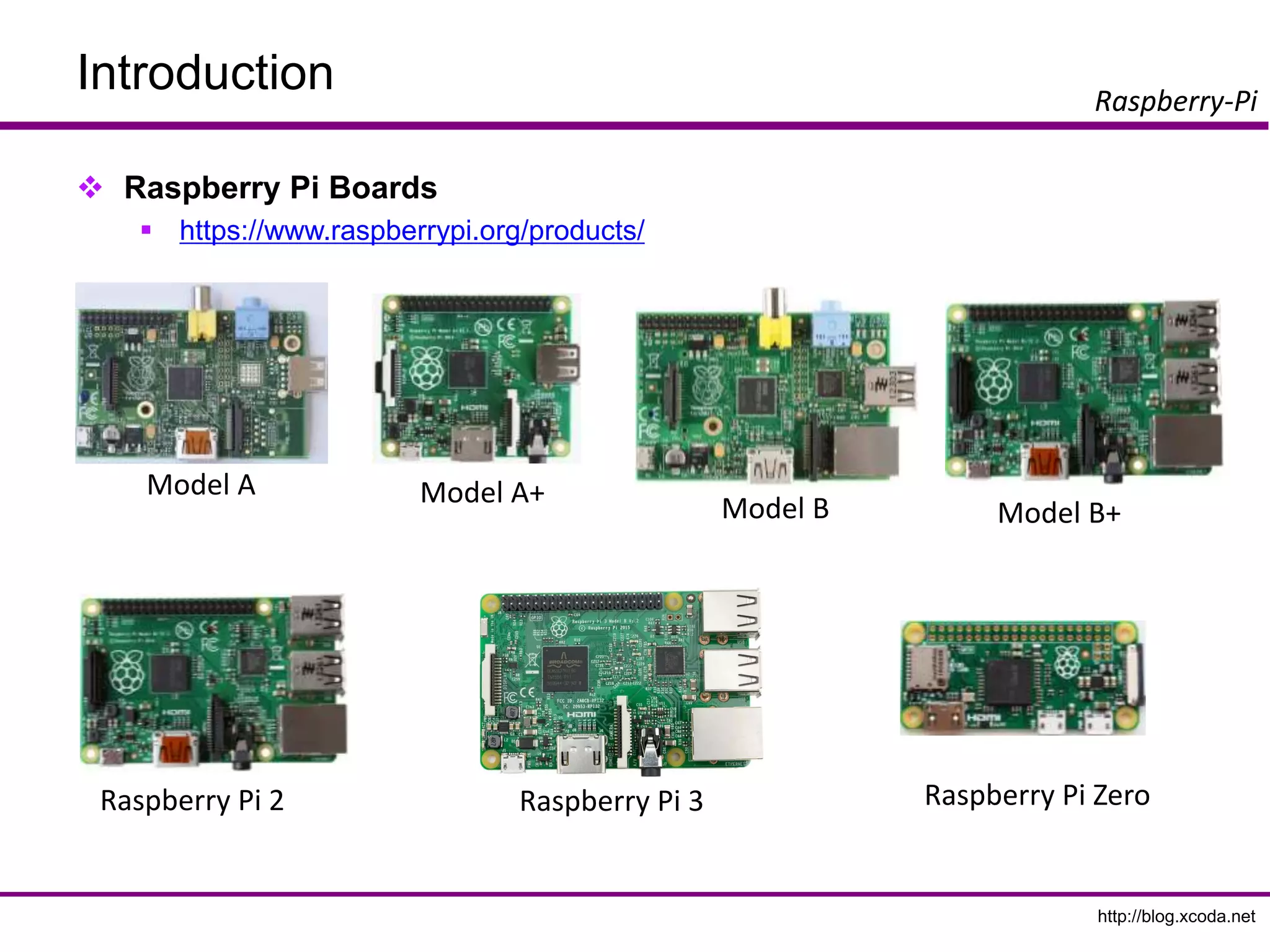
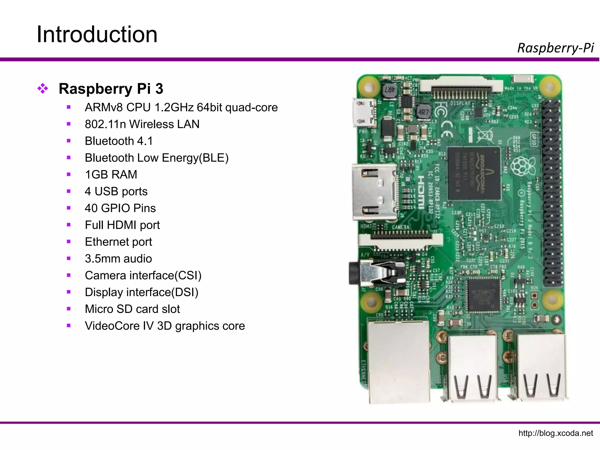
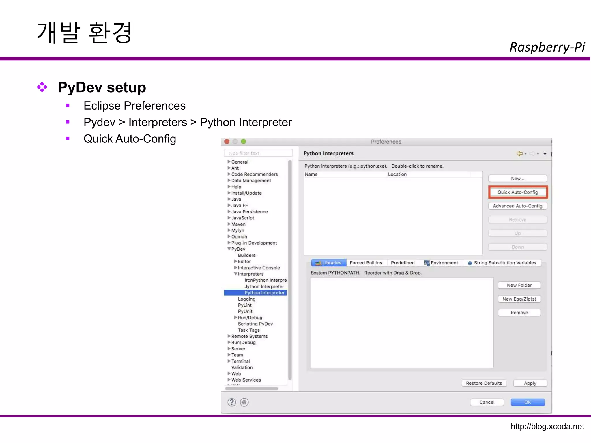
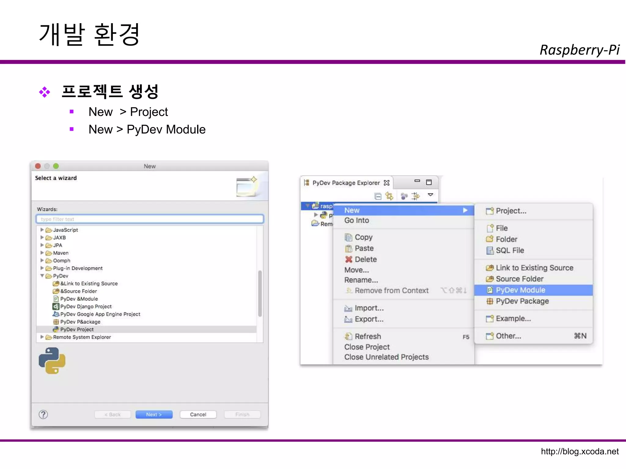
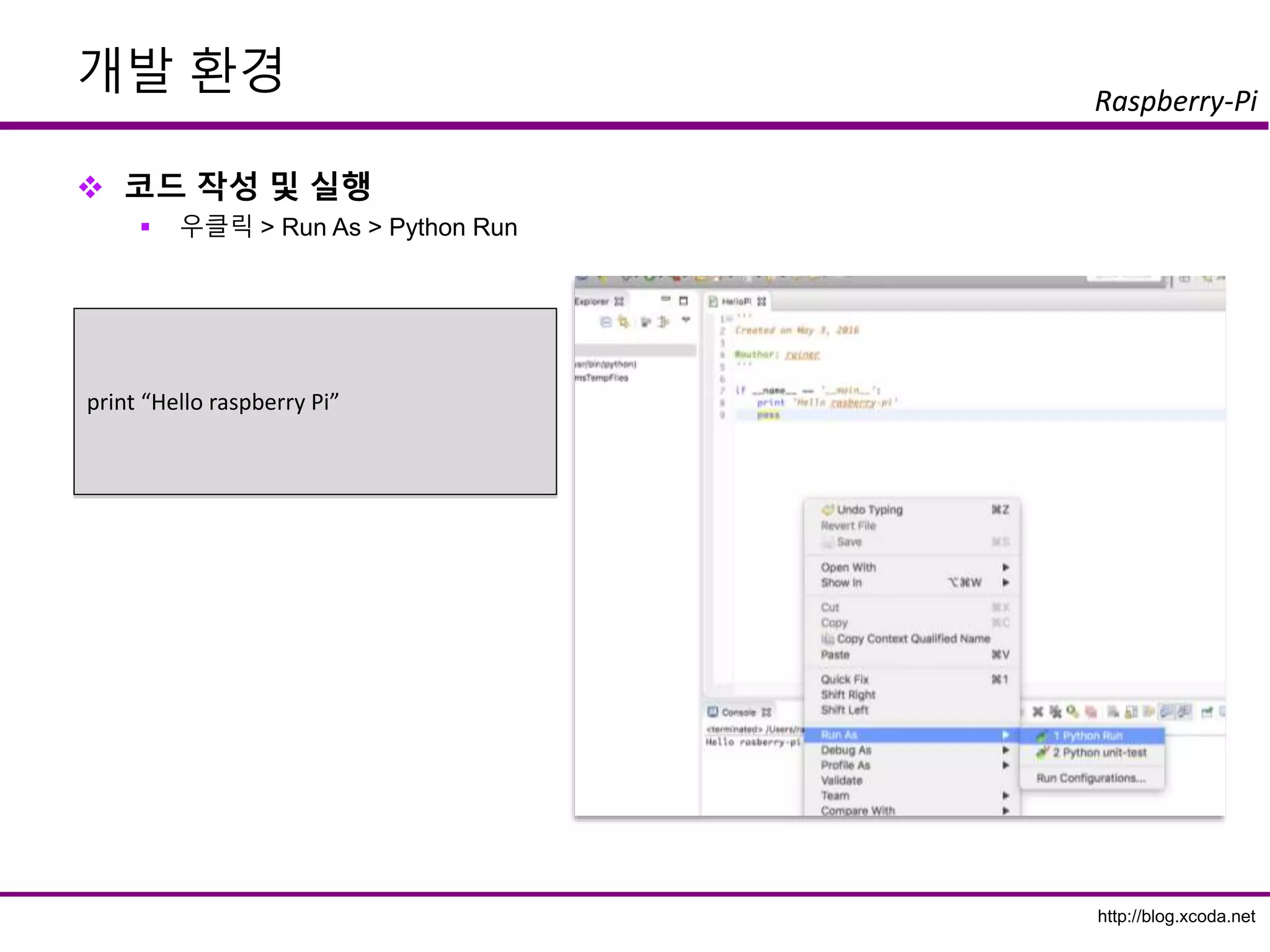
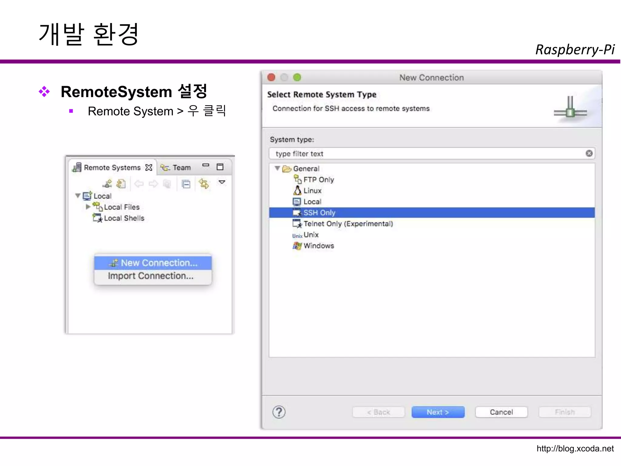
Raspberry-Pi
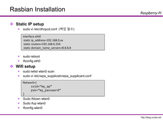
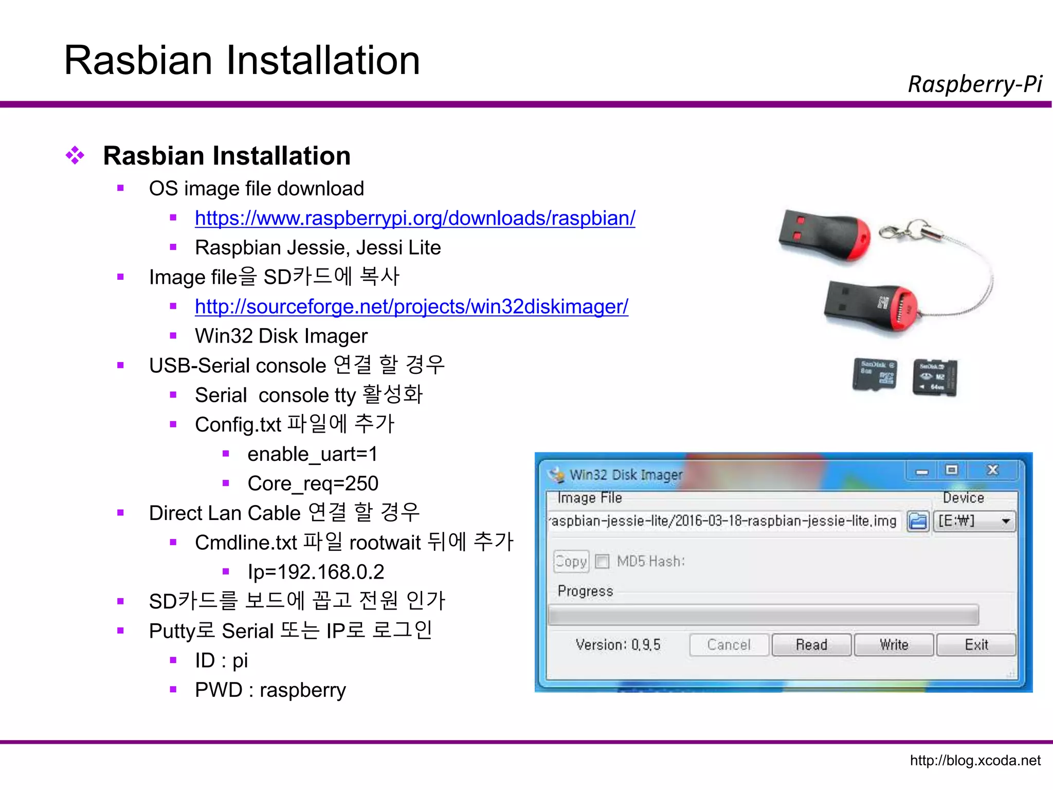
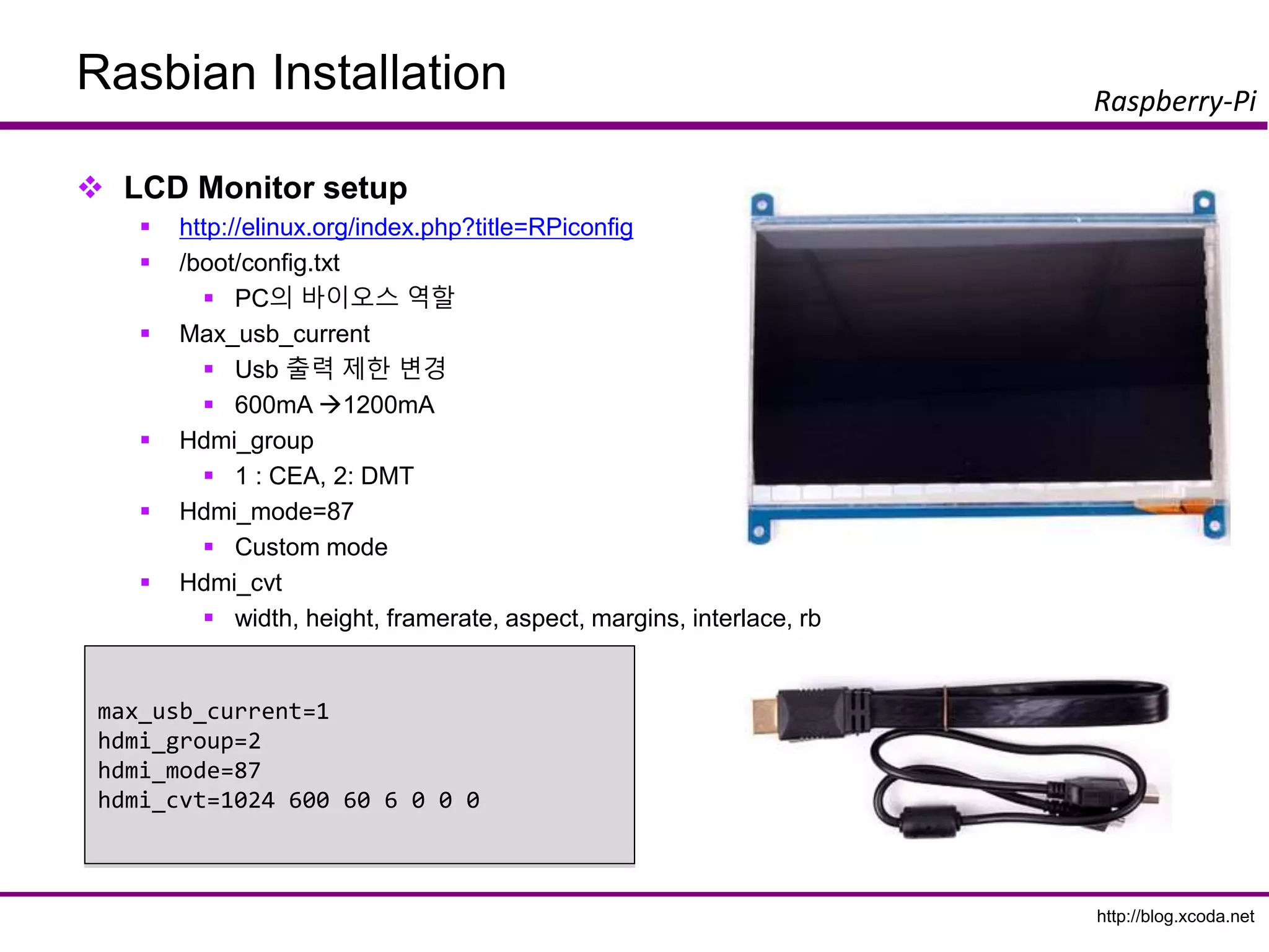
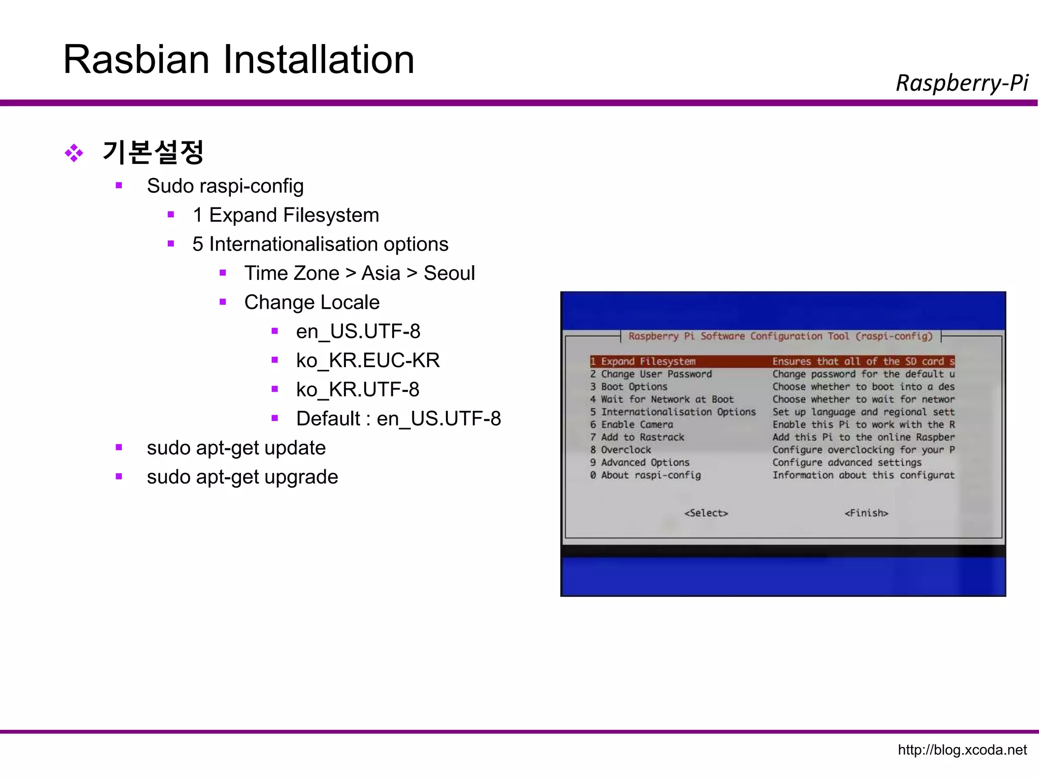
Rasbian Installation
RasbianInstallation
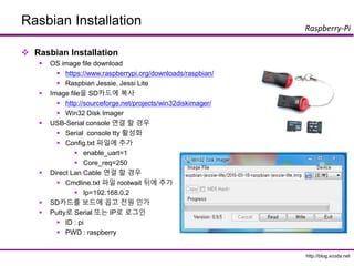
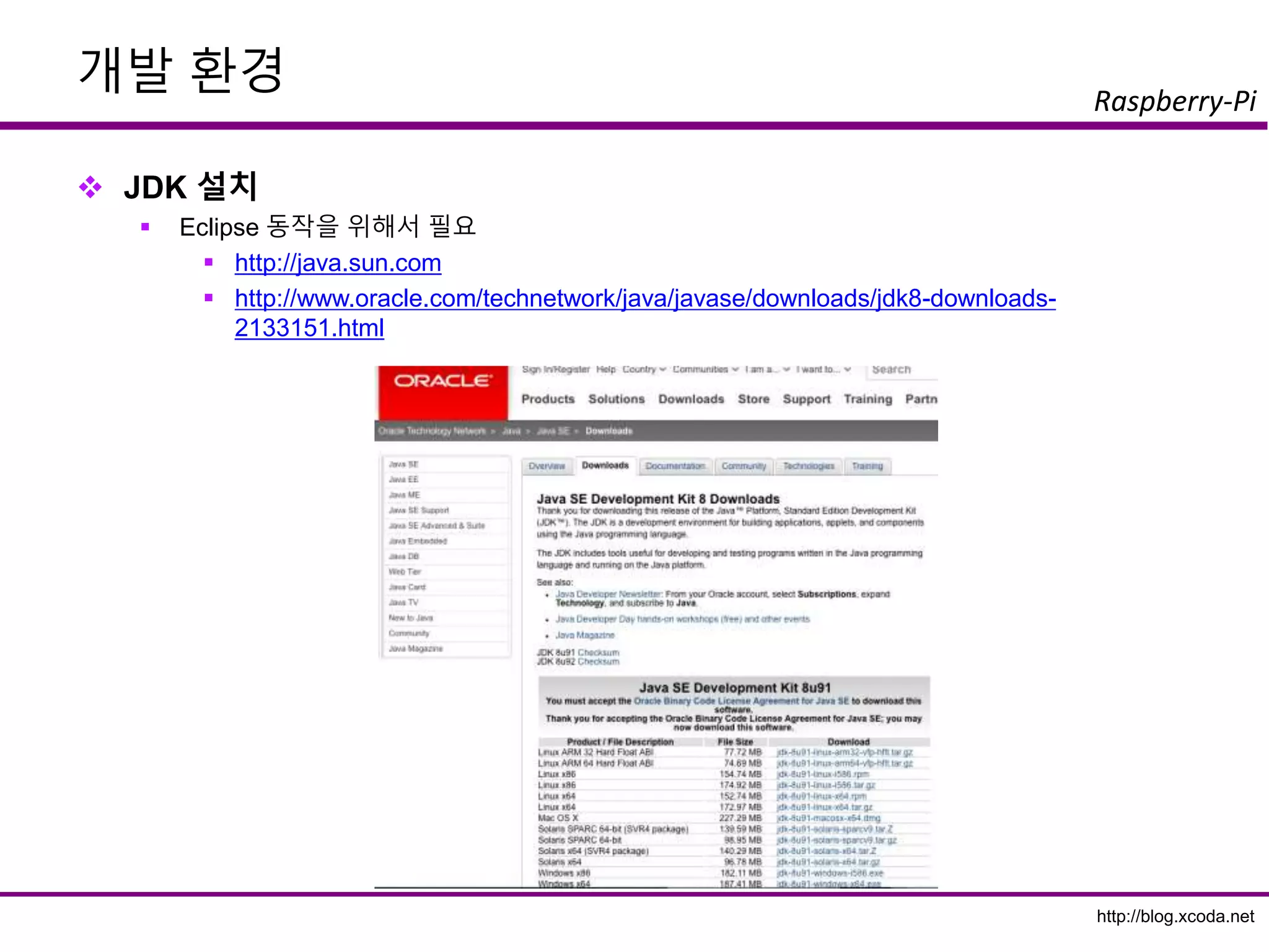
OS image file download
https://www.raspberrypi.org/downloads/raspbian/
Raspbian Jessie, Jessi Lite
Image file을 SD카드에 복사
http://sourceforge.net/projects/win32diskimager/
Win32 Disk Imager
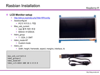
USB-Serial console 연결 할 경우
Serial console tty 활성화
Config.txt 파일에 추가
enable_uart=1
Core_req=250
Direct Lan Cable 연결 할 경우
Cmdline.txt 파일 rootwait 뒤에 추가
Ip=192.168.0.2
SD카드를 보드에 꼽고 전원 인가
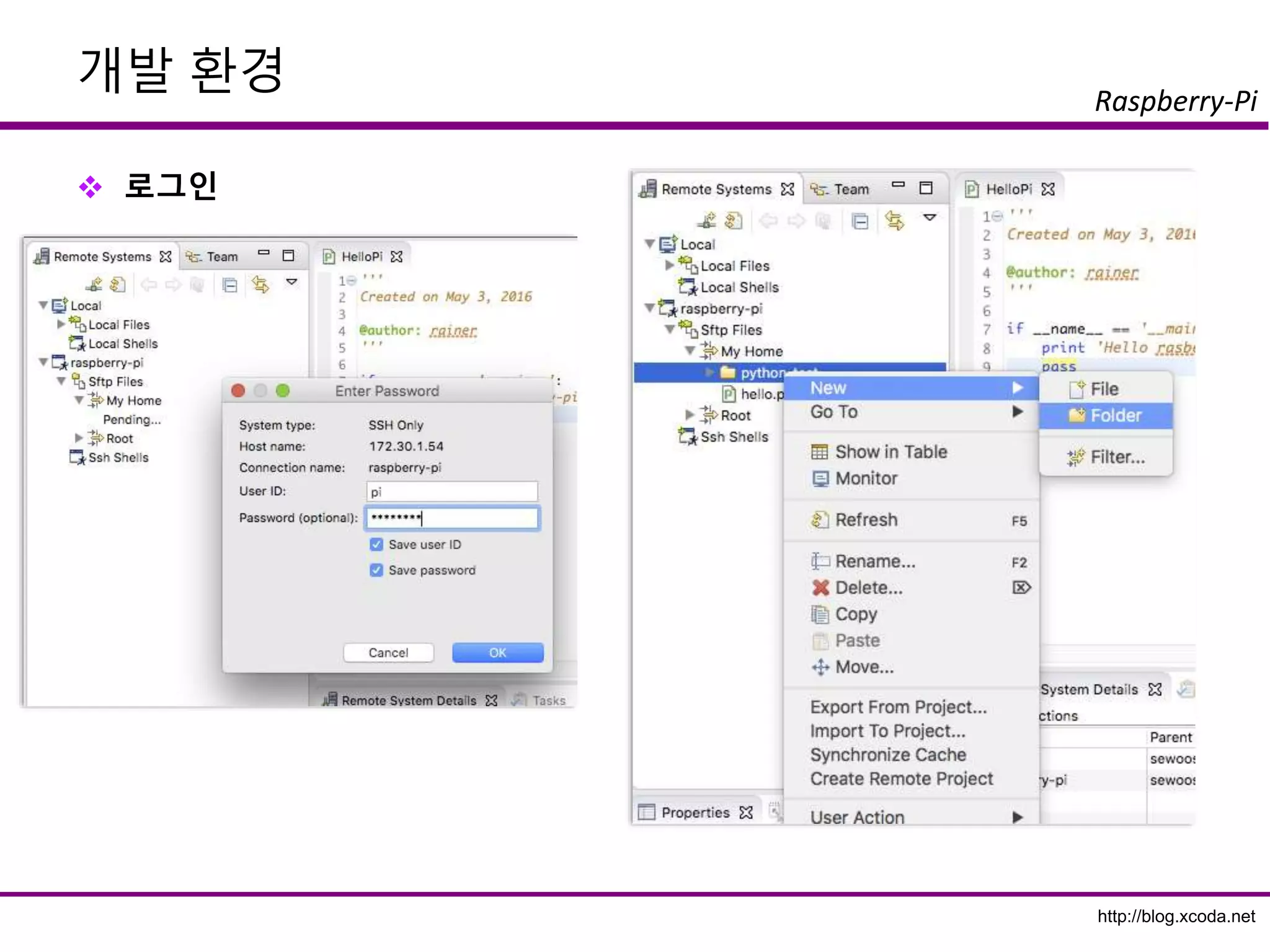
Putty로 Serial 또는 IP로 로그인
ID : pi
PWD : raspberry
http://blog.xcoda.net
Raspberry-Pi
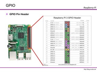
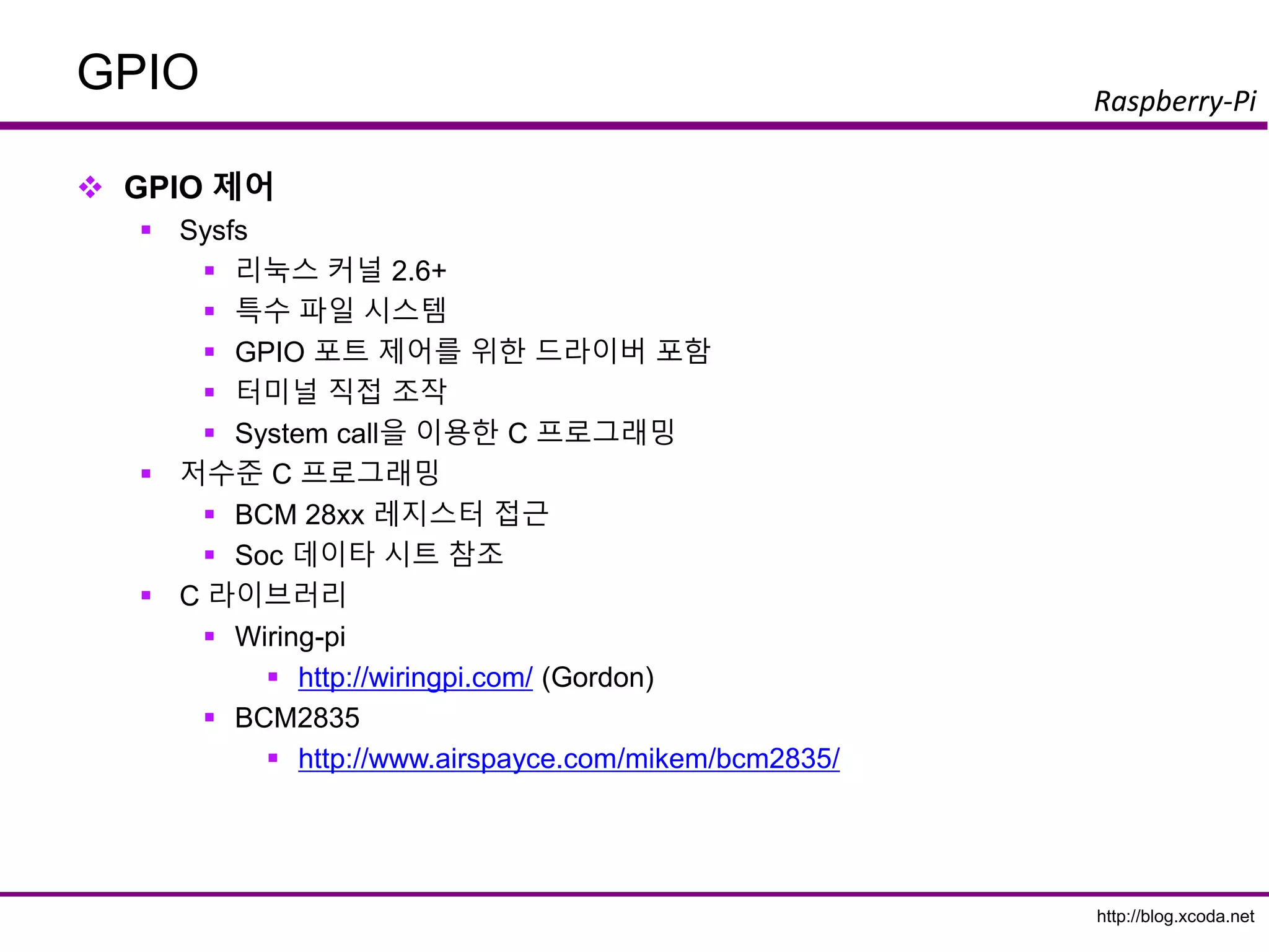
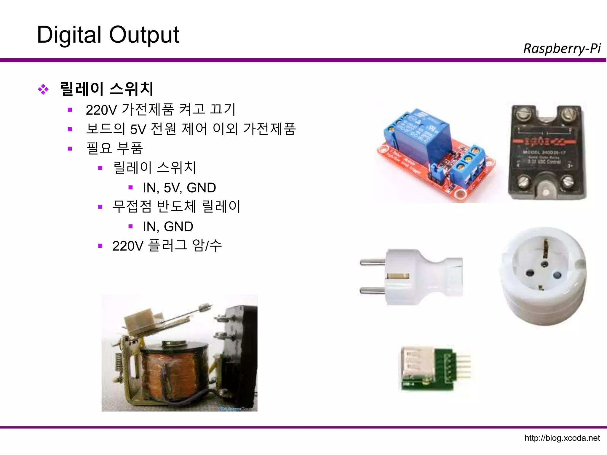
GPIO
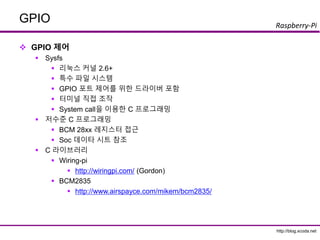
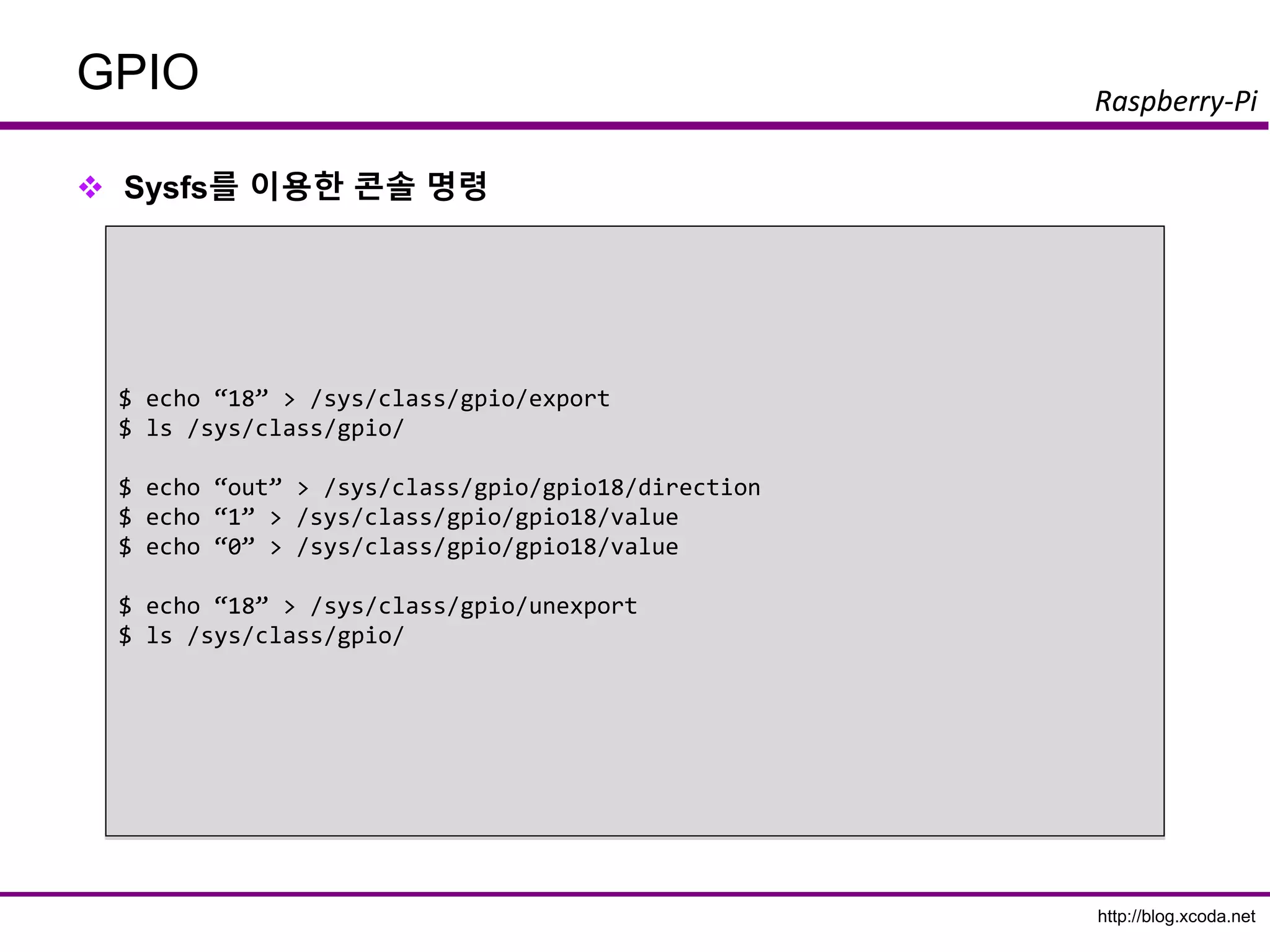
GPIO 제어
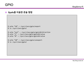
Sysfs
리눅스 커널 2.6+
특수 파일 시스템
GPIO 포트 제어를 위한 드라이버 포함
터미널 직접 조작
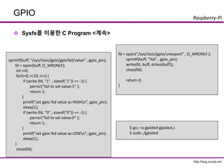
System call을 이용한 C 프로그래밍
저수준 C 프로그래밍
BCM 28xx 레지스터 접근
Soc 데이타 시트 참조
C 라이브러리
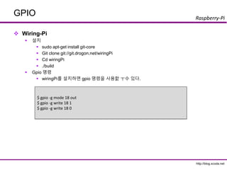
Wiring-pi
http://wiringpi.com/ (Gordon)
BCM2835
http://www.airspayce.com/mikem/bcm2835/
30.
http://blog.xcoda.net
Raspberry-Pi
GPIO
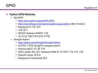
Python GPIOModules
Rpi.GPIO
https://pypi.python.org/pypi/RPi.GPIO
https://sourceforge.net/projects/raspberry-gpio-python/ (Ben Croston)
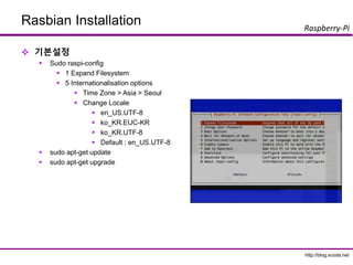
Raspberry Pi 기본 설치
사용 용이
GPIO와 Software PWM만 지원
실시간성 어플리케이션에 부적합
WiringPi-Python
https://github.com/WiringPi/WiringPi-Python
C언어로 구현된 WringPi의 wrapped version
Arduino style의 코드를 지원
GPIO, Serial, SPI, I2C, Hardware PWM 등 하드웨어 기능 모두 사용
WriginPi Library 종속성
Raspberry-Pi build/install 필요
http://blog.xcoda.net
Raspberry-Pi
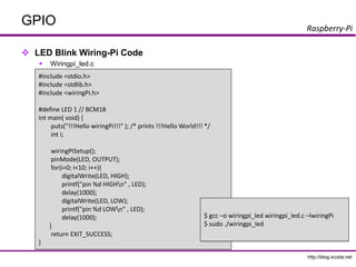
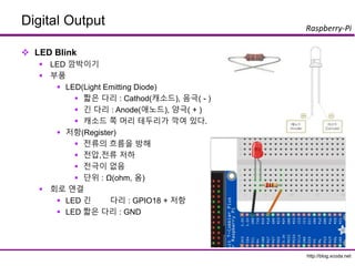
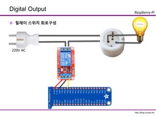
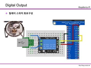
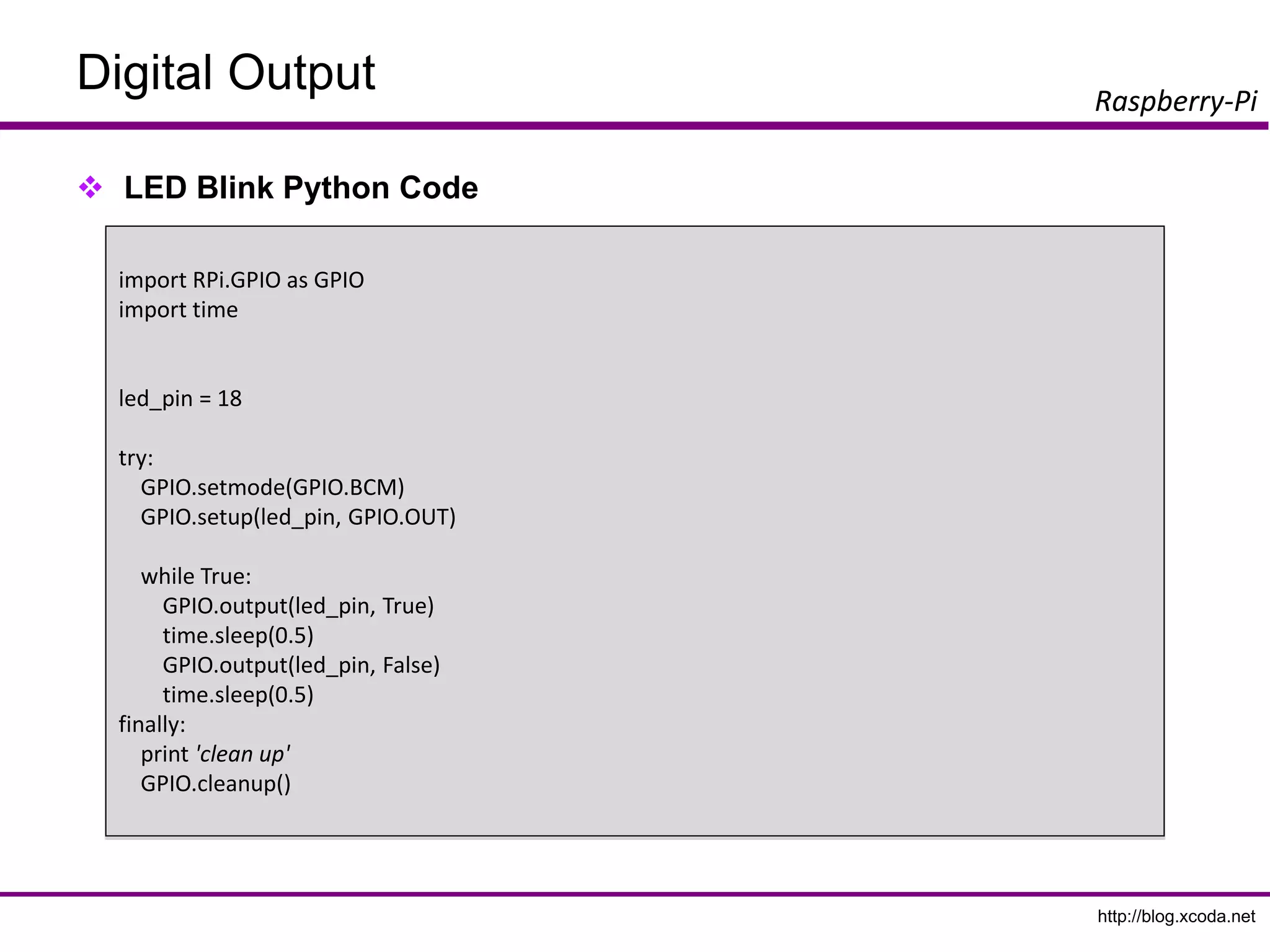
Digital Output
LEDBlink
LED 깜박이기
부품
LED(Light Emitting Diode)
짧은 다리 : Cathod(캐소드), 음극( - )
긴 다리 : Anode(애노드), 양극( + )
캐소드 쪽 머리 테두리가 깍여 있다.
저항(Register)
전류의 흐름을 방해
전압,전류 저하
전극이 없음
단위 : Ω(ohm, 옴)
회로 연결
LED 긴 다리 : GPIO18 + 저항
LED 짧은 다리 : GND
39.
http://blog.xcoda.net
Raspberry-Pi
Digital Output
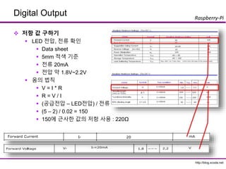
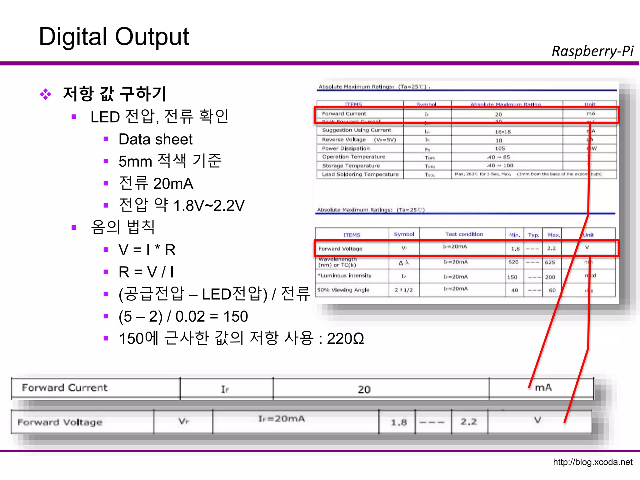
저항값 구하기
LED 전압, 전류 확인
Data sheet
5mm 적색 기준
전류 20mA
전압 약 1.8V~2.2V
옴의 법칙
V = I * R
R = V / I
(공급전압 – LED전압) / 전류
(5 – 2) / 0.02 = 150
150에 근사한 값의 저항 사용 : 220Ω
40.
http://blog.xcoda.net
Raspberry-Pi
Digital Output
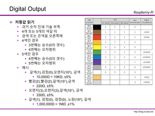
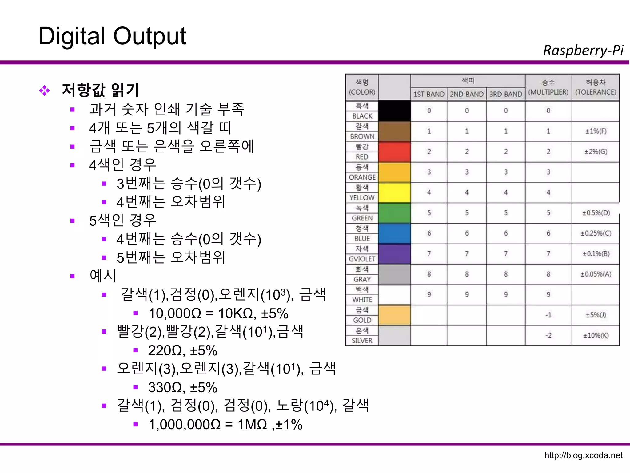
저항값읽기
과거 숫자 인쇄 기술 부족
4개 또는 5개의 색갈 띠
금색 또는 은색을 오른쪽에
4색인 경우
3번째는 승수(0의 갯수)
4번째는 오차범위
5색인 경우
4번째는 승수(0의 갯수)
5번째는 오차범위
예시
갈색(1),검정(0),오렌지(103), 금색
10,000Ω = 10KΩ, ±5%
빨강(2),빨강(2),갈색(101),금색
220Ω, ±5%
오렌지(3),오렌지(3),갈색(101), 금색
330Ω, ±5%
갈색(1), 검정(0), 검정(0), 노랑(104), 갈색
1,000,000Ω = 1MΩ ,±1%
http://blog.xcoda.net
Raspberry-Pi
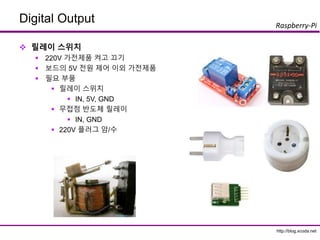
Digital Output
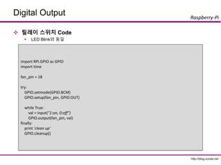
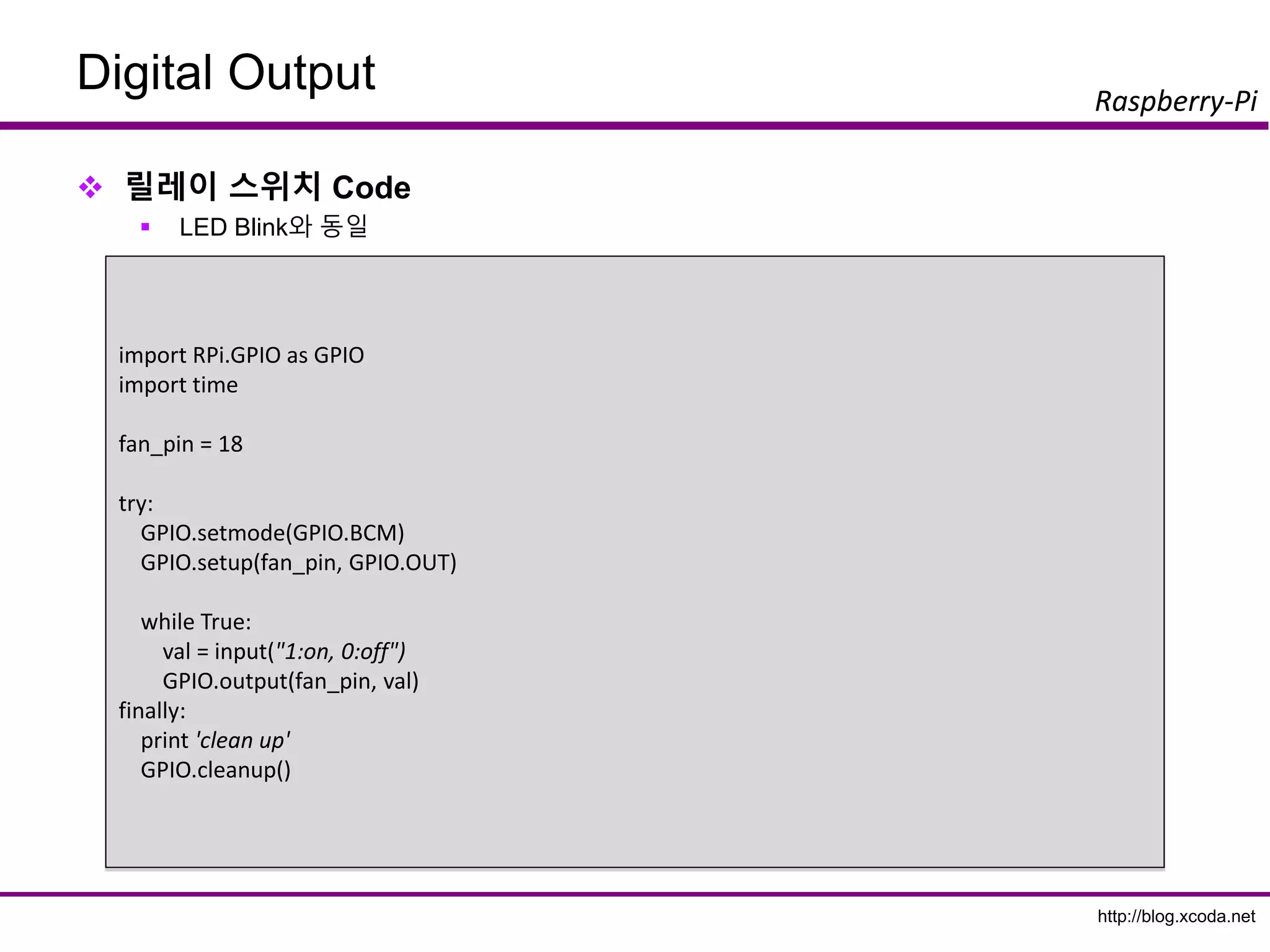
릴레이스위치 Code
LED Blink와 동일
import RPi.GPIO as GPIO
import time
fan_pin = 18
try:
GPIO.setmode(GPIO.BCM)
GPIO.setup(fan_pin, GPIO.OUT)
while True:
val = input("1:on, 0:off")
GPIO.output(fan_pin, val)
finally:
print 'clean up'
GPIO.cleanup()
48.
http://blog.xcoda.net
Raspberry-Pi
Digital Output
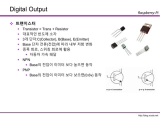
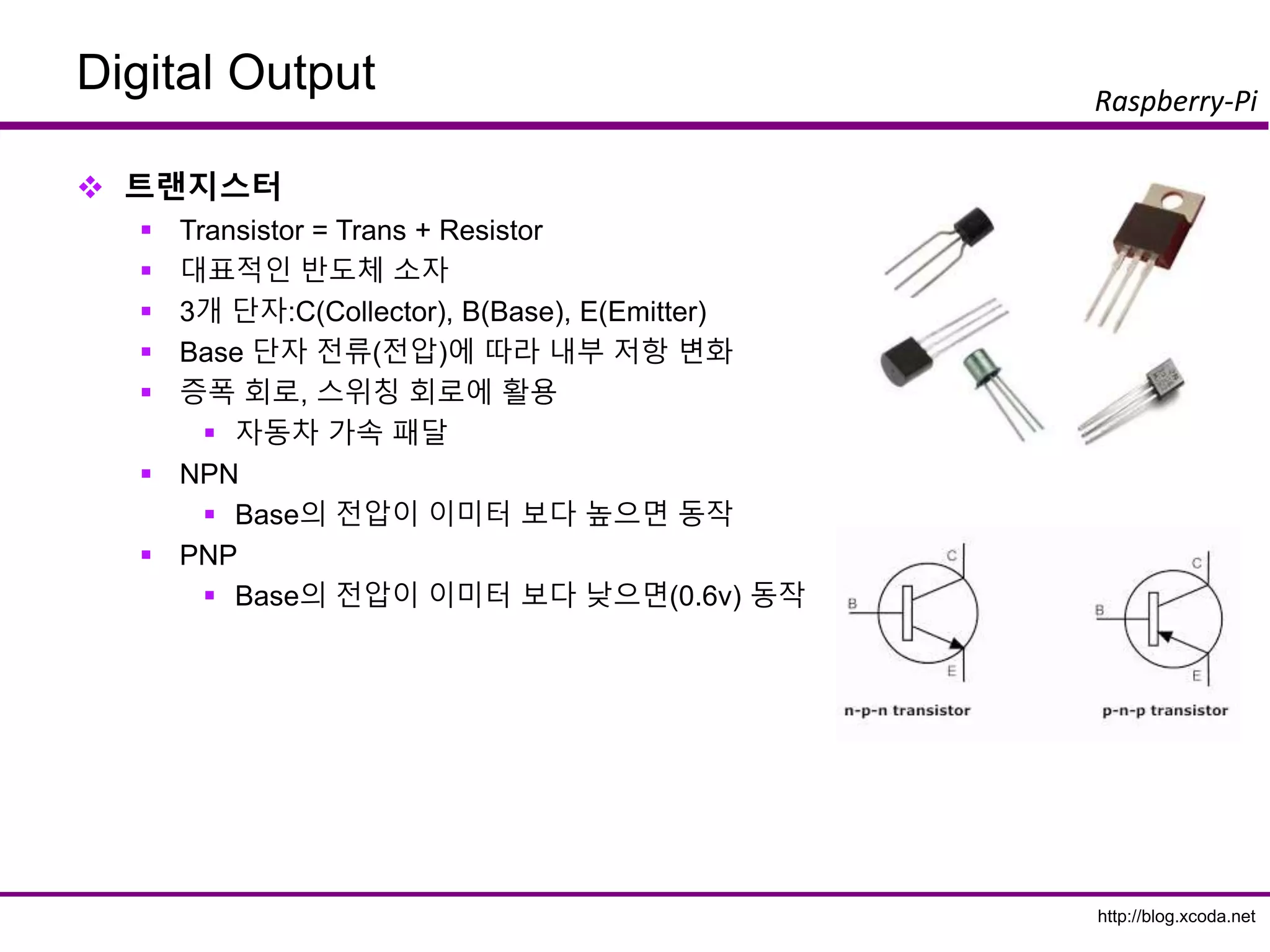
트랜지스터
Transistor = Trans + Resistor
대표적인 반도체 소자
3개 단자:C(Collector), B(Base), E(Emitter)
Base 단자 전류(전압)에 따라 내부 저항 변화
증폭 회로, 스위칭 회로에 활용
자동차 가속 패달
NPN
Base의 전압이 이미터 보다 높으면 동작
PNP
Base의 전압이 이미터 보다 낮으면(0.6v) 동작
49.
http://blog.xcoda.net
Raspberry-Pi
Digital Output
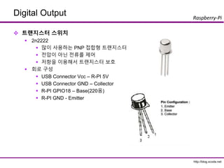
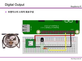
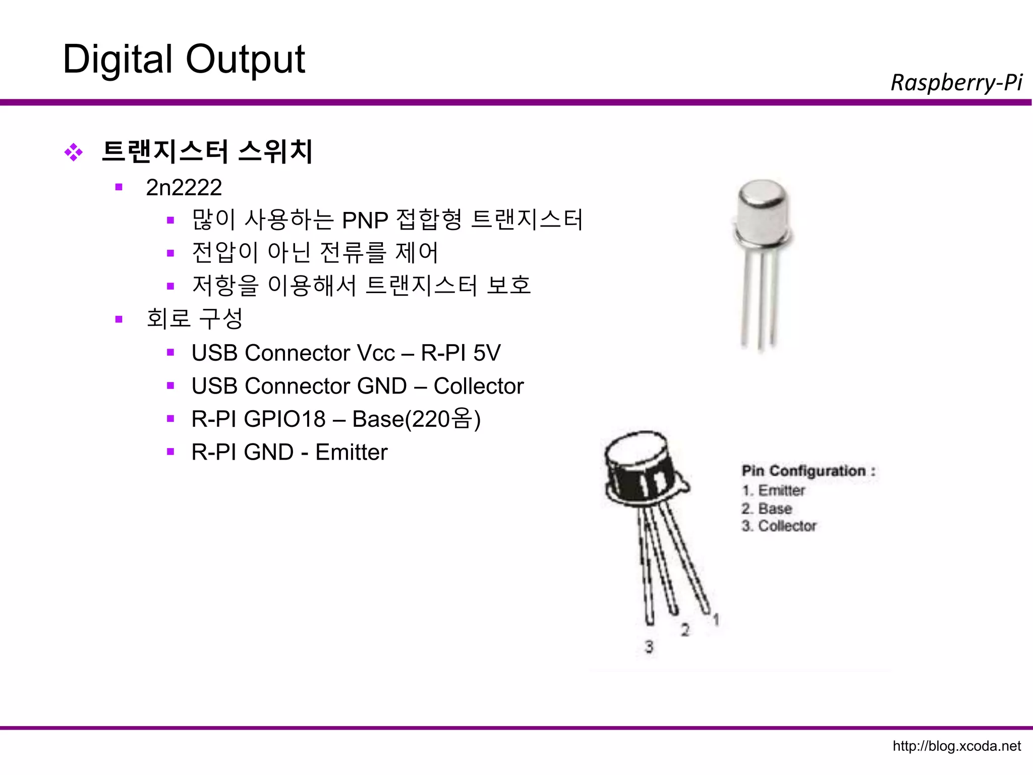
트랜지스터스위치
2n2222
많이 사용하는 PNP 접합형 트랜지스터
전압이 아닌 전류를 제어
저항을 이용해서 트랜지스터 보호
회로 구성
USB Connector Vcc – R-PI 5V
USB Connector GND – Collector
R-PI GPIO18 – Base(220옴)
R-PI GND - Emitter
http://blog.xcoda.net
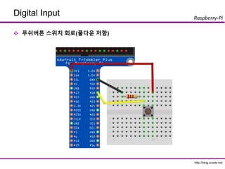
Raspberry-Pi
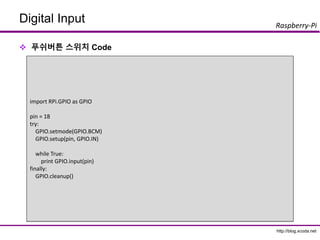
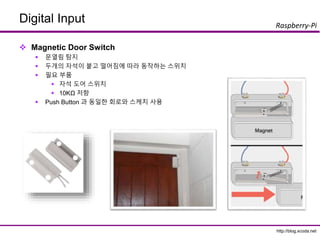
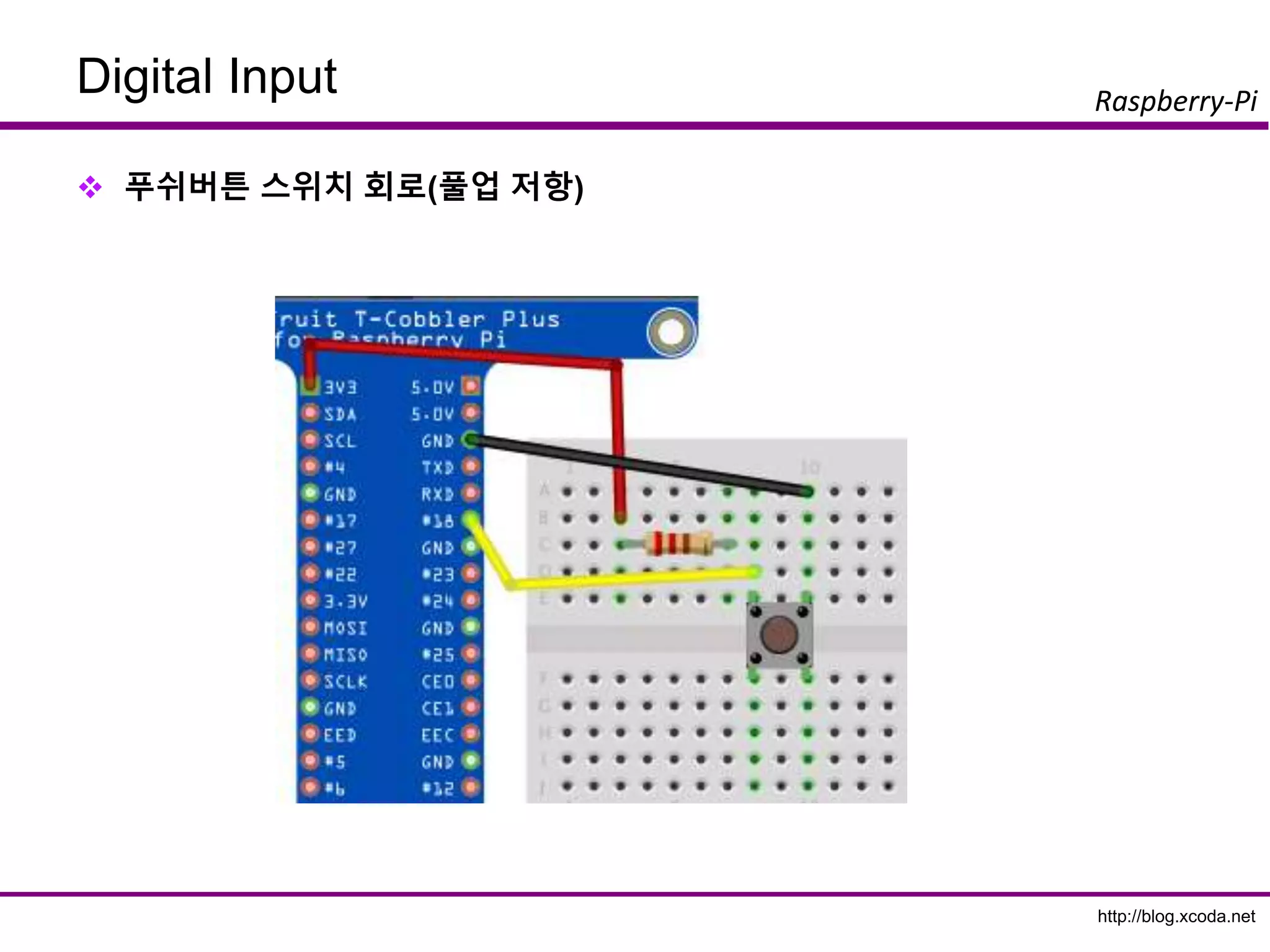
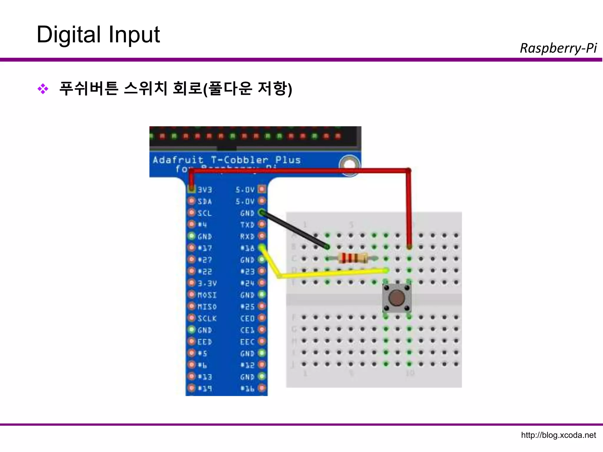
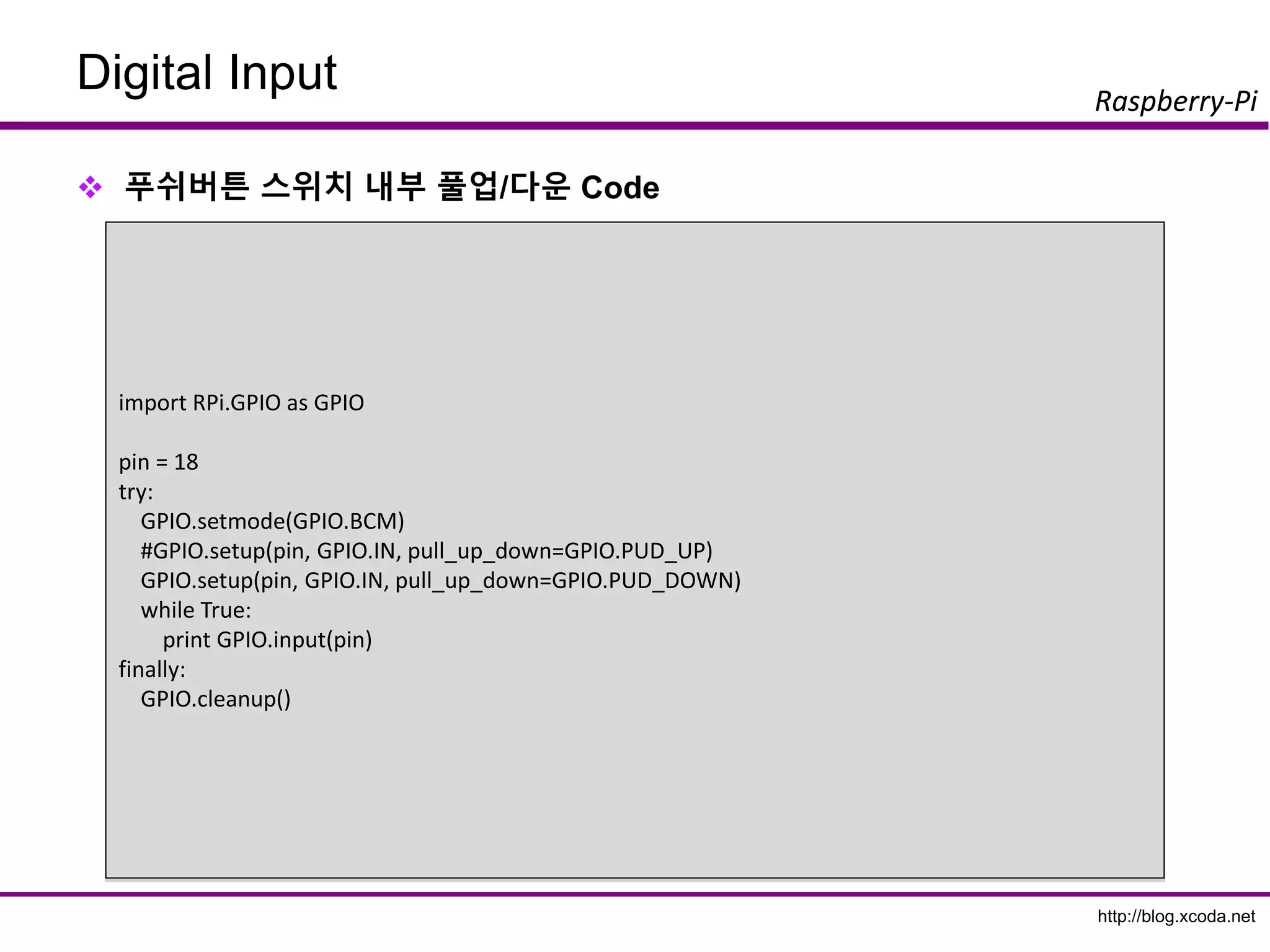
Digital Input
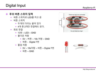
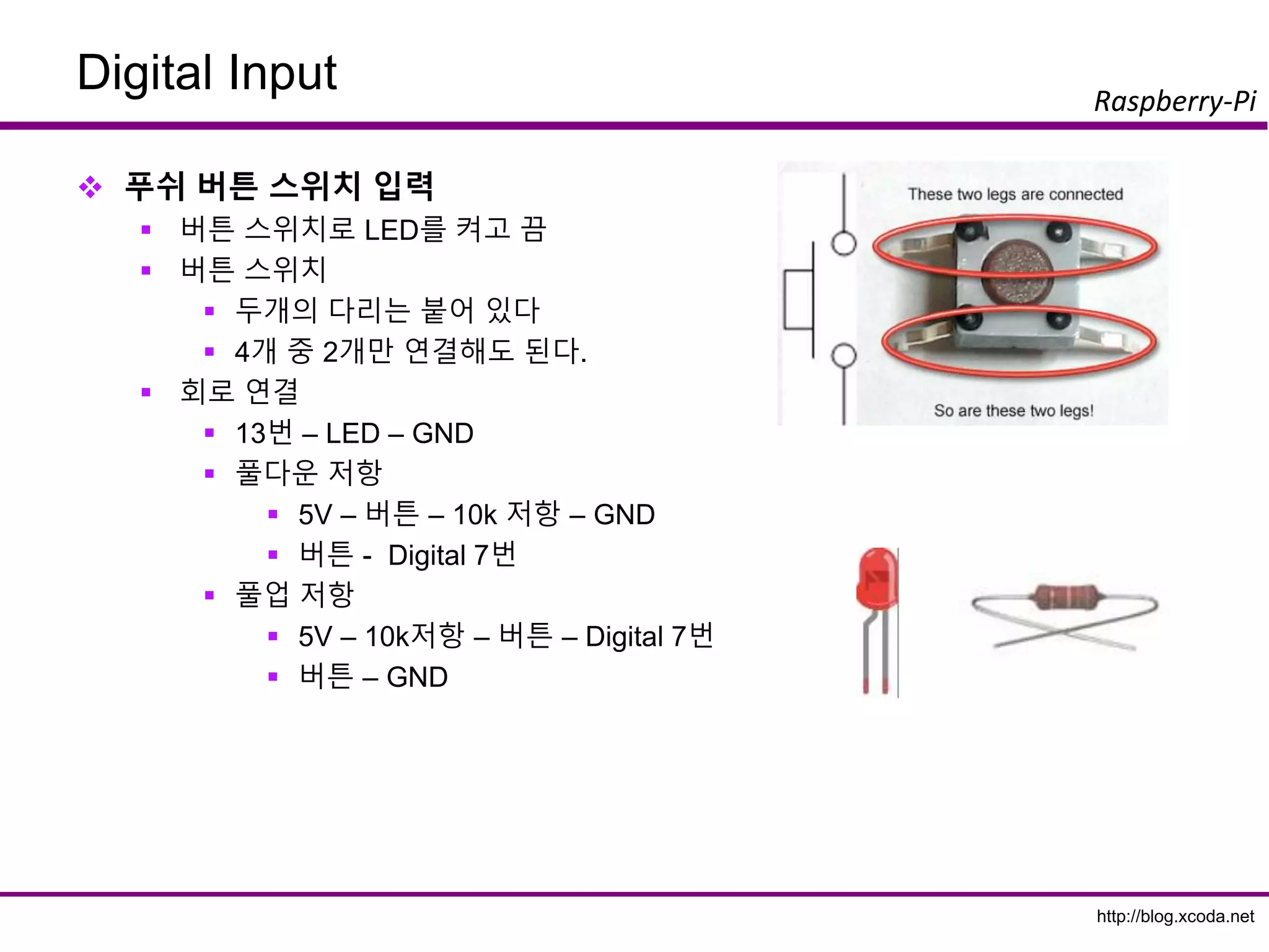
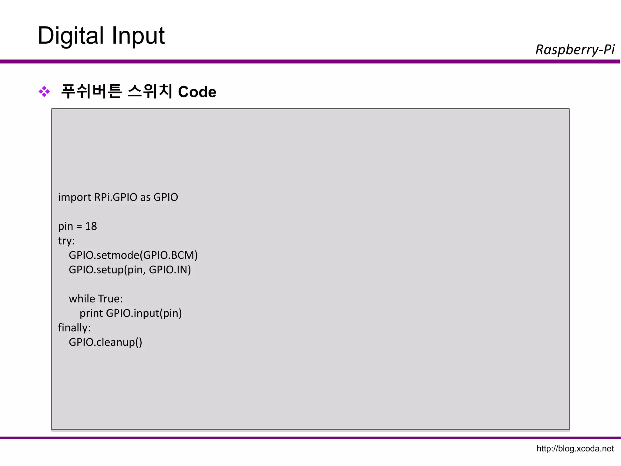
푸쉬버튼 스위치 입력
버튼 스위치로 LED를 켜고 끔
버튼 스위치
두개의 다리는 붙어 있다
4개 중 2개만 연결해도 된다.
회로 연결
13번 – LED – GND
풀다운 저항
5V – 버튼 – 10k 저항 – GND
버튼 - Digital 7번
풀업 저항
5V – 10k저항 – 버튼 – Digital 7번
버튼 – GND
54.
http://blog.xcoda.net
Raspberry-Pi
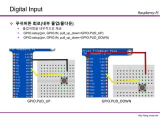
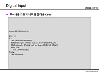
1. Digital Input
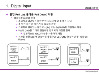
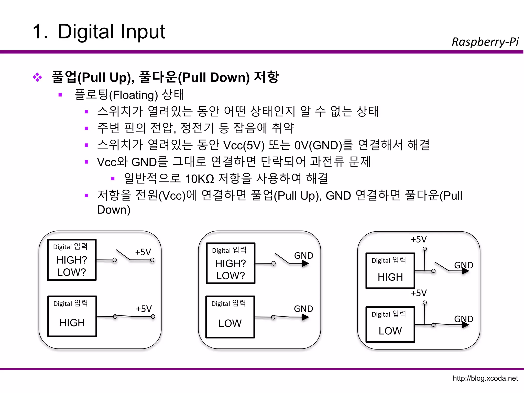
풀업(Pull Up), 풀다운(Pull Down) 저항
플로팅(Floating) 상태
스위치가 열려있는 동안 어떤 상태인지 알 수 없는 상태
주변 핀의 전압, 정전기 등 잡음에 취약
스위치가 열려있는 동안 Vcc(5V) 또는 0V(GND)를 연결해서 해결
Vcc와 GND를 그대로 연결하면 단락되어 과전류 문제
일반적으로 10KΩ 저항을 사용하여 해결
저항을 전원(Vcc)에 연결하면 풀업(Pull Up), GND 연결하면 풀다운(Pull
Down)
HIGH?
LOW?
+5V
Digital 입력
HIGH
+5V
Digital 입력
HIGH?
LOW?
GND
Digital 입력
LOW
GND
Digital 입력
LOW
GND
Digital 입력
+5V
HIGH
GND
Digital 입력
+5V
http://blog.xcoda.net
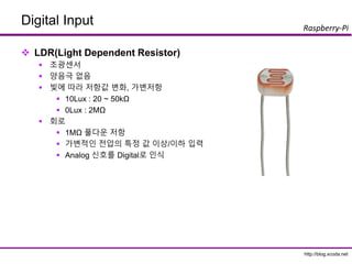
Raspberry-Pi
Digital Input
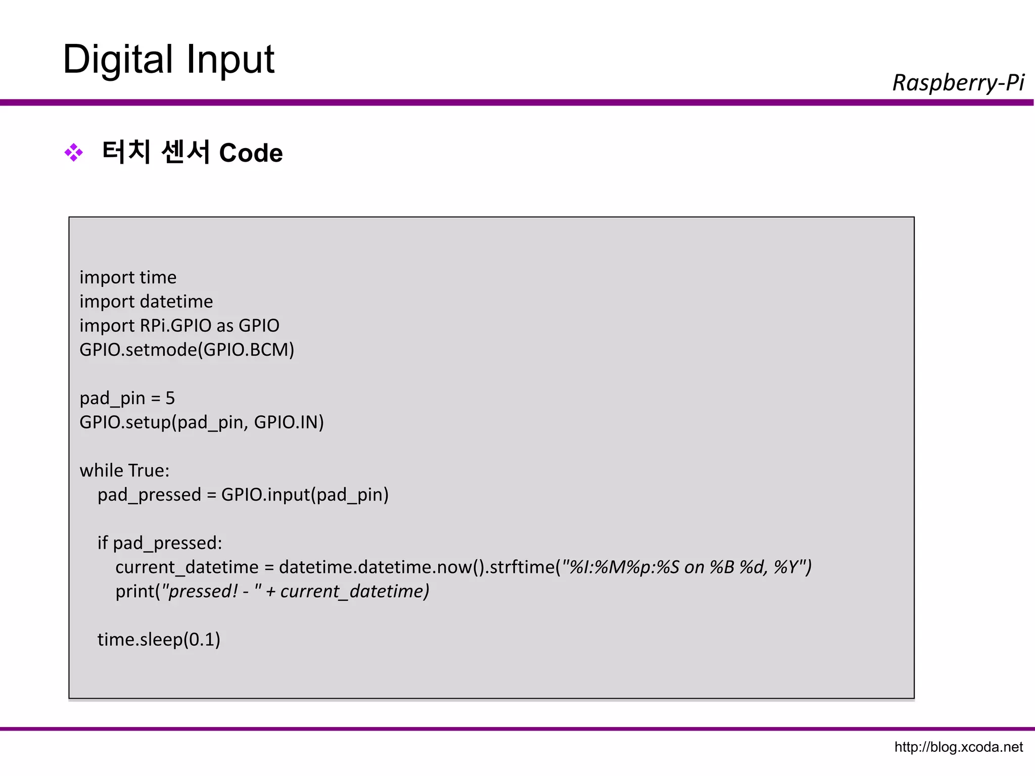
LDR(조도센서)Code
import RPi.GPIO as GPIO
import time
try:
pin = 18
GPIO.setmode(GPIO.BCM)
GPIO.setup(pin, GPIO.IN)
val = -1
while True:
read = GPIO.input(pin)
if read != val:
val = read
print time.strftime("%Y%m%d-%H%M%S"), val
#time.sleep(0.1)
finally:
print "clean up."
GPIO.cleanup()
64.
http://blog.xcoda.net
Raspberry-Pi
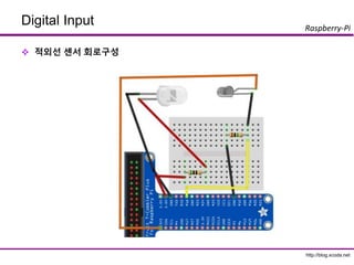
Digital Input
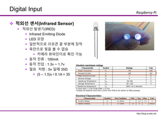
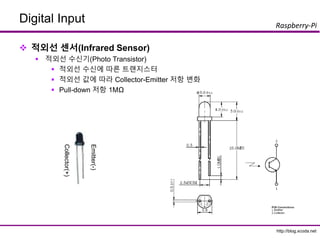
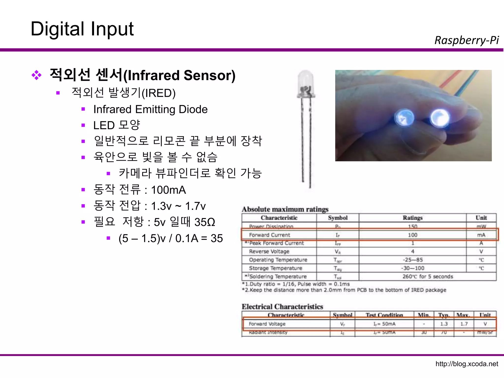
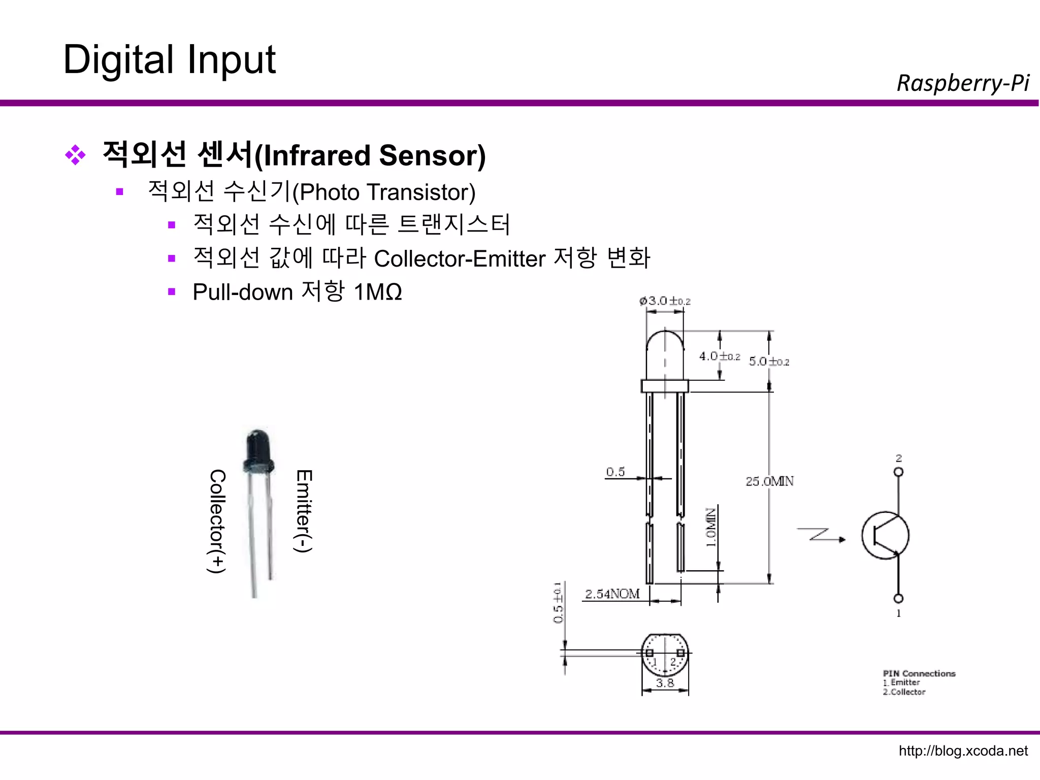
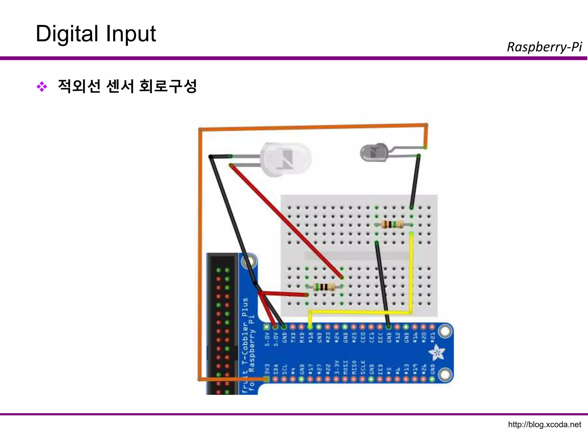
적외선센서(Infrared Sensor)
적외선 발생기(IRED)
Infrared Emitting Diode
LED 모양
일반적으로 리모콘 끝 부분에 장착
육안으로 빛을 볼 수 없슴
카메라 뷰파인더로 확인 가능
동작 전류 : 100mA
동작 전압 : 1.3v ~ 1.7v
필요 저항 : 5v 일때 35Ω
(5 – 1.5)v / 0.1A = 35
http://blog.xcoda.net
Raspberry-Pi
Digital Input
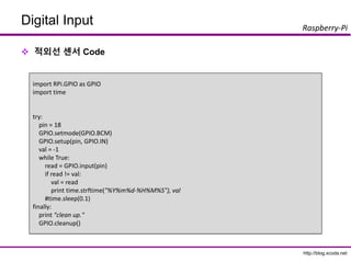
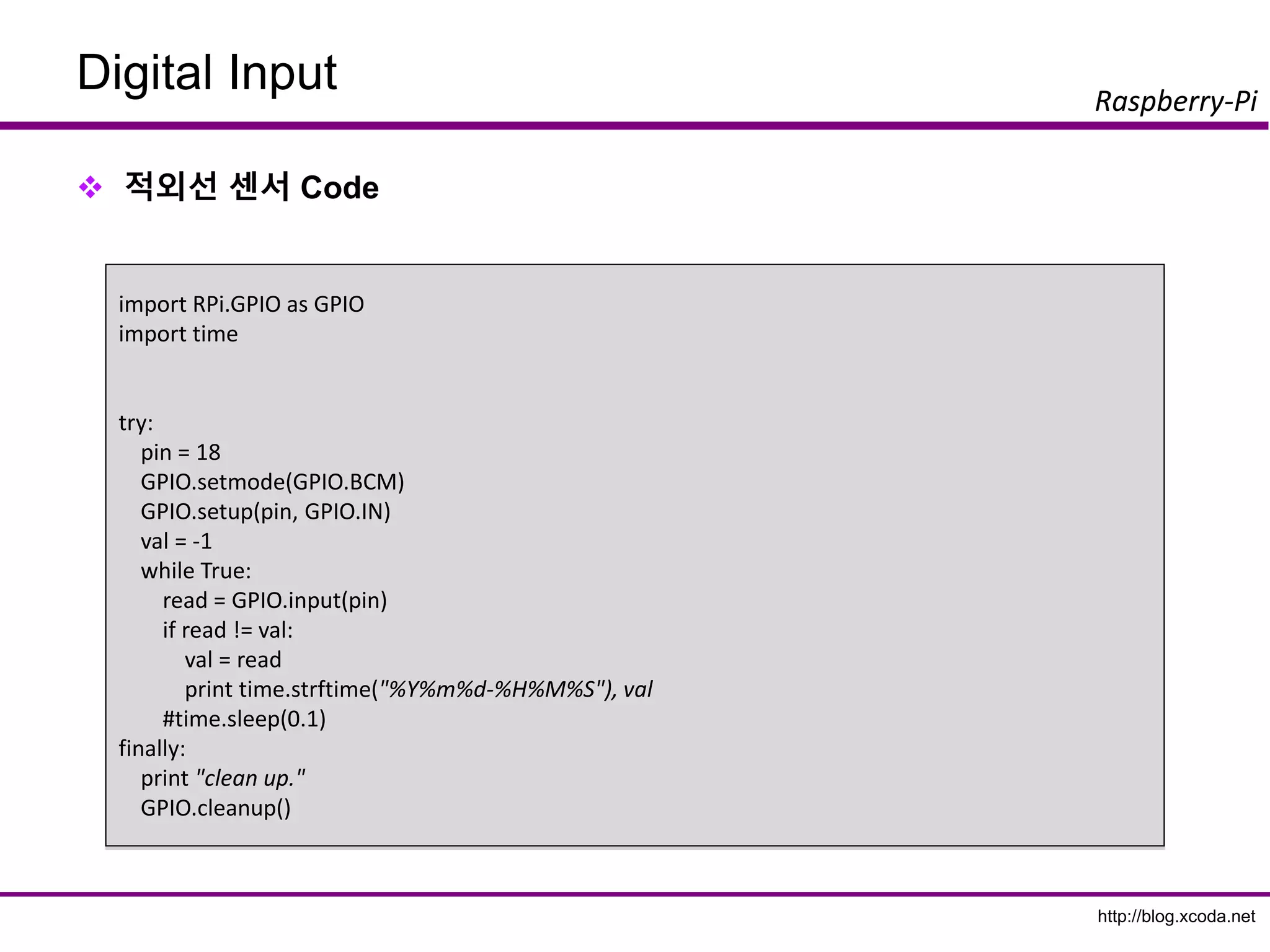
적외선센서 Code
import RPi.GPIO as GPIO
import time
try:
pin = 18
GPIO.setmode(GPIO.BCM)
GPIO.setup(pin, GPIO.IN)
val = -1
while True:
read = GPIO.input(pin)
if read != val:
val = read
print time.strftime("%Y%m%d-%H%M%S"), val
#time.sleep(0.1)
finally:
print "clean up."
GPIO.cleanup()
68.
http://blog.xcoda.net
Raspberry-Pi
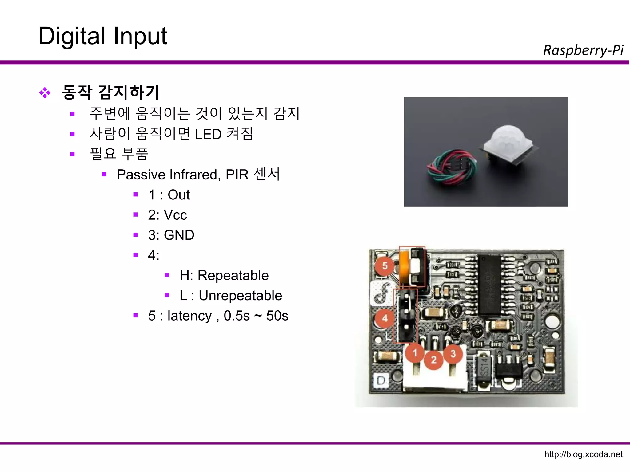
Digital Input
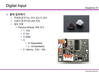
동작감지하기
주변에 움직이는 것이 있는지 감지
사람이 움직이면 LED 켜짐
필요 부품
Passive Infrared, PIR 센서
1 : Out
2: Vcc
3: GND
4:
H: Repeatable
L : Unrepeatable
5 : latency , 0.5s ~ 50s
69.
http://blog.xcoda.net
Raspberry-Pi
Digital Input
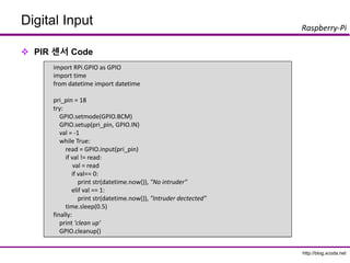
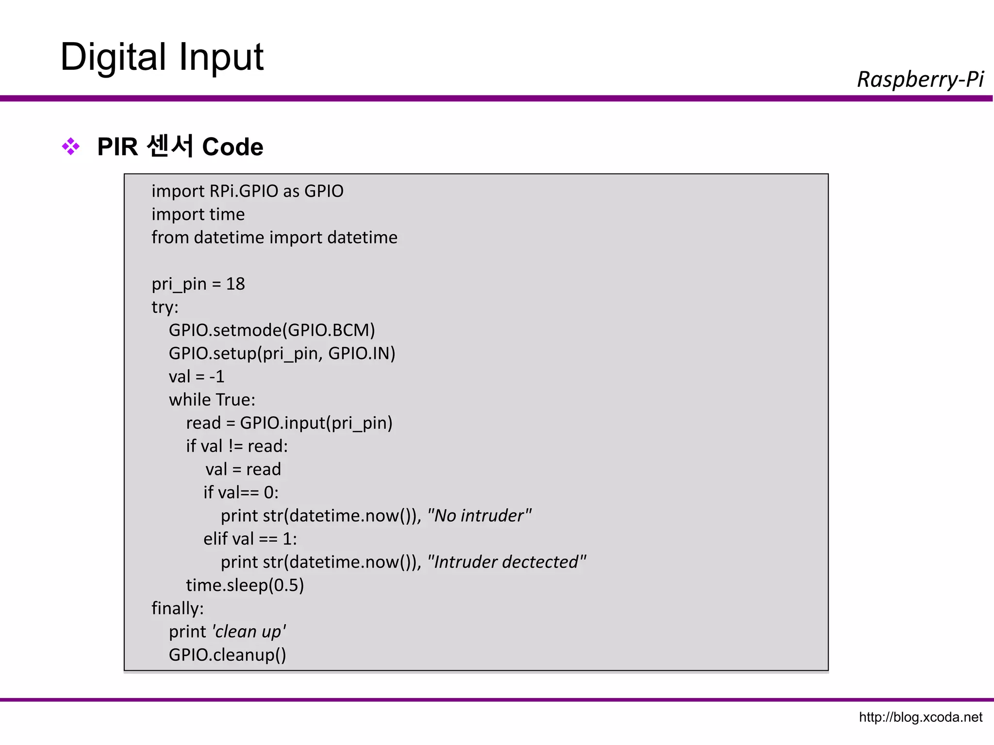
PIR센서 Code
import RPi.GPIO as GPIO
import time
from datetime import datetime
pri_pin = 18
try:
GPIO.setmode(GPIO.BCM)
GPIO.setup(pri_pin, GPIO.IN)
val = -1
while True:
read = GPIO.input(pri_pin)
if val != read:
val = read
if val== 0:
print str(datetime.now()), "No intruder"
elif val == 1:
print str(datetime.now()), "Intruder dectected"
time.sleep(0.5)
finally:
print 'clean up'
GPIO.cleanup()
http://blog.xcoda.net
Raspberry-Pi
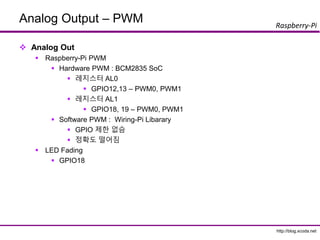
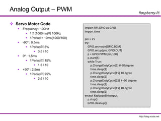
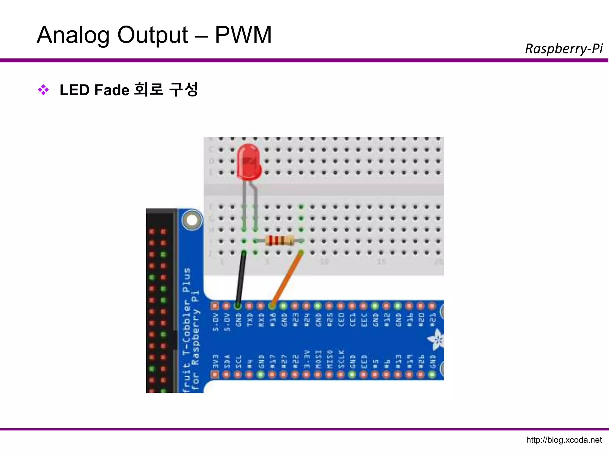
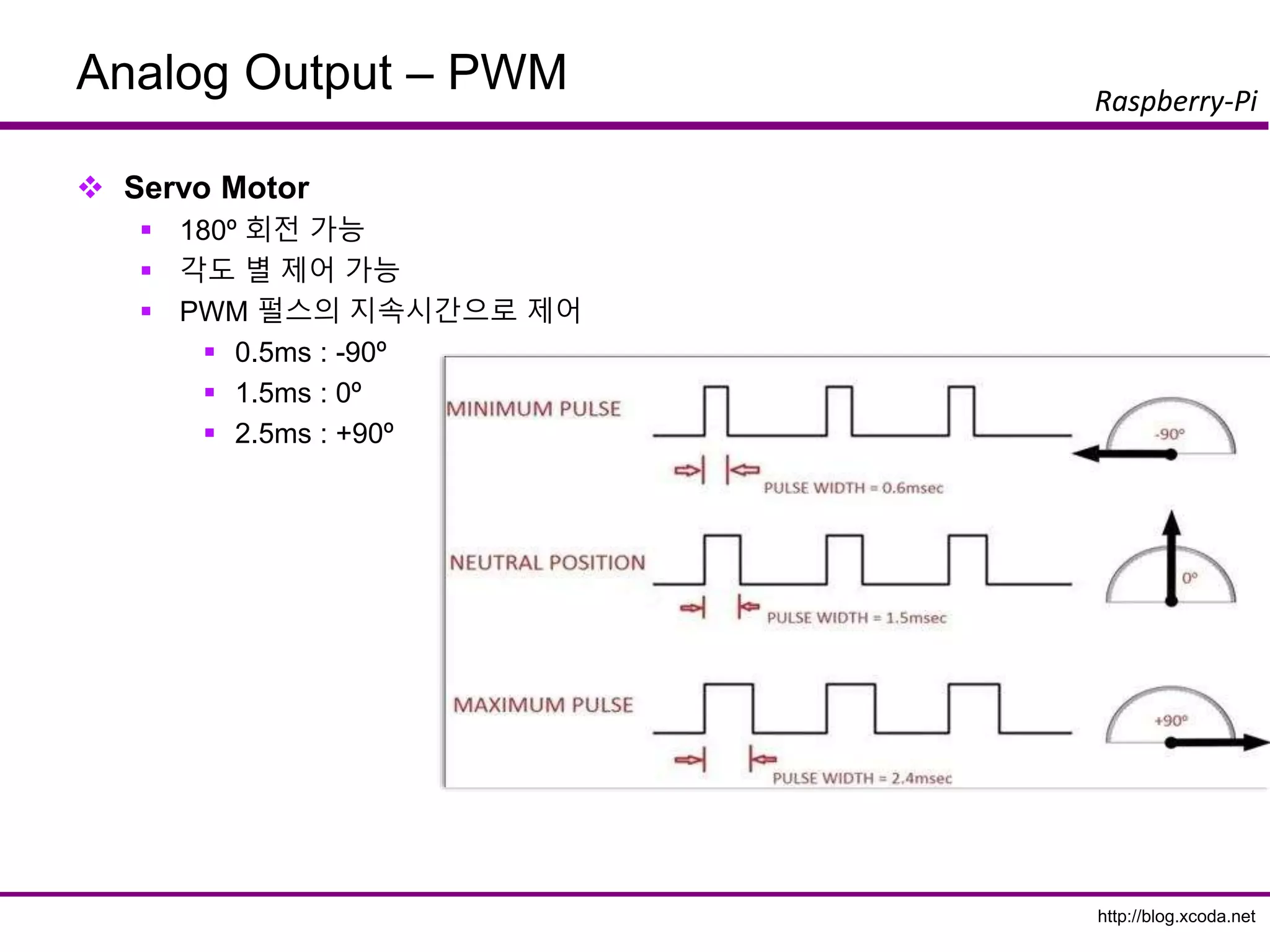
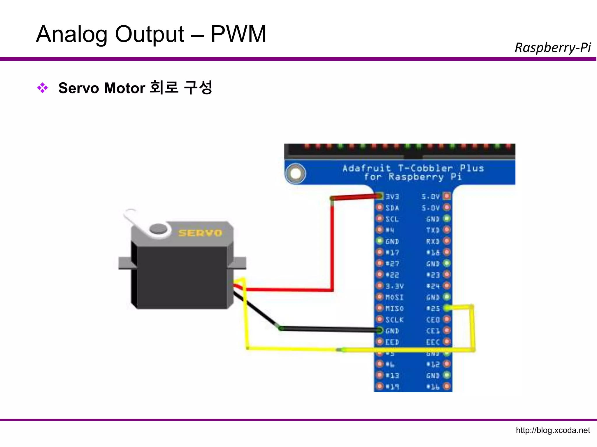
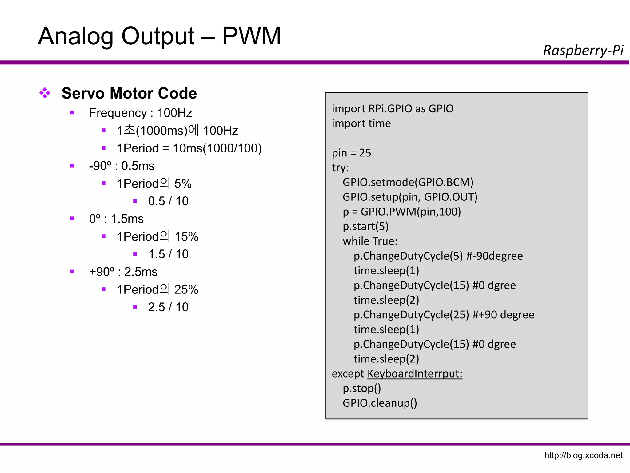
Analog Output –PWM
Analog Out
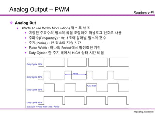
PWM( Pulse Width Modulation) 펄스 폭 변조
지정된 주파수의 펄스의 폭을 조절하여 아날로그 신호로 사용
주파수(Frequency) : Hz, 1초에 일어날 펄스의 갯수
주기(Period) : 한 펄스의 지속 시간
Pulse Width : 하나의 Period에서 활성화된 기간
Duty Cycle : 한 주기 내에서 HIGH 상태 시간 비율
http://blog.xcoda.net
Raspberry-Pi
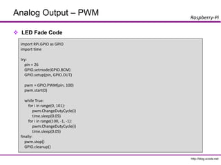
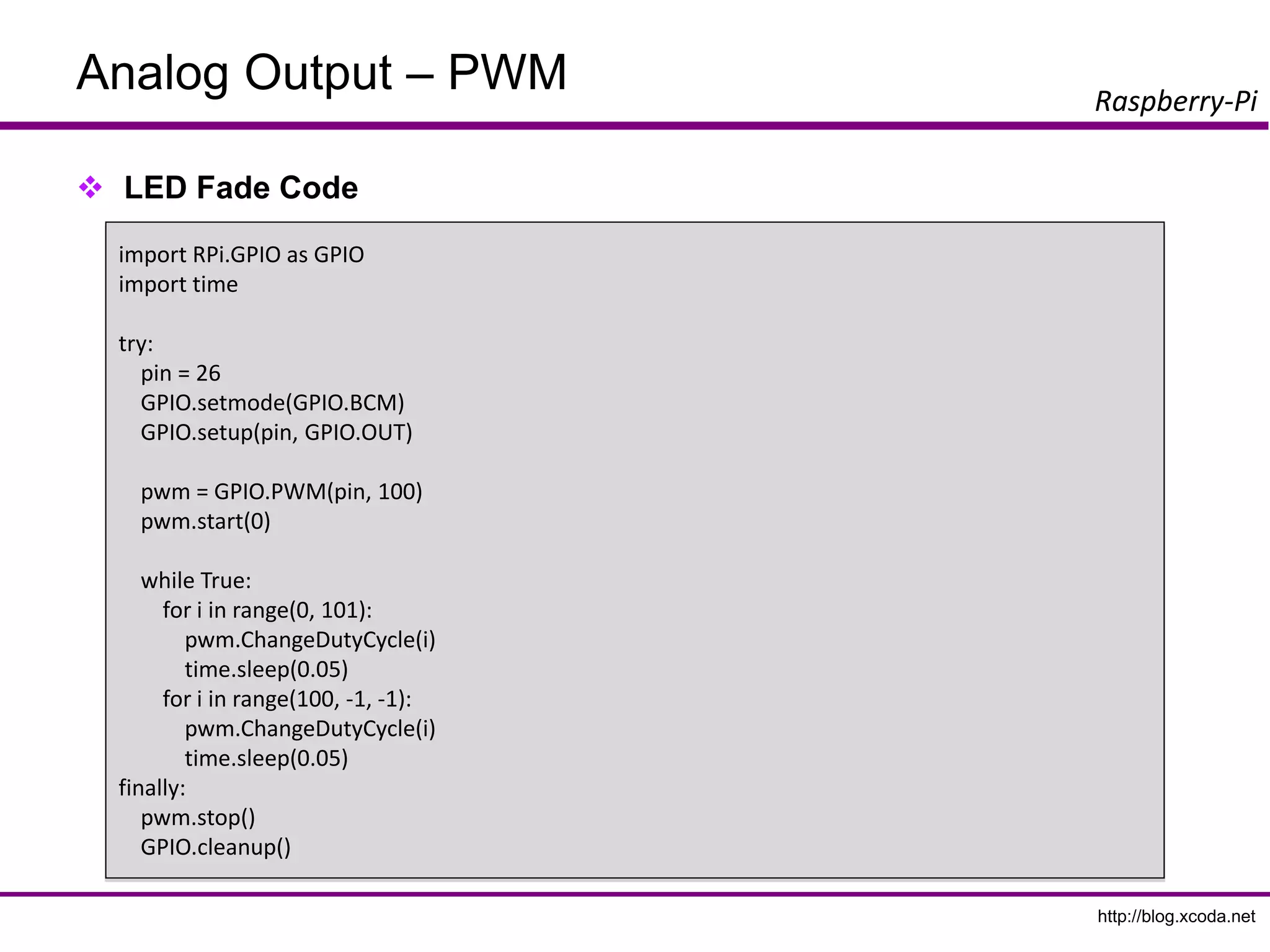
Analog Output –PWM
LED Fade Code
import RPi.GPIO as GPIO
import time
try:
pin = 26
GPIO.setmode(GPIO.BCM)
GPIO.setup(pin, GPIO.OUT)
pwm = GPIO.PWM(pin, 100)
pwm.start(0)
while True:
for i in range(0, 101):
pwm.ChangeDutyCycle(i)
time.sleep(0.05)
for i in range(100, -1, -1):
pwm.ChangeDutyCycle(i)
time.sleep(0.05)
finally:
pwm.stop()
GPIO.cleanup()
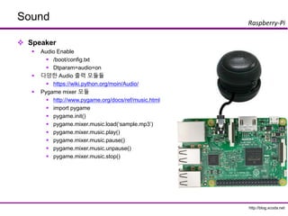
http://blog.xcoda.net
Raspberry-Pi
Sensor Modules
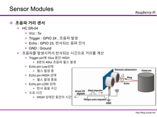
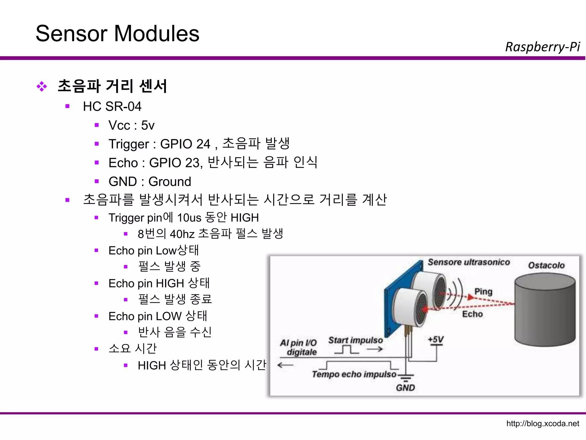
초음파거리 센서
HC SR-04
Vcc : 5v
Trigger : GPIO 24 , 초음파 발생
Echo : GPIO 23, 반사되는 음파 인식
GND : Ground
초음파를 발생시켜서 반사되는 시간으로 거리를 계산
Trigger pin에 10us 동안 HIGH
8번의 40hz 초음파 펄스 발생
Echo pin Low상태
펄스 발생 중
Echo pin HIGH 상태
펄스 발생 종료
Echo pin LOW 상태
반사 음을 수신
소요 시간
HIGH 상태인 동안의 시간
82.
http://blog.xcoda.net
Raspberry-Pi
Sensor Modules
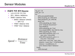
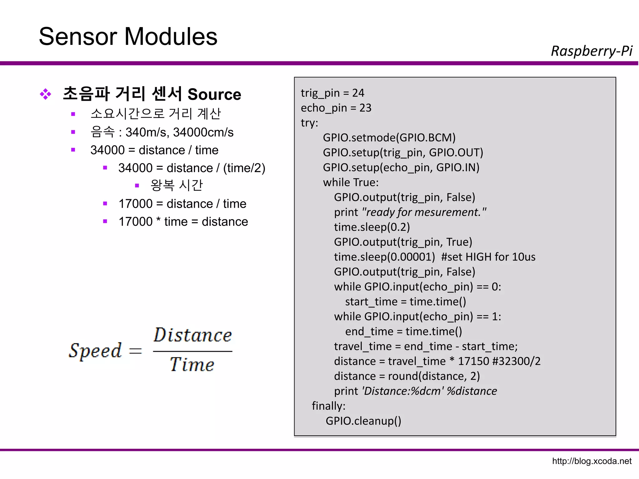
초음파거리 센서 Source
소요시간으로 거리 계산
음속 : 340m/s, 34000cm/s
34000 = distance / time
34000 = distance / (time/2)
왕복 시간
17000 = distance / time
17000 * time = distance
trig_pin = 24
echo_pin = 23
try:
GPIO.setmode(GPIO.BCM)
GPIO.setup(trig_pin, GPIO.OUT)
GPIO.setup(echo_pin, GPIO.IN)
while True:
GPIO.output(trig_pin, False)
print "ready for mesurement."
time.sleep(0.2)
GPIO.output(trig_pin, True)
time.sleep(0.00001) #set HIGH for 10us
GPIO.output(trig_pin, False)
while GPIO.input(echo_pin) == 0:
start_time = time.time()
while GPIO.input(echo_pin) == 1:
end_time = time.time()
travel_time = end_time - start_time;
distance = travel_time * 17150 #32300/2
distance = round(distance, 2)
print 'Distance:%dcm' %distance
finally:
GPIO.cleanup()
83.
http://blog.xcoda.net
Raspberry-Pi
Sensor Modules
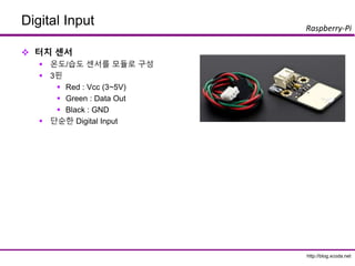
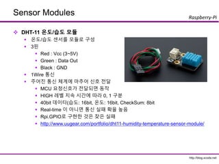
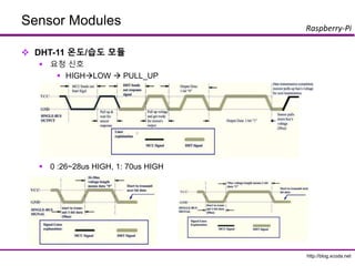
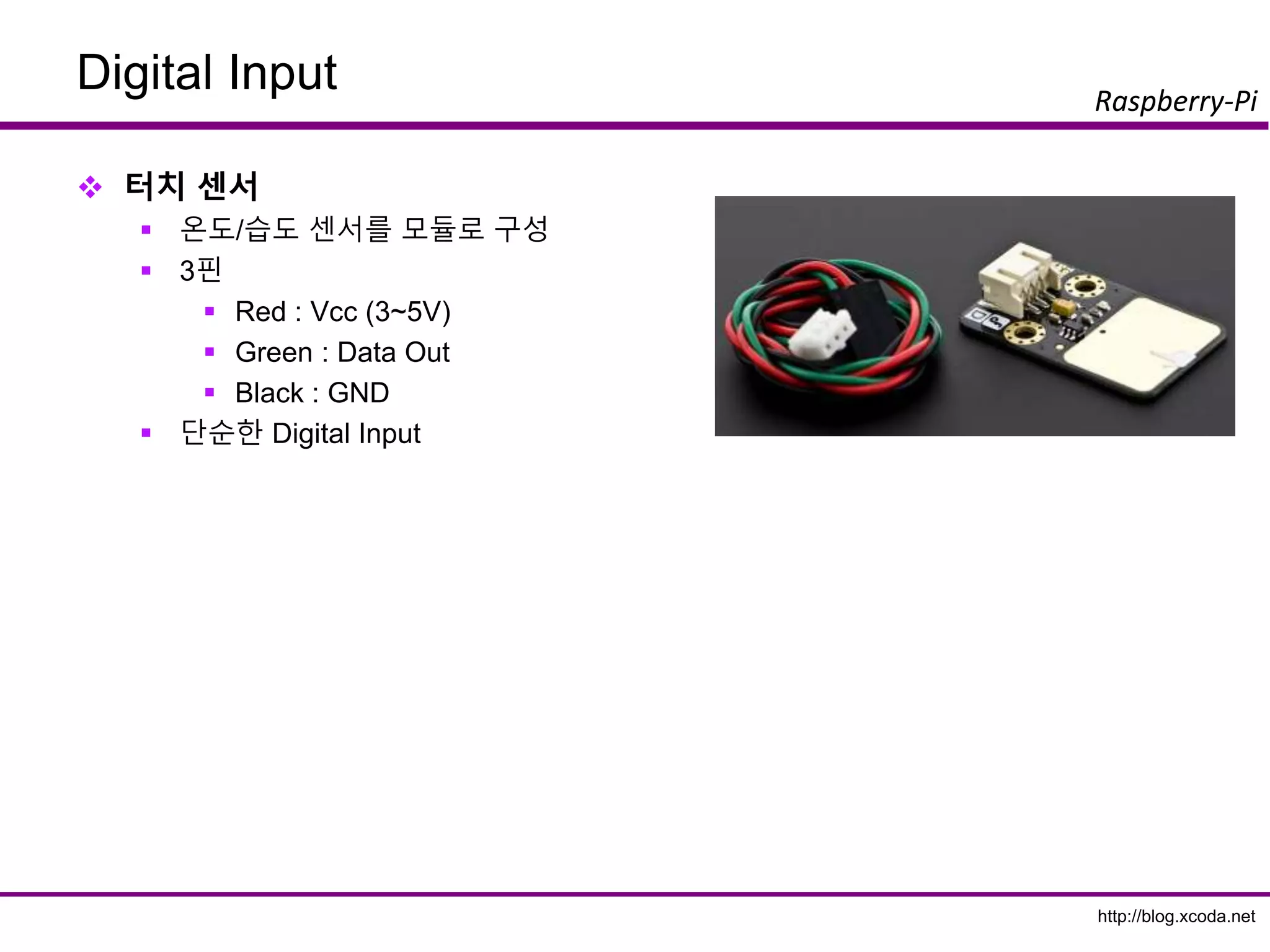
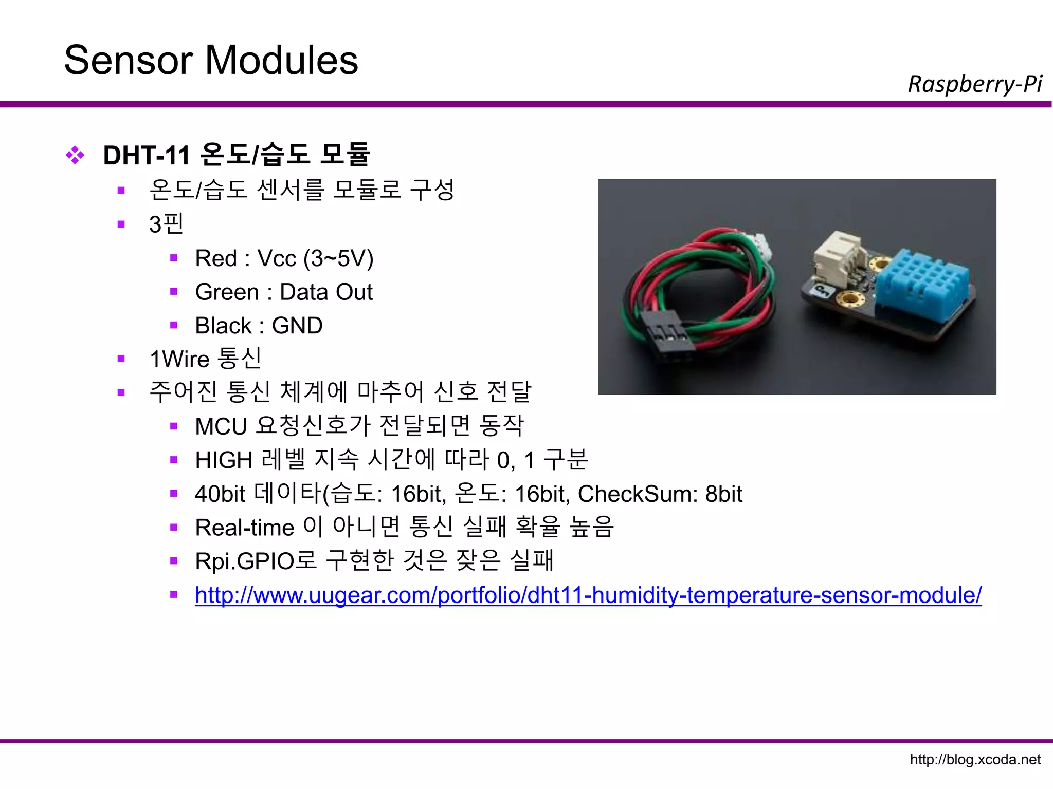
DHT-11온도/습도 모듈
온도/습도 센서를 모듈로 구성
3핀
Red : Vcc (3~5V)
Green : Data Out
Black : GND
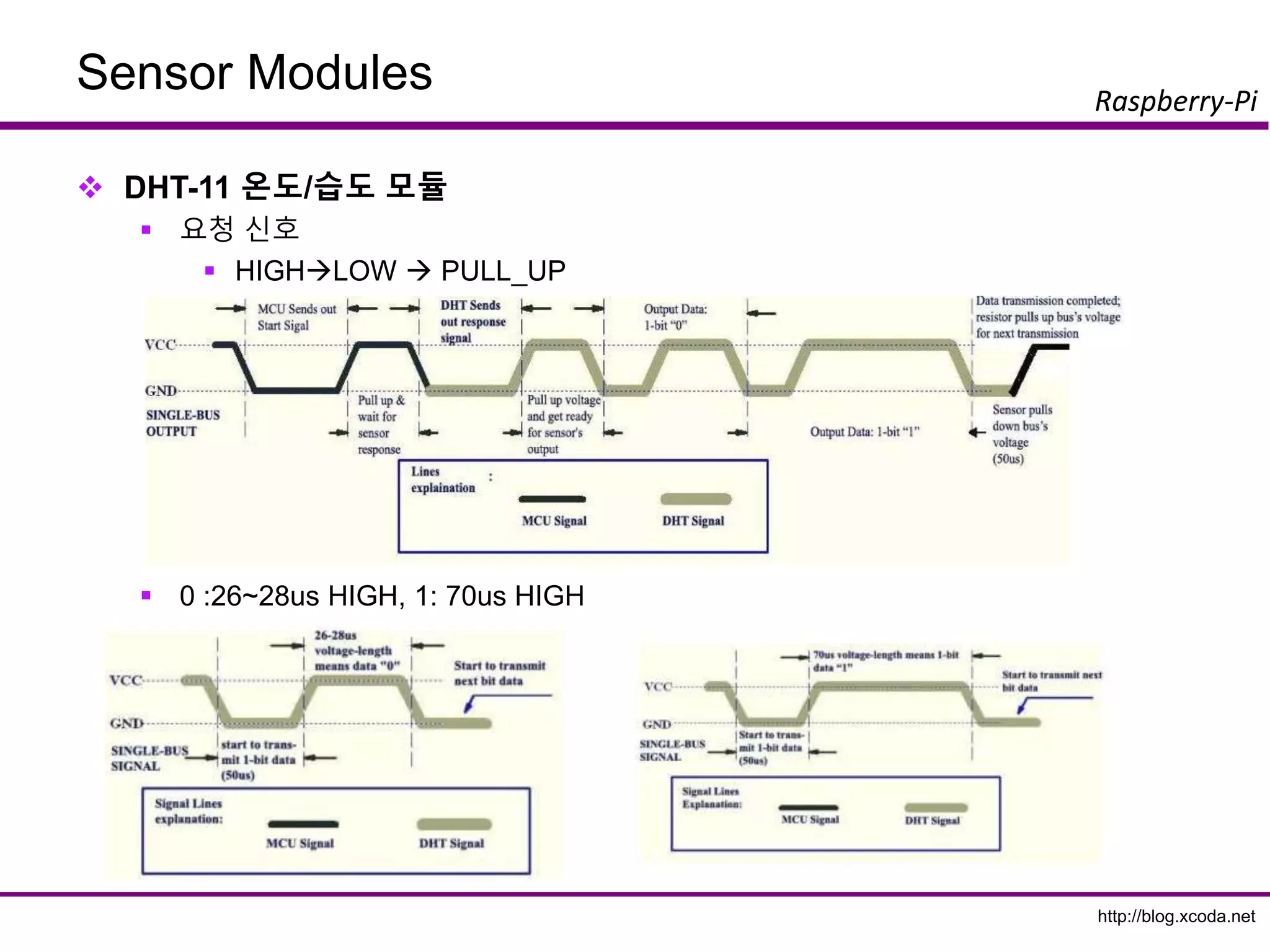
1Wire 통신
주어진 통신 체계에 마추어 신호 전달
MCU 요청신호가 전달되면 동작
HIGH 레벨 지속 시간에 따라 0, 1 구분
40bit 데이타(습도: 16bit, 온도: 16bit, CheckSum: 8bit
Real-time 이 아니면 통신 실패 확율 높음
Rpi.GPIO로 구현한 것은 잦은 실패
http://www.uugear.com/portfolio/dht11-humidity-temperature-sensor-module/
http://blog.xcoda.net
Raspberry-Pi
Sensor Modules
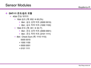
DHT-11온도/습도 모듈
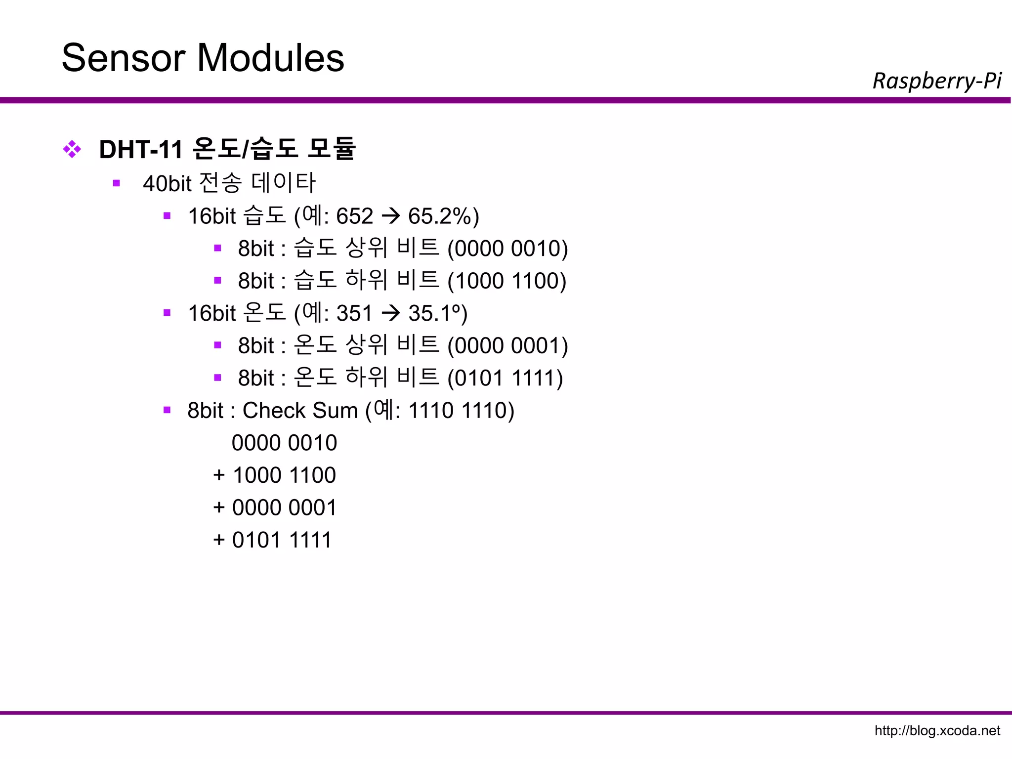
40bit 전송 데이타
16bit 습도 (예: 652 65.2%)
8bit : 습도 상위 비트 (0000 0010)
8bit : 습도 하위 비트 (1000 1100)
16bit 온도 (예: 351 35.1º)
8bit : 온도 상위 비트 (0000 0001)
8bit : 온도 하위 비트 (0101 1111)
8bit : Check Sum (예: 1110 1110)
0000 0010
+ 1000 1100
+ 0000 0001
+ 0101 1111
86.
http://blog.xcoda.net
Raspberry-Pi
Sensor Modules
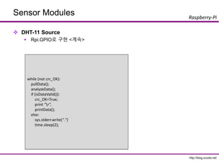
DHT-11Source
Rpi.GPIO로 구현
https://github.com/netikras/r-pi_DHT11/blob/master/dht11.py
def pullData():
global data
global effectiveData
global pin
data = []
effectiveData = []
GPIO.setup(pin,GPIO.OUT)
GPIO.output(pin,GPIO.HIGH)
time.sleep(0.025)
GPIO.output(pin,GPIO.LOW)
time.sleep(0.14)
GPIO.setup(pin, GPIO.IN, pull_up_down=GPIO.PUD_UP)
for i in range(0,1000):
data.append(GPIO.input(pin))
import RPi.GPIO as GPIO
import time
import sys
def bin2dec(string_num):
return str(int(string_num, 2))
data = []
effectiveData = []
bits_min=999;
bits_max=0;
HumidityBit = ""
TemperatureBit = ""
crc = ""
crc_OK = False;
Humidity = 0
Temperature = 0
pin=4
GPIO.setmode(GPIO.BCM)
87.
http://blog.xcoda.net
Raspberry-Pi
Sensor Modules
DHT-11Source
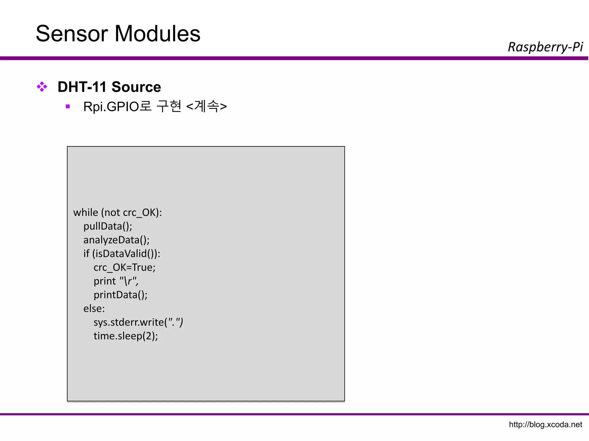
Rpi.GPIO로 구현 <계속>
for i in range(0, 40):
buffer = "";
while(seek < len(data) and data[seek] == 0):
seek+=1;
while(seek < len(data) and data[seek] == 1):
seek+=1;
buffer += "1";
if (len(buffer) < bits_min):
bits_min = len(buffer)
if (len(buffer) > bits_max):
bits_max = len(buffer)
effectiveData.append(buffer);
def analyzeData():
seek=0;
bits_min=9999;
bits_max=0;
global HumidityBit
global TemperatureBit
global crc
global Humidity
global Temperature
HumidityBit = ""
TemperatureBit = ""
crc = ""
while(seek < len(data) and data[seek] == 0):
seek+=1;
while(seek < len(data) and data[seek] == 1):
seek+=1;
88.
http://blog.xcoda.net
Raspberry-Pi
Sensor Modules
DHT-11Source
Rpi.GPIO로 구현 <계속>
def isDataValid():
global Humidity
global Temperature
global crc
print "isDataValid(): H=%d, T=%d, crc=%d"% (int(Humidity),
int(Temperature), int(bin2dec(crc)))
if int(Humidity) + int(Temperature) == int(bin2dec(crc)):
return True;
else:
return False;
def printData():
global Humidity
global Temperature
print "H: "+Humidity
print "T: "+Temperature
for i in range(0, len(effectiveData)):
if (len(effectiveData[i]) < ((bits_max + bits_min)/2)):
effectiveData[i] = "0";
else:
effectiveData[i] = "1";
for i in range(0, 8):
HumidityBit += str(effectiveData[i]);
for i in range(16, 24):
TemperatureBit += str(effectiveData[i]);
for i in range(32, 40):
crc += str(effectiveData[i]);
Humidity = bin2dec(HumidityBit)
Temperature = bin2dec(TemperatureBit)
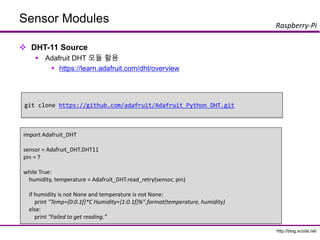
http://blog.xcoda.net
Raspberry-Pi
Sensor Modules
DHT-11Source
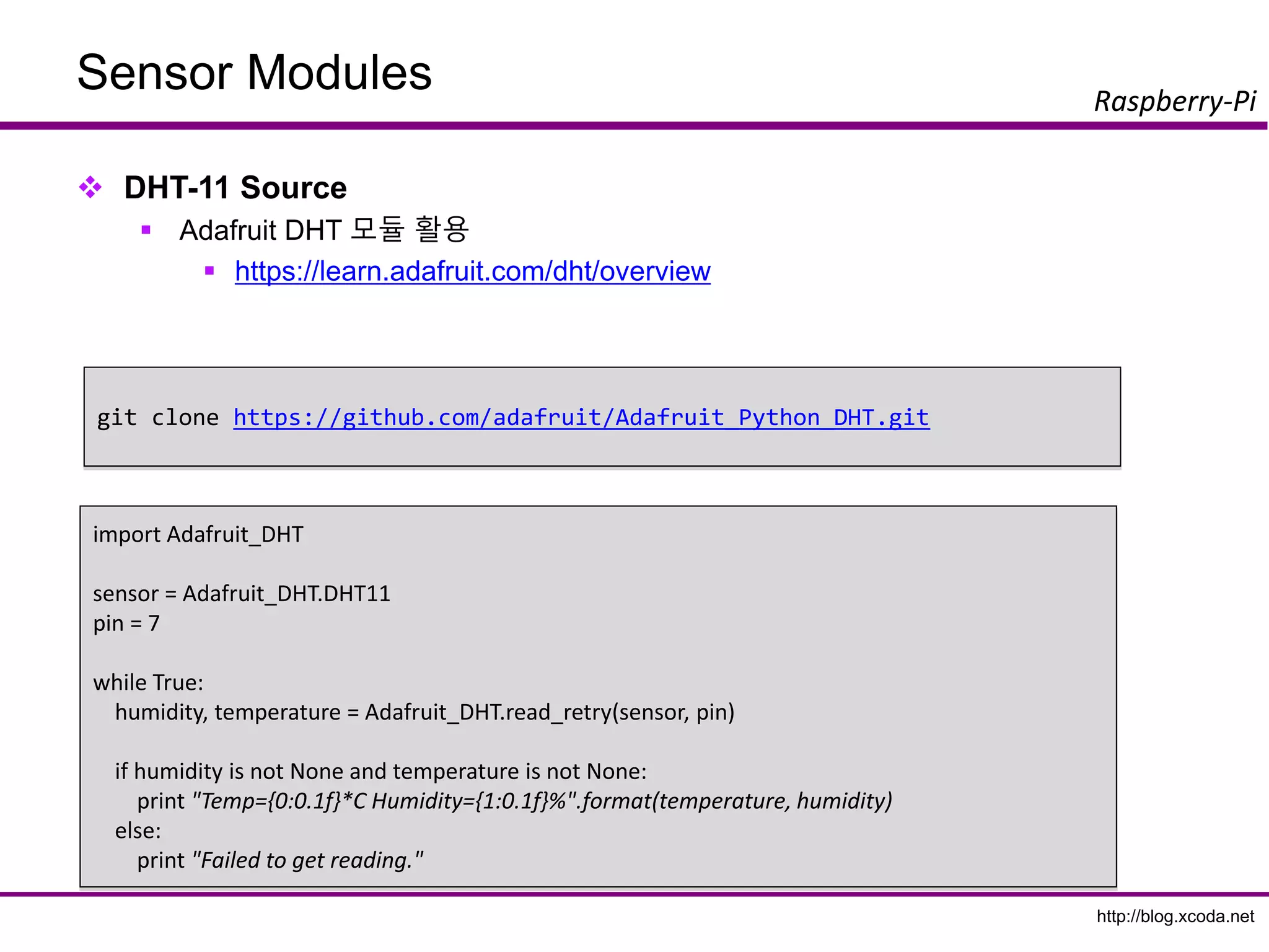
Adafruit DHT 모듈 활용
https://learn.adafruit.com/dht/overview
import Adafruit_DHT
sensor = Adafruit_DHT.DHT11
pin = 7
while True:
humidity, temperature = Adafruit_DHT.read_retry(sensor, pin)
if humidity is not None and temperature is not None:
print "Temp={0:0.1f}*C Humidity={1:0.1f}%".format(temperature, humidity)
else:
print "Failed to get reading."
git clone https://github.com/adafruit/Adafruit_Python_DHT.git
http://blog.xcoda.net
Raspberry-Pi
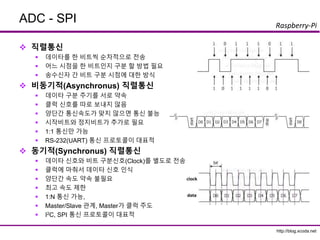
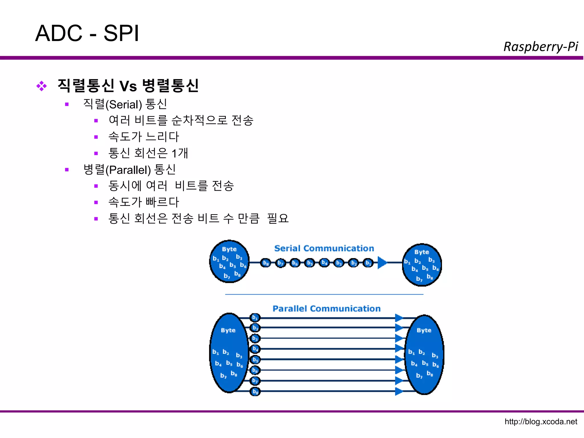
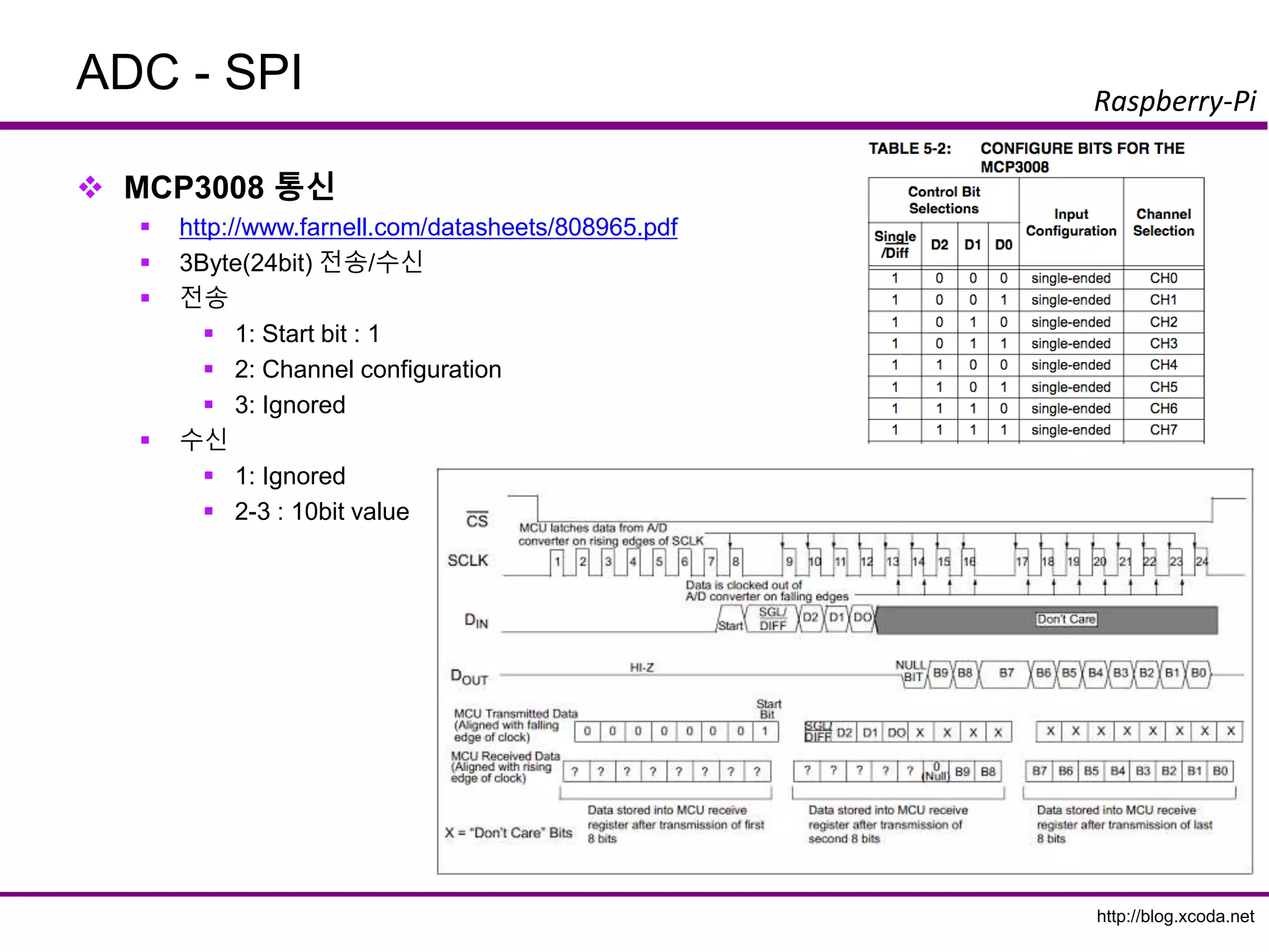
ADC - SPI
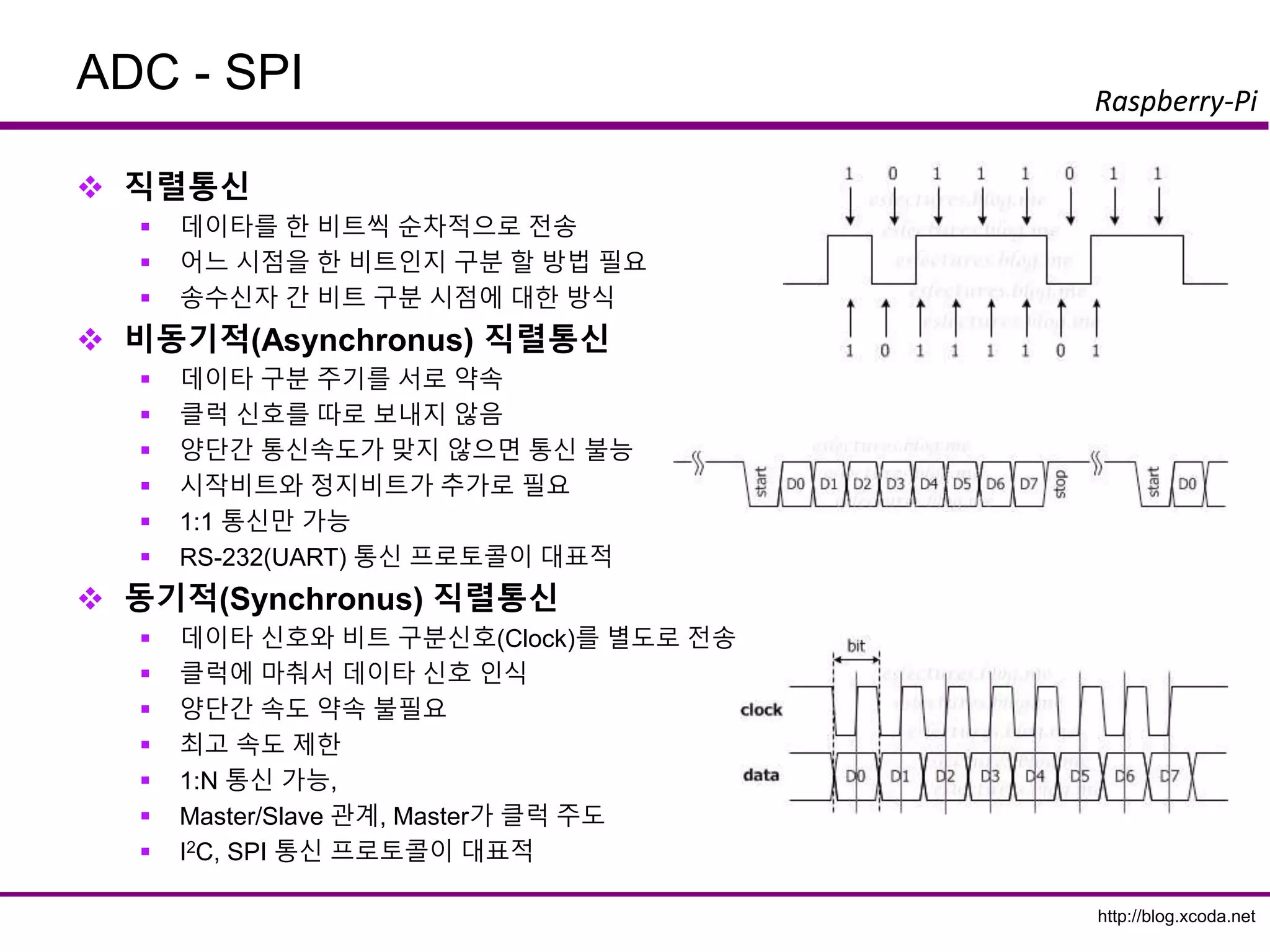
직렬통신
데이타를 한 비트씩 순차적으로 전송
어느 시점을 한 비트인지 구분 할 방법 필요
송수신자 간 비트 구분 시점에 대한 방식
비동기적(Asynchronus) 직렬통신
데이타 구분 주기를 서로 약속
클럭 신호를 따로 보내지 않음
양단간 통신속도가 맞지 않으면 통신 불능
시작비트와 정지비트가 추가로 필요
1:1 통신만 가능
RS-232(UART) 통신 프로토콜이 대표적
동기적(Synchronus) 직렬통신
데이타 신호와 비트 구분신호(Clock)를 별도로 전송
클럭에 마춰서 데이타 신호 인식
양단간 속도 약속 불필요
최고 속도 제한
1:N 통신 가능,
Master/Slave 관계, Master가 클럭 주도
I2C, SPI 통신 프로토콜이 대표적
95.
http://blog.xcoda.net
Raspberry-Pi
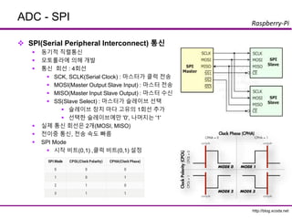
ADC - SPI
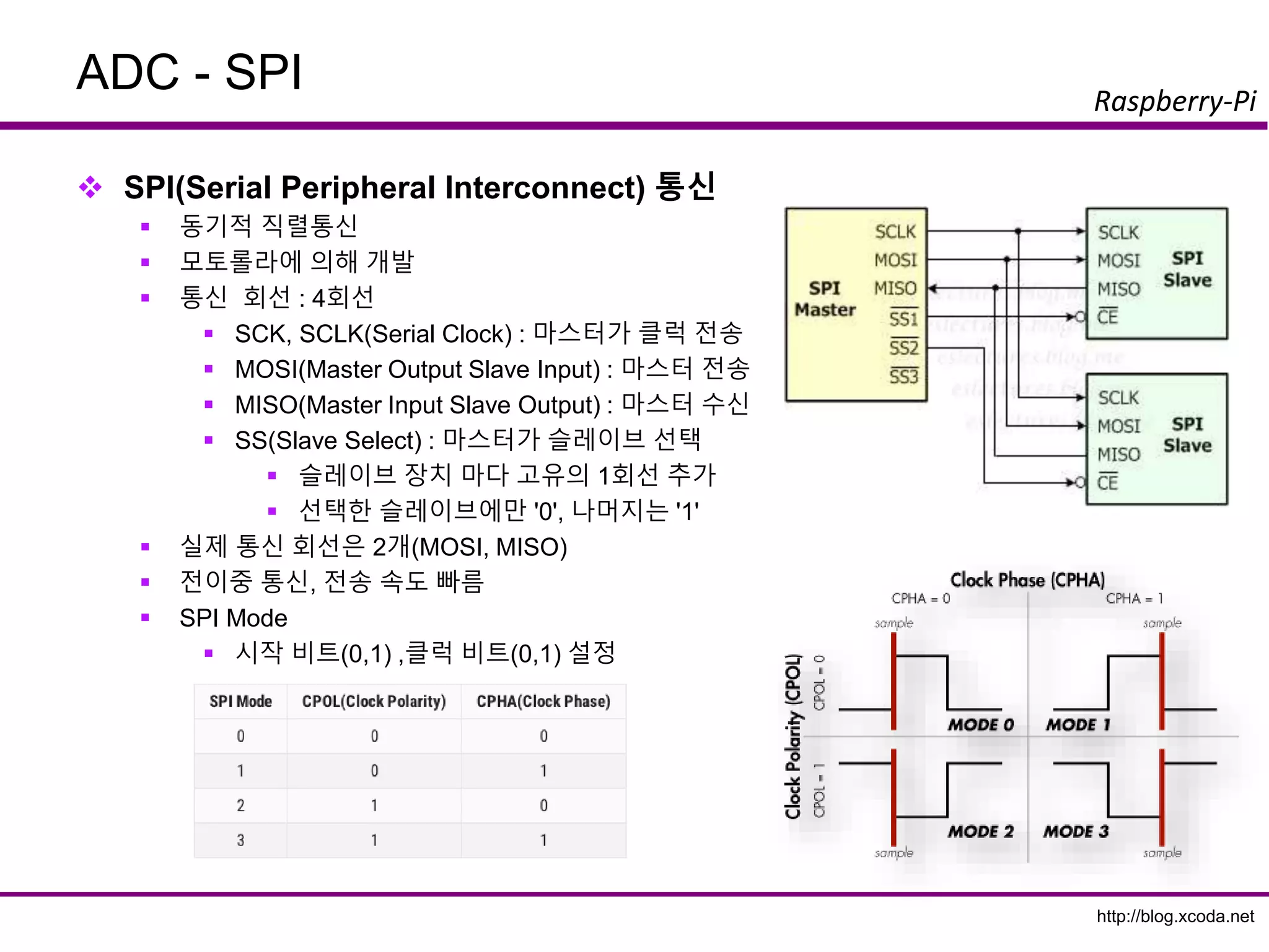
SPI(Serial Peripheral Interconnect) 통신
동기적 직렬통신
모토롤라에 의해 개발
통신 회선 : 4회선
SCK, SCLK(Serial Clock) : 마스터가 클럭 전송
MOSI(Master Output Slave Input) : 마스터 전송
MISO(Master Input Slave Output) : 마스터 수신
SS(Slave Select) : 마스터가 슬레이브 선택
슬레이브 장치 마다 고유의 1회선 추가
선택한 슬레이브에만 '0', 나머지는 '1'
실제 통신 회선은 2개(MOSI, MISO)
전이중 통신, 전송 속도 빠름
SPI Mode
시작 비트(0,1) ,클럭 비트(0,1) 설정
96.
http://blog.xcoda.net
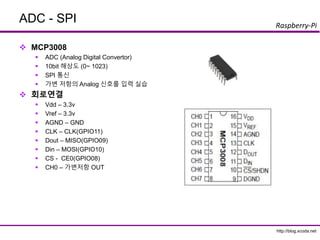
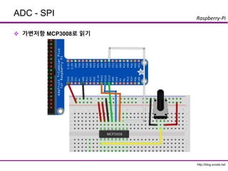
Raspberry-Pi
ADC - SPI
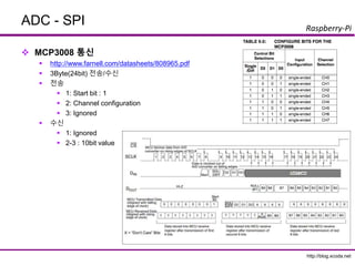
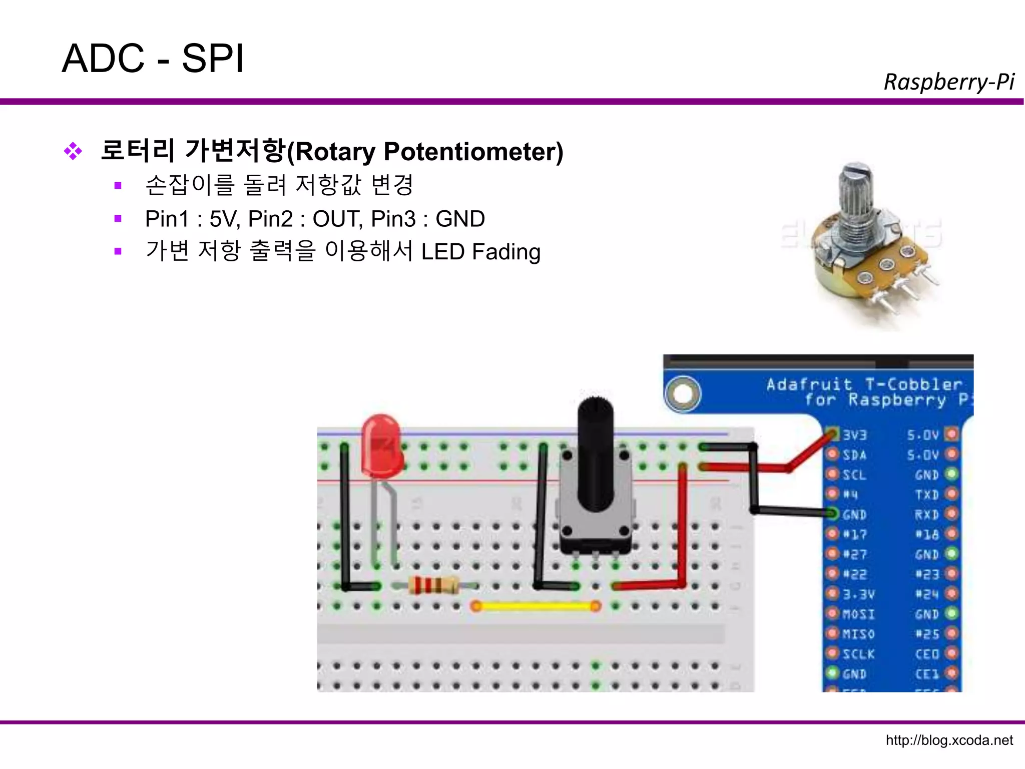
MCP3008
ADC (Analog Digital Convertor)
10bit 해상도 (0~ 1023)
SPI 통신
가변 저항의 Analog 신호를 입력 실습
회로연결
Vdd – 3.3v
Vref – 3.3v
AGND – GND
CLK – CLK(GPIO11)
Dout – MISO(GPIO09)
Din – MOSI(GPIO10)
CS - CE0(GPIO08)
CH0 – 가변저항 OUT
http://blog.xcoda.net
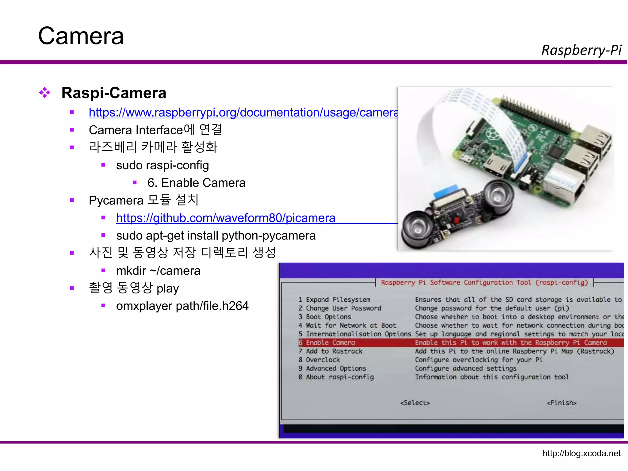
Raspberry-Pi
Camera
Pycamera Code
importtime
import picamera
with picamera.PiCamera() as camera:
try:
camera.start_preview()
while True:
shutter = input('insert key when you are ready to take photo. [photo:1, video:2] ')
now_str = time.strftime("%Y%m%d-%H%M%S")
if shutter == 1:
camera.capture('/home/pi/demo/camera/photo%s.gif' %now_str)
elif shutter == 2:
camera.start_recording('/home/pi/demo/camera/video%s.h264' %now_str)
raw_input('insert key when you want to stop recoding.')
camera.stop_recording()
finally:
camera.stop_preview()


![http://blog.xcoda.net
Raspberry-Pi
GPIO
Sysfs를 이용한 C Program – gpioled.c
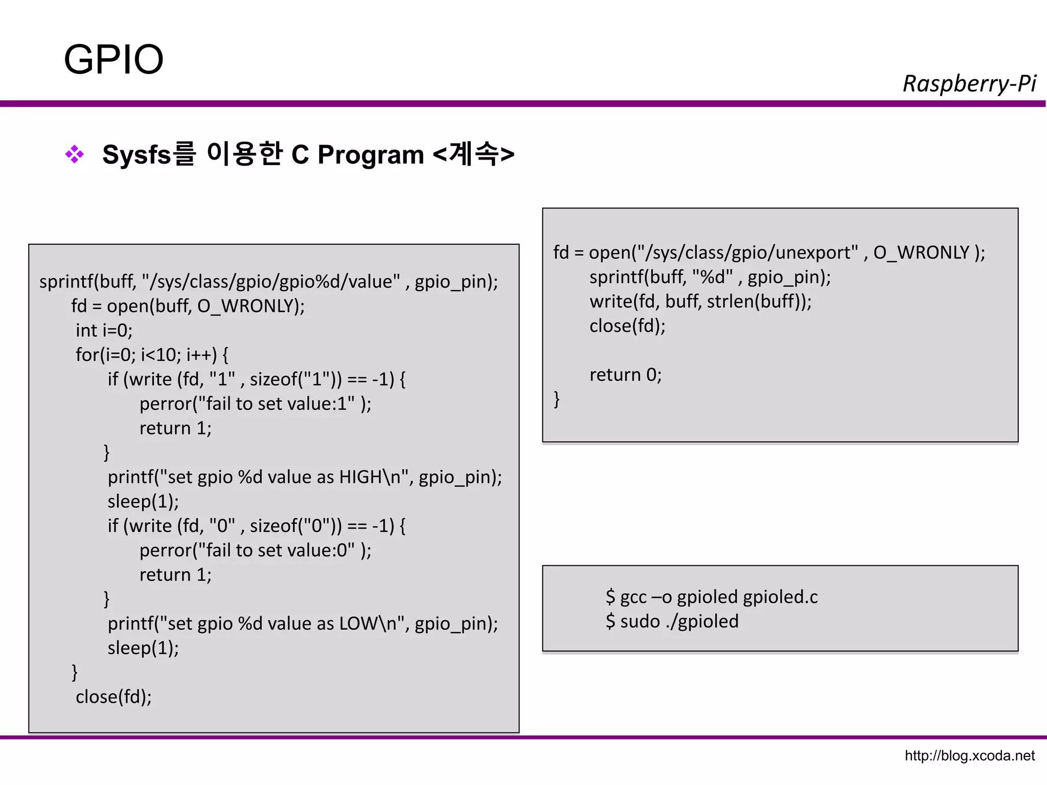
sprintf(buff, "/sys/class/gpio/gpio%d/direction" ,
gpio_pin);
fd = open(buff, O_WRONLY);
if (fd == -1) {
perror("fail to open GPIO Direction File" );
return 1;
}
if (write (fd, "out" , 4) == -1) {
perror("fail to set directionn" );
return 1;
}
close(fd);
#include <stdio.h>
#include <fcntl.h>
#include <unistd.h>
#include <string.h>
int main( int argc, char **argv) {
int gpio_pin = 18;
int fd;
char buff[BUFSIZ];
fd = open("/sys/class/gpio/export", O_WRONLY );
if (fd == -1) {
perror("fail to open export." );
return 1;
}
sprintf(buff, "%d" , gpio_pin);
if (write (fd, buff, sizeof(buff)) == -1) {
perror("fail to export GPIO" );
return 1;
}
close(fd);](https://image.slidesharecdn.com/rpigpio-161029143834/85/Raspberry-PI-GPIO-with-Python-32-320.jpg)
![http://blog.xcoda.net
Raspberry-Pi
GPIO
Rpi.GPIO 기본 함수
import Rpi.GPIO as GPIO
모듈 import
GPIO.setmode(GPIO.BCM or GPIO.BOARD)
GPIO.BCM : Broadcom Soc에서 정의한 번호
GPIO.BOARD : 보드에 핀 순번
GPIO.setup(channel, direction[, intial=state] )
channel : GPIO Pin 번호
direction : GPIO.IN, GPIO.OUT
state : GPIO.HIGH, GPIO.LOW
GPIO.setup(channel, GPIO.IN [, pull_up_down=pud])
pud = GPIO.PUD_UP, GPIO.PUD_DOWN
GPIO.input(channel)
GPIO.output(channel, state)
GPIO.cleanup()
종료전에 자원 반납
https://sourceforge.net/p/raspberry-gpio-python/wiki/Examples/](https://image.slidesharecdn.com/rpigpio-161029143834/85/Raspberry-PI-GPIO-with-Python-36-320.jpg)

![http://blog.xcoda.net
Raspberry-Pi
Digital Output
트랜지스터 스위치 Code
LED Blink와 동일
pin = 18
try:
GPIO.setmode(GPIO.BCM)
GPIO.setup(pin, GPIO.OUT)
while True:
val = input("swtich [on:1, off:0]")
GPIO.output(pin, val)
finally:
print 'clean up'
GPIO.cleanup()](https://image.slidesharecdn.com/rpigpio-161029143834/85/Raspberry-PI-GPIO-with-Python-51-320.jpg)


![http://blog.xcoda.net
Raspberry-Pi
Sensor Modules
DHT-11 Source
Rpi.GPIO로 구현
https://github.com/netikras/r-pi_DHT11/blob/master/dht11.py
def pullData():
global data
global effectiveData
global pin
data = []
effectiveData = []
GPIO.setup(pin,GPIO.OUT)
GPIO.output(pin,GPIO.HIGH)
time.sleep(0.025)
GPIO.output(pin,GPIO.LOW)
time.sleep(0.14)
GPIO.setup(pin, GPIO.IN, pull_up_down=GPIO.PUD_UP)
for i in range(0,1000):
data.append(GPIO.input(pin))
import RPi.GPIO as GPIO
import time
import sys
def bin2dec(string_num):
return str(int(string_num, 2))
data = []
effectiveData = []
bits_min=999;
bits_max=0;
HumidityBit = ""
TemperatureBit = ""
crc = ""
crc_OK = False;
Humidity = 0
Temperature = 0
pin=4
GPIO.setmode(GPIO.BCM)](https://image.slidesharecdn.com/rpigpio-161029143834/85/Raspberry-PI-GPIO-with-Python-86-320.jpg)
![http://blog.xcoda.net
Raspberry-Pi
Sensor Modules
DHT-11 Source
Rpi.GPIO로 구현 <계속>
for i in range(0, 40):
buffer = "";
while(seek < len(data) and data[seek] == 0):
seek+=1;
while(seek < len(data) and data[seek] == 1):
seek+=1;
buffer += "1";
if (len(buffer) < bits_min):
bits_min = len(buffer)
if (len(buffer) > bits_max):
bits_max = len(buffer)
effectiveData.append(buffer);
def analyzeData():
seek=0;
bits_min=9999;
bits_max=0;
global HumidityBit
global TemperatureBit
global crc
global Humidity
global Temperature
HumidityBit = ""
TemperatureBit = ""
crc = ""
while(seek < len(data) and data[seek] == 0):
seek+=1;
while(seek < len(data) and data[seek] == 1):
seek+=1;](https://image.slidesharecdn.com/rpigpio-161029143834/85/Raspberry-PI-GPIO-with-Python-87-320.jpg)
![http://blog.xcoda.net
Raspberry-Pi
Sensor Modules
DHT-11 Source
Rpi.GPIO로 구현 <계속>
def isDataValid():
global Humidity
global Temperature
global crc
print "isDataValid(): H=%d, T=%d, crc=%d"% (int(Humidity),
int(Temperature), int(bin2dec(crc)))
if int(Humidity) + int(Temperature) == int(bin2dec(crc)):
return True;
else:
return False;
def printData():
global Humidity
global Temperature
print "H: "+Humidity
print "T: "+Temperature
for i in range(0, len(effectiveData)):
if (len(effectiveData[i]) < ((bits_max + bits_min)/2)):
effectiveData[i] = "0";
else:
effectiveData[i] = "1";
for i in range(0, 8):
HumidityBit += str(effectiveData[i]);
for i in range(16, 24):
TemperatureBit += str(effectiveData[i]);
for i in range(32, 40):
crc += str(effectiveData[i]);
Humidity = bin2dec(HumidityBit)
Temperature = bin2dec(TemperatureBit)](https://image.slidesharecdn.com/rpigpio-161029143834/85/Raspberry-PI-GPIO-with-Python-88-320.jpg)


![http://blog.xcoda.net
Raspberry-Pi
ADC - SPI
MCP3008로 가변저항 읽기
open(port, dev)
Port : 0
Dev :CE0 =0, CE1=1
xfer2([byte_1, byte_2, byte_3])
byte_1 : 1
byte_2 : channel config
1000 000 : channel 0
byte_3 : 0(ignored)
abc_out
r[0] : ignored
r[1] : 10bit의 최상위 2bit 값
r[2] : 10bit의 하위 8bit 값
import spidev, time
spi = spidev.SpiDev()
spi.open(0,0)
def analog_read(channel):
r = spi.xfer2([1, (8 + channel) << 4, 0])
adc_out = ((r[1]&3) << 8) + r[2]
return adc_out
try:
while True:
reading = analog_read(0)
voltage = reading * 3.3 / 1024
print("Reading=%dtVoltage=%f" % (reading,
voltage))
time.sleep(1)
finally:
spi.close()](https://image.slidesharecdn.com/rpigpio-161029143834/85/Raspberry-PI-GPIO-with-Python-100-320.jpg)


![http://blog.xcoda.net
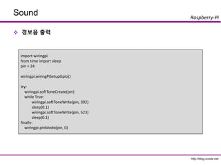
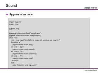
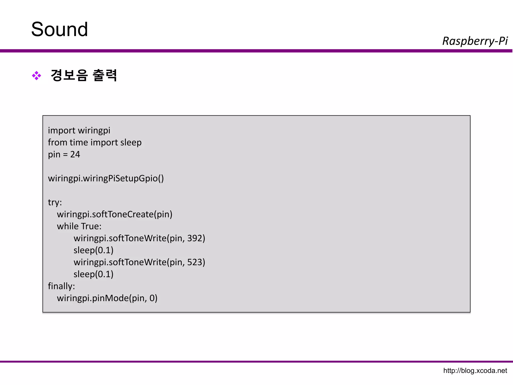
Raspberry-Pi
Sound
반짝반짝 작은별 스케치
import wiringpi
from time import sleep
pin = 24
frequencies = {'c':262, 'd':294, 'e':330, 'f':349, 'g':392, 'a':440, 'b':494}
notes = 'ccggaag ffeeddc ggffeed ggffeed ccggaag ffeeddc'
wiringpi.wiringPiSetupGpio()
try:
wiringpi.softToneCreate(pin)
for i in notes:
if i != ' ':
wiringpi.softToneWrite(pin, frequencies[i])
sleep(0.3)
finally:
wiringpi.pinMode(pin, 0)](https://image.slidesharecdn.com/rpigpio-161029143834/85/Raspberry-PI-GPIO-with-Python-105-320.jpg)
![http://blog.xcoda.net
Raspberry-Pi
Camera
Pycamera Code
import time
import picamera
with picamera.PiCamera() as camera:
try:
camera.start_preview()
while True:
shutter = input('insert key when you are ready to take photo. [photo:1, video:2] ')
now_str = time.strftime("%Y%m%d-%H%M%S")
if shutter == 1:
camera.capture('/home/pi/demo/camera/photo%s.gif' %now_str)
elif shutter == 2:
camera.start_recording('/home/pi/demo/camera/video%s.h264' %now_str)
raw_input('insert key when you want to stop recoding.')
camera.stop_recording()
finally:
camera.stop_preview()](https://image.slidesharecdn.com/rpigpio-161029143834/85/Raspberry-PI-GPIO-with-Python-110-320.jpg)


![http://blog.xcoda.net
Raspberry-Pi
GPIO
Sysfs를 이용한 C Program – gpioled.c
sprintf(buff, "/sys/class/gpio/gpio%d/direction" ,
gpio_pin);
fd = open(buff, O_WRONLY);
if (fd == -1) {
perror("fail to open GPIO Direction File" );
return 1;
}
if (write (fd, "out" , 4) == -1) {
perror("fail to set directionn" );
return 1;
}
close(fd);
#include <stdio.h>
#include <fcntl.h>
#include <unistd.h>
#include <string.h>
int main( int argc, char **argv) {
int gpio_pin = 18;
int fd;
char buff[BUFSIZ];
fd = open("/sys/class/gpio/export", O_WRONLY );
if (fd == -1) {
perror("fail to open export." );
return 1;
}
sprintf(buff, "%d" , gpio_pin);
if (write (fd, buff, sizeof(buff)) == -1) {
perror("fail to export GPIO" );
return 1;
}
close(fd);](https://image.slidesharecdn.com/rpigpio-161029143834/75/Raspberry-PI-GPIO-with-Python-32-2048.jpg)
![http://blog.xcoda.net
Raspberry-Pi
GPIO
Rpi.GPIO 기본 함수
import Rpi.GPIO as GPIO
모듈 import
GPIO.setmode(GPIO.BCM or GPIO.BOARD)
GPIO.BCM : Broadcom Soc에서 정의한 번호
GPIO.BOARD : 보드에 핀 순번
GPIO.setup(channel, direction[, intial=state] )
channel : GPIO Pin 번호
direction : GPIO.IN, GPIO.OUT
state : GPIO.HIGH, GPIO.LOW
GPIO.setup(channel, GPIO.IN [, pull_up_down=pud])
pud = GPIO.PUD_UP, GPIO.PUD_DOWN
GPIO.input(channel)
GPIO.output(channel, state)
GPIO.cleanup()
종료전에 자원 반납
https://sourceforge.net/p/raspberry-gpio-python/wiki/Examples/](https://image.slidesharecdn.com/rpigpio-161029143834/75/Raspberry-PI-GPIO-with-Python-36-2048.jpg)


![http://blog.xcoda.net
Raspberry-Pi
Digital Output
트랜지스터 스위치 Code
LED Blink와 동일
pin = 18
try:
GPIO.setmode(GPIO.BCM)
GPIO.setup(pin, GPIO.OUT)
while True:
val = input("swtich [on:1, off:0]")
GPIO.output(pin, val)
finally:
print 'clean up'
GPIO.cleanup()](https://image.slidesharecdn.com/rpigpio-161029143834/75/Raspberry-PI-GPIO-with-Python-51-2048.jpg)


![http://blog.xcoda.net
Raspberry-Pi
Sensor Modules
DHT-11 Source
Rpi.GPIO로 구현
https://github.com/netikras/r-pi_DHT11/blob/master/dht11.py
def pullData():
global data
global effectiveData
global pin
data = []
effectiveData = []
GPIO.setup(pin,GPIO.OUT)
GPIO.output(pin,GPIO.HIGH)
time.sleep(0.025)
GPIO.output(pin,GPIO.LOW)
time.sleep(0.14)
GPIO.setup(pin, GPIO.IN, pull_up_down=GPIO.PUD_UP)
for i in range(0,1000):
data.append(GPIO.input(pin))
import RPi.GPIO as GPIO
import time
import sys
def bin2dec(string_num):
return str(int(string_num, 2))
data = []
effectiveData = []
bits_min=999;
bits_max=0;
HumidityBit = ""
TemperatureBit = ""
crc = ""
crc_OK = False;
Humidity = 0
Temperature = 0
pin=4
GPIO.setmode(GPIO.BCM)](https://image.slidesharecdn.com/rpigpio-161029143834/75/Raspberry-PI-GPIO-with-Python-86-2048.jpg)
![http://blog.xcoda.net
Raspberry-Pi
Sensor Modules
DHT-11 Source
Rpi.GPIO로 구현 <계속>
for i in range(0, 40):
buffer = "";
while(seek < len(data) and data[seek] == 0):
seek+=1;
while(seek < len(data) and data[seek] == 1):
seek+=1;
buffer += "1";
if (len(buffer) < bits_min):
bits_min = len(buffer)
if (len(buffer) > bits_max):
bits_max = len(buffer)
effectiveData.append(buffer);
def analyzeData():
seek=0;
bits_min=9999;
bits_max=0;
global HumidityBit
global TemperatureBit
global crc
global Humidity
global Temperature
HumidityBit = ""
TemperatureBit = ""
crc = ""
while(seek < len(data) and data[seek] == 0):
seek+=1;
while(seek < len(data) and data[seek] == 1):
seek+=1;](https://image.slidesharecdn.com/rpigpio-161029143834/75/Raspberry-PI-GPIO-with-Python-87-2048.jpg)
![http://blog.xcoda.net
Raspberry-Pi
Sensor Modules
DHT-11 Source
Rpi.GPIO로 구현 <계속>
def isDataValid():
global Humidity
global Temperature
global crc
print "isDataValid(): H=%d, T=%d, crc=%d"% (int(Humidity),
int(Temperature), int(bin2dec(crc)))
if int(Humidity) + int(Temperature) == int(bin2dec(crc)):
return True;
else:
return False;
def printData():
global Humidity
global Temperature
print "H: "+Humidity
print "T: "+Temperature
for i in range(0, len(effectiveData)):
if (len(effectiveData[i]) < ((bits_max + bits_min)/2)):
effectiveData[i] = "0";
else:
effectiveData[i] = "1";
for i in range(0, 8):
HumidityBit += str(effectiveData[i]);
for i in range(16, 24):
TemperatureBit += str(effectiveData[i]);
for i in range(32, 40):
crc += str(effectiveData[i]);
Humidity = bin2dec(HumidityBit)
Temperature = bin2dec(TemperatureBit)](https://image.slidesharecdn.com/rpigpio-161029143834/75/Raspberry-PI-GPIO-with-Python-88-2048.jpg)


![http://blog.xcoda.net
Raspberry-Pi
ADC - SPI
MCP3008로 가변저항 읽기
open(port, dev)
Port : 0
Dev :CE0 =0, CE1=1
xfer2([byte_1, byte_2, byte_3])
byte_1 : 1
byte_2 : channel config
1000 000 : channel 0
byte_3 : 0(ignored)
abc_out
r[0] : ignored
r[1] : 10bit의 최상위 2bit 값
r[2] : 10bit의 하위 8bit 값
import spidev, time
spi = spidev.SpiDev()
spi.open(0,0)
def analog_read(channel):
r = spi.xfer2([1, (8 + channel) << 4, 0])
adc_out = ((r[1]&3) << 8) + r[2]
return adc_out
try:
while True:
reading = analog_read(0)
voltage = reading * 3.3 / 1024
print("Reading=%dtVoltage=%f" % (reading,
voltage))
time.sleep(1)
finally:
spi.close()](https://image.slidesharecdn.com/rpigpio-161029143834/75/Raspberry-PI-GPIO-with-Python-100-2048.jpg)
![http://blog.xcoda.net
Raspberry-Pi
Sound
반짝반짝 작은별 스케치
import wiringpi
from time import sleep
pin = 24
frequencies = {'c':262, 'd':294, 'e':330, 'f':349, 'g':392, 'a':440, 'b':494}
notes = 'ccggaag ffeeddc ggffeed ggffeed ccggaag ffeeddc'
wiringpi.wiringPiSetupGpio()
try:
wiringpi.softToneCreate(pin)
for i in notes:
if i != ' ':
wiringpi.softToneWrite(pin, frequencies[i])
sleep(0.3)
finally:
wiringpi.pinMode(pin, 0)](https://image.slidesharecdn.com/rpigpio-161029143834/75/Raspberry-PI-GPIO-with-Python-105-2048.jpg)

![http://blog.xcoda.net
Raspberry-Pi
Camera
Pycamera Code
import time
import picamera
with picamera.PiCamera() as camera:
try:
camera.start_preview()
while True:
shutter = input('insert key when you are ready to take photo. [photo:1, video:2] ')
now_str = time.strftime("%Y%m%d-%H%M%S")
if shutter == 1:
camera.capture('/home/pi/demo/camera/photo%s.gif' %now_str)
elif shutter == 2:
camera.start_recording('/home/pi/demo/camera/video%s.h264' %now_str)
raw_input('insert key when you want to stop recoding.')
camera.stop_recording()
finally:
camera.stop_preview()](https://image.slidesharecdn.com/rpigpio-161029143834/75/Raspberry-PI-GPIO-with-Python-110-2048.jpg)


![[IoT] MAKE with Open H/W + Node.JS - 4th](https://cdn.slidesharecdn.com/ss_thumbnails/iotoshwnodejslesson4-150419161845-conversion-gate02-thumbnail.jpg?width=600ounds&width=560&fit=bounds)


![[IoT] MAKE with Open H/W + Node.JS - 1st](https://cdn.slidesharecdn.com/ss_thumbnails/iotoshwnodejslesson1-150218080320-conversion-gate02-thumbnail.jpg?width=600ounds&width=560&fit=bounds)


