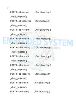
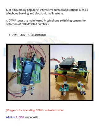
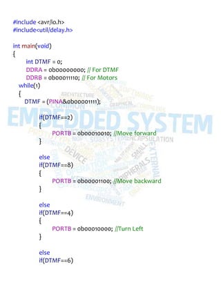
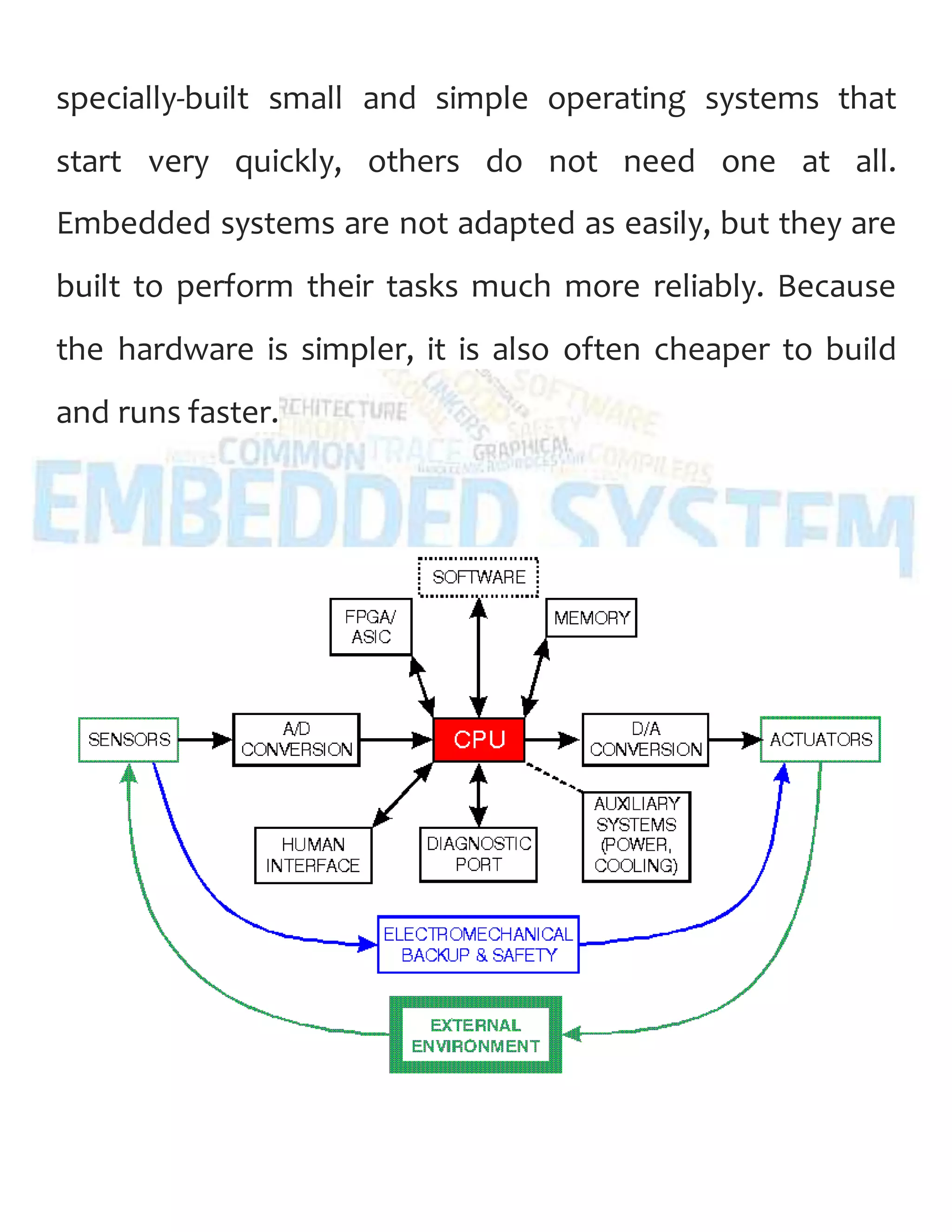
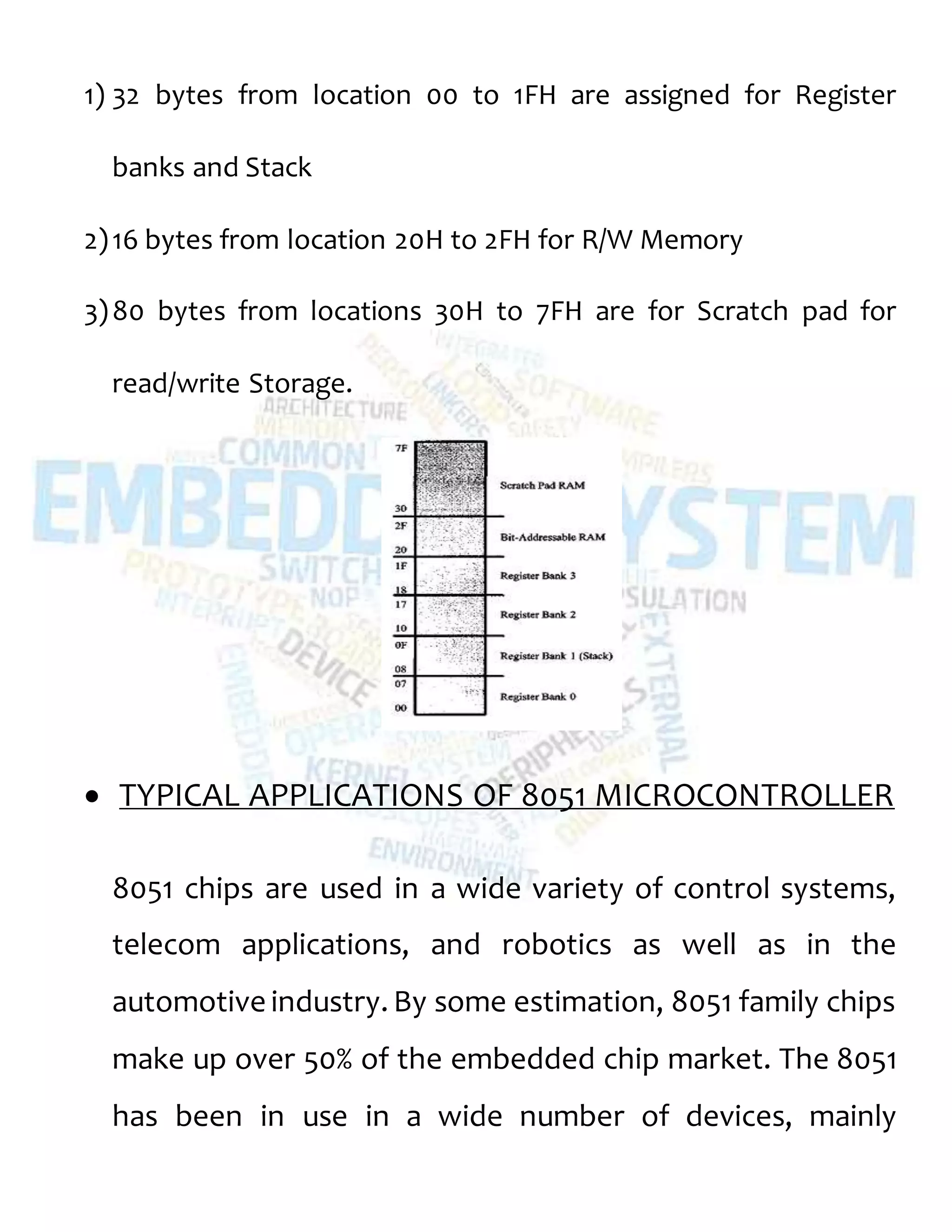
KEMBAR78
Project Report on Embedded Systems | DOCX
PROJECT REPORT
‘ADVANCED
EMBEDDED SYSTEMS’
SUMMER TRAINING 2014
Submitted By:
SUHANI SINGH
ECE – III Yr.
ACKNOWLEDEMENTS
I owe a debt of gratitude to Mr. Guru Prabhat, H.O.D of
our department, for providing us an opportunity to
pursue this training and inspiring us to conceive the same.
It is also my duty to record my thankfulness to Mr. Pankaj
Singh, our trainer for the course, who continually and
convincingly conveyed excitement in regard to teaching.
Without his guidance and persistent help, this successful
learning process would not have been possible.
I would also thank my colleagues for their help, whenever
I needed it.
SUHANI SINGH
Student, ECE Department
ABSTRACT
This report contains the details of the content that was
taught during the summer training. It includes the
description of the theoretical as well as the practical
content that we learnt during the training.
It also includes all the hardware and software details of
the projects undertaken during the course.
CONTENTS
1. Introduction
2. Embedded Systems
3. Examples of Embedded Systems
4. Common features of an Embedded System
5. Microprocessors
6. Microcontrollers
7. Comparison between Microprocessor and
Microcontroller
8. The 8051 Architecture
9. Atmel AVR
10. Interfacing
1. Introduction
Microcontroller are widely used in Embedded System
products. An Embedded product uses the
microprocessor(or microcontroller) to do one task & one
task only. A printer is an example of Embedded system
since the processor inside it perform one task only namely
getting the data and printing it. Although microcontroller
are preferred choice for many Embedded systems, There
are times that a microcontroller is inadequate for the task.
For this reason in recent years many manufactures of
general purpose microprocessors such as INTEL,
Motorolla, AMD & Cyrix have targeted their
microprocessors for the high end of Embedded
market.One of the most critical needs of the embedded
system is to decrease power consumptions and space.
This can be achieved by integrating more functions into
the CPU chips. All the embedded processors have low
power consumptions in additions to some forms of
I/O,ROM all on a single chip. In higher performance
Embedded system the trend is to integrate more & more
function on the CPU chip & let the designer decide which
feature he/she wants to use.
2. Embedded Systems
An Embedded system is a computer that has been built to
solve only a few very specific problems and is not easily
changed. An embedded system usually does not look like
a computer, often there is no keyboard or monitor or
mouse. But like any computer it has
a processor and software, input and output. The
word embedded means it is built into the system. It is a
permanent part in a bigger system. For example, a
controller is embedded in an elevator and tells the motor
to move the elevator to different floors based on buttons
that are pushed. A decoder is embedded in a satellite
television set-top box to read a signal from the dish and
send something that a TV understands. Often this type of
system must do its work in a specific amount of time. This
is called real-time computing. If a set-top box got
interrupted to do another task, you would see a bad
picture on the TV, for example.
Because many embedded systems are built to only
perform a few very specific tasks they often do not need a
full operating system. Some embedded systems use
specially-built small and simple operating systems that
start very quickly, others do not need one at all.
Embedded systems are not adapted as easily, but they are
built to perform their tasks much more reliably. Because
the hardware is simpler, it is also often cheaper to build
and runs faster.
3. Examples of Embedded
Systems
Embedded systems are used everywhere in modern life
and there are many examples of their use, including:
 A telecommunication system uses them
for telephones, cell phone network, and wifi routers.
 Consumer electronics include clock radios, MP3
players, mobile phones, video game consoles, digital
cameras, DVD players, GPS receivers, home security
systems, and printers.
 Household appliances, like microwave ovens, washing
machines and dishwashers have embedded systems.
 Transportation uses embedded systems for everything
from locomotives for trains, airplanes and automobiles.
 Industry uses electric motors with electronic motor
controllers, card readers and CNC machines which
automatically make metal parts.
 Medical devices like defibrillators, automated blood
pressure readers, and automated insulin pumps.
 Military devices, like walkie-talkies, satellites and the
guiding systems for missiles.
4. Common Features of an
Embedded System
 Embedded systems are designed to do a specific task,
unlike general purpose computers.
 It does not look like a computer - there may not be a full
monitor or a keyboard.
 Many embedded systems must be able to do things
in real-time - in a short amount of time (almost instantly
from a human view).
 Many embedded systems must be very safe and
reliable, especially for medical devices
or avionics controlling airplanes.
 Starts very quickly. People don't want to wait a minute
or two for their car to start or emergency equipment to
start.
 It uses a special operating system (or sometimes a very
small home-made OS) that helps meet these
requirements called a real-time operating system, or
RTOS.
 The program instructions written for embedded
systems are referred to as firmware, and are stored in
read-only memory or flash memory chips. They run with
limited computer hardware resources: little memory,
small or non-existent keyboard and/or screen.
Embedded systems are not always standalone devices.
Sometimes they are built as a set, like the various parts of
a car - the radio, the throttle control, the pollution control,
etc. Sometimes they can communicate to the internet or a
cell-phone network and they may have a USB reader or
other connections.
5. Microprocessors
A microprocessor incorporatesthe functionsof
a computer'scentralprocessing unit (CPU) on a
single integrated circuit (IC),or at most a few integrated
circuits.All modern CPUs are microprocessors making
the micro- prefix redundant. The microprocessor isa
multipurpose, programmable device that accepts digitaldata as
input, processes it according toinstructionsstored in its
memory, and providesresults as output. It is an example
of sequentialdigitallogic, as it has internalmemory.
Microprocessorsoperate on numbersand symbols represented
in the binary numeralsystem.
The integration ofa whole CPU ontoa single chip or on a few
chips greatly reduced the cost of processing power. The
integratedcircuit processor was produced in large numbersby
highly automated processes, so unit cost was low. Single-chip
processors increase reliability as there are many fewer electrical
connectionsto fail. As microprocessor designsget faster, the
cost of manufacturing a chip (with smaller componentsbuilt on
a semiconductor chipthe same size) generally staysthe same.
 Intel 4004 is generally regarded asthe first commercially
available microprocessor,and cost $60.The first known
advertisement for the 4004 is dated November 15, 1971 and
appeared in ElectronicNews.The project that produced the
4004 originatedin 1969, when Busicom, a Japanese
calculator manufacturer, asked Intel to build a chipset for
high-performancedesktopcalculators. Busicom's original
design called for a programmable chipset consisting of
seven different chips.
6. Microcontrollers
A microcontroller (sometimesabbreviated µC, uC or MCU) is a
small computer on a single integratedcircuit containing a
processor core, memory and
programmable input/output peripherals. Programmemory in
the form of NOR flash or OTP ROM is also often included on
chip, as well as a typically small amount of RAM.
Microcontrollersare designed for embedded applications, in
contrast to the microprocessorsused in personal computersor
other generalpurpose applications.
Microcontrollers are used in automatically controlled
products and devices, such as automobile engine control
systems, implantable medical devices, remote controls,
office machines, appliances and other embedded
systems. By reducing the size and cost compared to a
design that uses a separate microprocessor, memory and
input output devices, microcontrollers make it economical
to digitally control even more devices and processes.
Figure shows the block diagramof a typical microcontroller. The
design incorporates all of the features found in micro-
processor CPU: ALU, PC, SP, and registers. It also added the
other features needed to make a complete computer: ROM,
RAM, parallel I/O, serial I/O, counters, and clock circuit.
7. Comparison between
Microprocessor and
Microcontroller
The microprocessor must have many additional parts to be
operationalas a computer whereas microcontroller requires no
additional external digital parts.
1. The prime use of microprocessor is to read data, perform
extensive calculations on that data and store them in the mass
storage device or display it. The prime functions of
microcontroller is to read data, perform limited calculations on
it, control its environment based on these data. Thus the
microprocessor is said to be general-purpose digital computers
whereas the microcontroller are intend to be special purpose
digital controller.
2. Microprocessor need many opcodes for moving data from
the external memory to the CPU, microcontroller may require
just one or two, also microprocessor may have one or twotypes
of bit handling instructions whereas microcontrollers have
many.
3. Thus microprocessor is concerned with the rapid movement
of the code and data from the external addresses to the chip,
microcontroller is concerned with the rapid movement of the
bits within the chip.
4. Lastly, the microprocessor design accomplishes the goal of
flexibility in the hardware configuration by enabling large
amounts of memory and I/O that could be connected to the
address and data pins on the IC package. The microcontroller
design uses much more limited.
8. The 8051 Architecture
The Intel8051 is an 8-bit microcontrollerwhich meansthat most
available operationsare limited to 8 bits. There are 3 basic
"sizes" of the 8051: Short, Standard, and Extended. The Short
and Standard chips are often available in DIP (dual in-line
package) form, but the Extended 8051 models often have a
different formfactor, and are not "drop-in compatible".
 BLOCKDIAGRAM
Some of the features that have made the 8051 popular are:
 4 KB on chip program memory.
 128 bytes on chip data memory (RAM).
 4 register banks.
 8-bit data bus
 16-bit address bus
 32 general purpose registers each of 8 bits
 16 bit timers (usually 2, but may have more, or less).
 3 internal and 2 external interrupts.
 Bit as well as byte addressable RAM area of 16 bytes.
 Four 8-bit ports, (short models have two 8-bit ports).
 16-bit program counter and data pointer.
 1 Microsecond instruction cycle with 12 MHz Crystal.
 8051 models may also have a number of special, model-
specific features, such as UARTs, ADC, Op-Amps, etc...
 PINOUT DESCRIPTION
4 Ports: Pins 1-8 for PORT 1
Pins 10-17 for PORT 3
Pins 21-28 for PORT 2
Pins 32-39 for PORT 0
RST (PIN 9): It is the resetting pin for the device (8051).
XTAL (PIN 18): It is the output of inverting amplifier which is a
part of the on-chip oscillator. When external clock is used, it is
left unconnected.
XTAL (PIN19): It is the input to the inverting amplifier which is a
part of the on-chip oscillator circuit. When external clock is
used, it is connected to the external oscillator.
VSS (PIN 20): It is the circuit ground. All the voltage are
specified with respect to it.
VCC (PIN40): It is for the power supply, +5V.
PSEN (PIN 29): It is program store enable. It is output control
signal. It is a read strobe to external program memory.
ALE (PIN 30): It is the Address Latch Enable signal.
 RAM MEMORY SPACE ALLOCATION
There are 128 bytes of RAM in 8051 where the addresses are
assigned from 00H to 7FH.
The 128 bytes are divided into different segments as:
1) 32 bytes from location 00 to 1FH are assigned for Register
banks and Stack
2)16 bytes from location 20H to 2FH for R/W Memory
3)80 bytes from locations 30H to 7FH are for Scratch pad for
read/write Storage.
 TYPICAL APPLICATIONS OF 8051 MICROCONTROLLER
8051 chips are used in a wide variety of control systems,
telecom applications, and robotics as well as in the
automotive industry. By some estimation, 8051 family chips
make up over 50% of the embedded chip market. The 8051
has been in use in a wide number of devices, mainly
because it is easy to integrate into a project or build a
device around. The following are the main areas of focus:
1. Energy Management: Efficient metering systems help in
controlling energy usage in homes and industrial
applications. These metering systems are made capable by
incorporating microcontrollers.
2. Touch screens: A high number of microcontroller
providers incorporate touch-sensing capabilities in their
designs. Portable electronics such as cell phones, media
players and gaming devices are examples of
microcontroller-based touch screens.
3. Automobiles: The 8051 finds wide acceptance in
providing automobile solutions. They are widely used in
hybrid vehicles to manage engine variants. Additionally,
functions such as cruise controland anti-brake system have
been made more efficient with the use of microcontrollers.
So the microcontroller 8051has great advantage in the field
of the automobiles.
4. Medical Devices: Portable medical devices such as blood
pressure and glucose monitors
5. Microcontrollers are used to display data, thus providing
higher reliability in providing medical results.
 8051 DEVELOPMENT BOARD
9. ATMEL AVR
AVR stands for Advanced Virtual RISC or Automatic Voltage
Regulator.
The AVR is a modified Harvard architecture 8-bit RISC single
chip microcontroller which was developed by Atmel in 1996.
The AVR was one of the first microcontroller families to use on-
chip flash memory for storage
 ATmega16
ATmega16 is an 8-bit high performance microcontroller of
Atmel’s Mega AVR family with low power consumption.
 Atmega16 is based on enhanced RISC (Reduced Instruction
Set Computing).
 It contains 131 powerful instructions.
 ATmega16 has 16 KB programmable flash memory, static
RAM of 1 KB and EEPROM of 512 Bytes.
 ATmega16 is a 40 pin microcontroller.
 PIN DIAGRAM
The figure below shows the pin diagram of Atmega16.
Atmega16 contains a total of 40 Pins.
o 4 Ports -> PORT A (8 Pins)
-> PORT B (8 Pins)
-> PORTC (8 Pins)
-> PORTD (8 Pins)
o 2 Power Pins for- AC supply and DC supply
AC Power supply pin: AVCC (PIN 30)
DC Power supply pin: VCC (PIN 10)
o 2 Pins to connect crystal oscillator
o 2 Ground Pins (GND)
o 1 Reference Pin (AREF)
o 1 Reset Key (RESET)
All the ports, Port A, B, C and D have their own functions as
described in the figure. The LEDs, Motors or any output
determining devices can be connected on any of the 4
Ports. But as we take a careful look at the Microcontroller
board, we see that, the port for the “Sensors” if fixed i.e.
PORTB.
Picture above shows the ATmega16 development board
provided by Revert Technologies during the training.
The softwares used for interfacing with ATmega16 are:
 WINAVR
 Atmel Studio 6
 SinaProg
10. Interfacing
1. LED INTERFACING
 Overview
Like a normal diode, an LED consists of a chip of semiconducting
material impregnated, or doped, with impurities to create a p-n
junction. As in other diodes, current flows easily from the p-side, or
anode, to the n-side, or cathode, but not in the reverse direction.
Charge-carriers—electrons and holes—flow into the junction from
electrodes with different voltages.
The materials used for an LED have a direct band gap with energies
corresponding to near-infrared, visible or near-ultraviolet light. LED
development began with infrared and red devices made with gallium
arsenide. Advances in materials science have made possible the
production of devices with ever-shorter wavelengths, producing light in
a variety of colors. Conventional LEDs are made from a variety of
inorganic semiconductor materials, producing the following colors:
Aluminum gallium arsenide (AlGaAs) — Red and Infrared
Aluminum gallium phosphide (AlGaP) — Green
Aluminum gallium indium phosphide (AlGaInP) — High-brightness
Orange-red, Orange, Yellow, and Green
Gallium arsenide phosphide (GaAsP) — Red, Orange-Red, Orange, and
Yellow
Gallium phosphide (GaP) — Red, Yellow and Green
Gallium nitride (GaN) — Green, Pure Green (or Emerald green), and
Blue
// Program to blink all the 8 LED’s on the board.
#include<avr/io.h>
#include<util/delay.h>
int main(void)
{
DDRB=0xFF; //Initialize all the pins of PORTB high
while(1)
{
PORTB=0xFF; //LED’s on PORTB ‘ON’
_delay_ms(150);
PORTB=0x00; //LED’s on PORTB ‘OFF’
_delay_ms(150);
}
return ;
}
*The above program, when burned on the development board, makes
all the LED’s blink together and then turn them all OFF together.
 LED BLINKING
// Program for alternate blinking of LED’s.
#include<avrio.h>
#include<utildelay.h>
int main(void)
{
DDRB=0xFF; //All pins of PORTB set high
while(1)
{
for(int i=2; i<257; i=i*4)
{
PORTB=i;
_delay_ms(1500);
}
for(int j=1; j<129; j=j*4)
{
PORTB=j;
_delay_ms(1500);
}
}
return;
}
Note: The sequence of blinking the LEDs has to be controlled by the
user by giving the appropriate commands in the program. In the above
program, the sequence of blinking of the LED’s is 2-4-6-8-1-3-5-7.
2. SEVEN SEGMENT DISPLAY INTERFACING
 OVERVIEW
 What is seven segment display?
A seven segment display is an electronic device used to display numeric
digits from 0 to 9 and some hexadecimal numbers from A to F. A seven
segment display is a combination of LED’s in such a manner that one
can display numbers and some alphabets on it by controlling its LED’s.
The LED’s are connected in such a manner that is appears as digit 8.
Seven segment displays are used in digital clocks, digital electronic
meters and many other electronic devices for displaying numeric
values. These are used as counters to display counting from 0-99. They
are also used in CD and DVD players.
 TYPES OF SEVEN SEGMENT DISPLAYS
There are two types of seven segment displays:
1. Common Cathode – All the LED’s are connected in common and are
directed to ground. The signal is given to all the eight anode pins in
order to get the desired pattern. The h pin is used for decimal point.
2. Common Anode - The anode of all LED’s are connected in common
and directed to a +5V supply. Then by applying ground or logic zero to
a particular segment connection, the appropriate segment will light up.
An additional resistor must be added to the circuit to limit the amount
of current flowing through each LED Segment.
 CONNECTION OF SEVEN SEGMENT DISPLAY USING
ATmega16
The image below shows seven segment display (common
cathode) connected to atmega16 development board.
// Program to display numeric values from 0-9 on a seven
segment display
#include<avr/io.h>
#include<util/delay.h>
int main(void)
{
DDRB = 0b11111111; // PORTB defined as output port
while(1)
{
PORTB = 0b00111111; //for displaying 0
_delay_ms(1000);
PORTB = 0b00000110; //for displaying 1
_delay_ms(1000);
PORTB = 0b01011011; //for displaying 2
_delay_ms(1000);
PORTB = 0b01001111; //for displaying 3
_delay_ms(1000);
PORTB = 0b01100110; //for displaying 4
_delay_ms(1000);
PORTB = 0b01101101; //for displaying 5
_delay_ms(1000);
PORTB = 0b01111101; //for displaying 6
_delay_ms(1000);
PORTB = 0b00000111; //for displaying 7
_delay_ms(1000);
PORTB = 0b01111111; //for displaying 8
_delay_ms(1000);
PORTB = 0b01101111; //for displaying 9
_delay_ms(1000);
}
return;
}
3. LCD INTERFACING
 OVERVIEW
A brief introduction of LCD (Liquid Crystal Display)
A liquid-crystal display (LCD) is a flat panel display, electronic
visual display, or video display that uses the light modulating
properties of liquid crystals. Liquid crystals do not emit light
directly.
LCDs are available to display arbitrary images (as in a general-
purpose computer display) or fixed images which can be displayed
or hidden, such as preset words, digits, and 7-segment displays as
in a digital clock. They use the same basic technology, except that
arbitrary images are made up of a large number of small pixels,
while other displays have larger elements.
LCDs are used in a wide range of applications including computer
monitors, televisions, instrument panels, aircraft cockpit displays,
and signage. They are common in consumer devices such as video
players, gaming devices, clocks, watches, calculators,and
telephones, and have replaced cathode ray tube (CRT) displays in
most applications. They are available in a wider range of screen
sizes than CRT and plasma displays, and since they do not use
phosphors, they do not suffer image burn-in. LCDs are, however,
susceptible to image persistence.
 PIN DESCRIPTION
The pinout diagram of an LCD is shown below:
The pinout description of each pin is shown in the following image:
Note:
 RS 0 = Instruction Input 1 = Data input
 R/W 0 = Write to LCD Module 1 =Read from LCD Module
 EN Enable signal always goes high to low (1-0)
 Commonly used LCD Command Codes
 CONNECTIONS FOR DISPLAYING CHARACTERS ON
LCD
Image below shows the proteus design for displaying characters on
LCD:
The LCD is interfaced using atmega16 microcontroller. This
microcontroller has 40 pins with 4 8-bits ports. Here, PORTD is used as
output port which is connected to the data pins of LCD.
The control pins (pins 4-6) are controlled by pins PC0, PC1 andPC2 of
PORTC.
// Program to display character ‘A’ on LCD
#include<avr/io.h>
#include<util/delay.h>
#define RS PC0 //for Register Select
#define RW PC1 //for Data read and write
#define EN PC2 //for Enable pin
void cmd (unsigned char a) // function for sending commands
{
PORTD = a;
PORTC&=(1<<rs);
PORTC&=(1<<rw);
PORTC|=(1<<en);
_delay_ms(150);
PORTC&=(1<<en);
}
void data (unsigned char a) //function for sending data to data reg
{
PORTD = a;
PORTC|=(1<<rs);
PORTC&=(1<<rw);
PORTC|=(1<<en);
_delay_ms(150);
PORTC&=(1<<en);
}
void main()
{
DDRD = 0xFF; //PORTD as output port
DDRC = oxFF; //PORTC as input port
cmd(0x38); // use 8 bit mode of lcd display
cmd(0x0E); //command for ON the lcd
while(1)
{
Cmd(0x80); //put cursor at 1st
position
data(‘A’); //passing string value for displaying
}
}
4. MOTORS AND SENSORS INTERFACING
 OVERVIEW
MOTORS
A motor is a device that creates motion. It may refer to an
engine of some kind. It converts electrical energy into
mechanical energy.
 TYPES OF MOTORS
1. AC Motor
AC Motor is an electrical motor driven by alternatingcurrent (AC). It
commonly consists of two basic parts, an outside stationary stator
having coils supplied with alternating current to produce a rotating
magnetic field, and an inside rotor connected to the output shaft that
is given a torque by the rotating field.
There are two main types of ac motors, depending on the type of rotor
used. They are induction motors and synchronous motors. Other types
of motors include eddy current motors, AC/DC mechanically
commutated machines, etc.
2. DC MOTORS
A DC Motor relies on the fact that like magnetic poles
repel and unlike magnetic poles attract each other.
A simple DC motor typically has a stationary set of magnetsin
the stator and an armature with a seriesof two or more
windingsof wire wrapped in insulated stack slots around iron
pole pieces (called stack teeth) with the ends of the wires
terminatingon a commutator. Since the series-wound DC motor
develops its highest torque at low speed, it is often used in
traction applicationssuch as electriclocomotives, and trams.
The DC motor was the mainstay of electric traction driveson
both electricand diesel-electriclocomotives, street-cars/trams
and diesel electricdrilling rigsfor many years.
If externalpower is applied to a DC motor it acts as a DC
generator,a dynamo.
3. STEPPER MOTORS
A stepper motor (or step motor) is a brushless DC electric motor that
divides a full rotation into a number of equal steps. The motor's
position can then be commanded to move and hold at one of these
steps without any feedback sensor (an open-loop controller), as long
as the motor is carefullysized to the application.
Switched reluctance motors are very large stepping motors with a
reduced pole count, and generally are closed-loop commutated.
TYPES OF STEPPER MOTORS
There are four main types of stepper motors:
1. Permanent magnet stepper (can be subdivided into 'tin-can' and
'hybrid', tin-can being a cheaper product, and hybrid with higher
quality bearings, smaller step angle, higher power density)
2. Hybrid synchronous stepper
3.Variable reluctance stepper
4.Lavet type stepping motor
Permanent magnet motors use a permanent magnet (PM) in the rotor
and operate on the attraction or repulsion between the rotor PM and
the stator electromagnets. Variable reluctance(VR) motors have a
plain iron rotor and operate based on the principle that minimum
reluctance occurs with minimum gap, hence the rotor points are
attracted toward the stator magnet poles. Hybrid stepper motors are
named because they use a combination of PM and VR techniques to
achieve maximum power in a small package size.
4. SERVO MOTORS
A servomotor is a rotary actuator that allows for precise control of
angular position, velocity and acceleration. It consists of a suitable
motor coupled to a sensor for position feedback. It alsorequires a
relatively sophisticated controller, often a dedicated module designed
specifically for use with servomotors.
Servomotors are not a specific class of motor although the
term servomotor is often used to refer to a motor suitable for use in a
closed-loop control system.
Servomotors are used in applications such as robotics, CNC machinery
or automated manufacturing.
SENSORS
A sensor is a converter that measures a physical quantity and converts
it into a signal which can be read by an observer or by an (today
mostly electronic) instrument. For example, a mercury-in-glass
thermometer converts the measured temperature into expansion and
contraction of a liquid which can be read on a calibrated glass tube.
A thermocouple converts temperature to an output voltage which can
be read by a voltmeter.For accuracy, most sensors
are calibrated against known standards.
Sensors are used in everyday objects such as touch-sensitive elevator
buttons (tactile sensor) and lamps which dim or brighten by touching
the base. There are also innumerable applications for sensors of which
most people are never aware. The most widely used sensors measure
temperature, pressure or flow. Applications include manufacturingand
machinery, airplanes and aerospace, cars, medicine and robotics.
TYPES OF SENSORS
1. IR SENSOR
An infrared sensor is an electronic instrument that is used to sense
certain characteristicsof its surroundings by either emitting and/or
detecting infrared radiation. It is also capable of measuring heat of an
object and detecting motion. Infrared waves are not visible to the
human eye.
Infrared technology is found in many of our everyday products. For
example, TV has an IR detector for interpreting the signal from the
remote control. Key benefits of infrared sensors include low power
requirements, simple circuitry, and their portable feature.
 TYPES OF IR SENSORS
Infra-red sensors are broadly classified into two types:
 Thermal infrared sensors – These use infrared energy as heat. Their
photo sensitivity is independent of wavelength. Thermal detectors
do not require cooling; however, they have slow response times
and low detection capability.
 Quantum infrared sensors – These provide higher detection
performance and faster response speed. Their photo sensitivity is
dependent on wavelength. Quantum detectors have to be cooled
so as to obtain accuratemeasurements. The only exception is for
detectors that are used in the near infrared region.
 APPLICATIONS
The following are the key application areas of infrared sensors:
 Tracking and art history
 Climatology, meteorology, and astronomy
 Thermography, communications, and alcohol testing
 Heating, hyperspectral imaging, and night vision
 Biological systems, photobiomodulation, and plant health
 Gas detectors/gas leak detection
 Water and steel analysis, flame detection
 Anesthesiology testing and spectroscopy
 Petroleum exploration and underground solution
 Rail safety.
2. TEMPERATURE SENSOR
Temperature sensors are devices used to measure the temperatureof
a medium. There are 2 kinds on temperature sensors: 1) contact
sensors and 2) noncontact sensors. However, the 3 main types are
thermometers, resistance temperature detectors, and thermocouples.
All three of these sensors measure a physical property (i.e. volume of a
liquid, current through a wire), which changes as a function of
temperature. In addition to the 3 main types of temperature sensors,
there are numerous other temperature sensors available for use.
Contact Sensors
Contact temperature sensors measure the temperature of the object
to which the sensor is in contact by assuming or knowing that the two
(sensor and the object) are in thermal equilibrium, in other words,
there is no heat flow between them.
Examples (further description of each example provide below)
 Thermocouples
 Resistance Temperature Detectors (RTDs)
 Full System Thermometers
 Bimetallic Thermometers
Noncontact Sensors
Most commercial and scientific noncontact temperature sensors
measure the thermalradiant power of the Infrared or Optical radiation
received from a known or calculated area on its surface or volume
within it.
 A TEMPERATURE SENSOR
3. PROXIMITY SENSOR
A proximity sensor is a sensor able to detect the presence of nearby
objects without any physical contact.
A proximity sensor often emits an electromagnetic field or a beam
of electromagnetic radiation (infrared, for instance), and looks for
changes in the field or return signal. The object being sensed is often
referred to as the proximity sensor's target. Different proximity sensor
targets demand different sensors. For example,
a capacitive or photoelectric sensor might be suitable for a plastic
target; an inductive proximity sensor always requires a metal target.
The maximum distance that this sensor can detect is defined "nominal
range". Some sensors have adjustments of the nominal range or
means to report a graduated detection distance.
 APPLICATIONS
Parking sensors, systems mounted on car bumpers that sense
distance to nearby cars for parking
Ground proximity warning system for aviation safety
Vibration measurements of rotating shafts in machinery
Top dead centre (TDC)/camshaft sensor in reciprocating engines.
Sheets break sensing in paper machine.
Anti-aircraftwarfare
Roller coasters
Conveyor systems
Beverage and food can making lines
Mobile devices
o Touch screens that come in close proximity to the face
o Attenuating radio power in close proximity to the body, in
order to reduce radiation exposure
//Program to drive DC Motors
#include<avr/io.h>
#include<util/delay.h>
void main()
{
DDRB=0b00011110;
while(1)
{
PORTB=0b00010010; //forward motion
_delay_ms(50000);
PORTB=0b00001100; //backward motion
_delay_ms(50000);
PORTB=0b00000010; //Right turn
_delay_ms(50000);
PORTB=0b00010000; //left turn
_delay_ms(50000);
}
}
 LINE FOLLOWER
A line follower robot is a machine that can follow a path. The path can
be visible like a black or white line or can be multi-colored. From
industrial point of view, line following robots have been implemented
in semi to fully autonomous plants.
Line following robots have many practical applications like automated
cars running on roads with embedded magnets; guidance systems for
industrial robots moving on floors, defense applications etc.
//Program for line follower robot using atmega16
#include <avr/io.h>
int main(void)
{
DDRB = 0b00000000; // For Sensors
DDRD = 0b00001111; // For Motors
int ls=0, rs=0;
while(1)
{
ls = (PINB&0b00000001); // Left Sensor at PB0
rs = (PINB&0b00000010); // Right Sensor at PB1
if((ls==0b00000000)&(rs==0b00000000))
{
PORTD = 0b00000000; // Stop the motors
ls=0;
rs=0;
}
if((ls==0b00000001)&(rs==0b00000000))
{
PORTD = 0b00001000; // Turn Right
ls=0;
rs=0;
}
if((ls==0b00000000)&(rs==0b00000010))
{
PORTD = 0b00000001; // Turn Left
ls=0;
rs=0;
}
if((ls==0b00000001)&(rs==0b00000010))
{
PORTD = 0b00001001; // Move Forward
ls=0;
rs=0;
}
}
return 0;
}
 EDGE AVOIDER
Edge avoider is a mobile device, which senses and avoids the absence
of surface below it. This concept was designed to protect the robot
from falling.
This technology has been suggested for running busses and other
mass transit systems and may end up as a part of autonomous cars
navigating the freeway.
//Program for Edge Avoider robot using atmega16
#include <avr/io.h>
#include<util/delay.h>
#define F_CPU 100000UL
int main(void)
{
DDRB = 0b00000000; // Input Port for Sensors
DDRD = 0b00011110; // Output Port for Motors
int ls=1, rs=1;
while(1)
{
ls = (PINB&0b00000001); // Left Sensor at PB0
rs = (PINB&0b00001000); // Right Sensor at PB3
if((ls==0b00000001)&(rs==0b00001000))
{
PORTD = 0b00010010; // Move Forward
}
if((ls==0b00000000)&(rs==0b00000000))
{
PORTD = 0b00001100; // Move Back
_delay_ms(2000);
PORTD = 0b00010000; // Turn Right
_delay_ms(2000);
}
}
return 0;
}
5. DTMF INTERFACING
DTMF stands for Dual Tone Multi-frequency Signaling.
DTMF is the generic name for pushbutton telephone signaling
equivalent to the Bell System’s Touchtone. DTMF signaling is quickly
replacing dial-pulse signaling in telephone networks worldwide.
 APPLICATIONS OF DTMF
1. DTMF is used for telecommunication signaling over analog telephone
lines in the voice frequency band between telephone headsets and
other communication devices.
2. It is becoming popular in interactive control applications such as
telephone banking and electronic mail systems.
3. DTMF tones are mainly used in telephone switching centres for
detection of called/dialed numbers.
 DTMF CONTROLLEDROBOT
//Program for operating DTMF controlled robot
#define F_CPU 1000000UL
#include <avr/io.h>
#include<util/delay.h>
int main(void)
{
int DTMF = 0;
DDRA = 0b00000000; // For DTMF
DDRB = 0b00011110; // For Motors
while(1)
{
DTMF = (PINA&0b00001111);
if(DTMF==2)
{
PORTB = 0b00010010; //Move forward
}
else
if(DTMF==8)
{
PORTB = 0b00001100; //Move backward
}
else
if(DTMF==4)
{
PORTB = 0b00010000; //Turn Left
}
else
if(DTMF==6)
{
PORTB = 0b00000010; //Turn Right
}
else
if(DTMF==5)
{
PORTB = 0b00000000; //Stop
}
}
return 0;
}
11. BIBLIOGRAPHY
1. en.wikipedia.org
2. https://eezey.com
3. www.codeproject.com

Project Report on Embedded Systems

  • 1.
    PROJECT REPORT ‘ADVANCED EMBEDDED SYSTEMS’ SUMMERTRAINING 2014 Submitted By: SUHANI SINGH ECE – III Yr.
  • 2.
    ACKNOWLEDEMENTS I owe adebt of gratitude to Mr. Guru Prabhat, H.O.D of our department, for providing us an opportunity to pursue this training and inspiring us to conceive the same. It is also my duty to record my thankfulness to Mr. Pankaj Singh, our trainer for the course, who continually and convincingly conveyed excitement in regard to teaching. Without his guidance and persistent help, this successful learning process would not have been possible. I would also thank my colleagues for their help, whenever I needed it. SUHANI SINGH Student, ECE Department
  • 3.
    ABSTRACT This report containsthe details of the content that was taught during the summer training. It includes the description of the theoretical as well as the practical content that we learnt during the training. It also includes all the hardware and software details of the projects undertaken during the course.
  • 4.
    CONTENTS 1. Introduction 2. EmbeddedSystems 3. Examples of Embedded Systems 4. Common features of an Embedded System 5. Microprocessors 6. Microcontrollers 7. Comparison between Microprocessor and Microcontroller 8. The 8051 Architecture 9. Atmel AVR 10. Interfacing
  • 5.
    1. Introduction Microcontroller arewidely used in Embedded System products. An Embedded product uses the microprocessor(or microcontroller) to do one task & one task only. A printer is an example of Embedded system since the processor inside it perform one task only namely getting the data and printing it. Although microcontroller are preferred choice for many Embedded systems, There are times that a microcontroller is inadequate for the task. For this reason in recent years many manufactures of general purpose microprocessors such as INTEL, Motorolla, AMD & Cyrix have targeted their microprocessors for the high end of Embedded market.One of the most critical needs of the embedded
  • 6.
    system is todecrease power consumptions and space. This can be achieved by integrating more functions into the CPU chips. All the embedded processors have low power consumptions in additions to some forms of I/O,ROM all on a single chip. In higher performance Embedded system the trend is to integrate more & more function on the CPU chip & let the designer decide which feature he/she wants to use. 2. Embedded Systems An Embedded system is a computer that has been built to solve only a few very specific problems and is not easily changed. An embedded system usually does not look like
  • 7.
    a computer, oftenthere is no keyboard or monitor or mouse. But like any computer it has a processor and software, input and output. The word embedded means it is built into the system. It is a permanent part in a bigger system. For example, a controller is embedded in an elevator and tells the motor to move the elevator to different floors based on buttons that are pushed. A decoder is embedded in a satellite television set-top box to read a signal from the dish and send something that a TV understands. Often this type of system must do its work in a specific amount of time. This is called real-time computing. If a set-top box got interrupted to do another task, you would see a bad picture on the TV, for example. Because many embedded systems are built to only perform a few very specific tasks they often do not need a full operating system. Some embedded systems use
  • 8.
    specially-built small andsimple operating systems that start very quickly, others do not need one at all. Embedded systems are not adapted as easily, but they are built to perform their tasks much more reliably. Because the hardware is simpler, it is also often cheaper to build and runs faster.
  • 9.
    3. Examples ofEmbedded Systems Embedded systems are used everywhere in modern life and there are many examples of their use, including:  A telecommunication system uses them for telephones, cell phone network, and wifi routers.  Consumer electronics include clock radios, MP3 players, mobile phones, video game consoles, digital cameras, DVD players, GPS receivers, home security systems, and printers.  Household appliances, like microwave ovens, washing machines and dishwashers have embedded systems.  Transportation uses embedded systems for everything from locomotives for trains, airplanes and automobiles.  Industry uses electric motors with electronic motor controllers, card readers and CNC machines which automatically make metal parts.
  • 10.
     Medical deviceslike defibrillators, automated blood pressure readers, and automated insulin pumps.  Military devices, like walkie-talkies, satellites and the guiding systems for missiles. 4. Common Features of an Embedded System  Embedded systems are designed to do a specific task, unlike general purpose computers.  It does not look like a computer - there may not be a full monitor or a keyboard.  Many embedded systems must be able to do things in real-time - in a short amount of time (almost instantly from a human view).  Many embedded systems must be very safe and reliable, especially for medical devices or avionics controlling airplanes.
  • 11.
     Starts veryquickly. People don't want to wait a minute or two for their car to start or emergency equipment to start.  It uses a special operating system (or sometimes a very small home-made OS) that helps meet these requirements called a real-time operating system, or RTOS.  The program instructions written for embedded systems are referred to as firmware, and are stored in read-only memory or flash memory chips. They run with limited computer hardware resources: little memory, small or non-existent keyboard and/or screen. Embedded systems are not always standalone devices. Sometimes they are built as a set, like the various parts of a car - the radio, the throttle control, the pollution control, etc. Sometimes they can communicate to the internet or a cell-phone network and they may have a USB reader or other connections. 5. Microprocessors
  • 12.
    A microprocessor incorporatesthefunctionsof a computer'scentralprocessing unit (CPU) on a single integrated circuit (IC),or at most a few integrated circuits.All modern CPUs are microprocessors making the micro- prefix redundant. The microprocessor isa multipurpose, programmable device that accepts digitaldata as input, processes it according toinstructionsstored in its memory, and providesresults as output. It is an example of sequentialdigitallogic, as it has internalmemory. Microprocessorsoperate on numbersand symbols represented in the binary numeralsystem. The integration ofa whole CPU ontoa single chip or on a few chips greatly reduced the cost of processing power. The integratedcircuit processor was produced in large numbersby highly automated processes, so unit cost was low. Single-chip processors increase reliability as there are many fewer electrical connectionsto fail. As microprocessor designsget faster, the cost of manufacturing a chip (with smaller componentsbuilt on a semiconductor chipthe same size) generally staysthe same.
  • 13.
     Intel 4004is generally regarded asthe first commercially available microprocessor,and cost $60.The first known advertisement for the 4004 is dated November 15, 1971 and appeared in ElectronicNews.The project that produced the 4004 originatedin 1969, when Busicom, a Japanese calculator manufacturer, asked Intel to build a chipset for high-performancedesktopcalculators. Busicom's original design called for a programmable chipset consisting of seven different chips. 6. Microcontrollers
  • 14.
    A microcontroller (sometimesabbreviatedµC, uC or MCU) is a small computer on a single integratedcircuit containing a processor core, memory and programmable input/output peripherals. Programmemory in the form of NOR flash or OTP ROM is also often included on chip, as well as a typically small amount of RAM. Microcontrollersare designed for embedded applications, in contrast to the microprocessorsused in personal computersor other generalpurpose applications.
  • 15.
    Microcontrollers are usedin automatically controlled products and devices, such as automobile engine control systems, implantable medical devices, remote controls, office machines, appliances and other embedded systems. By reducing the size and cost compared to a design that uses a separate microprocessor, memory and input output devices, microcontrollers make it economical to digitally control even more devices and processes. Figure shows the block diagramof a typical microcontroller. The design incorporates all of the features found in micro- processor CPU: ALU, PC, SP, and registers. It also added the
  • 16.
    other features neededto make a complete computer: ROM, RAM, parallel I/O, serial I/O, counters, and clock circuit. 7. Comparison between Microprocessor and Microcontroller The microprocessor must have many additional parts to be operationalas a computer whereas microcontroller requires no additional external digital parts.
  • 17.
    1. The primeuse of microprocessor is to read data, perform extensive calculations on that data and store them in the mass storage device or display it. The prime functions of microcontroller is to read data, perform limited calculations on it, control its environment based on these data. Thus the microprocessor is said to be general-purpose digital computers whereas the microcontroller are intend to be special purpose digital controller. 2. Microprocessor need many opcodes for moving data from the external memory to the CPU, microcontroller may require just one or two, also microprocessor may have one or twotypes of bit handling instructions whereas microcontrollers have many. 3. Thus microprocessor is concerned with the rapid movement of the code and data from the external addresses to the chip, microcontroller is concerned with the rapid movement of the bits within the chip.
  • 18.
    4. Lastly, themicroprocessor design accomplishes the goal of flexibility in the hardware configuration by enabling large amounts of memory and I/O that could be connected to the address and data pins on the IC package. The microcontroller design uses much more limited. 8. The 8051 Architecture The Intel8051 is an 8-bit microcontrollerwhich meansthat most available operationsare limited to 8 bits. There are 3 basic "sizes" of the 8051: Short, Standard, and Extended. The Short and Standard chips are often available in DIP (dual in-line package) form, but the Extended 8051 models often have a different formfactor, and are not "drop-in compatible".
  • 19.
     BLOCKDIAGRAM Some ofthe features that have made the 8051 popular are:  4 KB on chip program memory.  128 bytes on chip data memory (RAM).  4 register banks.  8-bit data bus  16-bit address bus  32 general purpose registers each of 8 bits
  • 20.
     16 bittimers (usually 2, but may have more, or less).  3 internal and 2 external interrupts.  Bit as well as byte addressable RAM area of 16 bytes.  Four 8-bit ports, (short models have two 8-bit ports).  16-bit program counter and data pointer.  1 Microsecond instruction cycle with 12 MHz Crystal.  8051 models may also have a number of special, model- specific features, such as UARTs, ADC, Op-Amps, etc...  PINOUT DESCRIPTION
  • 21.
    4 Ports: Pins1-8 for PORT 1 Pins 10-17 for PORT 3 Pins 21-28 for PORT 2 Pins 32-39 for PORT 0 RST (PIN 9): It is the resetting pin for the device (8051). XTAL (PIN 18): It is the output of inverting amplifier which is a part of the on-chip oscillator. When external clock is used, it is left unconnected. XTAL (PIN19): It is the input to the inverting amplifier which is a part of the on-chip oscillator circuit. When external clock is used, it is connected to the external oscillator.
  • 22.
    VSS (PIN 20):It is the circuit ground. All the voltage are specified with respect to it. VCC (PIN40): It is for the power supply, +5V. PSEN (PIN 29): It is program store enable. It is output control signal. It is a read strobe to external program memory. ALE (PIN 30): It is the Address Latch Enable signal.  RAM MEMORY SPACE ALLOCATION There are 128 bytes of RAM in 8051 where the addresses are assigned from 00H to 7FH. The 128 bytes are divided into different segments as:
  • 23.
    1) 32 bytesfrom location 00 to 1FH are assigned for Register banks and Stack 2)16 bytes from location 20H to 2FH for R/W Memory 3)80 bytes from locations 30H to 7FH are for Scratch pad for read/write Storage.  TYPICAL APPLICATIONS OF 8051 MICROCONTROLLER 8051 chips are used in a wide variety of control systems, telecom applications, and robotics as well as in the automotive industry. By some estimation, 8051 family chips make up over 50% of the embedded chip market. The 8051 has been in use in a wide number of devices, mainly
  • 24.
    because it iseasy to integrate into a project or build a device around. The following are the main areas of focus: 1. Energy Management: Efficient metering systems help in controlling energy usage in homes and industrial applications. These metering systems are made capable by incorporating microcontrollers. 2. Touch screens: A high number of microcontroller providers incorporate touch-sensing capabilities in their designs. Portable electronics such as cell phones, media players and gaming devices are examples of microcontroller-based touch screens. 3. Automobiles: The 8051 finds wide acceptance in providing automobile solutions. They are widely used in hybrid vehicles to manage engine variants. Additionally, functions such as cruise controland anti-brake system have been made more efficient with the use of microcontrollers. So the microcontroller 8051has great advantage in the field of the automobiles.
  • 25.
    4. Medical Devices:Portable medical devices such as blood pressure and glucose monitors 5. Microcontrollers are used to display data, thus providing higher reliability in providing medical results.  8051 DEVELOPMENT BOARD
  • 26.
    9. ATMEL AVR AVRstands for Advanced Virtual RISC or Automatic Voltage Regulator. The AVR is a modified Harvard architecture 8-bit RISC single chip microcontroller which was developed by Atmel in 1996. The AVR was one of the first microcontroller families to use on- chip flash memory for storage  ATmega16 ATmega16 is an 8-bit high performance microcontroller of Atmel’s Mega AVR family with low power consumption.  Atmega16 is based on enhanced RISC (Reduced Instruction Set Computing).
  • 27.
     It contains131 powerful instructions.  ATmega16 has 16 KB programmable flash memory, static RAM of 1 KB and EEPROM of 512 Bytes.  ATmega16 is a 40 pin microcontroller.  PIN DIAGRAM The figure below shows the pin diagram of Atmega16.
  • 28.
    Atmega16 contains atotal of 40 Pins. o 4 Ports -> PORT A (8 Pins) -> PORT B (8 Pins) -> PORTC (8 Pins) -> PORTD (8 Pins) o 2 Power Pins for- AC supply and DC supply
  • 29.
    AC Power supplypin: AVCC (PIN 30) DC Power supply pin: VCC (PIN 10) o 2 Pins to connect crystal oscillator o 2 Ground Pins (GND) o 1 Reference Pin (AREF) o 1 Reset Key (RESET) All the ports, Port A, B, C and D have their own functions as described in the figure. The LEDs, Motors or any output determining devices can be connected on any of the 4 Ports. But as we take a careful look at the Microcontroller board, we see that, the port for the “Sensors” if fixed i.e. PORTB.
  • 30.
    Picture above showsthe ATmega16 development board provided by Revert Technologies during the training. The softwares used for interfacing with ATmega16 are:  WINAVR  Atmel Studio 6  SinaProg
  • 31.
    10. Interfacing 1. LEDINTERFACING  Overview Like a normal diode, an LED consists of a chip of semiconducting material impregnated, or doped, with impurities to create a p-n junction. As in other diodes, current flows easily from the p-side, or anode, to the n-side, or cathode, but not in the reverse direction. Charge-carriers—electrons and holes—flow into the junction from electrodes with different voltages. The materials used for an LED have a direct band gap with energies corresponding to near-infrared, visible or near-ultraviolet light. LED development began with infrared and red devices made with gallium arsenide. Advances in materials science have made possible the production of devices with ever-shorter wavelengths, producing light in a variety of colors. Conventional LEDs are made from a variety of inorganic semiconductor materials, producing the following colors: Aluminum gallium arsenide (AlGaAs) — Red and Infrared
  • 32.
    Aluminum gallium phosphide(AlGaP) — Green Aluminum gallium indium phosphide (AlGaInP) — High-brightness Orange-red, Orange, Yellow, and Green Gallium arsenide phosphide (GaAsP) — Red, Orange-Red, Orange, and Yellow Gallium phosphide (GaP) — Red, Yellow and Green Gallium nitride (GaN) — Green, Pure Green (or Emerald green), and Blue // Program to blink all the 8 LED’s on the board. #include<avr/io.h> #include<util/delay.h> int main(void) {
  • 33.
    DDRB=0xFF; //Initialize allthe pins of PORTB high while(1) { PORTB=0xFF; //LED’s on PORTB ‘ON’ _delay_ms(150); PORTB=0x00; //LED’s on PORTB ‘OFF’ _delay_ms(150); } return ; } *The above program, when burned on the development board, makes all the LED’s blink together and then turn them all OFF together.
  • 34.
     LED BLINKING //Program for alternate blinking of LED’s. #include<avrio.h> #include<utildelay.h> int main(void) { DDRB=0xFF; //All pins of PORTB set high
  • 35.
    while(1) { for(int i=2; i<257;i=i*4) { PORTB=i; _delay_ms(1500); } for(int j=1; j<129; j=j*4) { PORTB=j; _delay_ms(1500);
  • 36.
    } } return; } Note: The sequenceof blinking the LEDs has to be controlled by the user by giving the appropriate commands in the program. In the above program, the sequence of blinking of the LED’s is 2-4-6-8-1-3-5-7. 2. SEVEN SEGMENT DISPLAY INTERFACING  OVERVIEW  What is seven segment display? A seven segment display is an electronic device used to display numeric digits from 0 to 9 and some hexadecimal numbers from A to F. A seven segment display is a combination of LED’s in such a manner that one
  • 37.
    can display numbersand some alphabets on it by controlling its LED’s. The LED’s are connected in such a manner that is appears as digit 8. Seven segment displays are used in digital clocks, digital electronic meters and many other electronic devices for displaying numeric values. These are used as counters to display counting from 0-99. They are also used in CD and DVD players.  TYPES OF SEVEN SEGMENT DISPLAYS There are two types of seven segment displays: 1. Common Cathode – All the LED’s are connected in common and are directed to ground. The signal is given to all the eight anode pins in order to get the desired pattern. The h pin is used for decimal point.
  • 38.
    2. Common Anode- The anode of all LED’s are connected in common and directed to a +5V supply. Then by applying ground or logic zero to a particular segment connection, the appropriate segment will light up. An additional resistor must be added to the circuit to limit the amount of current flowing through each LED Segment.  CONNECTION OF SEVEN SEGMENT DISPLAY USING ATmega16 The image below shows seven segment display (common cathode) connected to atmega16 development board.
  • 39.
    // Program todisplay numeric values from 0-9 on a seven segment display #include<avr/io.h> #include<util/delay.h> int main(void) { DDRB = 0b11111111; // PORTB defined as output port while(1)
  • 40.
    { PORTB = 0b00111111;//for displaying 0 _delay_ms(1000); PORTB = 0b00000110; //for displaying 1 _delay_ms(1000); PORTB = 0b01011011; //for displaying 2 _delay_ms(1000); PORTB = 0b01001111; //for displaying 3 _delay_ms(1000); PORTB = 0b01100110; //for displaying 4 _delay_ms(1000); PORTB = 0b01101101; //for displaying 5 _delay_ms(1000); PORTB = 0b01111101; //for displaying 6 _delay_ms(1000); PORTB = 0b00000111; //for displaying 7 _delay_ms(1000); PORTB = 0b01111111; //for displaying 8 _delay_ms(1000); PORTB = 0b01101111; //for displaying 9
  • 41.
    _delay_ms(1000); } return; } 3. LCD INTERFACING OVERVIEW A brief introduction of LCD (Liquid Crystal Display) A liquid-crystal display (LCD) is a flat panel display, electronic visual display, or video display that uses the light modulating properties of liquid crystals. Liquid crystals do not emit light directly. LCDs are available to display arbitrary images (as in a general- purpose computer display) or fixed images which can be displayed or hidden, such as preset words, digits, and 7-segment displays as in a digital clock. They use the same basic technology, except that arbitrary images are made up of a large number of small pixels, while other displays have larger elements. LCDs are used in a wide range of applications including computer monitors, televisions, instrument panels, aircraft cockpit displays, and signage. They are common in consumer devices such as video
  • 42.
    players, gaming devices,clocks, watches, calculators,and telephones, and have replaced cathode ray tube (CRT) displays in most applications. They are available in a wider range of screen sizes than CRT and plasma displays, and since they do not use phosphors, they do not suffer image burn-in. LCDs are, however, susceptible to image persistence.  PIN DESCRIPTION The pinout diagram of an LCD is shown below:
  • 43.
    The pinout descriptionof each pin is shown in the following image:
  • 44.
    Note:  RS 0= Instruction Input 1 = Data input  R/W 0 = Write to LCD Module 1 =Read from LCD Module  EN Enable signal always goes high to low (1-0)  Commonly used LCD Command Codes
  • 45.
     CONNECTIONS FORDISPLAYING CHARACTERS ON LCD Image below shows the proteus design for displaying characters on LCD: The LCD is interfaced using atmega16 microcontroller. This microcontroller has 40 pins with 4 8-bits ports. Here, PORTD is used as output port which is connected to the data pins of LCD.
  • 46.
    The control pins(pins 4-6) are controlled by pins PC0, PC1 andPC2 of PORTC. // Program to display character ‘A’ on LCD #include<avr/io.h> #include<util/delay.h> #define RS PC0 //for Register Select #define RW PC1 //for Data read and write #define EN PC2 //for Enable pin void cmd (unsigned char a) // function for sending commands { PORTD = a; PORTC&=(1<<rs); PORTC&=(1<<rw); PORTC|=(1<<en); _delay_ms(150); PORTC&=(1<<en);
  • 47.
    } void data (unsignedchar a) //function for sending data to data reg { PORTD = a; PORTC|=(1<<rs); PORTC&=(1<<rw); PORTC|=(1<<en); _delay_ms(150); PORTC&=(1<<en); } void main() { DDRD = 0xFF; //PORTD as output port DDRC = oxFF; //PORTC as input port cmd(0x38); // use 8 bit mode of lcd display cmd(0x0E); //command for ON the lcd while(1) {
  • 48.
    Cmd(0x80); //put cursorat 1st position data(‘A’); //passing string value for displaying } } 4. MOTORS AND SENSORS INTERFACING  OVERVIEW MOTORS A motor is a device that creates motion. It may refer to an engine of some kind. It converts electrical energy into mechanical energy.  TYPES OF MOTORS 1. AC Motor
  • 49.
    AC Motor isan electrical motor driven by alternatingcurrent (AC). It commonly consists of two basic parts, an outside stationary stator having coils supplied with alternating current to produce a rotating magnetic field, and an inside rotor connected to the output shaft that is given a torque by the rotating field. There are two main types of ac motors, depending on the type of rotor used. They are induction motors and synchronous motors. Other types of motors include eddy current motors, AC/DC mechanically commutated machines, etc.
  • 50.
    2. DC MOTORS ADC Motor relies on the fact that like magnetic poles repel and unlike magnetic poles attract each other. A simple DC motor typically has a stationary set of magnetsin the stator and an armature with a seriesof two or more windingsof wire wrapped in insulated stack slots around iron pole pieces (called stack teeth) with the ends of the wires terminatingon a commutator. Since the series-wound DC motor develops its highest torque at low speed, it is often used in traction applicationssuch as electriclocomotives, and trams. The DC motor was the mainstay of electric traction driveson both electricand diesel-electriclocomotives, street-cars/trams and diesel electricdrilling rigsfor many years. If externalpower is applied to a DC motor it acts as a DC generator,a dynamo.
  • 51.
    3. STEPPER MOTORS Astepper motor (or step motor) is a brushless DC electric motor that divides a full rotation into a number of equal steps. The motor's position can then be commanded to move and hold at one of these steps without any feedback sensor (an open-loop controller), as long as the motor is carefullysized to the application. Switched reluctance motors are very large stepping motors with a reduced pole count, and generally are closed-loop commutated. TYPES OF STEPPER MOTORS There are four main types of stepper motors:
  • 52.
    1. Permanent magnetstepper (can be subdivided into 'tin-can' and 'hybrid', tin-can being a cheaper product, and hybrid with higher quality bearings, smaller step angle, higher power density) 2. Hybrid synchronous stepper 3.Variable reluctance stepper 4.Lavet type stepping motor Permanent magnet motors use a permanent magnet (PM) in the rotor and operate on the attraction or repulsion between the rotor PM and the stator electromagnets. Variable reluctance(VR) motors have a plain iron rotor and operate based on the principle that minimum reluctance occurs with minimum gap, hence the rotor points are attracted toward the stator magnet poles. Hybrid stepper motors are named because they use a combination of PM and VR techniques to achieve maximum power in a small package size.
  • 53.
    4. SERVO MOTORS Aservomotor is a rotary actuator that allows for precise control of angular position, velocity and acceleration. It consists of a suitable motor coupled to a sensor for position feedback. It alsorequires a relatively sophisticated controller, often a dedicated module designed specifically for use with servomotors. Servomotors are not a specific class of motor although the term servomotor is often used to refer to a motor suitable for use in a closed-loop control system. Servomotors are used in applications such as robotics, CNC machinery or automated manufacturing.
  • 54.
    SENSORS A sensor isa converter that measures a physical quantity and converts it into a signal which can be read by an observer or by an (today mostly electronic) instrument. For example, a mercury-in-glass thermometer converts the measured temperature into expansion and contraction of a liquid which can be read on a calibrated glass tube. A thermocouple converts temperature to an output voltage which can be read by a voltmeter.For accuracy, most sensors are calibrated against known standards. Sensors are used in everyday objects such as touch-sensitive elevator buttons (tactile sensor) and lamps which dim or brighten by touching the base. There are also innumerable applications for sensors of which most people are never aware. The most widely used sensors measure
  • 55.
    temperature, pressure orflow. Applications include manufacturingand machinery, airplanes and aerospace, cars, medicine and robotics. TYPES OF SENSORS 1. IR SENSOR An infrared sensor is an electronic instrument that is used to sense certain characteristicsof its surroundings by either emitting and/or detecting infrared radiation. It is also capable of measuring heat of an object and detecting motion. Infrared waves are not visible to the human eye. Infrared technology is found in many of our everyday products. For example, TV has an IR detector for interpreting the signal from the remote control. Key benefits of infrared sensors include low power requirements, simple circuitry, and their portable feature.
  • 56.
     TYPES OFIR SENSORS Infra-red sensors are broadly classified into two types:  Thermal infrared sensors – These use infrared energy as heat. Their photo sensitivity is independent of wavelength. Thermal detectors do not require cooling; however, they have slow response times and low detection capability.  Quantum infrared sensors – These provide higher detection performance and faster response speed. Their photo sensitivity is dependent on wavelength. Quantum detectors have to be cooled so as to obtain accuratemeasurements. The only exception is for detectors that are used in the near infrared region.  APPLICATIONS The following are the key application areas of infrared sensors:  Tracking and art history  Climatology, meteorology, and astronomy  Thermography, communications, and alcohol testing  Heating, hyperspectral imaging, and night vision  Biological systems, photobiomodulation, and plant health  Gas detectors/gas leak detection  Water and steel analysis, flame detection  Anesthesiology testing and spectroscopy  Petroleum exploration and underground solution  Rail safety.
  • 57.
    2. TEMPERATURE SENSOR Temperaturesensors are devices used to measure the temperatureof a medium. There are 2 kinds on temperature sensors: 1) contact sensors and 2) noncontact sensors. However, the 3 main types are thermometers, resistance temperature detectors, and thermocouples. All three of these sensors measure a physical property (i.e. volume of a liquid, current through a wire), which changes as a function of temperature. In addition to the 3 main types of temperature sensors, there are numerous other temperature sensors available for use. Contact Sensors Contact temperature sensors measure the temperature of the object to which the sensor is in contact by assuming or knowing that the two (sensor and the object) are in thermal equilibrium, in other words, there is no heat flow between them. Examples (further description of each example provide below)  Thermocouples  Resistance Temperature Detectors (RTDs)  Full System Thermometers  Bimetallic Thermometers Noncontact Sensors Most commercial and scientific noncontact temperature sensors measure the thermalradiant power of the Infrared or Optical radiation received from a known or calculated area on its surface or volume within it.
  • 58.
     A TEMPERATURESENSOR 3. PROXIMITY SENSOR A proximity sensor is a sensor able to detect the presence of nearby objects without any physical contact. A proximity sensor often emits an electromagnetic field or a beam of electromagnetic radiation (infrared, for instance), and looks for changes in the field or return signal. The object being sensed is often referred to as the proximity sensor's target. Different proximity sensor targets demand different sensors. For example, a capacitive or photoelectric sensor might be suitable for a plastic target; an inductive proximity sensor always requires a metal target.
  • 59.
    The maximum distancethat this sensor can detect is defined "nominal range". Some sensors have adjustments of the nominal range or means to report a graduated detection distance.  APPLICATIONS Parking sensors, systems mounted on car bumpers that sense distance to nearby cars for parking Ground proximity warning system for aviation safety Vibration measurements of rotating shafts in machinery Top dead centre (TDC)/camshaft sensor in reciprocating engines. Sheets break sensing in paper machine. Anti-aircraftwarfare Roller coasters Conveyor systems Beverage and food can making lines Mobile devices
  • 60.
    o Touch screensthat come in close proximity to the face o Attenuating radio power in close proximity to the body, in order to reduce radiation exposure //Program to drive DC Motors #include<avr/io.h> #include<util/delay.h> void main() { DDRB=0b00011110; while(1) {
  • 61.
    PORTB=0b00010010; //forward motion _delay_ms(50000); PORTB=0b00001100;//backward motion _delay_ms(50000); PORTB=0b00000010; //Right turn _delay_ms(50000); PORTB=0b00010000; //left turn _delay_ms(50000); } }
  • 62.
     LINE FOLLOWER Aline follower robot is a machine that can follow a path. The path can be visible like a black or white line or can be multi-colored. From industrial point of view, line following robots have been implemented in semi to fully autonomous plants. Line following robots have many practical applications like automated cars running on roads with embedded magnets; guidance systems for industrial robots moving on floors, defense applications etc.
  • 63.
    //Program for linefollower robot using atmega16 #include <avr/io.h> int main(void) { DDRB = 0b00000000; // For Sensors DDRD = 0b00001111; // For Motors int ls=0, rs=0; while(1) { ls = (PINB&0b00000001); // Left Sensor at PB0 rs = (PINB&0b00000010); // Right Sensor at PB1 if((ls==0b00000000)&(rs==0b00000000)) { PORTD = 0b00000000; // Stop the motors ls=0; rs=0; } if((ls==0b00000001)&(rs==0b00000000)) { PORTD = 0b00001000; // Turn Right ls=0; rs=0; } if((ls==0b00000000)&(rs==0b00000010)) { PORTD = 0b00000001; // Turn Left
  • 64.
    ls=0; rs=0; } if((ls==0b00000001)&(rs==0b00000010)) { PORTD = 0b00001001;// Move Forward ls=0; rs=0; } } return 0; }  EDGE AVOIDER Edge avoider is a mobile device, which senses and avoids the absence of surface below it. This concept was designed to protect the robot from falling. This technology has been suggested for running busses and other mass transit systems and may end up as a part of autonomous cars navigating the freeway. //Program for Edge Avoider robot using atmega16
  • 65.
    #include <avr/io.h> #include<util/delay.h> #define F_CPU100000UL int main(void) { DDRB = 0b00000000; // Input Port for Sensors DDRD = 0b00011110; // Output Port for Motors int ls=1, rs=1; while(1) { ls = (PINB&0b00000001); // Left Sensor at PB0 rs = (PINB&0b00001000); // Right Sensor at PB3 if((ls==0b00000001)&(rs==0b00001000)) { PORTD = 0b00010010; // Move Forward } if((ls==0b00000000)&(rs==0b00000000)) { PORTD = 0b00001100; // Move Back _delay_ms(2000); PORTD = 0b00010000; // Turn Right _delay_ms(2000); } } return 0;
  • 66.
    } 5. DTMF INTERFACING DTMFstands for Dual Tone Multi-frequency Signaling. DTMF is the generic name for pushbutton telephone signaling equivalent to the Bell System’s Touchtone. DTMF signaling is quickly replacing dial-pulse signaling in telephone networks worldwide.  APPLICATIONS OF DTMF 1. DTMF is used for telecommunication signaling over analog telephone lines in the voice frequency band between telephone headsets and other communication devices.
  • 67.
    2. It isbecoming popular in interactive control applications such as telephone banking and electronic mail systems. 3. DTMF tones are mainly used in telephone switching centres for detection of called/dialed numbers.  DTMF CONTROLLEDROBOT //Program for operating DTMF controlled robot #define F_CPU 1000000UL
  • 68.
    #include <avr/io.h> #include<util/delay.h> int main(void) { intDTMF = 0; DDRA = 0b00000000; // For DTMF DDRB = 0b00011110; // For Motors while(1) { DTMF = (PINA&0b00001111); if(DTMF==2) { PORTB = 0b00010010; //Move forward } else if(DTMF==8) { PORTB = 0b00001100; //Move backward } else if(DTMF==4) { PORTB = 0b00010000; //Turn Left } else if(DTMF==6)
  • 69.
    { PORTB = 0b00000010;//Turn Right } else if(DTMF==5) { PORTB = 0b00000000; //Stop } } return 0; } 11. BIBLIOGRAPHY 1. en.wikipedia.org 2. https://eezey.com 3. www.codeproject.com