Download to read offline


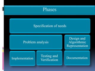
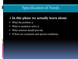
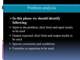
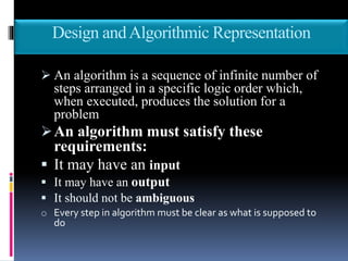
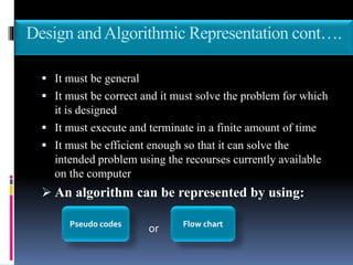
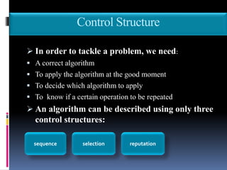

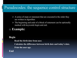
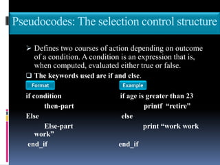
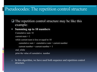

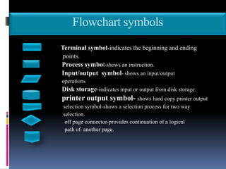
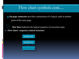
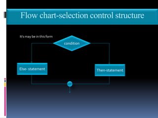
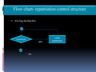
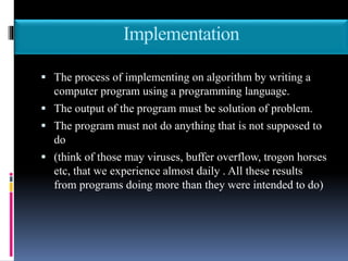
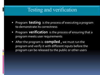

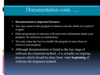


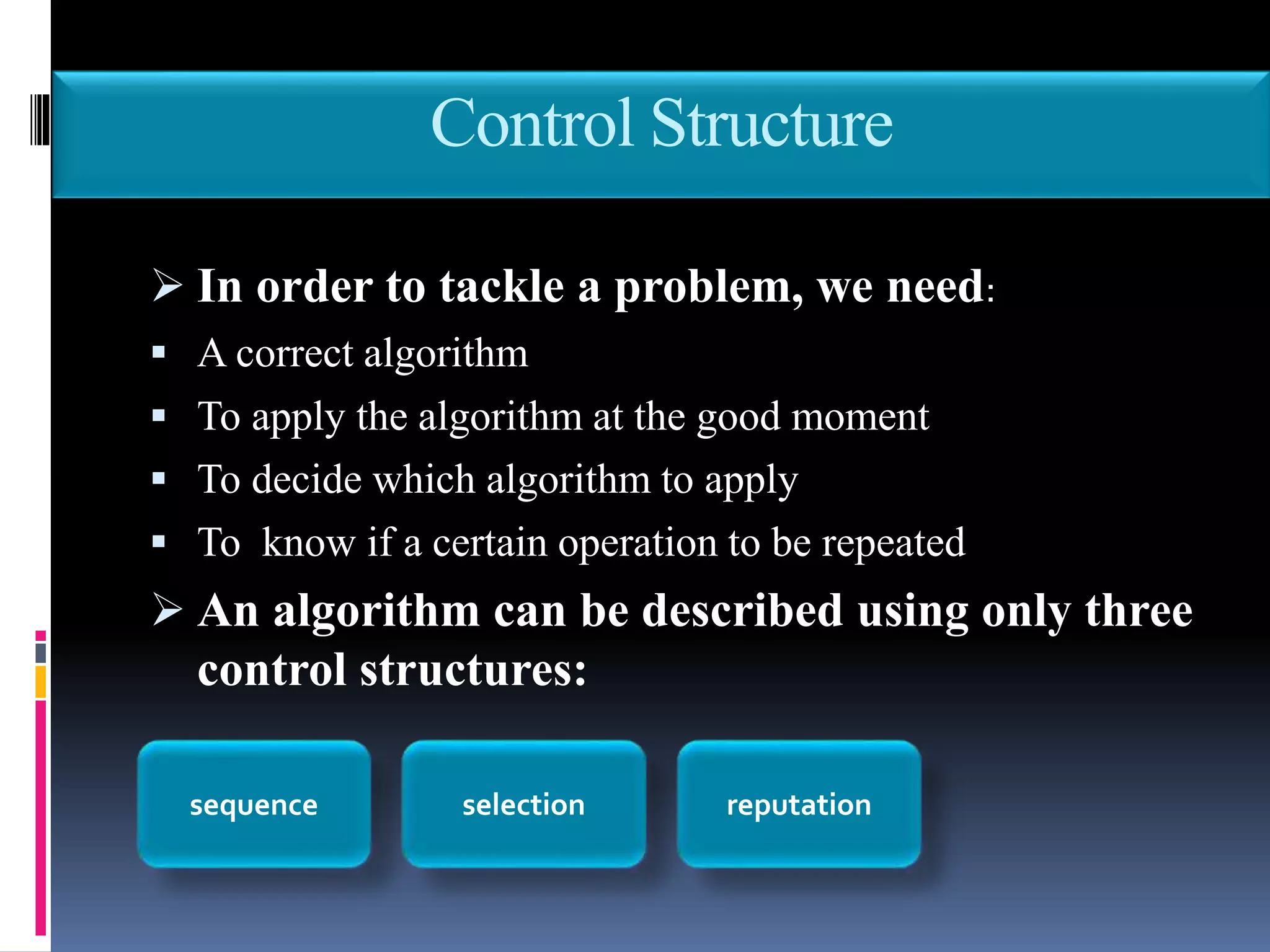

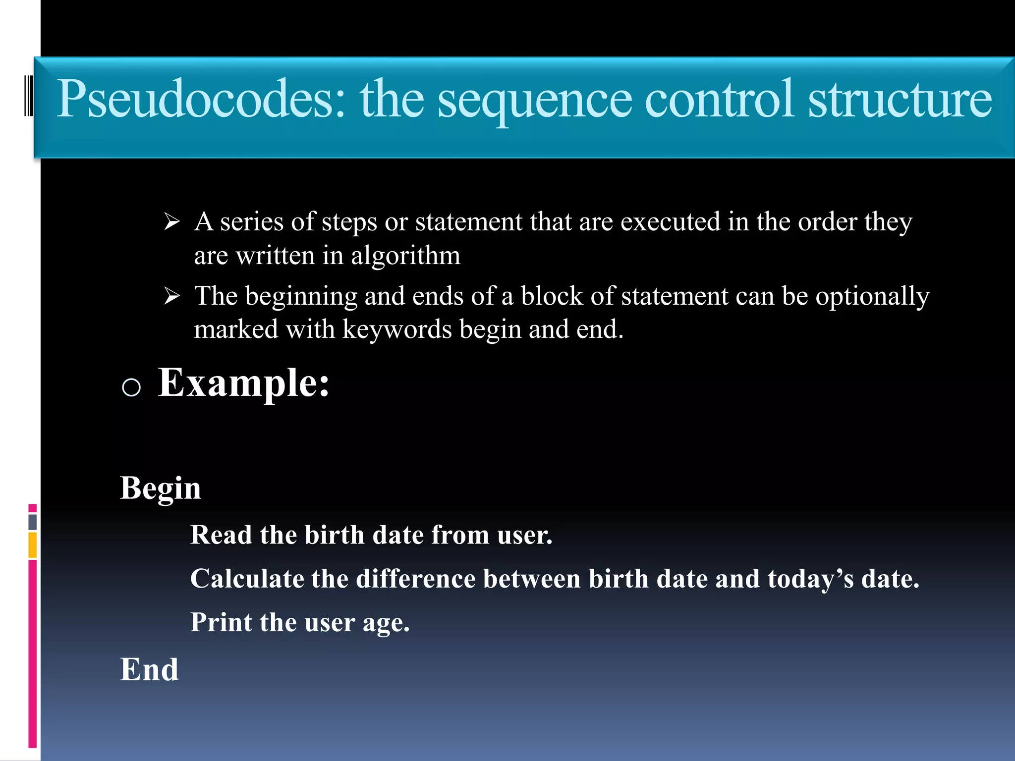
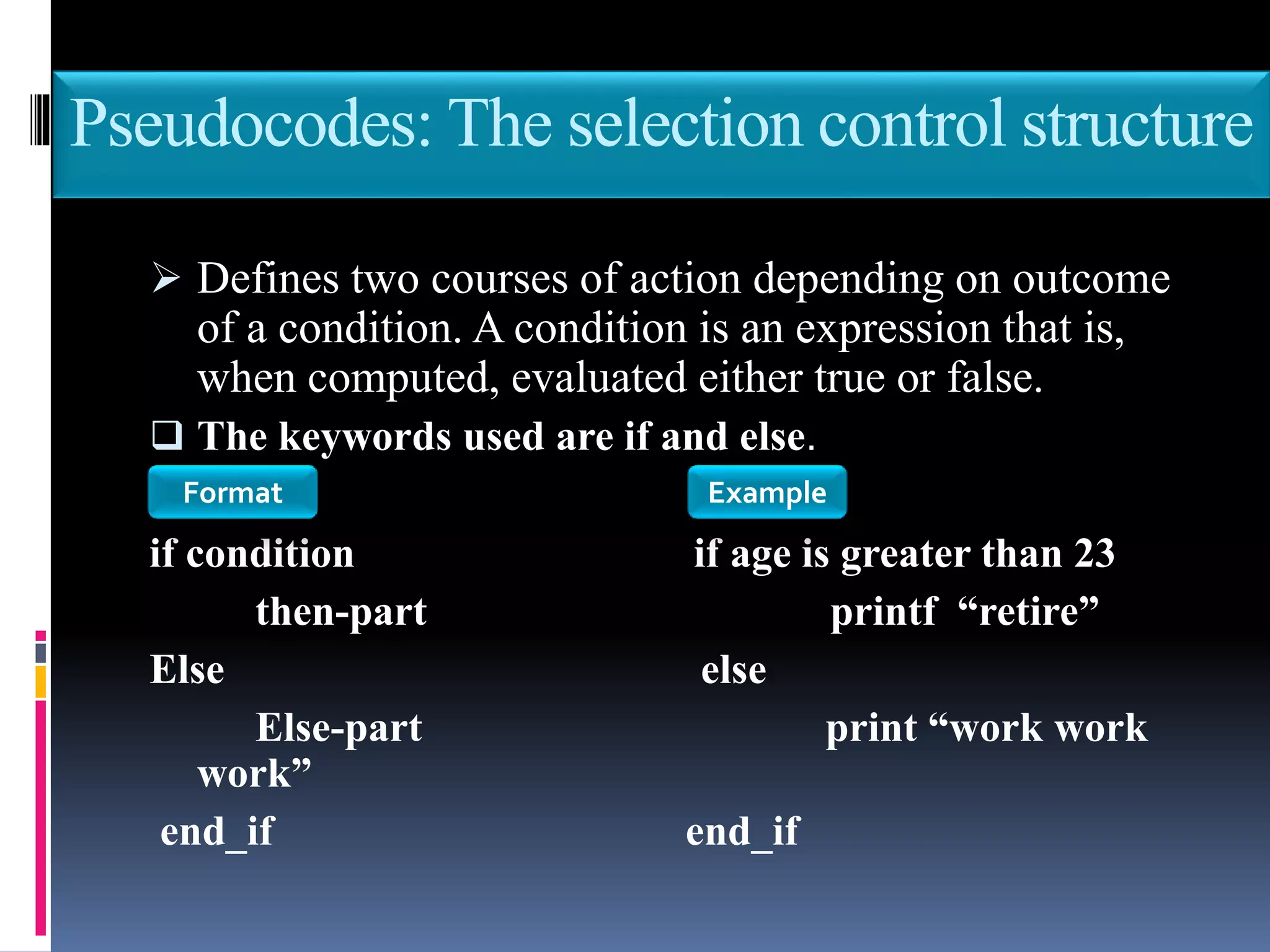
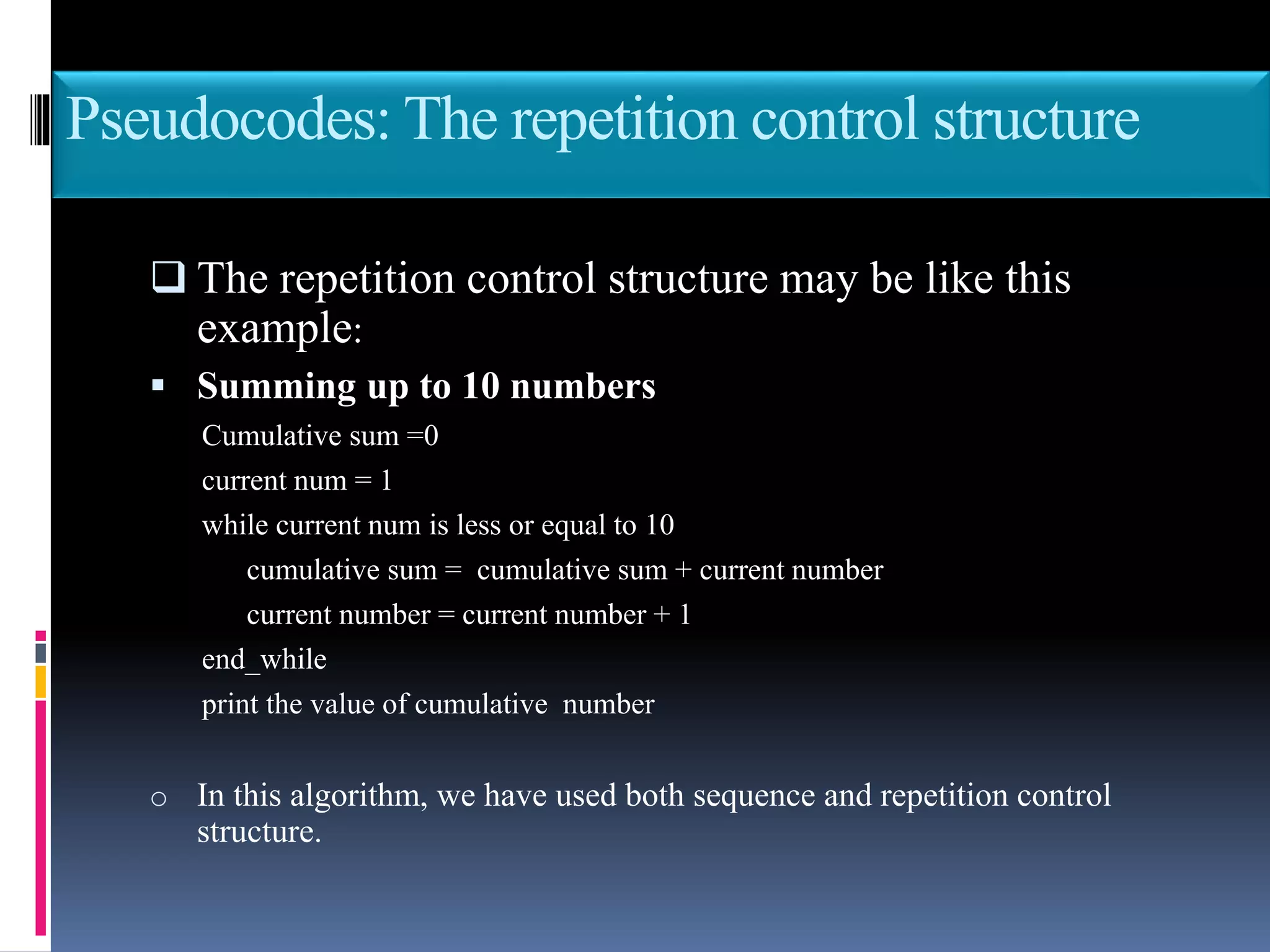


This document discusses the key phases of the Software Development Method (SDM) framework: specification of needs, problem analysis, design and algorithmic representation, implementation, testing and verification, and documentation. It provides details on each phase, including defining the problem and needed solution, identifying inputs/outputs, designing algorithms using pseudocode and flowcharts, implementing the program, testing it, and documenting the process. Pseudocode and flowcharts are presented as ways to formally represent algorithms using basic structures like sequence, selection, and repetition. The document emphasizes that documentation should be an ongoing process throughout the entire software development lifecycle.


