The document outlines various aspects of software engineering, including the software life cycle models, project management, requirement analysis, design, coding, testing, and maintenance. It describes different types of software, such as system, application, and embedded software, and emphasizes the differences between software and hardware. Additionally, it details the steps involved in the software development life cycle (SDLC) and discusses the advantages and limitations of various SDLC models, including the classical waterfall model and iterative waterfall model.
Introduction to Software Lifecycle Management, and overview chapters covering key aspects.
Definition and characteristics of software, types of software, lifecycle models including Waterfall and SDLC. Provides a comprehensive overview of the software development lifecycle (SDLC) and its major phases.
Describes different testing models, including testing strategies, prototype testing, and iteration in software development.
Discussions on software maintenance, the software crisis, reliability, and quality management principles.
Introduction to software project management principles, project staffing, management responsibilities.
Metrics for assessing software projects, including cost estimation techniques and productivity measures.
Discusses various software engineering processes, project management tools, and metrics for software quality.
Focuses on software maintenance strategies, challenges, and the importance of documentation.
Explains the role of CASE tools in software development lifecycle and their benefits.
Examines software reliability metrics, quality assurance, and implications on software products.
Quality assurance methodologies, testing objectives, and the significance of effective testing strategies.
Various testing methodologies including black-box, white-box, regression, and integration testing.
Discusses design of specific testing cases, the importance of paths and coverage in testing.
Focuses on design approaches including object-oriented design principles and software patterns.
Utilization of UML for modeling software structure, behavior, and design elements.
In-depth exploration of various software testing strategies, including unit and integration testing.
Focuses on software maintenance strategies, best practices for reuse and the evolution of models.
Overview of ISO 9000 standards, quality assurance frameworks and importance for software development.
Discusses reliability modeling, reliability metrics, and strategies for software reliability management.
Explains software configuration management and its impact on software product development.
Conclusion on key software engineering considerations, including reliability, maintenance, and project management.
1
SL.NO CHAPTER NAMEPAGE
NO.
1 SOFTWARE LIFE CYCLE MODEL 2-31
2 SOFTWARE PROJECT MANAGEMENT 32-85
3 REQUIREMENT ANALYSIS AND
SPECIFICATION
86-111
4 SOFTWARE DESIGN AND FUNCTION
ORIENTED SOFTWARE DESIGN
112-128
5 DESIGN ENGINEERING, ANALYSIS
MODEL AND ARCHITECTURAL DESIGN
129-173
6 CODING AND TESTING, SOFTWARE
TESTING STRATEGIES AND
TECHNIQUEES
174-209
7 COMPUTER AIDED SOFTWARE
ENGINEERING (CASE)
210-217
8 SOFTWARE MAINTENANCE AND
SOFTWARE REUSE
218-230
9 SOFTWARE RELIABILITY AND QUALITY
MANAGEMENT
231-245
3.
2
Software Life CycleModel
Program:
Programs are developed by individual for their personal use. They are small in
size and have limited functionality. Author of a program use and maintain his
program. These don‟t have good user interface and lack of proper documentation.
Software:
Software is a set of instructions which when executed on a computer accepts the
input and precedes it to produce the output as per the requirement of the user. It is
also accompanied by the user manual so as to understand the features and working
of the software
Software is a set of instructions, that when executed provide desired features,
function and performance; data structures that enable the programs to adequately
manipulate information and documents describe the operation and use of the
program.
Software product has multiple users and have good user interface. It has proper
user manual and good documentation support.
Characteristics of software over hardware:
Software is a logical thing rather than a physical element. Both are produced by
human being to get better quality output.
Software is engineered or developed where as hardware is produced.
1. It is not manufactured in classical sense. Similarly, exist between software
development and hardware manufacturing.
2. The 2 activities are fundamentally different.
3. In both, 5 qualities are achieved through good design. But the manufacturing
phase for hardware can introduce quality problem.
4.
3
Software does notwear out.
1. Hardware exhibits relatively high failure rate early in its life. Defects are
then corrected and failure rate drop to the steady state level for some period
of time.
2. As time passes, the failure rate rise again as hardware component suffers
from the environmental changes.
It indicates that hardware exhibits relatively high failure rates early in its life
(these failures defects). Defects are then corrected and failure rate drops to a steady
state-level for some period of time.
Its time passes failure rate rises again as hardware components suffer from so
many environmental maladies and starts to wear out. Software components do not
prone to environmental changes and the errors are corrected and then the quality
either increases to keep the idealized curve steady.
Types of Software:
There are 7 types of software present. Those are:
1. System Software: collection of program written to provide service to other
program. E.g.: compiler, editor and file management utilities. It provides
interaction with the computer hardware.
2. Application Software: consists of standalone program that solve a specific
business need. E.g.: MS-Word, C, Java etc.
Failure
Time
(Hardware failure)
Failure
Time
(Failure curve of Software)
Actual
curve
Increased
failure due
to side
effect
5.
4
3. Engineering/Scientific Software:computer aided design and other
interactive application have begun to take on real time and even system
software characteristics.
4. Embedded system: It resides within a product/system and it is used to
implement and control features and functions for the end-user and for the
system itself. E.g.: keypad control for a microwave oven, digital function in
an automobile like fuel control, dash board display and breaking system.
5. Product line Software: Design to provide a specific capability for used by
many different customers. E.g.: inventory control product, computer
graphics, multimedia, entertainment, database management.
6. Web Application Software: e.g.: E-commerce
7. Artificial Intelligence: It is used for robotics.
Software Engineering:
Software Engineering is defined as the application of a systematic, disciplined,
quantifiable approach to the development, operation and maintenance of software
i.e.: application of engineering to software.
According Pflecger 87, Software Engineering is a strategy for producing
Quality software.
According to Fritz-Bawer, Software Engineering is the establishment and use of
sound engineering principles in order to obtain economically software that is
reliable and works efficiently on real machines.
Software Engineering: A Layer Technology:
1. Any engineering approach must bases on an organizational commitment to
quality.
2. Foundation for software engineering process hold the technology layer
together and enables rational and timely development of computer
established for effective delivery of software engineering technology.
3. Methods provide the technical “how to” for building software. It include
communication, requirement analysis, design, program construction, testing
and support.
6.
5
4. Tools provideautomated and semi-automated support for the process and
method.
Features of Software Engineering:
1. Improved quality
2. Improved requirement specification
3. Better use of tools and techniques
4. Less defects in final products
5. Better maintenance of delivered software
6. Well defined processes
7. Improved productivity
8. Improved reliability
Software Life Cycle Model:
A software life cycle or software process is a series of identifiable stages that a
software product undergoes during its life time. It is a descriptive and
diagrammatic model of a software life cycle.
It identifies all activities required to develop and maintain a software product
and establishes a precedence ordering among the different activities. It encourages
development of software in a systematic and discipline manner. It helps, control
and systematically organizes various activities.
Software Development Life Cycle (SDLC):
Starting from the beginning of a software development work with
conceptualization of software being developed and ends after system is discarded
after its usage is denoted by software development life cycle (SDLC).
A quality focus
Process
Method
s
Tools
7.
6
A system studyis a step-by-step process used to identify and then to develop the
software, needed to control the processing of specific applications. This
development is done through 6 steps.
1. Requirement Analysis
2. System Analysis
3. System Design
4. Program Implementation
5. Testing
6. Software Maintenance
The SDLC is categorized in 3 approaches. Those are:
1. To understand the business problem and opportunity
2. Development of information and system solution
3. Implementation of information system solution.
Requirement Analysis Product: Feasibility Study
System Analysis Product: System‟s Requirement
System Designing Product: Systems
Specification
Program Implementation Product: Operational
System
Maintenance Product: Improved System
Approach (i)
Approach (iii)
Approach (ii) Testing
Cycle
Maintenance Cycle
8.
7
Types of SoftwareLife Cycle Model:
1. Classical Waterfall Model
2. Iterative Waterfall Model
3. Prototyping Model
4. Evolutionary Model
5. Spiral Model
6. Build-Fix Model
7. V-Model
8. Component based development Model
9. Structural Model
10.Rapid Application Development (RAD) Model
Classical Waterfall Model:
This model divides the life cycle of a software development process into
phases. This life cycle model is named as waterfall model because its
diagrammatic representation resembles a cascade of waterfall.
The different phases are described below.
Requirement Analysis and Specification
Design
Feasibility Study
Integration and System Testing
Maintenance
Coding and Unit Testing
9.
8
Feasibility Study:
The aimof this is to determine whether developing the product is financially
and technically feasible. It involves analysis of problem and collection of data
which would be input to the system, the processing required to carry out in this
data.
The output data required to be produced by the system as well as study of
various constraints on the behavior of the system.
The collected data are analyzed to arrive at the following:
1. Abstract definition problem
2. Formulation of different5 solution strategy
3. Examination of alternative solution and their benefit, indicating resource
required development, cost and time in respect of each of the alternative
solution
4. A cost and benefit analysis is performed to determine which solution is best
1) Economic Feasibility Study:
i. In this type of feasibility study the focus is on determining the project
costs and benefits.
ii. Costs and benefits both can be tangible or intangible.
iii. Economic feasibility uses the concept of time-value money (TVM)
which compares the present cash outlays to future expected returns.
2) Technical Feasibility Study:
i. It implies all technical things which supports in making the
organizations.
ii. It focuses on organization‟s ability to construct the proposed system in
terms of hardware, software, operating environment, project size,
complexity, and organization‟s experience in handling similar type of
work and risk analysis.
iii. As well as we have to find out the answer of some more questions
while studying technical feasibility.
10.
9
a. Does thecurrent technology exist to do what is suggested?
b. Does the proposed equipment's have the technical capability to
hold the data required to use the new system?
c. Will the proposed system provided adequate responses to
enquiries, regardless the number of users? Can the system be
expanded if developed?
d. Are there technical guarantees of accuracy, reliability, ease of
access and data security?
3) Operational Feasibility Study:
i. It deals with accessing the degree to which a proposed system solves
business problems. That is: it refers to the compatibility of a new
system with employee activities and organizational procedures.
4) Organizational Feasibility Study:
i. It says how well a proposed system supports the strategic plan of the
organization and its environmental existence.
Requirement Analysis and Specification:
This phase focuses on understanding the problem domain and representing the
requirements in a term which are understandable by all the stake holders of the
project. That is: analyst, user, programmer, tester etc.
The output of this stage is a document called Requirement Specification
Document (RSD) or Business Requirement Specification (BRS) or Users
Requirement Specification (URS).
It is used to understand the exact requirement of the customer and document
them properly. It consists of 2 different activities.
1. Requirement Analysis
2. Requirement Specification
The goal of requirement analysis is to collect and analyze all related data and
information with a view to understand the customer requirement.
11.
10
Requirement analysis startswith the collection of all relevant data regarding the
product from the user through interviews and discussion. During requirement
specification, the requirement are properly organized and documented in a
software requirement specification (SRS) document.
The SRS document addresses the functional requirement, non-functional
requirement and special requirement on the maintenance and development of the
software. SRS document serve as the construct between development team and
customer.
System Design:
The requirement specifications are transformed into a structure. That is: suitable
for implementation in some programming language.
This phase carry out the translation of the requirement specification document
(RSD) done in the previous phase which depicts the overall modular structure of
the program and the interaction between the modules.
The types of system design are:
1. Physical design,
2. Logical design and
3. User Interface Design.
The two distinct design approach are been followed in different industries. That
is:
1. Traditional design approach
2. Object oriented design
1) Traditional Design Approach:
It requires two different activities to be performed. That is:
1. Structured analysis of requirement specification
2. Structured analysis is transferred into software design
12.
11
Structured analysis involvedpreparing a detailed analysis of different
function to be carried out by the system and identification of dataflow
among different function.
After structured analysis, architectural or high level design and detailed
or low level design are carried out.
2) Object Oriented Design:
Here various objects occur in the problem domain and solution domain,
are first identified and then the different kind of relationship that exists
among these objects are identified.
Coding and Unit Testing:
The purpose of this is to translate the software design into source code. Here
each component of the design is implemented as a program module and each of
these program modules is unit tested, debug and documented.
The purpose of unit testing is to determine the correct working of individual
module.
Integration and System Testing:
Here the different modules are integrated. Integration is carried out through a
number of steps.
System testing usually consists of 3 different kinds of testing activities. That is
1. α – testing: It is a system testing performed by development team
2. β – testing: It is performed by friendly at customers.
3. Acceptance testing: it is performed by the customer himself.
System Testing is normally carried out in a planned manner according to the
system test plan document.
13.
12
Implementation, Deployment andMaintenance:
Implementing the low level design part for algorithms into programming
language coding, databases is done in this phase. Deployment makes the system
operational through installation of system and also focuses on training of users.
Maintenance phase resolves the software errors, failures etc. enhances the
requirements if required and modifies the functionality to meet the customer
demands.
It consists of 3 kinds of activities.
1. Correcting errors that were not discovered during product development
phase, this is known as “corrective maintenance”.
2. Improving the implementation and enhancing the functionality of the
system according to customer requirements. This is called “perfective
maintenance”.
3. Porting of the software to a new environment. This is called “adaptive
maintenance”
Advantages of Classical Waterfall Model:
1. It is a linear, segmental model.
2. It is systematic, sequential and simple.
3. It has proper documentation.
4. Easy to understand.
5. Each phase has well-defined input and output.
6. Each stage has well-defined deliverables or milestones.
7. Helps the project manager in proper planning of the project.
Limitation:
1. It assumes that no defect is introduced during any of the phases of the life
cycle, but in practical development environment, defect gets introduced in
almost every phase of life cycle.
14.
13
2. These defectsusually get detected much later in the life cycle. Due to this
reason, iterative waterfall model is introduced. Here we can go in backward
direction.
Disadvantages:
1. It is difficult to determine or define all requirements at the beginning of the
project.
2. This model is suitable for any changes.
3. A working version of the system is not seen until late in the project life.
4. It does not scale up well to large project.
5. In involves heavy documentation. We can‟t go in backward direction while
SDLC perform.
6. There is no sample model for clearly in realization the customer need.
7. There is no risk analysis.
8. If there is any mistake or error in any phase, then we can‟t make good
software.
9. It is a document driven process that require formal document at the end of
each phase.
10.It does not support iteration.
11.It is sequential in nature. i.e.: one cannot start with a stage till proceeding
stage is completed.
12.Users have little interactions with the projection.
13.Difficulty in accommodating changes in the product after the development
process starts.
14.Amount of documentation produced is very high. No support for delivery of
system is pieces.
15.
14
Iterative Waterfall Model:
Itis the modified waterfall model that supports the iteration procedures and
better than the previous one.
Phase Containment of Errors: The Principle of detecting error as close to
its point of introduction as possible is known as “phase containment of errors.”
In any practical development environment, several iterations through the
waterfall stages are normally necessary to develop the final product. In spite of
this, the final documents for the product should be written as if the product was
developed using a pure classical waterfall model.
Even though a basic understanding of the waterfall model is necessary to be
able to appreciate the other development processes, the waterfall model suffers
from many shortfalls.
Requirement
Analysis and
Specification
Design
Feasibility Study
Integration and
System Testing
Maintenance
Coding and
Unit Testing
16.
15
Shortcomings of IterativeWaterfall Model:
1. The waterfall model can‟t satisfactorily handle the different types of risks
that a real life software project is subjected to.
2. To achieve better efficiency and higher productivity most real life projects
can‟t follow the rigid phase sequence imposed by waterfall model.
3. A rigid adherence to waterfall model creates “blocking states” in the system.
Prototyping Model:
A prototype is a partially developed product. It is defined as prototyping as a
process of developing working replica of a system. Prototyping is used for
developing a mock-up of product and is used for obtaining user feedback in order
to refine it further.
In this process model, system is partially implemented before or during analysis
phase thus giving the end users an opportunity to see the product early in the life
cycle. The process starts by interviewing the users and developing the incomplete
high level paper model. This document is used to build the initial prototype
supporting only the basic functionality as desired by the user.
The prototype is then demonstrated to the user for feedback and after that the
user pinpoints the problems, prototype is further redefined to eliminate the
problems. This process continues till the user approves the rapid prototype and
finds the working model to be satisfactory.
Customer Feedback Develop/Refine Prototype
Testing of Prototype
by customer
Results into Used for
is used to
(Prototyping Concept)
17.
16
The prototype modelsuggests that, before the development of actual software, a
working prototype of the system should be built. A prototype is a toy
implementation of a system usually exhibiting limited functional capabilities, low
reliability and inefficient performance. There are several reasons for developing a
prototype.
1. To illustrate the input data format message, report and the interactive
dialogues to the customer.
2. It helps to critically examine the technical issues associated with the product
development.
This model starts with an initial requirement gathering phase. A quick design is
carried out and the prototype model is build using shortcut. It might involve using
inefficient inaccurate dummy function.
Requirement Gathering
Customer Evaluation of
the Prototypes
Test
Design
Implement
Acceptance of customer
Maintain
Quick Design
Build PrototypeRefine Requirement
Customer
Suggestion
18.
17
The developed prototypeis submitted to the customer for his evaluation. Based
on user feedback the requirements are refined. This cycle continues until the user
approves the prototype. The actual system is then developed using classical
waterfall model.
Approaches of Prototyping:
1) Rapid Throwaway Prototyping:
This approach is used for developing the systems or part of the system.
The quick and dirty prototypes are built, verified with the customers and
thrown away. This process continues till a satisfactory prototype is built. At
this stage, now the full scale development of the product begins.
2) Evolutionary Prototyping:
This approach is used when there is some understanding of the
requirements. The prototype thus built are not thrown away but evolved with
time.
Evolutionary Prototype
Maintain
Deliver
Test the final Product
Refine Prototype
Discard Prototype
Develop Final SRS
Implement
Design
Test
Deliver & Maintain
Rapid Throwaway
Prototyping
19.
18
Advantages:
1. A partialproduct is built in initial stages. Therefore customer gets a chance
to see the product early in the life cycle.
2. New requirements can be easily accommodated.
3. Scope for refinement.
4. Flexibility in design and development.
5. Suitable for large system for which there is no manual process to define the
requirement.
6. User service determination.
7. Quality of software is good.
Limitation and Disadvantages:
1. It was difficult to find all the requirements of the software initially.
2. It was very difficult to predict how the system will be after development.
3. Developers in a hurry to build prototypes may end up with sub-optimal
solutions.
4. If not managed properly, the iterative process of prototype demonstration
and refinement may continue for a long duration.
5. Poor documentation.
Evolutionary Model:
This model is called as “successive version model” or “incremental model”.
Here A, B, C is the modules of a software product that are incrementally
developed are delivered. In this model, the software is first broken down into
several modules or functional units, which can be incrementally constructed and
delivered.
A A
B
A
B
C
Evolutionary
Development of a
software product
20.
19
The development teamfirst develops the core modules of the system. This
initial product skeleton is refined into increasing levels of capability by adding new
functionalities in successive versions.
Each evolutionary version may be developed by using on iterative waterfall
model of development. Each successive version of the product is fully functioning
software capable of performing more useful work than the previous versions
Advantages:
1. The user gets a chance to experiment with a partially development software,
much before the complete version of the system is release. So it helps to
accurately elicit user requirements during the delivery of the complete
software are minimized.
2. The core modules get tested thoroughly. So reducing the chances of errors in
the core modules of the final product.
3. It oviates the need to commit large resources in one go for development of
the system.
Rough Requirements Specifications
Develop the core part using an iterative
waterfall model
Develop the next identified features
using an iterative waterfall model
Maintenance
Identify the core and other parts to be
developed incrementally
All features complete
21.
20
Disadvantages:
1. It isdifficult to divide the problem into several functional units which can be
incrementally implemented and delivered.
Spiral Model:
This model was proposed by Boehm in 1988. This model focuses on
minimizing the risk through the use of prototype, as it is a view of a waterfall
model with each stage preceded by a risk analysis stage.
This model is known as “meta model”. It determine objective identify
alternative. It evaluate alternative identify and resolve risk. Develop the next level
of product i.e.: Customer evaluation of the prototype. This model is also termed as
process model generator.
The radial co-ordinates in the diagram represent the total costs incurred till date.
Each loop of the spiral represents one phase of the development. The software
development for this model is carried out in 4 main phases or 4 quadrants, each
with a specific purpose.
1. The 1st
quadrant identifies the objective of the product and the alternative
solution possible.
2. In 2nd
quadrant, the alternative solution is evaluated and potential project
risks are identified and dealt with by developing an appropriate prototype. A
project risk is essentially any adverse circumstances that might hamper
successful completion of software project. So the spiral model provides
direct support for coping with the project risk.
3. The 3rd
quadrant consists of developing and verifying the next level of
product. It consisting of activities such as design, coding and testing.
4. The 4th
quadrant consists of reviewing the results of the stages traversed so
far with the customer and planning the next iteration around the spiral.
With each iteration around the spiral, a more complete version of the software
gets built progressively.
22.
21
The 4th
quadrant ismeant for customer product evaluation before the
completion of the 1st
spiral cycle and the requirement are further refined and so is
the product.
After several iterations along the spiral all risks are resolved and the software is
ready for development. At this point, a waterfall model of the development is
adapted. If at some stage, risks cannot be resolved, the project is terminated.
Advantages:
1. It is a risk driven model and very flexible.
2. Less documentation is needed and it was prototyping.
3. Tries to resolve all possible risks involved in the project starting with the
highest risk.
4. End users get a chance to see the product early in life cycle.
5. With each phase as product is refined after customer feedback, output
becomes of good quality.
Planning next phase
Customer
Requirement
Risk Analysis
Customer Evaluation
Engineering the
product i.e.:
design, coding
and testing
1
2
4 3
Start
23.
22
Disadvantages:
1. No riskstandard for software development.
2. No particular beginning or end of particular phase.
3. It requires expertise in risk management and excellent management skills.
4. Not suitable for small projects as the cost for risk analysis may exceed the
actual project cost.
5. It is very complex.
6. Time consuming.
Build-Fix Model:
Techniques used in the initial years of software development resulted into the
term Build-Fix Model. Using this model, the product was not constructed using
proper specification and design, resulted in a number of project failures for large
projects.
Advantages:
1. It is useful for very small projects.
Disadvantages:
1. It is not at all suitable for large projects.
2. As specifications are not defined, result product is full of errors.
3. Reworking of product results into increases cost.
4. Maintenance of product is extremely difficult.
Build product
Fix and Revise
the product
24.
23
V-Model:
This model wasdeveloped to relate the analysis and design activities with the
testing activities and this focuses on verification and validation activities of the
product.
The dotted line (----) indicates that the corresponding phase must be carried out
in parallel. As in waterfall model, V-model should be used, when all the
requirements of the project are available in the beginning of the project.
Advantages:
1. Simple and easy to use.
2. Focuses on testing of all intermediate products, not only in the final
software.
3. Plans for verification and validation activities early in the life cycle there by
enhancing the probability of building an error free and good quality product.
Business case and
work strategy
System
Design
Detailed
design
Integration
Testing
Unit
Testing
Product
Verification
Acceptance
Testing
Requirement
Analysis
Coding
Analysis Phase Verification
Phase
25.
24
Disadvantages:
1. Does notsupport iteration of phases and change in requirements throughout
the life cycle.
2. Does not take into account risk analysis.
Component-Based Development Model:
A component is a non-trivial, independent and replaceable part of a system that
fulfills a clear function in the context a well-defined architecture.
Component-based software engineering (CBSE) is a process that emphasizes
the design and construction of computer based systems using reusable software
components. In CBSE, collecting the requirements for the system the team
examines the requirements in more details rather than moving directly to the
detailed design and construction.
The following questions need to be placed:
i. Are commercial off-the-self (COTS) components available to implement the
requirements?
ii. Are internally developed reusable components available to implement the
requirement?
iii. Are the interfaces for available components compatible within the
architecture of the system to be built?
The term attempts to modify or delete the system requirements that cannot be
implemented with COTS, if possible else these new to develop different software
engineering methods to achieve the requirements.
1) Software Components:
A unit of composition with contractually specified and explicit context
dependencies only.
2) Run-time Software Component:
A dynamic bindable package of one or more programs as a unit and
accessed through documented interfaces that can be discovered in run time.
26.
25
3) Domain Engineering:
Itis to find out the behavior and functional part of each component. The
component composition is based on:
a. Data exchange model
b. Automation tools
c. Structure storage( i.e.: videos graphics, animation, text)
Notes:
1. A structural point is basically a construction having limited instances i.e.: the
size of class hierarchy should be small.
2. Rule governing the structural point should be easy and small.
3. Structural point should try to minimize or avoid the complexities that arise
in the particular model
Domain Analysis
S/W Architecture
Development
Reusable Component
Development
Domain Engineering
Structure ModelDomain Model
Component
update
Application
Software
Analysis
Architectural
Design
Component Qualification
Component based Development
Testing
Component
Engineering
Component Adaptation
Component
Composition
27.
26
Rapid Application Development(RAD) Model:
This RAD model was proposed in IBM in 1980‟s. The important feature of
RAD model is increased involvement of the user or customer at all stages of life
cycle through the use of powerful development tools.
Rapid application development is an incremental software process model that
emphasizes a short development cycle. It is a high speed adaptation of the waterfall
model, in which rapid development is achieved by using a component based
construction approach.
Like other process models, the RAD approach maps into the generic framework
activities presented earlier. Communication works to understand the business
problem and the information characteristics that the software must accommodate.
Planning is essential because multiple software teams work in parallel on different
system function. Modeling encompasses 3 major phases.
1. Business modeling
2. Data modeling
3. Process modeling
The established design representation that serve as the basis for RAD‟s
construction activity.
Construction emphasis the use of pre-existing software components and the
application of automatic code generation. Finally deployment establishes a basis
for subsequent iterations.
If the requirements of the software to be developed can be modularized in such
a way, that each of them can be completed by different teams in a fixed time, then
the software is a candidate for RAD.
The independent modules can be integrated to build the final product. The
important feature of this model is quick turnaround time from requirement analysis
to the final delivered system. The time frame for each delivery is normally 60-90
days called the Time Box.
28.
27
Advantages:
1. Leads tocustomer satisfaction as this involvement in all stages.
2. Use of powerful development tools resulting reduced development cycle
time.
3. Feedback from the customer is available at the initial stages.
4. Results into reduced costs as less developers are required.
Disadvantages:
1. Hiring of skilled professional is required for the use of efficient tools.
2. Absence of reusable components can lead to failure of the project.
3. For large, but scalable projects, RAD requires sufficient human resources to
create the right number of RAD items.
4. If developers and customers are not committed to the rapid fire activities to
complete system in time frame, RAD projects will fail.
5. If a system can‟t be properly modularized building the components for RAD
will be problematic.
6. If high performance is an issue and performance is to be achieved through
turning the interfaces to system components the RAD approach may not
work.
7. RAD may not be appropriate when technical risks are high.
Integrates all the
modules
Elicit Requirements
Develop
Module 1
Test the final product and deliver
Modularize Requirements
Analyze
Develop
Module 2
Develop
Module N
Test
Code
Design
29.
28
Structural Model:
It consistsof small number of structural elements manifesting clear pattern of
interactions.
Emergence of Software Engineering:
1) Early Computer Programming:
Early computer were very slow and too elementary as composed to
today‟s standard. Every simple processing task takes considerable
computation time. Programs are written in assembly language. Every
programmer developed his own individualistic style of writing.
2) High Level Language Programming:
It helps programmers to write large programs. This reduced software
development efforts. Programs were limited to sizes of around a few
thousands of line of source code.
3) Control Flow Based Design:
As the size and complexity of program increased programming style
proved to be insufficient. Programmers found it difficult, not only to write
cost effective and correct programs but also to understand and maintain
programs written by other programmer.
To overcome this problem, programmers paid attention to the design of
the programs control structure. A control structure indicates the sequence in
which the programs instructions are executed. Here GOTO statements are
used.
4) Structured Programming:
A program is called structured, when it uses only the sequence and
iteration type of constant.
30.
29
5) Data StructuredOriented Design:
The design of data structure of a program is more important that the
design of its control structure. Design techniques based on this principle are
called data structured oriented design technique.
6) Dataflow Oriented Design:
This technique advocate that the major data items handled by a system
must be first identified and then the processing required on these data items
to produce the required output should be determined. The dataflow
technique identified the different processing stations in a system and the
items that flow between the different processing stations.
7) Object Oriented Design:
Here objects occurring in a problem are first identified and then the
relationship among objects like composition, reference and inheritance are
determined.
Advantages of Software Development:
1. The main emphasis has shifted from error correction to error prevention. It
has been realized that it is much more cost effective to prevent errors than to
correct them as and when they are detected.
2. Coding is regarded as only a small part of the different activities undertaken
for program development. There are several development activities like
design and testing which require more effort than testing.
3. Lots of effort and attention is paid to requirement specification.
4. Periodic reviews are carried out during all stages of the development
process.
5. Today software testing has become more systematic and for which standard
testing techniques are available.
6. There is better visibility of design and code. By visibility we mean the
production of good quality, consistent and standard documents. Because of
good documentation, fault diagnosis and maintenance are for smoother.
31.
30
7. Several techniquesand tools for tasks life configuration management, cost
estimation, scheduling and task allocation have been developed to make
software project management more effective.
Software Crisis:
During the development phase of software many problems occur. This is known
as “Software Crisis”.
Problems:
1. Scheduling and cost estimation are often inaccurate.
2. The productivity of software people has not keep pace with the demand for
their services.
3. The quality of software is sometimes less than adequate.
4. With no solid indication of productivity, we cannot accurately evaluate the
efficiency of tools, methods and standard.
5. Communication between customer and developer is poor. Software
maintenance task require the majority of the software rupees.
Causes of Software Crisis:
1. Quality of software is not good, because most of the developer use the
historical data to develop the software.
2. If there is a delay in any process or stages the scheduling does not match
with actual timing.
3. Communication between managers, customer software developer support
staff can breakdown because the special characteristics of software and the
problem associated with its development.
4. The software people responsible for tapping that potential often changes,
when it is discussed and resists the change when it is introduced.
Software Crisis in Programmer‟s point view:
1. Problem of compatibility.
2. Problem of portability.
3. Problem in documentation.
32.
31
4. Problem inpiracy of software.
5. Problem in co-ordination of work different people.
6. Problem of maintenance in proper manner.
Software Crisis in User‟s point view:
1. Software cost is very high.
2. Customers are moody.
3. Hardware goes very down.
4. Lack of specialization in development.
5. Problem of different version of software.
6. Problem of views and vugs.
-: The End :-
33.
32
Software Project Management
SoftwareProject Management:
The main aim of software project management is to enable a group of software
engineer to work efficiently towards successful completion of project.
Project management can be defined as the management of procedures,
techniques, resources and know-how technology etc., required for successful
management of the project.
Project management is the application of knowledge, stalls, tools and
techniques to project activities to meet the project managements. If the final
product of the project is the software, then it is known as software project
management.
Job Responsibility of a software project management:
1. Building a team moral.
2. Estimating cost
3. Scheduling
4. Project staffing
5. Software process tailoring
6. Project monitoring and control
7. Software configuration management
8. Risk management
9. Interfacing with the client.
10.Report writing and presentation.
Skills Necessary for software project management:
1. Good Qualitative Judgment.
2. Decision making capabilities
34.
33
3. A goodgrasp of the latest software project management techniques such as
cost estimation, risk management, configuration management. Project
manager needs good communication skills and ability to get work done.
4. Tracking and controlling the progress of the project, customer interaction,
managerial presentations and team building are largely acquired through
experience.
Steps for Project Management:
Basically the steps required are the 4Ps. Those are:
1. People
2. Product
3. Process
4. Project
1) People:
People must be organized to perform software work effectively.
Communication with the customer and other stakeholders must occur so that
product scope and requirements are understood.
The people factor is so important that the software engineering Institutes has
developed a People Management Capability Maturity Model (PM-CMM) to
enhance the readiness of software organization‟s to undertake increasingly
complex applications by helping to attract, grow, motivate, deploy and retain
the talent needed to improve their software development capability.
Where PM-CMM defines some key practice area for software people like
recruiting, selection, performance management, training, compensation, team
culture development etc.
2) Product:
Before a project can be planned, product objectives and scope should be
considered and technical and management constraints should be identified.
Without this information, it is impossible to define reasonable estimates of the
35.
34
cost, an effectiveassessment of risk, a realistic breakdown of project tasks or
manageable project schedule that provides a meaningful indication of progress.
The software developer and customer must meet to define product objectives
and scope. Objectives identify the overall goals for the product without
considering how these goals will be achieved.
Scope identifies the primary data, functions and behaviors that characterize
the product and more importantly attempts to bound these characteristics in a
quantitative manner.
3) Process:
A software process provides the framework from which a comprehensive
plan for software development can be established. A small number of
framework activities are applicable to all software projects, regardless of their
size or complexity.
4) Project:
A project can be defined as an enterprise carefully planned to achieve a
particular aim or it is a temporary endeavor undertaken to create a unique
product, service or result. The objective of any project is to build a good quality
product well within the budget and schedule.
The project must be planned by estimating effort and calendar time to
accomplish work tasks. We conduct planned and controlled software projects
for one primary reason – it is the only known way to manage complexity.
To avoid project failure, a software project manager and the software
engineers who build the product must heed a set of common warning signs,
understand the critical success factors that lead to good project management and
develop a common sense approach for planning, monitoring and controlling the
project.
36.
35
Project planning:
It consistsof essential activities. i.e.:
1. Estimating some basic attributes of the project
a. Cost: how much will it cost to develop the project
b. Duration: how long will it take to complete the development?
c. Effort: how much effort would be required?
d. The effectiveness of the subsequent planning activities is based on
the accuracy of these estimations.
2. Scheduling manpower and other resources
3. Staff organization and staffing plans
4. Risk identification, analysis and abatement planning.
5. Miscellaneous plans such as quality assurance plan, configuration
management plan etc.
The Software Project Management Plan (SPMP)
document:
After completion of project planning, project manager, document the result of
the planning phase on software project management plan (SPMP) documents. It
includes the following items.
Effort Estimation Cost Estimation
Size Estimation
Duration
Estimation
Project
Staffing
Scheduling
[Precedence ordering among planning activities]
37.
36
1. Introduction: objectives,major function, performance issue, management
and technical constraints.
2. Project Estimate: Historical data, estimation techniques and effort,
resource, cost and project duration estimates are used.
3. Schedule: work breakdown structure, task network representation, Gantt
chart Representation and PERT chart Representation.
4. Project Resources: It includes team structure and management reporting.
5. Staff Organization: It includes team structure and management reporting.
6. Risk Management Plan: It includes risk analysis, risk identification, risk
estimation and risk abatement procedures.
7. Project Tracking and Control Plan: This plans the control of project and
track the project.
8. Miscellaneous Plans: It includes process tailoring, quality assurance plan,
configuration management plan, validation and verification, system testing
plan and delivery, installation and maintenance plan.
Software Metric:
Software Metric is quantifiable measure that could be used to measure different
characteristics of the software system as software development system. It is useful
only if they are characterized effectively and validated so that their worth is
proven.
Software metrics can be used to:
1. Predict success and failure quantitatively.
2. Control quality of the software.
3. Make important and meaningful estimates.
4. Predict quantified estimates
Software quality metrics can be estimated in 3 categories:
1. Product metrics
2. Process metrics
3. Project metrics
38.
37
1) Product Metrics:
Itdescribes the effectiveness and quality that produce the software
product. It includes the following:
i. A fact require in the process.
ii. Time to produce a product.
iii. Effectiveness of a detect removal during development.
iv. Number of defects found during testing
v. Maturity of the metric
2) Process Metrics:
Process metrics are collected across all projects and over long periods of
time. Their intent is to provide a set of process indicators that lead to long-
term software process improvement.
The only rational way to improve any process is to measure specific
attributes of the process, develop a set of meaningful metrics based on these
attributes and then use the metrics to provide indicators that will lead to a
strategy for improvement. Software process metrics can provide significant
benefit as an organization works to improve its overall level of process
maturity.
3) Project Metrics:
Project metrics enable a software project manages to:
i. Access the status of an ongoing project.
ii. Track potential risks.
iii. Uncover problem areas before they go critical.
iv. Adjust work flow or tasks.
v. Evaluate the project teams‟ ability to control quality of software
work products.
Software project metrics are tactical. It describes the project
characteristics. It includes:
39.
38
i. No. ofsoftware developer
ii. Cost and structure
iii. Productivity
iv. Man power
Software Process and Project Metrics:
1. Measurement:
It is a fundamental to any engineering discipline which will provide
mechanism for objective evaluation. Software metrics refer to broad range
measurement for computer software. Measuring is done throughout the
software project to assign quality control, estimation, productivity,
assessments etc.
2. Measure:
It provides a quantitative indication of extent amount, dimension and
capacity, size of some attributes or process. A software engineering collects
measures and develops metrics so that indicators will be obtained.
3. Indicator:
It is a metric or combination of metrics that provides information about
the software process, product and project. It helps the project manager to
adjust measures for process and product.
4. Metrics:
It refers to the quantitative measure of degree to which a system or
component or process possess a given attribute.
5. Work Product:
It is a set of software metrics that provide inside into the process and
understanding of the project.
40.
39
6. Difference betweenProcess and Project:
Each individual activity is a process where as combination of all process
is the project.
7. Software Metric Ediquity (Code of conduct):
Use of commonsense and organization sensitivity when interpreting
metrics data. Provide regular feedback to the individuals and teams. Don‟t
use metrics to appraise individuals. Work with the developers as well as with
all the team members to set goal and metrics. Metrics data that indicate
problem should not be treated as a negative factor.
8. Private Metrics:
It includes defect rates by individuals, by software component and error
found during development.
9. Public Metrics:
Some process metrics are private to the software project team but public
to all team members like project level defect rates, calendar time etc.
10. Process Metric:
Process metrics are collected across all projects and over long periods of
time. Their intent is to provide a set of process indicators that lead to long-
term process improvement.
Process is the only one of a no. of controllable factors in improving
quality and organization performance.
The process triangle exists within a circle of environmental conditions
exists within a circle of environmental conditions that includes development
environment, business conditions (i.e.: deadlines business rules) and
customer characteristics. (e.g.: case of communication and collaboration).
41.
40
Project Size Estimation:
Thesize of the program is not the no. of bytes size of the executable, but it is
the indicator of the effort and times require developing a program. Estimating the
size is found to estimate the time and cost of a planned software project.
In order to estimate the size, requirement of the software must be well defined
terms of functional requirements, non-functional requirements and interfaces to be
used in the software.
There are several metrics are used to measure the problem size that are: Lines of
code (LOC), Function Point Metric (FP), Feature Point Metric, Object points and
No. of entities in ER diagram.
Lines of Code (LOC):
This is the simplest metric, because it is simple to use for estimating the size
of the software and often quoted in 1000‟s (KLOC). It measures the no. of source
instruction required to solve a problem. Estimating LOC count at the end of the
project is very simple. It‟s estimation at the beginning is very tricky.
To estimate the LOC at the beginning of the project, the project manager
divide the problem into module and each module into sub-module and so on until
the size of the different leaf level module can be predicted. By using the estimation
of the lowest level module, the project manager arrives at the total size estimation.
Process
People
Product
Technology
Development
Business
Conditions
Customer
Characteristic
s
42.
41
Physical LOC isthe physical lines of code in the program where as Logical
LOC is the logical lines of code. (i.e.: not the syntax line except the logics).
E.g.: for(i = 0; i < 5; i++)
{
printf(“Smruti”);
}
Physical LOC is 4 and Logical LOC is 2.
Using the LOC metric the productivity of the organization can also be found,
where the productivity is defined as: Productivity = LOC/effort
Advantages of LOC:
1. Simple to use.
2. University accepted
3. Estimates size from developers point of view.
Disadvantages of LOC:
1. It gives the numerical value of problem size that varies with coding system
as different programmer layout, their code in different style. LOC measure
correlates poorly with the quality of the code.
2. If focuses on the coding activity by ignoring the relative complexity of
design and testing.
3. It penalizes the use of high level programming languages, code, reuse etc.
4. It measures the lexical or textual complexities and does not address the
logical issues of structural complexity of the programs.
5. It is very difficult to arrive at an accurate LOC description from problem
specification.
6. Difficult to estimate LOC accurately early in the SDLC. Different
programming language may result in different value of the LOC. NO
industry standards are proposed to compute LOC.
43.
42
Function Point Metric:
Thisovercomes from some of the shortcoming of LOC metric. It can be used to
estimate the size of the software directly from the problem specification.
The size of the product is directly dependent on the number and type of
different function it perform. In addition to this, it also depends on the no. of files
and no. of interfaces.
It computes the size of the software product using 5 different characteristics of
the product. The function point of given software is the weighted sum of the
following 5 items. That is: no. of inputs, no. of outputs, no. of inquiries, no. of files
and no. of interfaces. So the formula is:
Size of problem in FP‟s (unadjusted FP [UFP]) =
(No. of input) * 4 + (No. of output) * 5 + (No. of inquiries) * 4 + (No. of file) *
10 + (No. of interfaces) * 10.
Then the Technical Complexity Factor (TCF) is computed, measured by 14
other factors, such as high transaction rate, throughout, response time etc. Each of
the 14 factors is assigned a value 0 – 6. The resulting numbers are summed to give
the total degree of interfluence (DI) that vary from 0 – 70.
TCF = 0.65 + 0.01 * DI
FP = UFP * TCF
Advantages of Function Point Metric:
1. It is not restricted to code.
2. The language is independent.
3. The necessary data is available early in a project. Thus only a detailed
specification is required.
4. It is more accurate than LOC.
5. It can be used to easily estimate the size of the software product directly
from problem specification.
44.
43
Drawbacks of FunctionPoint Metric:
1. Hard to automate and difficult to compute.
2. Ignores the quality of output.
3. It does not take into account the algorithmic complexity of software.
4. Oriented to traditional data processing application.
5. Subjective counting. i.e.: different people can come up with different
estimate for the same problem.
Feature Point Metric:
A major shortcoming of function point metric is that it does not take into
account the algorithmic complexity of software. To overcome from this the
“feature point metric” is introduced.
Feature point metric incorporates an extra parameter into algorithm complexity.
This parameter ensures that the computed size using the feature point metric
reflects the fact that the more complexity of a function greater the effort required to
develop it and therefore its size should be larger compared to similar functions.
Architectural Design Metrics:
This focuses on characteristics of the program architecture with an emphasis on
the architectural structure and effectiveness of modules or components within the
architecture.
These types of metrics are the black box in the sense that they don‟t require any
knowledge of inner workings of a particular software component. The complexity
measures are: Structural Complexity, Data Complexity and System Complexity.
For hierarchical architecture (e.g.: call and return), the structural complexity
of a module „i‟ is: S(i) = f2
out(i) [fout(i) = fan-out of i]
Data complexity provides an indication of the complexity in the internal
interface for a module „i‟ and is defined as:
D(i) = V(i)/(fout(i) + 1) [V(i) = no. of input and output variables in „i‟]
45.
44
System Complexity isdefined as the sum of structural complexity and data
complexity as: C(i) = S(i) + D(i)
Metrics for object oriented design:
The object oriented design is more subjective. The design mostly characterize
on how an object oriented system will effectively complement customer
requirement.
In a detailed treatment of software metrics for object oriented system. There are
9 distinct and measurable characteristics of a object oriented design available.
Those are: Size, Complexity, Coupling, Sufficiency, Completeness, Cohesion,
Primitiveness, Similarity and Volatility.
i) Size:
It is defined in terms of 4 views. That is : population, volume, length and
functionality. Population is measured by taking a static count of object
oriented entities such as classes or operations. Volume measures are
identical to population measures but are collected dynamically. Length is a
measure of chain or interconnected design elements. E.g.: depth of a tree.
Functionality metrics provide an indirect indication of the value delivered to
the customer by an object oriented application.
a
b c d e
f g h i j k
l m n o p q
Size = n + a, where
n = no. of nodes
a = no. of areas
=> Size = 17 + 18 = 35
Depth = 4, Width = 6
(max. no. of node at any leaf)
Are-to-node ratio (r) =
a/n = 18/17 = 1.06
46.
45
ii) Complexity:
There aredifferent types of complexities are present like size, structure, data
and system complexity.
iii) Coupling:
The physical connections between elements of object oriented design
represents coupling within an object oriented system (e.g.: the no. of
collaboration between classes or no. of message passed between objects).
iv) Sufficiency:
It is defined as the degree to which an abstraction possesses the features
required if it or the degree to which a design component possesses features
in its abstraction, from the point of view of the current application.
v) Completeness:
The only difference between sufficiency and completeness is “the feature set
against which we compare the abstraction or design component”.
Sufficiency compares the abstraction from point of view of the current
application whereas completeness considers multiple points of views, asking
the question, “what properties are required to fully represent the problem
domain object?” and it can be reused or not.
vi) Cohesion:
The object oriented components should be designed to such a manner that all
operations working together to achieve a single well –defined purpose.
The cohesiveness of a class is determined by examining the degree to which
“the set of properties it possesses is part of the problem of design domain.”
vii) Primitiveness:
A characteristic that is similar to simplicity. Primitiveness applied to both
classes and operations. It is the degree to which an operation is atomic. i.e.:
47.
46
the operation cannotbe constructed out of a sequence of other operations
contained within a class.
viii) Similarity:
The degree to which two or more classes are similar in terms of their
structure, function, behavior or purpose is indicated by this measure.
ix) Volatility:
As known that, design changes can occur when requirements are modified or
modifications in other parts of the application.
x) Class Oriented Metrics:
The class is the fundamental unit of an object oriented system. Therefore,
measures and metrics for an individual class, the class hierarchy and class
collaborations will be in valuable to software engineer who must assess
design quality.
xi) Component-Level Design Metrics:
It is for conventional software components, focus on internal characteristics
of a software component and include measures, of the three C‟s module. i.e.:
cohesion, coupling and complexity.
a) Cohesion Metrics:
This defines a collection of metrics that provide an indication of
the cohesiveness of a module. The metrics are defined in terms of 5
concepts of measures. Those are: data slice, data tokens, glue tokens,
superglue tokens and stickiness.
Data slice is a backward walk through a module that looks for data
values that affect the state of the module when the walk began. The
variables defined for a module can be defined as data tokens for the
modules.
48.
47
Glue tokens arethe set of data tokens lies on one or more data
slice. Superglue tokens are the data tokens, common to every data
slice in a module. Stickiness is the relative stickiness of glue taken is
directly proportional to the no. of data slices that it binds.
b) Coupling Metrics:
Module Coupling provides an indication of the connectedness of a
module to another module, global data and the outside environment.
The measures required to compute module coupling are defined in
terms of each of the 3 coupling types.
For data and control coupling,
di = no. of input data parameters,
ci = no. of input control parameters,
do = no. of output data parameters and
co = no. of output control parameters.
For global coupling,
gd = no. of global variables used as data,
gc = no. of global variables used as control.
For environmental coupling,
w = no. of modules called (fan-out),
r = no. of modules calling the module (fan-in).
Measures for module coupling (mc) = K/M, where
K = Proportionality constant and
M = di + (a * ci) + do + (b * co) + gd + (c * gc) + w + r
49.
48
c) Complexity Metrics:
Complexitymetrics can be used to predict critical information
about reliability and maintainability of software systems from
automatic analysis of source code for procedural design information.
It also provides feedback during the software project to help
control the design activity. During testing and maintenance, they
provide detailed information about software modules to help pin point
areas of potential instability.
xii) Metrics for Testing:
The majority of metrics proposed focus on the process of testing, not the
technical characteristics of the tests themselves. In general, testers must rely
on analysis, design and code metrics to guide them in design and execution.
Different factors such as effort, time, errors uncovered and test cases for the
pass projects can be co-related with the current that helps in testing also. As
well factors like design, analysis, complexity lies on different types of
testing like integration testing and path testing respectively.
Project Estimation Process:
The accuracy of project estimation will depend on the following:
1. Accuracy of historical data used to project the estimation.
2. Accuracy of input data to various estimates
3. Maturity of organizations software development process.
Data from past
projection
User requirements
Estimate
Schedule
Resources
Estimate Size
Estimate Effort
Estimate Cost
50.
49
Reason for poorcost estimation:
1. Software cost estimation requires a significant amount of effort.
2. Sufficient time is not allocated for planning.
3. Software cost estimation is often done hurriedly.
4. Lack of experience for developing estimates, especially for large projects.
5. An estimate used extra-potation technique to estimate ignoring the non-
linear aspects of software development process.
Reason for poor/inaccurate estimation:
1. Requirements are changing frequently.
2. The project is new and is difficult from past project handled.
3. Non-availability of enough information about past project.
4. Estimates are forced to the based on available resources.
Software Project Estimation:
It is a process of estimating various resources required for the completion for
the project. It consists of following steps:
1. Estimating the size of the project.
2. Estimating the effort based on person month and person hour
3. Estimating schedule in calendar, days or month or year, based on above and
other resources
4. Estimating the cost
1. Estimating the size:
There are many procedures available for estimating the size of the project
which is based on quantitative approach like estimating the lines of code or
estimating the functionality requirement of the project. The ways to estimate
project size can be through past data from an earlier developed system. This
is called as “Estimation by analogy”.
51.
50
The other waysof estimation is through product feature or functionality.
The system is divided into several subsystems depending on functionality
and size of each subsystem is calculated.
2. Estimating the effort:
Once the size of software is estimated, the next step is to estimate the
effort based on the size.
Efforts are estimated in number of person months. The best way to
estimate effort is based on the organization‟s own historical data of
development process. Organization follow similar development life cycle for
developing various application.
If the project is of a different nature, which requires the organization to
adopt a different strategy for development, then different models based on
algorithmic approach can be devised to estimate effort.
3. Estimating Schedule:
The next step in estimation process is estimating the project-schedule
from the effort estimated.
Efforts in person-months are translated to calendar month schedule
estimation in calendar month can calculated using the following model. The
formula for this is:
Schedule in Calendar-Month = 3.0 * (Person Month)1/3
The parameter 3.0 is variable, used depending on the situation which
works best for the organization.
4. Estimating Cost:
Cost estimation is the next step for projects. The cost of project is derived
not only from the estimates of effort and size but from other parameter like
hardware, travel, expenses, telecommunication costs, tracing cost etc. should
also be taken into account.
52.
51
Project Estimation Techniques:
The3 types of project estimation techniques are:
1. Empirical Estimation Technique
2. Heuristic Estimation Technique
3. Analytical Estimation Technique
1. Empirical Estimation Technique:
It is based on making an educated guess of the project parameter using
past experience. It is of 2 types. That is: expert judgment and Delphi cost
estimation
a) Expert Judgment:
In this, an expert makes an educated guess of the problem size after
analyzing the problem thoroughly. The expert estimates the cost of the
different components of the project and then arrives at the overall
estimation. Expert making an estimate may not have experience of that
project.
b) Delphi Cost Estimation:
It is carried out by a team comprising a group of experts and a
coordinator. In this approach, the coordinator provides each estimator with a
copy of the SRS document and a form for recoding their cost estimate.
Cost Estimation
Process
Effort
Project cost
Communication cost
and other cost factors
Hardware cost
Travel expenses
Training cost
53.
52
The coordinator preparesand distributes a summary of response of
estimators and includes any unusual rationales noted by any of the
estimators. The process is iterated for several rounds but no discussion
among the estimators is allowed during the entire process.
Heuristic Estimation Technique:
It is based on mathematical calculation. Various heuristic estimation models can
be divided into the following 3 classes. That is:
1. Static Single Variable Models
2. Static Multivariable Models
3. Dynamic Multivariable Models
Static single variable models provide a means to estimate different
characteristics of a problem. It takes the form: resource = c1 * ed1
, where,
e = characteristic of software, which has already been estimated and the
resource to be predicted could be the effort, project duration, staff size etc.
„c1‟ and „d1‟ can be determined by using the data collected from past project.
Static Multivariable cost estimation models is of the form:
Resource = c1 * e1
d1
+ c2 * e2
d2
+ …
Dynamic Multivariable models project resource requirements as a function of
time.
COCOMO – A Heuristic Estimation Technique:
COCOMO (Constructive Cost Estimation Model) was proposed by Boehm. It is
divided into 3 classes. That is:
1. Organic: It is a small size project, where the development team has good
experience of the application.
2. Semi-Detached: It is an intermediate size, project and the project based on
rigid requirement. The project team consists of group of experience and
inexperienced staff.
54.
53
3. Embedded: Thisproject developed under hardware, software and
operational constraint. The software is strongly coupled to complete
hardware.
Basic COCOMO Model:
It gives an approximate estimate of the project. The basic COCOMO model is
given by the expression:
Effort = a1 * (KLOC)a2
PM and Tdev = b1 * (Effort)b2
PM, where
„KLOC‟ is the estimated size of the software expressed in KILO (103
)
lines of code.
„a1‟, „a2‟, „b1‟, „b2‟ are constants for different categories of software.
Tdev = estimated time to develop the software expressed in months.
Effort = the total effort required to develop the software project
expressed in person-month.
Estimation for development effort:
For the 3 classes of software products, the formulas for estimating the effort
based on the code size are:
1. Organic: Effort = 2.4(KLOC)1.05
PM
2. Semi-Detached: Effort = 3.0(KLOC)1.12
PM
3. Embedded: Effort = 3.6(KLOC)1.20
PM
Time
No. of person
working on
the project
(Person-Month Curve)
55.
54
Estimation for developmenttime:
For the 3 classes of software products, the formulas for estimating the
development time based on the effort are:
1. Organic: Tdev = 2.5(Effort)0.38
Months
2. Semi-Detached: Tdev = 2.5(Effort)0.35
Months
3. Embedded: Tdev = 2.5(Effort)0.32
Months
Example:
Assume that the size of organic product has been estimated to be 32,000 lines of
source code. Assume that the average salary of software engineer is 15000 PM.
Determine the effort required to develop the software product „n‟, the development
time and find the cost also?
Ans: 2.4(32)1.05
= 91 PM (effort), 2.5(91)0.38
= 14 months (Nominal Development
time)
14 * 15,000 = (x) per person = Rs. 210000 required to develop the project.
Total = x * 91
Estimated
Effort
embedded
Size
Semi-detached
Organic
(Estimate vs. Product size graph)
embedded
Size
Semi-detached
Organic
(Development time vs. size graph)
Development
time
56.
55
Intermediate COCOMO:
The basicCOCOMO model assumes that effort and development time are
functions of the product size alone. In order to obtain an accurate estimation of the
effort and project duration, the effort of this parameter must be taken into account.
The intermediate COCOMO model recognizes this fact and refers the initial
estimate obtained by the basic COCOMO by using a set of 15 cost drivers
(multiplexers). The cost driver can be classified as being attributes of the following
items. i.e.:
a) Product
b) Computer
c) Personal
d) Development Environment
a) Product:
The characteristics of product are:
i. Inherent complexity of the product.
ii. Required software reliability.
iii. Database size
b) Computer:
The characteristics of computer are:
i. Execution time constraints
ii. Main storage constraints
iii. Virtual machine volatility degree to which the operating system
changes.
iv. Computer turnaround time.
c) Personal:
The characteristics of personal are:
i. Analyst Capability
ii. Application Experience
57.
56
iii. Programmer Capability
iv.Virtual Machine Experience
v. Programming Language Experience
d) Development Environment:
The characteristics of Development Environment are:
i. Sophistication of the tools used for software development.
ii. Require development schedule.
iii. Use of modern programming practices.
Complete COCOMO Model:
Short Comings of both Basic and Intermediate COCOMO:
1. Consider a software product as a single homogeneous entity.
2. Most large systems are made up of several smaller subsystems. Some
subsystem may be considered as organic type, some are semi-detached and
some are embedded etc. For some subsystem the reliability requirement may
be high and so on.
3. Cost of each subsystem is estimated properly cost of the subsystems is added
to obtain total cost.
4. Reduces the margin of error in the final estimate. This approach reduces the
margin of error in the final estimates.
Let‟s consider an application of complete COCOMO Model through an
example given below.
E.g.: A distributed Management Information System (MIS) product for an
organization having offices at several places across the country can have the
following subcomponent. That is:
1. Database Part (Organic)
2. GUI Part (Semi-Detached)
3. Communication Part( Embedded Software)
58.
57
The complete COCOMOconsists of 2 more capabilities. That is:
1. Phase sensitive effort multiplier.
2. Three level product hierarchy.
1. Phase Sensitive Effort Multiplier:
Some phase (design, programming and integration/test) are more
affected others by factors defined by cost drivers. Complete model provides
a set of phase sensitive effort multipliers for each cost driver. This helps in
determining the manpower allocation for each phase of the project.
2. Three level product hierarchy:
The 3 level product hierarchies defined the 3 levels are: Module, Sub-
system and System Levels. The ratings of cost drivers are done at
appropriate levels.
Analytical Estimated Technique:
It derives the required results starting with certain basic assumptions regarding
the project. It includes Halstead software science, which can be used to derive
some interesting results starting with a few simple assumptions. Halstead‟s
software science is especially used for estimating software maintenance efforts.
Halstead Software Science: An analytical Technique:
This technique measures the size, development effort and development cost of
software product. Here few primitive program parameters are used to develop the
expression for the overall program length, potential minimum volume for an
algorithm, actual volume, the language level and effort and development time. For
a given program, let
1. η1 = The no. of “unique operator” used in a program
2. η2 = The no. of “unique operand” used in a program
3. N1 = The total no. of operator used in a program
4. N2 = The total no. of operand used in a program
59.
58
i) Length andVocabulary:
“Length” is a total no. of operators and operand used in the program.:
N = N1 + N2 (formula for length)
The length estimation is determined as: N = η1log2η1 + η2log2η2
Vocabulary is the no. of unique operators and operand used in the program.:
η = η1 + η2 (formula for vocabulary)
ii) Program Volume (V):
The length of the program i.e.: the total no. of operator and operand used in
the code depends on the choice of operator and operands used.
The dependency produces different measure of length of essentially the same
problem, when different programming languages are used. To avoid this
dependency “Program Volume” is introduced. “Program Volume” is the
minimum no. of bits needed to encode the program. That is: V = Nlog2η
iii) Potential Minimum Volume (V*):
It is defined as the volume of the most succinct program in which a problem
can be coded. The minimum volume is obtained, when the program can be
expressed using a single source code instruction, say a function call. That is:
V* = (2 + η2)log2(2 + η2)
iv) Program Level:
The program Level „L‟ is given by: L = V*/V , where „L‟ is used to
measure the level of abstraction provided by programming language.
v) Effort:
The effort required to develop a program can be obtained by dividing the
program volume by the level of the programming language used to develop the
code. So, Effort(E) = V/L => E = V/(V*/V) = V2
/V*
60.
59
E.g.: main()
{
int a,b, c, avg;
scanf(“%d%d%d”, &a, &b, &c);
avg = (a + b + c)/3;
printf(“avg = %d”, avg);
}
Find the volume estimated length, unique operator and unique operand.
Ans:
Unique Operators: '+', '/', '=', '()', '{}', '&', ',', 'main', 'printf', 'scanf', 'int'.
Unique Operands: a, b, c, avg, “%d%d%d”, &a, &b, &c, “avg = %d”, 3,
„a + b + c‟.
η1 = 12, η2 = 11. So, total η = η1 + η2 = 12 + 11 = 23
Estimated Length = N = η1log2η1 + η2log2η2
= 12log212 + 11log211
= 12 * 3.58 + 11 * 3.45
= 42.96 + 37. 98 = 80.91 = 81
Volume = Nlog2η = 81 * log2(23) = 81 * 4.52 = 366.12 = 366
Web Engineering:
Web Engineering (Web-E) is the process that is used to create high-quality web
application. Web-E is not a perfect clone of software engineering, but it borrows
many of software engineering fundamentals and principles.
61.
60
Web-E mostly emphasizeson technical and management activities. It is
increasingly integrated in business strategies for small and large companies (e.g.:
ecommerce), this need to build reliable, usable and adaptable systems grows in
importance. The following application categories are most commonly encountered
in Web-E work:
1. Informational: Read-only content is provided with simple navigation and
links.
2. Download: A user downloads information from an appropriate server.
3. Customizable: The user customizes content to specific needs.
4. Interaction: Communication among a community of users occurs via
chartroom, bulletin boards.
5. Transaction-Oriented: The user makes a request that is fulfilled by the web
application.
6. Service-Oriented: The application provides a service to the user.
7. Portal: The application channels the user to the other web content.
8. Database access: The user queries a large database and extracts
information.
9. Data Warehousing: The user queries a collection of large database and
extracts information.
Project Scheduling:
It is an activity that distributes estimated effort across the plant project duration
by allocating the effort to specific software engineering task. In order to schedule
the project activities, a software project manager needs to do the following:
1. Identify all the tasks needed to complete the object.
2. Break down large tasks into small activities.
3. Determine the dependency among different activities.
4. Establish the most likely estimates for the time durations necessary to
complete the activities.
5. Allocate resources to activities.
6. Plan the starting and ending dates for various activities.
7. Determine the critical path. A critical path is the chain of activities that
determines the duration of the project.
62.
61
Basic Principle ofProject Scheduling:
The project is divided into a no. of module. The interdependency of each
module must be determined. Some task occurs in sequence and some occur in
parallel. Each task to be scheduled must be allocated some number of work units.
In addition, each task must be assigned a start date and a completion date to
complete the project or function.
Every project has a defined no. of peoples on the software team. As time
allocation occur the project manager ensure that no more than allocated no. of
people has been scheduled at any given time. Every task or group of task should be
associated with a project mild-stone. E.g.: The tool used by Microsoft to develop
the schedule of the project is called “Microsoft Project”. Advanced Management
system used a tool called “AMS real time.”
A number of basic principles guide software project scheduling is:
1. Compartmentalization: The project must be compartmentalized into a
number of manageable activities, actions and tasks. To accomplish
compartmentalization, both the products and process are decomposed.
2. Interdependency: The interdependency of each compartmentalized activity,
action or task must be determined. Some tasks must occur in sequence while
others can occur in parallel. Some actions or activities cannot commence
until the work product produced by another is available. Other actions or
activities can occur independently.
3. Time allocation: Each task to be scheduled must be allocated some number
of work units. Each task must be assigned a start date and a completion date
that are a function of the interdependencies and whether work will be
conducted on a full-time or part-time basis.
4. Defined responsibilities: Every task that is scheduled should be assigned to
a specific team member.
63.
62
5. Effort-Validation: Everyproject has a defined number of people on the
software team. As time allocation occurs, the project manager must ensure
that no more than the allocated numbers of people have been scheduled at
any given time.
6. Defined outcomes: Every task that is scheduled should have a defined
outcome. For software projects, the outcome is normally a work product or a
part of a work product. Work products are often combined in deliverables.
7. Defined milestones: Every task or group of tasks should be associated with
a project milestone. A milestone is accomplished when one or more work
products has been reviewed for quality and has been approved.
Types of Scheduling Techniques:
The types of scheduling techniques are:
1. Work Breakdown Structure
2. Activity Networks
3. Critical Path Method (CPM)
4. Gantt Charts
5. PERT Charts
6. Project Monitoring and Control.
1) Work Breakdown Structure:
Work Breakdown Structure (WBS) is used to decompose a given task set
recursively into small activities. It provides a notation for representing the
major tasks needed to be carried out to solve the problem.
Here the major activities needed to solve the problem as “node of a tree”.
The “root” of the tree is labeled by problem name. Each node of the tree is
broken down into smaller component.
Work Breakdown structure is refined into an activity network. It is a
graphical representation of the task flow for a project. This is also known as
“Activity Network”.
64.
63
2) Activity Networks:
WBSrepresentation of a project is transformed into an activity network
by representing the activities identified in WBS along with their
interdependencies.
An activity network shows the different activities making up a project,
their estimated durations, and interdependencies. Managers can estimate the
time durations for the different tasks in several ways. One possibility is that
they can empirically assign durations to different tasks.
MIS
Application
Requirement
Analysis
DocumentDesign Code
Database
Part
Test
GUI
Part
GUI
Part
Database
Part
[Work Breakdown Structure for MIS (management information system) Software]
Design database
part 45
Specification 15
Finish 0
Design GUI
part 30
Code GUI part
45
Write user manual 60
Integrate and Test 120
[Activity network representation of the MIS problem ]
Code database
part 105
65.
64
3) Critical PathMethod (CPM):
From the activity network representation, the following analysis can be
made:
1. The minimum time (MT) to complete the project is the maximum of all
paths from start to finish.
2. The earliest start (ES) time of a task is the maximum of all paths from
the start to this task.
3. The latest start (LS) time is the difference between MT and the
maximum of all paths from this task to the finish.
4. The earliest finish time (EF) of a task is the sum of the earliest start time
of the task and the duration of the task.
5. The latest-finish (LF) time of a task can be obtained by subtracting
maximum of all paths from this task to finish from MT.
6. The slack time (ST) is LS-EF and equivalently can be written as LF-EF.
The slack time is the total time for which a task may be delayed before it
would affect the finish time of the project. The slack time indicates the
flexibility in starting and completion of tasks.
A critical task is one with a zero slack time. A path from the start node to
the finish node containing only critical tasks is called a critical path.
4) Gantt Charts:
Gantt charts are mainly used to allocate resources to activities. The
resources allocated to activities include staff, hardware and software. Gantt
charts are useful for resource planning. A Gantt chart is a special type of bar
chart where each bar represents an activity. The bars are drawn along a time
line.
The length of each bar is proportional to the duration of the time planned
for the corresponding activity. Gantt charts used in software project
management are actually an enhanced version of the standard Gantt charts.
In the Gantt charts used for software project management, each bar consists
of a white part and a shaded part. The shaded part of the bar shows the
66.
65
length of timeeach task is estimated to take. The white part shows the slack
time, which is the latest time by which a task must be finished.
5) PERT Charts:
PERT (Project Evaluation and Review Technique) charts consist of a
network of boxes and arrows. The boxes represent activities and the arrows
represent task dependencies.
PERT chart represents the statistical variations in the project estimates
assuming a normal distribution. Thus in PERT chart instead of making a
single estimate for each task, pessimistic, likely and optimistic estimates are
also made.
The boxes of PERT charts are usually annotated with the pessimistic,
likely and optimistic estimates for every task.
All possible completion times between the minimum and maximum
durations for every task have to be considered, there is not one but many
Jan 1
Design database
Part
Design GUI
Part
Integrate and
Test
[Gantt chart representation of the MIS problem]
Code database
part
Specification
Write user manual
Jan 15 July 15Apr 15 Nov 15Mar 15
67.
66
critical paths, dependingon the permutations of the estimates for each task.
This makes critical path analysis in PERT charts very complex.
A critical path in a PERT chart is shown by using thicker arrows. PERT
charts are a more sophisticated form of activity chart. In activity diagram
only the estimated task durations are represented.
Gantt chart representation of a projected schedule is helpful in planning
the utilization of resources, while a PERT chart is useful for monitoring the
timely progress of activities. It is easier to identify parallel activities in a
project using a PERT chart.
Project Monitoring and Control:
Once the project gets under-away, the project manager has to monitor the
project continuously to ensure that it progresses as per the plan. The project
manager designates certain key events such as completion of some important
activities as milestones.
Design database part
40, 45, 60
Specification
12, 15, 20
Finish 0
Design GUI part
24, 30, 38
Code GUI part
38, 45, 52
Write user manual
50, 60, 70
Integrate and Test
100, 120, 140
[PERT chart representation of the MIS problem ]
Code database part
95, 105, 120
68.
67
The PERT chartsare especially useful in project monitoring and control. A path
in this graph is any set of consecutive nodes and edges from the starting node to
the last node.
A critical path in this graph is a path along which every milestone is critical to
meet the project timeline. If any delay occurs, along a critical path the entire
project would get delayed. It is therefore necessary to identify all the critical paths
in a schedule.
The tasks along a critical path are called critical tasks. If necessary, a manager
may switch resources from a non-critical task to a critical task so that all
milestones along the critical path are met.
Software Risks:
The general characteristics of software risks are:
1. Uncertainty: The risk may or may not happen, that is there are no 100%
problem risks.
2. Loss: If the risk becomes a reality, unwanted consequences or losses will
occur.
When risks are analyzed, it is important to quantify the level of uncertainty and
the degree of loss associated with each risk.
Types of Software Risks:
The different types of software risks are given as : a) Project Risks, b)
Technical Risks and c) Business Risks
a) Project Risks:
It concerns with various forms of budgetary, schedule, personnel,
resource and customer-related problems. An important project risk is
schedule slippage. The invisibility of the software product being developed
is an important reason why many software projects suffer from the risk of
schedule slippage.
69.
68
b) Technical Risks:
Itconcern with potential design, implementation, interfacing, testing and
maintenance problems. It includes ambiguous specification, incomplete
specification, changing specification, technical uncertainty and technical
obsolescence.
c) Business Risks:
It includes risks of building on excellent product that no one wants losing
budgetary or personal commitments etc.
Another 2 types of risks are: known risk and predictable and unpredictable risk.
1) Known Risk:
Known risk are those that can be uncovered after careful evaluation of
the project plan, the business and technical environment in which the project
is being developed and other reliable information source.
2) Predictable and Unpredictable Risk:
Predictable Risk are extrapolated from past project experience and
Unpredictable Risks are the joker in the deck. They can and do occur, but
they are extremely difficult to identify in advance.
Risk Management:
A risk is any anticipated unfavorable event or circumstances that can occur
while a project is under away. If a risk becomes true, it can hamper the successful
and timely completion of a project. Therefore it is necessary to anticipate and
identify different risks that a project may be susceptible to, so that contingency
plans can be prepared to contain the effects of each risk.
Risk management consists of 3 essential activities. That is:
1. Risk Identification
2. Risk Assessment and Risk Projection
3. Risk Containment
70.
69
1. Risk Identification:
RiskIdentification is listing of risk comes in a project. It is a systematic
attempt to specify threats to the project plan. By identifying known and
predictable risks, the project manager takes a first step toward avoiding them
when possible and controlling them when necessary.
There are 2 distinct types of risks of each of the categories that have been
presented. That is: generic risks and product-specific risks.
Generic risks are a potential threat to every software project. Product-
specific risks can be identified only by those with a clear understanding of
the technology, the people and the environment that is specific to the
software that is to be built.
To identify product-specific risks, the project plan and the software
statement of scope are examined and an answer to the following question is
developed: “what special characteristics of this product may threaten our
project plan?”
One method for identifying risks creating a risk item checklist. The
checklist can be used for risk identification and focuses on some subset of
known and predictable risk in the following generic subcategories:
1. Product Size: Risks associated with the overall size of the software to
be built or modified.
2. Business Impact: Risks associated with constraints imposed by
management or the marketplace.
3. Customer Characteristics: Risks associated with the sophistication
of the customer and the developer‟s ability to communicate with the
customer in a timely manner.
4. Process Definition: Risks associated with the degree to which the
software process has been defined and is followed by the development
organization.
5. Development Environment: Risks associated with the availability
and quality of the tools to be used to build the product.
71.
70
6. Technology tobe built: Risks associated with the complexity of the
system to be built and the “newness” of the technology that is
packaged by the system.
7. Staff size and Experience: Risks associated with the overall
technical and project experience of the software engineers who will do
the work.
2. Risk Projection and Risk Assessment:
Risk Projection also called risk estimation, attempts to rate each risk in
two ways or factors. Those are:
i. The likelihood or probability that the risk is real (r).
ii. The consequences of the problems associated with the risk (s).
The four main risk projection steps are:
i. Establish a scale that reflects the perceived likelihood of a risk.
ii. Delineate the consequences of the risk.
iii. Estimate the impact of the risk on the project and the product.
iv. Note the overall accuracy of the risk projection, so that there will
be no misunderstandings.
Based on the 2 factors of risk projection or risk assessment, the priority
of each risk can be computed as: P = r * s where,
P = priority with which the risk must be handled
r = probability of risk becoming true.
s = severity of damage caused due to the risk becoming true.
To determine the overall consequences of risk, the steps are:
i. Determine the average probability of occurrence value for each
risk component.
ii. Determine the impact for each component based on the criteria.
i.e.: performance, support, cost and schedule.
iii. Complete the risk table and analyze the results.
72.
71
The overall riskexposure (RF) is determined using the relationship:
RE = P * C
Where P = Probability of occurrence for a risk
C = cost to the project should the risk occur.
Risk exposure can be computed for each risk in the risk table, once an
estimate of the cost of risk is made.
The total risk exposure for all risks can provide a means for adjusting the
final cost estimate for a project.
3. Risk Containment:
After all the identified risks of a project are assessed, plans must be made
to contain the most damaging and the most likely risks. Different risks
require different containment procedures. There are three main strategies
used for risk containment. Those are:
1. Avoid the risk: It may take several forms, such as discussions with the
customer to reduce the scope of the work and giving incentives to avoid
the risk of manpower turnover etc.
2. Transfer the risk: It involves getting the risky component developed by
a third party or buying insurance cover etc.
3. Risk reduction: It involves planning ways to contain the damage due to
a risk. To choose between the different strategies of handling a risk, the
project manager must consider the cost of handling the risk and the
corresponding reduction in risk. For this we may compute the “risk
leverage” of the different risks.
4. “Risk leverage” is the difference in risk exposure divided by the cost of
reducing the risk. That is:
Risk Leverage =
Risk exposure
before reduction
Risk exposure
after reduction
Cost of reduction
73.
72
Software Configuration Management:
SoftwareConfiguration Management deals with effectively tracking and
controlling the configuration of a software product during its life cycle. A new
release of software is an improved system intended to replace an old one.
Necessity of software configuration management: There are several reasons for
putting an object under configuration management. Those are:
1. Inconsistency problem when the objects are replicated
2. Problems associated with concurrent access
3. Providing a stable development environment
4. System accounting and maintaining status information
5. Handling variants
Inconsistency Problem When the Objects are
Replicated:
Considering a scenario, where every software engineer has a personal copy of
an object. As each engineer makes changes to this local copy, he is expected to
intimate these to other engineers so that the changes in interfaces are uniformly
changed across all modules.
However, many times an engineer makes changes to the interfaces in his own
local copy and forgets to intimate other teammates about the changes. This makes
the different copies of the object inconsistent.
Finally when the product is integrated, it does not work. So when several team
members work on developing an object, it is necessary for them to work on a
single copy of the object, otherwise inconsistencies may arise.
Problems Associated With Concurrent Access:
1. Suppose there is a single copy of a program module, and several
engineers are working on it.
2. Two engineers may simultaneously carry out changes to the different
portions of the same module, and while saving overwrite each other.
3. Similar problems may occur for any other deliverable object.
74.
73
Providing a StableDevelopment Environment:
When a project is underway, the team members need a stable environment to
make progress. When an effective configuration management is in place the
manager freezes the objects to form a baseline.
When anyone needs any of the objects under configuration control, he is
provided with a copy of the base line item. The requester makes changes to his
private copy. Only after the requester is through with all modifications to his
private copy, the configuration is updated and a new base line gets formed
instantly.
This established a baseline for others to use and depend on freezing a
configuration may involve archiving everything needed to rebuild it.
System Accounting and Maintaining Status
Information:
System accounting keeps track of who made a particular change and when the
change was made.
Handling Variants:
The existence of variants of a software product causes some peculiar problems.
Suppose there are several variants of the same module, and we have to find a bug
in one of them. Then it has to be fixed in all versions and revisions. To do it
efficiently, it should not be necessary to fix it in each and every version and
revision of the software separately.
Configuration Management Activities:
A project manager performs the configuration management activity by using an
automated configuration management tool. A configuration management tool
provides automated support for overcoming all the problems.
A configuration management tool helps to keep track of various deliverable
objects, so that the project manager can quickly and unambiguously determine the
75.
74
current state ofthe project. The configuration management tool enables the
engineers to change the various components in a controlled manner. Configuration
management is carried out through two principal activities. That is:
a) Configuration identification and b) Configuration control.
a) Configuration Identification:
Configuration Identification involves deciding which parts of the system
should be kept track of. The project manager normally classifies the objects
associated with a software development into three main categories. That is:
controlled, pre-controlled and uncontrolled.
Controlled objects are those which are already put under configuration
control. Formal procedures must follow to change them.
Pre-controlled objects are not yet under configuration control, but will
eventually be under configuration control.
Uncontrolled objects are not and will not be subject to configuration
control. Controllable objects include both controlled and pre-controlled
objects.
Typical controllable objects include:
i. Requirement specification document and Design documents
ii. Tools used to build the system, such as compilers, linkers, lexical
analyzers, parsers etc.
iii. Source code for each module.
iv. Test cases and Problem reports
Configuration management plan written during the project planning
phase lists all controlled objects. The managers who develop the plan must
strike a balance between controlling too much and controlling too little.
If too much is controlled, overheads due to configuration management
increase to unreasonably high levels. On the other hand, controlling too little
might lead to confusion when something changes.
76.
75
b) Configuration Control:
ConfigurationControl ensures that changes to a system happen smoothly.
It is the process of managing changes to controlled objects. It is that part of a
configuration management system that most directly affects the day-to-day
operations of developers.
The configuration control system prevents unauthorized changes to nay
controlled object. In order to change a controlled object such as a module, a
developer can get a private copy of the module by a reserve operation.
Configuration management tools allow only one person to reserve a module
at any time.
Once an object is reserved, it does not allow anyone else to reserve this
module until the reserved module is restored. However, restoring the
changed module to the system configuration requires the permission of a
change control board (CCB).
The CCB is usually constituted from among the development team
members. For every change that needs to be carried out, the CCB reviews
the changes made to the controlled object and certifies several things about
the change.
i. Change is well-motivated.
ii. Developer has considered and documented the effects of the change.
iii. Changes interact well with the changes made by other developers.
iv. Appropriate people (CCB) have validated the change. E.g.: someone
has tested the changed code, and has verified that the change is
consistent with the requirement.
The change control board (CCB) sounds like a group of people. Once the
CCB reviews the changes to the module, the project manager updates the old
baseline through a restore operation.
A configuration control tool does not allow a developer to replace an
object he has reserved with his local copy unless he gets an authorization
from the CCB.
77.
76
Source Code ControlSystem (SCCS) and RCS:
SCCS and RCS are two popular configuration management tools available on
most Unix Systems. SCCS or RCS can be used for controlling and managing
different versions of text files. SCCS and RCS provide an efficient way of storing
versions that minimizes the amount of occupied disk space.
The changes needed to transform each base lined file to the next version are
stored and are called deltas. The main reason behind storing the deltas rather than
storing the full revision files is to save disk space.
The change control facilities provided by SCCS and RCS include the ability to
impose restrictions on the set of individuals who can create new versions and
include the facility for checking components in and out.
Individual developers check out components and modify them. After they have
made all the necessary changes to a module and after the changes have been
reviewed, they check in the changed module into SCCS or RCS.
Quality and Quality Concepts:
Quality is a characteristic or attributes of something. As an attribute of an item,
quality refers to measurable characteristics. Based on its measurable
characteristics, two kinds of quality may be encountered. i.e.: quality of design and
quality of conformance.
Quality of design refers to the characteristics that designers specify for an item.
Quality of conformance is the degree to which the design specifications are
followed during manufacturing. Quality of design encompasses requirements,
specifications and the design of the system.
Quality of conformance is an issue focused primarily on implementation. If the
implementation follows the design and the resulting system meets, its requirements
and performance goals, conformance quality is high.
78.
77
Quality Control:
Quality controlinvolves the series of inspections, reviews and tests used
throughout the software process to ensure each work product meet the requirement
placed upon it.
Quality control includes a feedback loop to the process that created the work
product. A key concept of quality control is that all work products have defined,
measurable specifications to which we may compare the output of each process.
Quality Assurance:
Quality assurance consists of a set of auditing and reporting functions that
assess the effectiveness and completeness of quality control activities.
The goal of quality assurance is to provide management with the data necessary
to be informed about product quality, thereby gaining insight and confidence the
product quality is meeting its goals.
Cost of Quality:
The cost of quality includes all costs incurred in the pursuit of quality or in
performing quality-related activities. Cost of quality studies are conducted to
provide a baseline for the current cost of quality, identify opportunities for
reducing the cost of quality and provide a normalized basis of comparison.
Quality costs may be divided into costs associated with prevention, appraisal
and failure. Prevention costs include quality planning, formal technical reviews,
test equipment and training.
Appraisal costs include activities to gain insight into product condition the “first
time through” each process. Examples of appraisal costs include in-process and
inter-process inspection, equipment calibration and maintenance and testing.
Failure costs are those that would disappear it no detect appeared before
shipping a product to customers. Failure costs may be subdivided into internal
failure costs and external failure costs.
79.
78
1. Internal failurecosts include rework, repair and failure mode analysis.
2. External failure costs are associated with defects found after the product
has been shipped to the customer. Examples of external failures costs are
complaint resolution, product return and replacement, help line support and
warranty work.
Software Quality Assurance:
Software quality is defined as: conformance to explicitly state functional and
performance requirements, explicitly documented development standards and
implicit characteristics that are expected of all professionally developed software.
This definition serves to emphasize three important points. Those are:
1. Software requirements are the foundation from which quality is
measured. Lack of conformance to requirements is lack of quality.
2. Specified standards define a set of development criteria that guide the
manner in which software is engineered. If the criteria are not followed,
lack of quality will almost surely result.
3. A set of implicit requirements often goes unmentioned. If software
conforms to its explicit requirements but fails to meet implicit
requirements, software quality is suspect.
Quality control and assurance are essential activities for any business that
produces products to be used by other.
Software quality assurance is composed of a variety of tasks associated with
two different constituencies – the software engineers who do technical work and an
SQA group that has responsibility for quality assurance planning. The software
quality assurance group conducts the following activities.
1. Prepares an SQA plan for a project:
The plan is developed during project planning and is reviewed by all
stakeholders. Quality assurance activities performed by the software
engineering team and the SQA group are governed by the plan.
80.
79
The plan identifiesevaluations to be performed, audits and reviews to be
performed, standards that are applicable to the project, procedures for error
reporting and tracking, documents to be produced by the SQA group and
amount of feedback provided to the software project team.
2. Participates in the development of the project‟s software
process description:
The software team selects a process for the work to be performed. The
SQA group reviews the process description for compliance with
organizational policy, internal software standards, externally imposed
standards and other parts of the software project plan
3. Reviews software engineering activities to verify compliance
with the defined software process:
The SQA group identifies documents and tracks deviations from the
process and verifies that corrections have been made.
4. Audits designated software work products to verify compliance
with those defined as part of the software process:
The SQA group reviews selected work products, identifies documents
and tracks deviations, verifies that corrections have been made and
periodically reports the results of its work to the project manager.
5. Ensures that deviations in software work and work products
are documented and handled according to a documented
procedure:
Deviations may be encountered in the project plan, process description,
applicable standards or technical work products.
6. Records any noncompliance and reports to senior
management:
Noncompliance items are tracked until they are resolved.
81.
80
Computer – BasedSystems:
A computer-based system is defined as a set or arrangement of elements that are
organized to accomplish some predefined goal by processing information. The goal
may be to support some business function or to develop a product that can be sold
to generate business revenue.
To accomplish the goal, a computer-based system makes use of a variety of
system elements:
a. Software: Computer programs, data structures and related work products
that serve to affect the logical method, procedure or control that is required.
b. Hardware: Electronic devices that provide computing capability, the
interconnectivity devices that enable the flow of data and electromechanical
devices that provide external world function.
c. People: Users and operators of hardware and software.
d. Database: A large organized collection of information that is accessed via
software and persists over time.
e. Documentation: Descriptive information that portrays the use and/or
operation of the system.
f. Procedure: The steps that define the specific use of each system element or
the procedural context in which the system resides.
One complicating characteristics of computer-based systems is that the
elements constituting one system may also represent one macro element of a still
larger system. The macro element is a computer-based system that is one part of a
larger computer-based system. E.g.: A factory automation system, a manufacturing
cell is a computer based system.
System Engineering and System Engineering
Hierarchy:
The system engineering process takes on different forms depending on the
application domain in which it is applied. System engineering encompasses a
collection of top-down and bottom-up methods to navigate the hierarchy.
82.
81
The system engineeringprocess usually begins with a “world view”. The world
view is refined to focus more fully on a specific domain of interest. Within a
specific domain, the need for targeted system elements is analyzed. Finally the
analysis, design and construction of a targeted system element is initiated.
The world view is composed of a state of domains (Di), which can each be a
system or system of systems in its own right.
wv = {D1, D2, D3 … Dn}
Each domain is composed of specific elements (Ej) each of which serves some
role in accomplishing the objective and goals of the domain or component:
Di = {E1, E2, E3 … Em}
Finally, each element is implemented by specifying the technical components
(Ck) that achieve the necessary function for an element:
Ej = {C1, C2, C3 … Ck}
Domain
view
Business or
product domain World view
Element
view
Detailed view
Domain of
interest
System
element
83.
82
System Modeling:
System Modelingis an important element of the system engineering process
whether the focus is on the world view or the detail view, the engineer creates
models that:
i. Define the processes that serve the needs of the view under consideration.
ii. Represent the behavior of the processes and the assumptions on which the
behavior is based.
iii. Explicitly define both exogenous and endogenous input to the model.
iv. Represent all linkages that will enable the engineer to better understand the
view.
To construct a system model, the engineer should consider a number of
restraining factors. That is:
i. Assumptions that reduce the number of possible permutations and
variations, thus enabling a model to reflect the problem in a reasonable
manner.
ii. Simplifications that enable the model to be created in a timely manner.
iii. Limitations that help to bound the system.
iv. Constraints that will guide the manner in which the model is created and the
approach taken when the model is implemented.
v. Preferences that indicate the preferred architecture for all data, functions and
technology.
System Simulation:
Many computer-based systems interact with the real world in a reactive fashion.
That is real-world events are monitored by the hardware and software that form the
computer-based system and based on these events, the system imposes control on
the machines, processes and even people who cause the events to occur.
Many systems in the reactive category control machines and/or processes that
must operate with an extremely high degree of reliability. System modeling and
simulation tools are used to help eliminate surprises when reactive, computer-
based systems are built.
84.
83
Business Process Engineering:
BusinessProcess Engineering is conducted when the context of the work
focuses on a business enterprise. The goal of business process engineering (BPE) is
to define architectures that will enable a business to use information effectively.
Business Process Engineering is one approach for creating an overall plan for
implementing the computing architecture.
Three different architectures must be analyzed and designed within the context
of business objectives and goals are:
i. Data architecture
ii. Application architecture
iii. Technology infrastructure
The data architecture provides a framework for the information needs of a
business or business function. The individual building blocks of the architecture
are the data objects that are used by the business.
A data object contains a set of attributes that define some aspect, quality,
characteristic or descriptor of the data that are being described. Once a set of data
objects is defined, their relationships are identified.
The relationship indicates how objects are connected to one another. A data
objects flow between business functions are organized within a database and are
transformed that serves the needs of the business.
The application architecture encompasses those elements of a system that
transform objects within the data architecture for some business purpose. The
application architecture might incorporate the role of people and business
procedures that have not been automated.
The technology infrastructure provides the foundation for the data and
application architectures. The infrastructure encompasses the hardware and
software that are used to support the applications and data.
85.
84
Product Engineering:
When aproduct is to be built, the process is called product engineering. The
goal of product engineering is to translate the customer‟s desire for a set of defined
capabilities into a working product.
To achieve this goal, product engineering like business process engineering –
must derive architecture and infrastructure.
The architecture encompasses four distinct system components. i.e.: software,
hardware, data (database) and people. A support infrastructure is established and
includes the technology required to tie the components together and the
information that is used to support the components
Software
engineering
Business area analysis
(Domain view)
The
enterprise
Information
system
Information strategy
planning (World view)
Business system
design (element
view)
Construction and
integration
(detailed view)
Business area
Processing
requirement
86.
85
The overall requirementsof the product are elicited from the customer. These
requirements encompass information and control needs, product function and
behavior, overall product performance, design and interfacing constraints and other
special needs.
System component engineering is actually a set of concurrent activities that
address each of the system components separately: software engineering, hardware
engineering, human engineering and database engineering. Each of these
engineering disciplines takes a domain-specific view.
The element view for product engineering is the engineering discipline itself
applied to an allocated component. For software engineering this means analysis
and design modeling activities and construction and deployment activities that
encompass code generation, testing and support tasks.
-: The End :-
Software engineering
Component
Engineering
(Domain view)
The complete
product
Hardware Software
Data Function Behavior
Requirement
engineering
(world view)
Analysis and
Design modeling
(element view)
Construction and
integration
(detailed view)
Capabilities
Processing
engineering
Program component
87.
86
Requirement Analysis and
Specification
RequirementEngineering:
A requirement is a feature of the system or a description of something, the
system is capable of doing in order to fulfill the system purpose.
Types of Requirement:
According to the priority, there are 3 types of requirement.
i. Absolutely required.
ii. Highly desirable, but not necessary.
iii. Possible but could be eliminated.
According to the functionality, there are 2 types of requirements. Those are:
1. Functional Requirement: They define factors like I/O format, storage
structure, computational capability timing and synchronization.
2. Non-Functional Requirement: They define the properties and quality of a
product, including usability, efficiency, performance, reliability, portability
etc.
Problem
Analysis
Requirement
elicitation and
analysis
Problem
description
Prototyping
and testing
Documentation
and Validation
Requirement
definition and
specification
88.
87
Process of RequirementEngineering:
Requirement Engineering Tasks:
Requirement Engineering provides the appropriate mechanism for
understanding what the customer, wants, analyzing need, assessing feasibility,
negotiating a reasonable solution, specifying the solution unambiguously,
validating the specification and managing the requirements as they are transformed
into an operational system.
The requirements engineering process is accomplished through the execution of
seven distinct functions: inception, elicitation, elaboration, negotiation,
specification, validation and management.
i. Inception:
At project inception, software engineers ask a set of context-free
questions. The intent is to establish a basic understanding of the problem, the
people who want a solution, the nature of the solution that is desired and the
effectiveness of preliminary communication and collaboration between the
customer and the developer.
Requirement
Review
Problem
statement
I/P
Requirement
elicitation
Requirement
analysis
Requirement
documentation
O/P
SRS
Requirement
Management
89.
88
ii. Elicitation:
The requirementsof elicitation are difficult due to the following reasons:
1. Problems of scope: The boundary of the system is ill-defined or
the customers/users specify unnecessary technical detail that may
confuse, rather than clarify, overall system objectives.
2. Problems of understanding: The customers/users are not
completely sure of what is needed, have a poor understanding of
the capabilities and limitations of their computing environment.
3. They don‟t have a full understanding of the problem domain, have
trouble communicating needs to the system engineer, omit
information that is believed to be “obvious”, specify requirements
that conflict with the needs of other customers/users or specify
requirements that are ambiguous or unstable.
4. Problems of Volatility: The requirements change over time.
iii. Elaboration:
The information obtained from the customer during inception and
elicitation is expanded and refined during elaboration. Elaboration is an
analysis modeling action that is composed of a number of modeling and
refinement tasks. Elaboration is driven by the creation and refinement of
user scenarios that describe how the end-user interacts with the system.
iv. Negotiation:
The requirement engineer must reconcile these conflicts through a
process of negotiation.
v. Specification:
In the context of computer-based systems, the term specification means
different things to different people. A specification can be a written
document, a set of graphical models, a formal mathematical model, a
collection of usage scenarios, a prototype or any combination of these.
90.
89
The specification isthe final work product produced the requirements
engineer. It serves as the foundation for subsequent software engineering
activities. It describes the function and performance of a computer based
system and the constraints that will govern its development
vi. Validation:
The work products produced as a consequence of requirements
engineering are assessed for quality during validation step.
Requirements validation examines the specification to ensure that all
software requirements have been stated unambiguously; that inconsistencies,
omissions and errors have been detected and corrected and that the work
products conform to the standards established for the process, the project
and the product.
vii. Requirement Management:
Requirement management is a set of activities that help the project team
identify, control and track requirements and changes to requirements at any
time as the project proceeds.
Requirement management begins with identification. Each requirement is
assigned a unique identifier. Once requirements haven been identified,
traceability tables are developed. Each traceability table relates requirements
to one or more aspects of the system or its environment.
1. Features traceability table: Shows how requirements relate to
important customer observable system/product features.
2. Source traceability table: Identifies the source of each requirement.
3. Dependency traceability table: Indicates how requirements are
related to one another.
4. Subsystem traceability table: Categorizes requirements by the
subsystem that they govern.
5. Interface traceability table: Shows how requirements to both
internal and external system interface.
91.
90
Requirement Analysis &Specification: Introduction:
Before starting the design of a software product, it is extremely important to
understand the precise requirements of the customer and to document them
properly. So requirement analysis and specification is considered to be a very
important phase of software development and has to be undertaken with at-most
care.
The requirement analysis and specification phase starts once the feasibility
study phase is complete and the project is found to be financially sound and
technically feasible.
The goal of requirement analysis and specification phase is to clearly
understand the customer requirements and to systematically organize these
requirements in a specification document. This phase consists of 2 activities. That
is:
I. Requirement gathering and analysis
II. Requirement specification.
To carry out the requirement gathering and analysis activity, a few members of
the development team usually visit to customer site. The engineers who gather and
analyze the customer requirements and write requirement specification document
are known as “system analyst” in software industry.
The system analysts collect data to the product to be developed and analyze
these data to conceptualize what exactly needs to be done, and then write these in
software requirement specification (SRS) document which is the final output of
this phase.
I. Requirement Gathering and Analysis:
Requirement Gathering and Analysis phase having 2 main activities.
A) Requirement Gathering:
It involves interviewing the end-user and customers and studying the
existing documents to collect all possible information regarding the system.
92.
91
If the projectinvolves automating some exceeding procedures then the
task of the system analyst becomes a little easier as he can immediately
obtain the input and the output data format and the details of operations
procedures.
B) Analysis of gathered requirements:
The main purpose of this activity is to clearly understand the exact
requirements of the customer. To obtain a good grasp of problem, the
questions occurred are:
i. What is the problem?
ii. Why is it important to solve the problem?
iii. What are the possible solutions to the problem?
iv. What exactly are the data input to the system and what exactly are
the data output required of the system?
v. What are the likely complexities that might arise while solving the
problem?
vi. If there are external software or hardware with which the
developed software has to interface, then what exactly would the
data interchange formats with the external system be?
After the analyst understood the exact customer requirements, they
proceed to identify and resolve the various requirement problems. The most
important requirement problems that the analyst has to identify and
eliminate are the problems of anomalies, inconsistencies and
incompleteness.
a. Anomaly: It is an ambiguity in the requirement. When a requirement
is anomalous, several interpretations of the requirement are possible.
b. Inconsistency: The requirements become inconsistent; if any one of
the requirements contradicts another.
c. Incompleteness: An incomplete requirement is one where some of
the requirements have been overlooked.
93.
92
Process Model forRequirement gathering and
analysis:
Process Activity:
1. Domain Engineering: Analyst must develop their understanding of the
application domain.
2. Requirement Collection: This is the process of interacting with stake
holder in the system to discover their requirement.
3. Classification: This activity takes the unstructured collection of requirement
and organizes them into coherent cluster.
4. Conflict Resolution: This involves in finding and resolving conflict.
5. Requirement Checking: The requirements are checked to discover, if they
are complete, consistent and in-accordance with word stake holder really
wants from the system.
6. Prioritization: It involves discovering the important requirement.
7. Requirement documentation: After the analyst has collected all the
required information, regarding the system to developed and has remove all
inconsistency from the specification all the data are systematically organized
into a SRS document.
Classification
Conflict
Resolution
Requirement
collection
Domain
Understanding
Requirement
document
Prioritization
Requirement
Checking
Requirement
Specification
94.
93
Requirement Specification: SoftwareRequirement
Specification (SRS):
After the analyst has collected all the required information technology regarding
the software developed and has removed all incompleteness, inconsistencies and
anomalies from the specification, he starts to systematically organize the
requirements in the form of an SRS document.
The SRS documents usually contain all the user requirements in an informal
form. SRS document could be written by the customers of the system or the
developer of the system.
Needs of the SRS documents:
1. Users, customers and marketing personnel:
The goal of this set of audience is to ensure that the system as described in
SRS document will meet their needs.
2. Software Developers:
The software developers refer to the SRS document to make sure that they
develop exactly what is required by the customer.
3. Test Engineers:
Their goal is to ensure that the requirements are understandable from a
functionality point of view, so that they can test the software and validate its
working. They need that the functionality be clearly described and the input
and output data be identified precisely.
4. User documentation writers:
Their goal in reading the SRS document is to ensure that they understand
the document will enough to be able to write the user‟s manuals.
95.
94
5. Project Managers:
Theywant to ensure that they can estimate the cost easily by referring to
the SRS document and that if contains all the information required to plan
the project well.
6. Maintenance Engineers:
The SRS document helps the maintenance engineers to understand the
functionality of the system. A clear knowledge of functionality can help
them to understand the design and code. Also, the requirements knowledge
would enable them to determine what modifications to the system‟s
functionality would be needed for a specific purpose.
Contents of SRS document:
1. External interphases of the systems: They identify the information, which
is flow from and to the system.
2. Functional requirements of the system: It describes each function which
the system would support along with the corresponding input and output
data set.
3. Non-functional requirements: It deals with the characteristics of the
system that can‟t be expressed as functions. E.g.: Maintenance, Usability of
the system probability.
4. Goals of implementations: It gives some general suggestions regarding
development.
5. Constraint of the system: It provides the constraint on the system.
Organization of SRS document:
The SRS document should be organized into the indicated section given below.
96.
95
1. Introduction: Itdescribes the context in which the system is being
developed, an overall description of the system and the environmental
characteristics. It includes the following:
i. Background
ii. Overall description
iii. Environmental characteristics, consists of hardware,
peripherals and people.
iv. Interface, describe the formats for the input commands,
input data, output reports and if necessary the mode of
interaction. It consists of interface with the device, interface
with the operating system, interface with the database used
and interface with the user.
v. Constraints are the limitation or problems encountered
during the development.
2. Goals of Implementation: This gives some general suggestions
regarding development. These suggestions guide trade-off among
design decisions.
3. Functional requirements: Functional Requirements includes
functional partitioning, functional description (dataflow diagram and
ER diagram) and control description (structured/modular chart).
4. Non-Functional requirements: It includes maintenance, portability,
usability, reliability issues, accuracy of results, human computer
interface issues and constraints on the system implementations.
5. Behavioral Description: The behavioral description consists of
system state and event and action.
6. Validation Criteria: It includes performance bound, classes of test,
and response to undesigned event.
97.
96
Characteristics of GoodSRS document:
1. It should be concise and at the same time unambiguous.
2. It should be consistent.
3. It should be complete.
4. It should be well structured and easily modifiable.
5. It should specify what the system must do and how to do it.
6. It should specify all the goal and constraints concerning implementation.
7. It should record reference to maintaining, portability and adoptability.
Uses of SRS document:
1. Project manager base their plan and estimate of schedule effort and
resources on it.
2. Development team needs it to develop product.
3. Testing group need it to generate test plan based on the described external
behavior.
4. Maintenance and product support staff need to understand what a software
product is supposed from it.
5. Publication group write document, manual etc.
6. Training personal can use it to help to develop educational material for the
software product.
Functional Requirement:
Functional requirement is one of the content of SRS document. It discusses the
functionalities required from the system. Let consider a set of functions „fi‟. Each
function „fi‟ of the system can be considered as a transformation of a set of input
data (Ii) to the corresponding set of output data (Oi). In order to document the
functional requirement of the system, it is necessary to learn how to first identify
the high-level functional requirements of the system
System OutputInput
(View of a system as performing a set of functions)
98.
97
Document the FunctionalRequirement:
Specify the set of functionality supported by the system. A function can be
specifying identifying the state at which the data is to be input to be input to the
system. i.e.: its input data domain the output domain and the type processing to be
carried out.
Example: withdraw cash high level functional requirement.
The withdraw cash function first determine the type of account the user has and
the account number from which the user wishes to withdraw cash. It checks the
balance to determine whether the requested amount is available in the account, if
enough balance is available it output the required cash, otherwise it generates an
error.
R1.1:
i. Select withdraw option
ii. Input: withdraw amount option
iii. Output: user prompted to enter account (a/c) type.
R1.2:
i. Select account (a/c) type
ii. Input: user option
iii. Output: prompt to enter amount
R1.3:
i. Get required amount
ii. Input: amount to be withdrawn in integer value greater than 100 and less
than 10,000
iii. Output: the requested cash and printed transaction.
Processing:
The amount is debited from the user account if the sufficient balance is
available otherwise error managed is displayed.
99.
98
Techniques for representingcomplex logic:
There are two main techniques available to analyze and represent complex
processing logic. That is:
1. Decision trees and
2. Decision tables.
Once the decision making logic is captured in the form of trees or tables, the
test cases to validate the logic can be automatically obtained.
1. Decision Tables:
It defines a logical procedure by means of set of condition and related
action. In decision table, upper row specify, the variable of condition to be
evaluated and the lower row specify the action to be taken. A column in the
Display account type
options
Select withdraw-class
Prompt for amount to
be withdrawn
Display
checking
balance
Display
savings
balance
Display current
account
balance
Enter amount
Enter Option
100.
99
table is calleda rule. A rule implies that a condition is true, and then the
corresponding action is to be executed.
Advantages of Decision Table:
1. Decision rules are clearly structured.
2. Manages can be relived from decision.
3. Consistency in decision making.
4. Communication is easier between manager and analyst.
5. Documentation is easily prepared, changed and updated.
6. Easy to use
7. Easier to draw or modify
8. Facilitated more compact documentation.
Disadvantages:
1. Impose an additional burden.
2. Not easy to translate.
3. Can‟t list all the alternatives.
Example-1:
A bank uses the following rule to classify new account. If a depositor‟s age is 21 or
above and if the deposit is 100 or more, classify the account type as „A‟. If the
depositors are under 21 and the deposit is 100 or more, classify the account type as
„B‟. If the depositor is 21 or more and deposit is below 100, classify it as account
„C‟. If the depositor is under 21 and the deposit is below 100. Don‟t open an
account.
Rule 1 Rule 3Rule 2
Action
Stub
Condition
Stub N
Y
X
101.
100
Condition Rule 1Rule 2 Rule 3 Rule 4
1. Depositor‟s age ≥ 21
2. Deposit ≥ 100
3. Depositor‟s age < 21
4. Deposit < 100
Yes
Yes
-
-
-
Yes
Yes
-
Yes
-
-
Yes
-
-
Yes
Yes
Action
1. Account A
2. Account B
3. Account C
4. Account D
X
-
-
-
-
X
-
-
-
-
X
-
-
-
-
X
Example-2:
Application for admission to an extension course is screened using the following
rule. For admission a candidate should be sponsored by his employer and he
should possess prescribed minimum academic qualification. If his fees are also
paid, then he is sent an admission letter. If his fee is not paid then a letter of
provisional admission is sent. In all other cases, a letter of regret is sent. Design the
decision table
Condition Rule 1 Rule 2 Rule 3
1. Candidate Sponsored
2. Minimum Qualification
3. Fees Paid or not
Yes
Yes
No
Yes
Yes
No
No
No
No
Action
1. Admission letter
2. Provisional admission letter
3. Regret Letter
X
-
-
-
X
-
-
-
X
Example-3:
A policy to be followed in a store inventory system is stated as follows. If the
quantity of an item ordered by a customer is available in the store, then it is
transported. The quantity of the specified item remaining in the store is check
102.
101
against the reorderedlabel. If it is below the reorder label, then a reorder procedure
is initiated.
If the quantity ordered by a customer is greater than that is stock, he is asked
whether he would be willing to accept partialshipment. If he is willing, then the
available quantity in the stock is said to zero. The quantity to be transported later is
entered in a block order file. If the customer does not accept the partialshipment
then nothing is transported and his entire order is entered in the back order file and
reorder is initiated. Design the decision table.
Condition Rule 1 Rule 2 Rule 3 Rule 4
1. C1: Quantity ordered ≤ Quantity in
Stock
2. C2: (Quantity stock – Quantity ordered)
≤ Recorder Level
3. C3: Accept partialshipment
Y
N
-
Y
Y
-
N
-
Y
N
-
N
Action
1. Quantity shipped = Quantity ordered
2. Quantity shipped = Quantity in stock
3. Quantity shipped = 0
4. Quantity in stock = 0
5. (Quantity order – Quantity shipped) in
the back order file
6. Initialize recorders precedence
7. Quantity in stock – Quantity stock =
Quantity in stock
X
-
-
-
-
-
X
X
-
-
-
-
X
X
-
X
-
X
X
X
-
-
-
X
-
X
X
-
2. Decision Tree:
A decision tree give the graphical representation of the processing logic
involved in decision making and the corresponding action to be taken. It
specify which variable are to be tested bases on what condition need to be
taken depending on the outcome of the decision making logic. Edge of the
tree represents the condition and leaf represents the action to be taken.
103.
102
Example-:
Library membership softwareshould support following 3 options. i.e.: i) new
member, ii) renewal, iii) cancel membership.
When the new member option is selected the software should ask for member
name, address and phone number. If proper information is maintained the software
create a membership record for new member and print bill for annual membership
charges and the securities deposit.
If the renew option is chosen the LMS s/w asked for the member name and the
membership number. If the member details are entered valid then the membership
records should be updated and the annual membership charges payable by the
member should be printed. If the details are invalid an error manage is displayed.
If the cancel member option is chosen then the name of the balance amount is
printed and the membership record is deleted. Draw the decision tree and decision
table.
Condition Rule 1 Rule 2 Rule 3 Rule 4
1. Valid Selection
2. New member
3. Renew
4. Cancel membership
No
-
-
-
Yes
Yes
-
-
Yes
No
Yes
No
Yes
No
No
yes
Action
1. Display error message
2. Ask for member detail (name, address)
3. Build customer record
4. Ask for membership detail
5. Update expiry data
6. Print cheque
7. Delete record
8. Generate bill
X
X
-
-
-
-
-
-
-
X
X
-
-
-
-
-
-
-
-
X
X
-
-
-
-
-
-
-
-
X
X
-
104.
103
Formal System DevelopmentTechnique:
A formal technique is a mathematical method used to specify hardware and or a
software system, verify whether a specification is realizable, verify whether an
implementation satisfies its specification, and prove properties of a system without
necessarily running the system.
The mathematical basis of a formal method is provided by its specification
language. A formal specification language consists of 2 sets. i.e.: syn and sem and
the relation „sat‟ between them.
The set „syn‟ is called the syntactic domain, the set „sem‟ is called the semantic
domain and the relation „sat‟ is called the satisfaction relation. For a given
specification „syn‟ and model of the system sem, if sat(syn, sem), then syn is said
to be the specification of sem and sem is said to be the specification of syn.
Syntactic Domain:
The syntactic domain of a formal specification language consists of an alphabet
of symbols and a set of formation rules to construct well-formed formulas are used
to specify a system.
Semantic Domain:
Formal technique can have considerably different semantic domains. Abstract
data type specification languages are used to specify algebras, theories and
programs. Programming language is used to specify functions from input to output
values.
Valid Selection
No
Error Message
Yes
New Member
Renew
Cancel
: (Decision Tree)
105.
104
Concurrent and distributedsystem specification languages are used to specify
state sequences, even sequences, state-transition sequences, synchronization trees,
partial orders, state machines etc.
Satisfaction relation:
The satisfaction is determined by using a homomorphism known as “semantic
abstraction function”. The semantic abstraction function maps the elements of the
semantic domain into equivalent classes.
There can be different specifications, describing different aspects of a system
model, possibly using different specification languages. Two broad classes of
semantic abstraction functions are defined: those that preserve a system behavior
and those that preserve a system‟s structure.
Model vs. Property Oriented Methods:
Formal methods are usually classified into 2 categories. That is: Model oriented
approach and Property oriented approach.
In model-oriented style, one defines a system behavior directly by constructing
a model of the system in terms of the mathematical structures such as tuples,
relations, functions, sets, sequences etc.
In the property-oriented style, the system behavior is defined indirectly by
stating its property, usually in the form of a set of axioms that the system must
satisfy.
In model-oriented approach, we would start by defining the basic operations,
produce (P) and consume (C). Then we can state that S1 + P => S, S + C => S1.
Thus the model oriented approaches essentially specify a program by writing
another, presumably simpler program.
Property oriented approaches are more suitable for requirement specification
and model-oriented approaches essentially specify a program by writing another,
presumably simpler program.
106.
105
Property oriented specificationspermit a large number of possible
implementations and specify a system by a conjunction of axioms, thereby making
it easier to alter/augment specifications at a later stage.
Model oriented methods don‟t support logical conjunctions and disjunctions
and thus even major changes to a specification may lead to overhauling an entire
specification.
Operational Semantics:
The “operational semantics” of a formal method, constitute the ways
computations are represented. There are different types of operational semantics
according to what is meant by a single run of the system and how the runs are
grouped together to describe the behavior of the system.
Some commonly used operational semantics are given below
1. Linear Semantics:
In this, a run of a system is described by a sequence of events or states.
The concurrent activities of the system are represented by non-deterministic
interleaving of the atomic actions.
E.g.: A concurrent activity a || b is represented by the set of sequential
activities a ; b and b ; a. This is simple but rather unnatural representation of
concurrency.
The behavior of a system in this model consists of the set of all its runs.
To make this model, more realistic usually justice and fairness restrictions
are imposed on computations to exclude the unwanted interleaving.
2. Branching Semantics:
In this approach, the behavior of a system is represented by a directed
graph. The nodes of the graph represented the possible states in the
evaluation of a system. The descendants of each node of the graph represent
the states which can be generated by any of the atomic actions enabled at
that state.
107.
106
3. Maximally ParallelSemantics:
In this approach, all the concurrent actions enabled at any state are
assumed to be taken together. This is not a natural model of concurrency
since it implicitly assumes the availability of all the required computational
resources.
4. Partial Order Semantics:
Here the semantics ascribed to a system constitute a structure of states
satisfying a partial order, relation among the states.
The partial order represents a precedence ordering among events and
constraints some events to occur only after some other events have occurred,
while the occurrence of other events have occurred, while the occurrence of
other events in considered to be incomparable.
This fact identifies concurrency as a phenomenon not translatable to any
interleaved representation.
Merits of Formal Methods:
1. Formal specifications encourage rigour.
2. Formal methods usually have a well-founded mathematical basis.
3. Formal methods have well-defined semantics. Therefore ambiguity is
automatically avoided.
4. The mathematical basis of the formal methods facilitates automating the
analysis of specification.
5. Formal specification can be executed to obtain immediate feedback on the
features of the specified system. This concept of executable specification is
related to rapid prototyping.
Shortcomings/Limitations:
1. It is difficult to learn and use.
2. The basic incompleteness results of 1st
order logic suggest that it is
impossible to check absolute correctness of systems using theorem providing
techniques.
108.
107
3. Formal techniquesare not able to handle complex problems.
Axiomatic Specification:
In axiomatic specification, the 1st
order logic is used to write the pre- and post-
conditions in order to specify the operations of the system in the form of axioms.
The pre-conditions basically capture the conditions that must be satisfied before
an operation can be successfully invoked. The pre-conditions capture the
requirements on the input parameters of a function.
The post-conditions are the conditions that must be satisfy when a function
completes execution for the function to be considered to have executed
successfully. Thus, the post-conditions are essentially the constraints on the results
produced for the function execution to be considered successful.
The following are the sequence of steps that can be followed to systematically
develop the axiomatic specifications of a function. That is:
i. Establish the range of input values over which the function should behave
correctly. Establish the constraints on the input parameters as a predicate.
ii. Specify a predicate defining the condition which must hold on the output of
the function if it behaved properly.
iii. Establish the changes made to the function‟s input parameters after
execution of the function. Pure mathematical functions don‟t change their
input and therefore this type of assertion is not necessarily for pure
functions.
iv. Combine all of the above into pre- and post-conditions of the function.
Algebraic Specification:
Here an object class or type is specified in terms of relationship existing
between the operations defined on that type.
Algebraic specifications define a system as a homogeneous algebra. A
heterogeneous algebra is a collection of different sets on which several operations
are defined. Traditional algebra is homogeneous. A homogeneous algebra consists
of a single set and several operations (I, +, -, *, /).
109.
108
Sets of symbolsin the algebra are called a sort of the algebra. An algebraic
specification is usually presented in 4 sections. i.e.:
i. Type section: Here the sorts or the data types being used are specified.
ii. Exception section: It gives the names of the exceptional condition that
might occur when different operations are carried out.
iii. Syntax section: It defines the signatures of the interface procedure. The
collection of sets that form the input domain of an operator and the sort
where the output is produced are called the signature of the operator.
E.g.: PUSH takes a stack and an element and returns a new stack.
iv. Equation section: It gives a set of rewrite rules defining the meaning of
the interface procedure in terms of each other. The first step is defining
an algebraic specification is to identify the set of required operations.
After having identified the required operators, it is helpful to classify
them as basic constructors, extra constructors, basic inspectors or extra
inspectors.
v. Basic Construction Operators: These operators are used to create or
modify entities of a type. This is essential to generate all possible
elements of the type being specified. E.g.: create and append.
vi. Extra Construction Operators: These are the construction operators
other than the basic instruction operators. E.g.: remove.
vii. Basic Inspection Operators: These operators evaluate attributes of a
type without modifying them. E.g.: eval, get etc.
viii. Extra Inspection Operators: These are the inspection operators that are
not basic inspectors.
If the type is specified appears on the right hand side of the expression and
point is the data type being specified. But, Xcord is an inspection operator since it
doesn‟t modify the point type.
To find the no. of axioms, m1 basic constructors, m2 extra constructors, n1 basic
inspector and n2 extra inspector, then m1x(m2 + n1) + n2 axioms.
E.g.: types: defines point uses Boolean, integer
Syntax: 1. create: integer x integer -> point,
110.
109
2. X-cord: point-> integer, 3. Y-cord: point -> integer
4. Isequal: point x point -> Boolean
Equation:
1. X-cord (create (x, y)) = x,
2. Y-cord (create(x, y)) = y
3. Isequal (create(x1, y1), create(x2, y2))
= ((x1 = x2) and (y1 – y2))
Properties of Algebraic Specification:
1. Completeness:
It ensures that using the equation, it should be possible to reduce any
arbitrary sequence of operations on the interface procedures.
2. Finite Termination Property:
It essentially addresses the following equation. Do applications of the
rewrite rules to arbitrary expressions involving interface procedures always
terminates?
3. Unique Termination Property:
It essentially whether application of the rewrite rules in different orders
always results in the same answer.
Example:
Types: defines queue uses Boolean, element
Exception: Underflow, no value
Syntax:
1. Create: Φ -> queue,
111.
110
2. Append: queuex element -> queue
3. Remove: queue -> queue + {underflow}
4. First: queue -> element + {no value}
5. Isempty: queue -> Boolean
Equation:
1. Isempty (create ()) = true, 2. Isempty (append (q, e)) = false
3. First (create ()) = no value
4. First (append (q, e)) = if isempty (q) then e, else first (q)
5. Remove (create ()) = underflow
6. Remove (append(q, e)) = if isempty(q) then create() else append (remove(q), e)
Auxiliary Function:
Some specification needs to introduce extra functions not part of the system to
define the meaning of some interface procedures. E.g.: FIFO queue.
Types: define queue uses Boolean, element, integer
Exception: underflow, no value, overflows
Syntax:
1. Create: Φ -> queue
2. Append: queue x element -> queue + {overflow}
3. Size: queue -> integer
4. Remove: queue -> queue + {underflow}
5. First: queue -> element + {no value}
6. Isempty: queue -> Boolean
112.
111
Equations:
1. First (create())= no value
2. First (append (q, e)) = if isempty(q) then e, else first(q)
3. Remove (create()) = underflow
4. Remove (append(q, e)) = if isempty(q) then create() else append (remove(q), e)
5. Size(create()) = 0
6. Size(append(q, e)) = size(s) + 1
7. Isempty(q) = (size(q) = 0)
Here, size is auxiliary function.
Structured Specification:
Developing algebraic specification is time consuming. So in order to overcome
this problem there are some techniques. That is: i) incremental specification, ii)
specification instantiation.
1. Incremental Specification:
First develop the specification of the simple types and then specify more
complex types by using simple ones.
2. Specification Instantiation:
It involves taking an existing specification which has been developed
using a generic parameter and instantiating it with some other sort.
-: The End :-
113.
112
Software Design andFunction-
oriented Software Design
Software Design:
Design is broadly classified into two important parts. That is:
i. High level/preliminary design
ii. Detailed Design
During high level design, different module and the control relationship, among
them are identified and the interfaces among this module are defined. The outcome
of high level design is called the “program structure” or “software architecture”.
During detailed design, the data structure and algorithm used by different
module are designed. The outcome of detailed design is known as “module
specification document”. In software design, 3 things should be maintained. That
is:
i. Modular Design
ii. Clean Decomposition
iii. Neat Arrangement
i. Modular Design: It is one of the fundamental principles of a good
design. Decomposition of problem into module facilitates taking
advantage of device and conquers principle.
ii. Clean Decomposition: Clean decomposition of a design problem into
module means that the module in software, design, should display high
cohesion and low coupling.
iii. Neat Arrangement: Neat arrangement of module in a hierarchy
essentially need low fanout and abstraction and layered solution.
114.
113
Characteristics of GoodSoftware Design:
1. A good software design should capture all the functionality of system
correctly.
2. It should be easily understandable.
3. It should be efficient.
4. It should be easily maintainable.
Coupling:
The coupling between two modules indicates, the degree of interdependency
between them. If two modules interchange large amount of data they are highly
interdependent.
Degree of coupling between two modules depends on their interface
complexity. Interface complexity is determined by the number of parameter that is
interchanged.
Categories of Coupling:
Generally coupling is categorized as:
i) Highly coupled
ii) Loosely coupled
iii) Uncoupled
When large amount of data are interchanged between the 2 modules, they are
called “highly coupled.” When the module depends on each other, but the
interconnection among them is weak is called “loosely coupled” or “weakly
coupled”. When 2 modules have no interconnection among them, then it is called
“uncoupled module”.
Types of Coupling:
1. Data Coupling: Two modules are data coupled, if they communicate using
a data item. i.e.: parameters are passed between them. E.g.: call by value
method.
115.
114
2. Stamp Coupling:Two modules are stamp coupled, if they communicate
using composite data item like record, structure, object etc.
3. Control Coupling: It exists between 2 modules, if data from one module is
used to direct the order of instruction to other is used to direct the order of
instruction to other.
4. External Coupling: It occurs when modules are executed to an environment
external to software.
5. Common Coupling: Two modules are common coupled, if they share some
global data item is called “common coupling.”
6. Content Coupling: Between 2 modules, it their code is shared, then it is
known as “Content Coupling”. It is the highest form of coupling.
Cohesion:
Cohesion is the functional strength of parameter module, functional
independence, we mean that a cohesive module performs a single tasks or function.
The different classes of cohesion that a module may possess are:
1. Functional Cohesion: It is set to exist different element, if a module
cooperates to achieve a single function. E.g.: managing an employee payroll
system.
2. Sequential Cohesion: A module is set to possess a sequential cohesion, if
the element of a module forms the part of the sequence, where the output
from one element of the sequence is input to the next. E.g.: Factorial.
3. Communication Cohesion: A module is said to have communication
cohesion, if all the functions of the module refer to or update the same data
structure. E.g.: The set of function defined on an array or stock. All the
modules in communication cohesion are bound tightly, because they operate
on same input or output data.
4. Temporal Cohesion: When a module contain functions that are related by
the fact that all functions must be executed in the same timestamp. The
module is said to be exhibit temporal cohesion.
5. Procedural Cohesion: A module is said to possess procedural cohesion, if
the set of function of the module are all part of a procedure, in which certain
sequence of step has to be carried out for achieving an objective.
116.
115
6. Logical Cohesion:A module is said to be logically cohesive if all elements
of module perform similar operation. E.g.: error handling, data input and
output.
7. Coincidental Cohesion: A module it said to have coincidental cohesion, if
it performs a set of task that relate to each other very loosely. In this case ,
the module contains a random collection of function.
Neat Arrangement:
The control hierarchy represents the organization of the program components.
The control hierarchy is also called as “Program Structure”. It is characterized as
follows:
i. Layering:
In this layered design solution, the modules are arranged in layers.
The control relationship among modules in a layer is expressed in the
following way. A module that controls another module is said to be
“superordinate” to it. A module controlled by another module is said to
be “subordinate” to the controller.
ii. Control Abstraction:
A module should invoke the functions of the modules in the layer
immediately below it. A module at a lower layer, should not invoke the
services of modules above it. The modules at higher layers should not be
visible to the modules at the lower layers.
M1
M3M2 M4
M5
Layer 0
Layer 2
Layer 1
117.
116
iii. Depth andWidth:
This provides an indication of the number of levels of control and the
overall span of control respectively.
iv. Fan out:
It is the measure of the number of modules that are directly controlled
by a given module. A design having modules with fan out members is not
a good design as such modules would lack cohesion. The module having
a large fan-out member invokes a large number of other modules and is
likely to implement several different functions and not just single
cohesive functions.
v. Fan-in:
It indicates the number of modules directly invoking a given module.
High fan-in represents code reuse and is in general encouraged.
Function-Oriented Design:
A system is viewed as something that performs set functions. Starting at this
high-level view of the system, each function is successively refined into more
detailed functions.
E.g.: Consider a function create-new-library member which essentially creates
the record for a new member, assigns a unique membership number to the new
member and prints a bill towards the membership charge.
The function may be consisting of the following sub-functions. That is: Assign-
membership-number, Create-member-record and Print bill. Each of these sub-
functions may be split into more detailed sub-functions and so on. The system state
is centralized and shared among different functions.
E.g.: Data such as member-records is available for reference and update to
several functions, such as: create-new-number, delete-member and update-
member-record.
118.
117
Examples of function-orienteddesign approach are: structured design by
Constantine and Yourdon, Jackson‟s structured design and Step-wise refinement
by worth etc.
Object-Oriented Design:
In this, the system is viewed as a collection of objects. The system state is
decentralized among the objects and each object manages its own state
information. Objects have their own internal data which define their state. Similar
objects constitute a class or each object is a member of some class. Objects
communicate by message passing.
SA/SD Methodology:
The SA/SD methodology consists of 2 distinct activities. i.e.:
i. Structured Analysis (SA)
ii. Structured Design (SD)
The aim of the structured analysis activity is to transform a textual problem
description into a graphic model.
Structured Analysis is used to carry out the top-down decomposition of the set
of high-level functions depicted in the problem description and to represent them
graphically.
During structured analysis, functional decomposition of the system is achieved.
That is each function that the system performs is analyzed and hierarchically
decomposed into more detailed functions.
During structured design, all functions identified during structured analysis are
mapped to a module structure. This module structure is also called software
architecture for the given problem and it can be directly implemented using a
conventional programming language.
i. Structured Analysis:
Structured Analysis Technique is based on the following essential
underlying principles. That is:
119.
118
i. Top-down decompositionapproach
ii. Divide and conquer principles. Each function is decomposed
independently.
iii. Graphical representation of the analysis results using Data Flow
Diagrams (DFDs).
The aim of the structured analysis is used to carry the textual description
of a problem into a graphical model. It is used to carry the top-down
decomposition of function given in a problem statement. This includes
following activities.
i. The SRS document is examined to determine:
a. Data input to every high level function
b. Data output from every high level function
c. Interaction among the identified high level function. This
form the top level DFD called “context diagram”.
ii. Each high level function is decomposed into sub-functions through
the following set of activities:
a. Different sub-functions of high level functions are identified
b. Data input to each of these sub-functions are identified; data
output to each of these sub-functions are identified
c. Interaction among these sub-functions is identified.
iii. Step-(ii) is repeated recursively for each sub-function until a sub-
function can be represented using a simple algorithm.
ii. Structured Design:
The aim of the structured design is to transform the result of structured
analysis into a “structured chart”. Structured chart represents the software
architecture. i.e.: various modules making of the system. The middle
dependency and the parameter that are passed among different modules.
It is used during architectural design. It partitions a system into black
boxes. A black box means that functionality is known to uses without the
120.
119
knowledge of internaldesign. Inputs are given to the black box and
appropriate outputs are generated.
Basic Building Block of Structured Chart:
1. Rectangular Box: It represents the module.
2. Arrow: An arrow containing 2 modules implies that during program
execution control is passed from one module to another in a direction of
connecting arrow.
3. Data flow Arrow: It represents that the name data passes from one module
to other in the direction of the arrow.
4. Library Module: Library comprises of frequently called module and is
represented by a rectangle with double row when a module invokes by many
other module, it is made into library module.
5. Selection: Diamond symbol represents that one module out of several
module connected with the diamond symbol is invoked depending on the
conditions satisfied.
6. Repetition: A loop around the control flow arrow denote that repetition
module are invoked repeatedly
Transformation of a DFD into a structured chart:
Systematic Techniques are available to transform the DFD representation of a
problem into a module structure represented by a structure chart. Structure design
A
CB D
H
Indicate
selection
Dataflow
GFE
Control
flow
Repetiti
on
121.
120
provides 2 strategiesto guide transformation if a DFD into a structure chart. That
is: i) Transform Analysis and ii) Transaction Analysis
i) Transform Analysis:
It defines the primary functional components and the high level input and
output of these components. The 1st
step is to divide the DFD into 3 parts.
That is:
i. input
ii. Logical processing
iii. Output
Input portion include the input data that the processor transform physical
form to logical form. Output portion includes the output data transforming
from logical form to physical form.
In 2nd
step, the structured chart is derived by drawing the functional
component for each control transform. In 3rd
step, the structured chart is
defined by adding sub-function required by each of the high level functional
component.
ii) Transaction Analysis:
It is usually designing transaction processing program. A transform
centered system is characterized by similar processing step for each data
item processed by input process and output system. E.g.: Structured Chart of
RMS software.
Main
Data item
Get Data
Read i/p Valid i/p
Write ResultCompute RMS
Data item
Valid dataResult
122.
121
Data Flow Diagram(DFD):
It is a simple graphical notation that can be used to represent a system in terms
of input data to the system various processing carried out on this data and the
output generated by the system. It does not use any control part i.e.: diamond
symbol. The primitive symbols used for constructing DFDs are:
1. Function Symbol or Process (O): A function is represented using a circle.
This symbol is called a “process” or a “bubble”.
2. External Entity (□): A rectangle represents an external entity. E.g.: library
member. The external entities are essentially those physical entities external
to the software system which interact with the system by inputting data to
the system or by consuming the data by the system.
3. Data Flow Symbol (→, ↑): A directed line or an arrow is used as data flow
symbol. It represents the data flow occurring between 2 processor between
an external entity and a process in the direction of the dataflow arrow.
4. Data Store Symbol (═): A data store represents a logical file, data structure
or physical file on the disk. Open boxes are used to represent the data store.
Each data store is connected to a process by means of data flow symbol.
5. Output Symbol: This represents the data production during human
computer interaction.
Synchronous and Asynchronous Operations:
If 2 bubbles are directly connected by a data flow arrow, then they are
synchronous. This means that they operate at the same speed. Here the validate
number bubble can start processing only after the read number bubble has supplied
data to it, and the read-number bubble has to wait until the validate-number bubble
has consumed its data.
If 2 bubbles are consumed through a data store then the speed of operation of
the bubbles is independent. The data produced by a producer bubble may get
stored in the data store. The producer bubble may store several pieces of data items
in the data store before the consumer bubble consumes any of them.
123.
122
Data Dictionary:
It listsall the data item appearing in the DFD. i.e.: a data dictionary contains all
data flow and the contents of all data store appearing on the DFD.
A data dictionary lists the purpose of all data item and the definition of all
composite data item in term of their component data item. E.g.: gross pay of
employee. A data dictionary is important in the software development process
because of the following reason.
It lists standard terminology for all related data for used by engineer working on
a project. It provides the analyst with means to determine the definition of different
data structure in terms of their component element.
Data Definition:
Composite data are defined in terms of primitive data item, using the following
data definition operator. Those are:
1. „+‟ operator: It represents the composition of data.
2. [, ,]: It represents the selection. E.g.: [a, b].
3. {}: It represents the iterative data definition. E.g.: {name}, 5:- 5 names are
to be stored.
4. (): The content inside the bracket represent the optional data which may or
may not appear.
5. =: Equivalence
6. /* */: Comment
Balancing DFDs:
The data that flow into or out of a bubble must match the dataflow at the next
level of the DFD. This is known as “balancing the DFD”.
i. Numbering of bubbles: The bubble at the context level is assigned the
number zero to indicate that it is zero level DFD. The bubbles at level 1
are numbered as 0.1, 0.2, 0.3 etc. The bubbles at level 2 are numbered as:
0.2.1, 0.2.2, 0.2.3, 0.2.4, 0.2.5 etc.
124.
123
ii. Developing theDFD model of the system: DFD is developed step by
step. A DFD is initially represented by a diagram called context diagram.
Then decomposing the context diagram, we get 1st
level DFD, 2nd
level
DFD etc.
iii. Context Diagram: It establishes a context of the system to be developed.
It represents the interaction of the system with various external entities. It
represents the entire software as a single bubble. The data input to the
system and the data output form the systems are represented as incoming
and outgoing arrow.
iv. Decomposition of the DFD: Each bubble in DFD represents the function
performing by the system. The bubbles are decomposed into sub-function
at the successive level of the DFD.
v. Level 1 DFD: To develop the level 1 DFD, examine the high level
functional requirements. If there are between 3 to 7 high level functional
requirements, then these can be directly represented as bubbles in the
level1.DFD. If a system has more than 7 high level requirements, then
some of the related requirements have to be combined and represented in
the form of a bubble in the level 1 DFD.
Example 1:
Draw the DFD and what is the data dictionary of the RMS calculating
software.
Data dictionary:
i. data item: {integer}3
ii. rms: float
iii. valid data: data item
iv. a: integer
v. b: integer
vi. c: integer
vii. asq: integer
viii. bsq: integer
ix. csq: integer
x. msq: integer
125.
124
DFD:
1. Zero LevelDFD or Context Program:
2. 1st
level DFD:
3. 2nd
Level DFD:
User
Rms
calculator
Data item
Output
Entire project
Valid
i/p 0.1
Compute
rms
0.2
Display
result
0.3
Compute
sq.
0.2.1
Compute
sq.
0.2.2
Compute
sq.
0.2.3
Mean
0.2.4
Root
0.2.5
a b c
126.
125
Example 2: DFDfor Production Management System (PMS):
1. Context Diagram:
2. 1st
Level DFD:
Example 3:
A supermarket needs to develop the following software to encourage regular
customer. For this the customer needs to supply this residence address,
PMS
Inventory
Sales
Planning Report
Finished goods
Daily
Planning
Listing
Production
Material
billing
Machine Details
Job card
List Details
Process detail
Manage
r
Machine
Code
Plan
Process table
Progress table
Master tableJob table
127.
126
telephone number andDL no. Each customer who registered for this key is
assigned a unique customer number by the computer.
A customer can present this customer number to check out staff, when he
makes any purchase. In this case the value office purchase each year, the
supermarket offered surprise gift to take customer who make the highest total
purchase over the year. Also it offered a 22c. Gold win to every customer
whose purchase exceeds Rs. 10,000. The entries against the customer no. are
reset on the last day of every year after the price, winner list are generated.
Write the Data Dictionary and Design the DFD.
Data dictionary:
i. Customer
ii. Customer residence address
iii. Telephone number
iv. DL. Number
v. Unique customer number
vi. Staff
vii. Purchase items
viii. Gift
ix. Gold coins
x. Prize winner list
DFD:
1. Zero Level DFD or Context Program:
Super Market
Software
Winner List
Sales details
Customer details
Winner List
Customer
Staff
Manager
128.
127
2. 1st
level DFD:
3.2nd
level DFD:
Register
customer
Generate
Winner
List
Register
Sales
Customer details Sales info
CN
Generate winner list
Customer
details
Generate
Surprise
Winner
Generate
Gold
coin
Find
Total
Sale
Total Sales
129.
128
Guidelines to DesignDFD:
1. All the names should be unique.
2. Processes are always running. They don‟t start or stop.
3. All data flows are named.
4. Do numbering of processes.
5. Keep note of all processes and external entities.
6. Avoid complex DFD.
7. Every process should have minimum one input and one output.
8. Only data needed to perform the process should be an input to the process.
9. Direction of data flow is from source to destination.
Shortcomings or Limitations of DFD:
1. The process may not capture the entire functionality.
2. Control aspects are defined by DFD.
3. The order in which inputs are consumed and outputs are produced by bubble
is not specified.
4. A DFD can‟t specify aspect concerning module synchronization.
5. DFD technique does not provide any specific guidance and how exactly to
decompose a given function into the sub-functions.
6. Structured analysis techniques don‟t specify when to stop a decomposition
process.
-: The End :-
130.
129
Design Engineering, Analysis
Model& Architectural Design
Design Engineering:
Design Engineering encompasses the set of principles, concepts and practices
that lead to the development of a high-quality system or product. It is not a
commonly used phrase in software engineering context.
The goal of design engineering is to produce a model or representation that
exhibits firmness, commodity and delight. Design engineering for computer
software changes continually as new methods, better analysis and broader
understanding evolve.
The data/class design transforms analysis-class models into design class
realizations and the requisite data structures required to implement the software.
The architectural design defines the relationship between major structural
elements of the software, the architectural styles and design patterns that can be
used to achieve the requirements defined for the system, and the constraints that
affect the way in which architectural can be implemented.
The architectural design representation is the framework of a computer-based
system, can be derived from the system specification, the analysis model and the
interaction of subsystems defined within the analysis model.
The interface design describes how the software communicates with systems
that interoperate with it, and with humans who use it. An interface implies a flow
of information and a specific type of behavior.
The component-level design transforms structural elements of the software
architecture into a procedural description of software components. Information
obtained from the class-based models, flow models and behavioral models serve as
the basis for components design.
131.
130
Design Process andDesign Quality:
Throughout the design process the quality of the evolving design is assessed
with a series of formal technical reviews or design walkthroughs. The 3
characteristics that serve as a guide for the evaluation of a good design are:
1. The design must implement all of the explicit requirements contained in the
analysis model and it must accommodate all of the implicit requirements
desired by the customer.
2. The design must be readable, understandable guide for those who generate
code and for those who test and subsequently support the software.
3. The design should provide a complete picture of the software, addressing the
data, functional and behavioral domains from an implementation
prospective.
Quality Guidelines:
1. A design should exhibit an architecture that has been created using
recognizable architectural styles or patterns, it is composed of components
that exhibit good design characteristics and can be implemented in an
evolutionary fashion, thereby facilitating implementation and testing.
2. A design should be modular, i.e.: the software should be logically
partitioned into elements or subsystems.
3. A design should contain distinct representations of data, architecture,
interfaces and components.
4. A design should lead to data structures that are appropriate for the classes to
be implemented and are drawn from recognizable data patterns.
5. A design should lead to components that exhibit independent functional
characteristics.
6. A design should lead to interfaces that reduce the complexity of connections
between components and with the external environment.
7. A design should be derived using a repeatable method that is driven by
information obtained during software requirements analysis.
8. A design should be represented using a notation that effectively
communicates its meaning.
132.
131
Quality Attributes:
1. Functionalityis assessed by evaluating the feature set and capabilities of the
program, the generality of the functions that are delivered and the security of
the overall system.
2. Usability is assessed by considering human factors, overall aesthetics,
consistency and documentation.
3. Reliability is evaluated by measuring the frequency and severity of failure,
the accuracy of output results, the mean-time-to-failure (MTTF), the ability
to recover from failure, and the predictability of the program.
4. Performance is measured by processing speed, response time, resource
consumption, throughput and efficiency.
5. Supportability combines the ability to extend the program, adaptability,
serviceability, maintainability, testability, compatibility, configurability, the
ease with which a system can be installed and the ease with which problems
can be localized.
Design Concepts:
1. Objects:
In object-oriented approach, a system is designed as a set of interacting
object. Normally, each object represents a tangible real-world entity such as
library member, an employee, a book etc. Each object essentially consists of
some data that are private to the object and a set of functions that operate on
those data.
The functions of an object have the sole authority to operate on the
private data of that object. So, an object can‟t directly access the data
internal to another object.
An object can indirectly access the internal data of other objects by
invoking the operations supported by those objects. This mechanism is
popularly known as the data abstraction principle. Data abstraction means
that each object hides from other objects the exact way in which its internal
information is organized and manipulated.
133.
132
It only providesa set of methods, which other objects can use for
accessing and manipulating this private information of the object. An
important advantage of the principle of data abstraction is that is reduces
coupling among the objects, decreases the overall complexity of a design
and helps in maintenance and code reuse.
Each object essentially possesses certain information and supports some
operation on this information. The data internal to an object are often called
the attributes of the object and the functions supported by an object are
called its methods.
2. Class:
A class is consists of similar objects. This means objects possessing
similar attributes and displaying similar behavior constitute a class. Each
object is created as an instance of some class, classes can be considered as
abstract data type (ADTs).
3. Methods and Messages:
The operations supported by an object are called its methods. Thus
operations and methods are almost identical terms, except for a minor
technical difference in the context of polymorphism.
Methods are the only means available to other objects for accessing and
manipulating the data of another object. The methods of an object are
invoked by sending messages to it. The set of valid messages to an object
constitutes its protocol.
4. Inheritance and types of inheritance:
This is use to define a new class by extending or modifying an existing
class. The original class is called base class and the new class obtained
through inheritance is called the derived class. A base class is a
generalization of its derived class. This means that the base class contains
only those properties that are common to all the derived class.
134.
133
The inheritance relationshipcan be viewed as a generalization-
specialization relationship. Using the inheritance relationship, different
classes can be arranged in a class hierarchy. Inheritance is a basic
mechanism that all object oriented languages support. In fact, the languages
that support inheritance are not called object oriented and instead called
object-based languages.
An important advantage of this is code-reuse. Another advantage is the
conceptual simplification that comes from reducing the number of
independent features of the classes.
i. Single Inheritance: When there is one base class is present and from
this, one sub class is derived, then it is called single inheritance.
ii. Multiple Inheritances: When one derived class is derived from no.
of base class then it is called multiple inheritances.
iii. Hierarchical Inheritance: When more than one subclass is derived
from a base class, then it is called hierarchical inheritance.
Super Class (Base Class)
Sub Class (Derived Class)
Super Class 1 Super Class 2
Sub Class
Super Class
Sub Class Sub Class Sub Class
135.
134
iv. Multilevel Inheritance:When from a super class or base class, one
sub class is derived and from that sub class another sub class is
derived, then it is called multilevel inheritance.
v. Hybrid Inheritance: It is the combination of multiple, multilevel and
hierarchical inheritance.
5. Abstract Class:
Classes that are not intended to produce instances of them are called
abstract classes. Abstract classes merely exist so that behavior common to a
variety of classes can be factored into one common location, where they can
be defined once.
Abstract classes usually support generic methods, but the subclasses of
the abstract classes are expected to provide specific implementations of
these methods.
6. Abstraction:
Abstraction is the selective examination of certain aspects of a problem
while ignoring the remaining aspects of the problem. The main purpose of
Super Class
Sub Class
Sub sub Class
Super Class
Sub Class 1
Sub sub Class
Sub Class 2
136.
135
this is toconsider only those aspects of the problem that are relevant for the
given purpose.
Abstraction is supported at 2 levels in an object oriented design that is:
i. A class hierarchy can be viewed as defining an abstraction level,
where each base class is an abstraction of its sub classes.
ii. An object itself can be looked upon as a data abstraction entity,
because it abstracts out the exact way in which various private data
items of the object are stored and provides data items of the object
are stored and provides only a set of well-defined methods to other
objects to access and manipulate these data items.
Abstraction is a powerful mechanism for reducing complexity of
software.
7. Encapsulation:
The property of an object by which it interfaces with the outside world
only through messages is referred to as “Encapsulation”. The data of an
object are encapsulated within its methods and are available only through
message-based communication. It has 3 important advantages.
i. It protects an object‟s variables from corruption by other objects. This
protection is provided against unauthorized access and against
different types of problems that arise from concurrent access of data
such as deadlock and inconsistent values.
ii. Encapsulation hides the internal structure of an object, making
interaction with the object simple and standardized. This facilities
reuse of objects across different projects. If the internal structure or
procedures of an object are modified, other objects are not affected.
This result is easy maintenance and bug correction.
iii. Since objects communicate among each other using messages only,
they are weakly coupled. The fact that objects are inherently weakly
coupled enhances under standability of design since each object can
be studied and understood almost in isolation form other objects.
137.
136
8. Polymorphism:
Polymorphism meansmany forms. It denotes the following:
i. The same message can result in different actions when received by
different objects. This is also referred to as static binding. This
occurs when multiple methods with the same operation name exist.
ii. When we have an inheritance hierarchy, an object can assign to
another object of its ancestor class. When such as assignment
occurs, a method call to the ancestor object would result in the
invocation of the appropriate method of the object of the derived
class. Since the exact method to which a method call would be
bound, can‟t be known at compile time and is dynamically decided
at the run time, this is also known as dynamic binding.
1) Overloading (Compile Time Polymorphism):
Overloading is a kind of polymorphism, which allows two or more
methods use the same name with different parameter list. Overloading
permits to create user-friendly interfaces and data hiding. It hides
implementation details from user. The invoked method links with
respect to one of the overloaded functions are linked during the
compile time is called early binding or static binding.
2) Overriding (Run Time Polymorphism):
Overriding is the capability of sub class to override the
characteristics of the super class. It occurs when a sub and super class.
It occurs when a sub and super class methods use the same name with
E.g. 1:
int sum(int a, int b)
{
return (a + b);
}
E.g. 2:
float sum(float a, float b) {
return (a + b);
}
int sum(int a, int b, int c) {
return (a + b + c);
}
138.
137
identical signatures suchthat sub class hides the super class method. It
is called run time polymorphism.
In overriding, since the sub and super class objects have it
signature of a particular method, the type of actual object, which calls
the method, which is identified at run time. It is otherwise called as
dynamic binding.
Example:
class excel
{
void display title ()
{
system.out.println (“Microsoft excel”);
}
}
class workbook extends excel
{
void display title ()
{
super.displaytitle ();
system.out.println (“Book1”);
}
}
class AB
{
public static void main (string args [])
{
workbook book1 = new workbook ();
book1.display ()
}
}
9. Composite Objects:
Objects which contain other objects are called composite objects.
Containment may be achieved by including the pointer to one object as a
139.
138
value in anotherobject or by creating instances of the component objects in
the composite objects.
It can be used to realize complex behavior. Composition can occur in
hierarchy of levels. The structures that are built-up using composite objects
are limited to tree hierarchy i.e.: no circular inclusion relation is allows. This
means that an object can‟t contain an object of its own type. An object
contained in another object may itself be a composite object.
10. Modularity:
Modularity is the property of a system that has been decomposed into a
set of cohesive and loosely coupled modules. As Myer says, “the act of
partitioning a program into individual components, which is modularity, can
reduce its complexity to some degree.”
11. Patterns:
Patterns are reusable concepts. There are two kinds of patterns that is:
i) analysis and ii) design.
These patterns can be modeled using UML diagrams for reuse in object
oriented analysis and design process. A pattern is documented as
collaboration in UML.
The symbol of collaboration is dashed ellipse with pattern name inside.
Collaboration is used to describe both context and interaction. The context
describes objects involved and their relation. The interaction shows the
communication that object performs.
Pattern Name
(Pattern Notation in UML)
140.
139
12. Information orData Hiding:
It makes the encapsulated data of an object inaccessible and invisible
to other objects. Data items defined in a particular object cannot be
accessed directly by other objects. Other objects can only send a message
to the object requesting for some operations.
Those operations can access the data defined in object. So data
defined for the objects cannot move freely, which ensures security and
prevent from unauthenticated usage.
13. Functional Independence:
The concept of functional independence is a direct outgrowth of
modularity and the concepts of abstraction and information hiding.
It is achieved by developing modules with “single minded” and an
“aversion” to excessive interaction with other modules. Independence is
assessed using two qualitative criteria: cohesion and coupling. Cohesion
is an indication of the relative functional strength of a module. Coupling
is an indication of the relative interdependence among modules.
The Design Model:
The design model can be viewed in two different dimensions. i.e.:
i. The process dimension indicates the evolution of the design model as
design tasks are executed as part of the software process.
ii. The abstraction dimension represents the level of detail as each element
of the analysis model is transformed into a design equivalent and then
refined iteratively.
The elements of the design model use many of the same UML diagrams that
were used in the analysis model.
1. Data Design Elements:
Data design creates a model of data and/or information that is represented
at a high level of abstraction. This data model is then refined into
141.
140
progressively more implementation-specificrepresentations that can be
processed by the computer-based system. The structure of data has always
been an important part of software design.
At the program component level, the design of data structures and the
associated algorithms required to manipulate them is essential to the creation
of high-quality applications. At the application level, the translation of a data
model into a database is pivotal to achieving the business objectives of a
system.
At the business level, the collection of information stored in disparate
databases is reorganized into a “data warehouse” enables data mining or
knowledge discovery that can have an impact on the success of the business
itself.
2. Architectural Design Elements:
The architectural design for software is the equivalent to the floor plan of
a house. The floor plan depicts the overall layout of the rooms, their size,
shape and relationship to one another, and the doors and windows that allow
movement into and out of the rooms. The architectural model is derived
from three sources:
i. Information about the application domain for the software to be
built.
ii. Specific analysis model elements such as data flow diagrams or
analysis classes, their relationships and collaborations for the
problem at hand.
iii. The availability of architectural patterns and styles.
3. Interface Design elements:
The interface design for software is the equivalent to a set of detailed
drawings for the doors, windows and external utilities of a house. The
interface design elements for software tell how information flows into and
out of the system and how it is communicated among the components
142.
141
defined as partof the architecture. There are three important elements of
interface design:
i. The user interface(I)
ii. External interfaces to other systems, devices, networks or other
procedures or consumers of information.
iii. Internal interfaces between various designs components.
These interface design elements allow the software to communicate
externally and enable internal communication and collaboration among the
components that produce the software architecture. The design of user
interface incorporates aesthetic elements, ergonomic elements and technical
elements. The user interface is a unique subsystem within the overall
application architecture.
The design of external interfaces requires definitive information about the
entity to which information is sent or received. The design of external
interfaces should incorporate error checking and appropriate security
features. The design of internal interfaces is closely aligned with component-
level design.
4. Component-Level Design Elements:
The component-level design for software is equivalent to a set of detailed
drawings for each room in a house. The component-level design for software
fully describes the internal detail of each software component.
To accomplish this, the component-level design defines data structures
for all local data objects within a component and an interface that allows
access to all component operations. The design details of a component can
be modeled at many different levels of abstraction.
5. Deployment-Level Design Elements:
Deployment-Level design elements indicate how software functionality
and subsystems will be allocated within the physical computing environment
that will support the software. During design, a UML deployment diagram is
developed and then refined.
143.
142
Pattern-Based Software Design:
Throughoutthe design process, a software engineer should look for every
opportunity to reuse existing design patterns rather than creating new ones.
1. Describing A Design Pattern:
The pattern characteristics indicate the attributes of the design that may
be adjusted to enable the pattern to accommodate a variety of problems.
These attributes represent characteristics of the design that can be searched,
so that an appropriate pattern can be found.
The names of design patterns should be chosen with care. One of the key
technical problems in software reuse is the inability to find existing reusable
patterns when hundreds or thousands of candidate patterns exist.
2. Using Patterns in Design:
Design patterns can be used throughout software design. Once the
analysis model has been developed the designer can examine a detailed
representation of the problem to be solved and the constraints that are
imposed by the problem. The problem description in examined at various
levels of abstraction to determine if it is amenable to one or more of the
following types of design patterns.
i. Architectural Patterns:
These patterns define the overall structure of the software, indicate
the relationships among subsystems and software components and
define the rules for specifying relationships among the elements of the
architecture.
ii. Design Patterns:
These patterns address a specific element of the design such as on
aggregation of components to solve some design problem,
relationships among components, or the mechanisms for effecting
component-to-component communication.
144.
143
iii. Idioms:
Sometimes calledcoding patterns, these language-specific patterns
generally implement an algorithmic element of a component, a
specific interface protocol, or a mechanism for communication among
components.
Each of these pattern types differs in the level of abstraction with which it
is represented and the degree to which it is represented and the degree to
which it provides direct guidance for the construction activity of the
software process.
3. Frameworks:
In some cases, it may be necessary to provide an implementation-specific
skeletal infrastructure called a framework for design work. That is, the
designer may select a “reusable mini-architecture that provides the generic
structure and behavior for a family of software abstractions, along with a
context… which specifies their collaboration and use within a given
domain.”
A framework is not an architectural pattern, but rather a skeleton with a
collection of “plug points”, that enable it to be adapted to a specific problem
domain. The plug points enable a designer to integrate problem specific
classes or functionality within the skeleton.
In an object-oriented context, a framework is a collection of cooperating
classes. The designer of a framework will argue that one reusable mini-
architecture is applicable to all software to be developed within a limited
domain of application. To be most effective, frameworks are applied with no
changes.
Unified Modeling Language (UML):
The UML is a graphical or modeling language for visualizing, specifying,
constructing and documenting the artifacts of software intensive system. The UML
gives a standard way to write a system blueprints covering conceptual things such
as business processes and system concerns. It combines the best of the best form
145.
144
of data modelingconcepts (ER Diagram), business modeling (workflow), object
modeling, component modeling.
Unified Modeling Language (UML) is a generic syntax for creating a logical
model of a system. This is the unified model evolved by Grady Brooch, Ram
Baugh and Jacobson. It is a complete solution provider of the business to answer
all the queries. It insists the standardization of the notations used in various model.
UML facilitates all the necessary elements to represent the system in whole.
UML is viewed in several forms. It can be viewed as language, visual tool,
specification, construction tool and documentation.
i. UML is a language: UML provides a vocabulary and the rules for
communication and focus on conceptual and physical representation of the
system. So it is modeling language.
ii. UML Visualizes: The UML includes both graphical and textual
representation. It makes easy to visualize the system and for better
understanding.
iii. UML Specifies: UML addresses the specification of all the important
analysis, design and implementation, decisions to develop and deploy a
software intensive system.
iv. UML Constructs: UML models can be directly connected to a variety of
programming languages. It is sufficiently expressive and free from any
ambiguity to permit the direct execution of models, the simulation of
systems and the instrumentation of running systems.
v. UML Documents: UML produces variety of documents in addition to raw
executable code; the artifacts include requirements, architectures, design,
source code, project plans, text prototypes and releases.
Goals of UML:
1. Be an expressive, visual modeling language that is relatively simple and
extensible.
2. Be scalable and widely applicable over many domains.
3. Be independent of any programming language and development process.
4. Have extensibility and specialization mechanisms for extending the core
concepts.
146.
145
5. Provide therequired formal basics for understanding the modeling language
and support high-level concepts (framework, patterns and components)
6. Address recurring architectural complex issues using high-level concepts.
7. Encourage the growth of the object oriented tools market.
8. Integrate best practices and methodologies.
UML Architecture:
UML Architecture is used to manage different viewpoints and hence control the
iterative and incremental development of systems throughout its life cycle. They
are concerned with structure, behavior, usage, functionality, performance,
resilience, reuse, comprehensibility economic and technology constraints and
aesthetic concerns. Architecture is the set of significant decisions about:
i. The organization of a software system.
ii. Selection of structural elements and their interfaces.
iii. Behavioral in the collaborations.
iv. Architectural style of static and dynamic elements and their interfaces,
collaborations and compositions.
Views and Responsibilities:
A. Use Case View or User‟s View:
It describes the behavior of the system by its end users, analysts and
testers. This view defines the functionality made available by the system to
the user. It is also known as black box view of the system, because here the
internal structure, the dynamic behavior of different system component, the
implementation is not visible. Here we design “Use Case Diagram”.
It shapes the system architecture. The static aspects are captured in Use
Case Diagram and the dynamic aspects are captured in interaction and
activity diagrams.
B. Design View or Structural View:
It defines the kind of objects. It also captures the relationship among the
classes. Here we design class and object diagram. It describes classes,
147.
146
interfaces and collaborationsthat form vocabulary. It supports functional
requirements. The static aspects are captured in class and object diagram.
The dynamic aspects are captured in interaction, state chart and activity
diagram.
C. Process View or Behavioral View:
Here we design sequence, collaboration and state-chart and activity
diagram. It captures how object interact with each other to realize the system
behavior.
It describes threads and processes that form system‟s concurrency and
synchronization mechanism. It addresses the performance, scalability and
throughput. The static and dynamic aspects are captured as same as design
view ith active class
D. Implementation View:
It captures the important component of a system and their dependency.
Here we design the component diagram. It describes the components and
files that are used to assemble. It addresses configuration management. The
static aspects are captured in component diagrams. The dynamic aspects are
captured in interaction, state-chart and activity diagrams.
E. Deployment View or Environmental View:
It captures how the different component and implemented on different
pieces of hardware. Here we design deployment diagram. It encompasses
the nodes that form the system‟s hardware topology on which system
executes. It addresses distribution, delivery and installation of the part. The
static aspects are captured in deployment diagram. The dynamic aspects are
captured in interaction, state-chart and activity diagrams.
Basic Building Block of UML/UML Foundations:
The Vocabulary of the UML encompasses 3 types of building blocks, such as:
things, relationships and diagrams.
148.
147
1. Things:
Things areabstractions that are first class citizen in the model (High
Priority of model). There are 4 kinds of things in the UML. They are:
i. Structural things: Structural Things are Nouns and Static parts of
Model. The Seven structural things are: Class, Interface,
Collaboration, Use Case, Active Class, Component and Node.
ii. Behavioral things: Behavioral Things are verbs and dynamic parts of
UML, representing behavior over time and space. The two behavioral
things are interaction and state machine.
iii. Grouping things: Grouping Things are the organizational parts of
UML. A package is a grouping thing, where structural, behavioral and
even other grouping things are grouped in packages.
iv. Annotational things: Annotational Things are explanatory parts of
models. These are the comments applied to describe illuminate and
remark about any element in a model.
2. Relationships:
Relationship is a semantic connection among elements. The different
kinds of relationships in the UML are Dependency, Association,
Aggregation, Generalization and Realization.
i. Dependency: It is a using relationship that states that a change in
specification of one thing may affect another, that uses it, but
necessarily reverse.
Class A Class BE.g.: 1
Here class A depends on class B
Treatment Lab ResultsE.g.: 2
149.
148
ii. Generalization: Itis a IS-A relationship between a general thing and
the most specified thing (derived class, subclass or child). The arrow
points towards the parent.
iii. Association (▬): It is a structural relationship that specifies that the
objects of one thing are connected to the object of another thing. E.g.:
Person works for Department.
iv. Aggregation ( ): It is a specific kind of association. It represents
whole or part of a relation in which one class represents a large thing,
which consists of smaller things.
v. Realization: It is the relation between an interface and its
corresponding class. An interface specifies a contract, which the
corresponding class must carry out. Class is the realization of the
interface.
3. Diagrams and Symbols:
Every complex system is best approached through a small set of nearly
independent views of model; no single view is sufficient. The nine graphical
diagrams of UML are classified into static and dynamic diagrams.
Person
Employee Customer
Department CompanyE.g.
:
(Part) (Whole)
Pop-up menu Multiple choice blocksE.g.:
Set default choice ()
get choice ()
Set default choice ()
get choice ()
150.
149
Static diagrams include:class diagram, object diagram, implementation
diagrams like component diagram and deployment diagram. Dynamic
diagrams include: Use Case diagram, Stat-Chart diagram, Activity diagram,
Interaction diagrams like Sequence diagram and Collaboration diagram.
The symbols and diagrams in UML are:
i. Class (□): A template for a set of objects.
ii. Use Case (ᴑ): A named behavior involving the collaboration
having as society of objects.
iii. State: The condition of an object.
iv. Interface (―ᴑ): The public part of an object.
v. Active class (◘): Capable of concurrent activity with another active
class.
vi. Component: A reusable element typically having both logical as
well as physical aspect.
vii. Node: A hardware device upon which software may reside or
execute.
viii. Package: A container of elements
ix. Note: A comment, explanation or annotation.
Diagrams of UML:
1. User‟s View or Use Case View or Use Case Diagram:
The Use Case model for any system consists of a set of “use cases.” Use
Cases represent the different ways in which a system can be used by users.
The Use Case diagram is used to identify the primary elements and
processes that form the system. The primary elements are termed as actors
and the processes are called Use Cases.
It describes what a system does, from the standard point of an external
observer. The emphasis is on what a system does rather than, how use cases
diagrams are closely connect to scenarios.
An actor is a user, playing a role with respect to the system. An actor is
related with the behavior, such as person with identified role. An actor is
151.
150
related with thebehavior, such as person with identified role, computer
system or organization who initiates or affects the system. An actor is a key
to find the correct use cases. An actor can be an external system that needs
some information from the current system.
Use Case diagram is used to indicate the existence of Use Cases, actors
and their relationships and the courses of actions that can be performed. The
purpose of the diagram is to present a kind of context diagram by which one
can quickly understand the actions and interactions of actors with the
system. Each use cases can have various relationships among them. The
dependencies among the Use Cases are:
a) Uses:
It occurs when the use cases have some sub flows in common. To avoid
redundancy in sub flow, the system can have common sub flow and make it
a use case of its own.
b) Include:
A use case continues description of behavior, by including another use
case. It relieves repetition of tedious description. The <<include>>
relationship is there in the old version of UML and also known as use
relationship.
The <<include>> relationship involve one use case including the
behavior of another use case in its sequence of event and action. The include
relationship is represented by using a predefined stereotype <<include>>. In
<<include>> relationship a base use case compulsorily and automatically
include the behavior of the common use case.
Base Use
Case
Common
Use Case
<<Include>>
152.
151
c) Exclude:
It isused when the system has a sub use case, which has specialized
features. Usually exceptions are represented by extends. The direction of
communication is reverse. The main idea behind the extend relationship
among use cases is that it always you to show optional system behavior. The
<<extend>> relationship is similar to generalization.
d) Generalization:
It is used when you have a use case that is similar to another, but slightly
different from each other. A taxonomic relationship between a use case/actor
(sub) and the use case/actor (super). Sub use cases inherit behavior of
parents. Sub use cases may override some or all the behavior of super use
case. Sub use cases may be substituted at any place of super use case appears
with same context.
Issue
book
Renew
book
Check
reservation
Get user
selection
Update
book
<<Include>>
<<Include>><<Include>><<Include>>
E.g.: Library System
Base Use
Case
Common
Use Case
<<Exclude>>
153.
152
Main Parts ofUse Case Diagram:
1. Text Description: The text description should define the details of
interaction between the user and the computer and other aspect of the use
case. It should include all the behavior associated with the use case, in terms
of the main line. Sequence, different variation to the normal behavior, the
system responses associated with the use case, the exceptional condition that
may occur in the behavior.
2. Contact Person: This section list the personal of the client organization
with whom the use case was discussed date and time of meeting etc.
3. Actor: In addition to identify the actor, some information about the actors
using this use case, which may help in the implementation of the use case?
4. Pre-Condition: It describes the state of the system before the use case
execution start.
5. Post-Condition: This capture the state of the system after the use case has
been successfully completed.
6. Non-functional requirement: It contains the important constraint for the
design and implementation like platform, environment condition, qualitative
statement, response time requirement.
7. Exception error situation: It contains the domain related error like lack of
user access right, invalid entry in the input field etc.
8. Sample Dialogue: This serves as examples illustrated in the use case.
9. Specific user interface requirement: This contain specific requirement for
the user interface of the use case.
Use Case
Use Case
Use Case ActorActor
Use Case
System Boundary
154.
153
Patient
(Actor)
Appointment
Maintain
Patient History
Report
Use Case
SystemBoundary
Use Case
Use Case
Fee Payment
Use Case
Receptionist
(Actor)
Valid i/p
Compute
RMS
Display
result
Actor
RMS S/w
(For RMS S/w)
User
Registration
Register
Sales
Winner
List
Customer
Supermarket S/w
(For Supermarket S/w)
Sales staff
Manager
155.
154
Use Case Packaging:
Itis a mechanism providing by UML to handle complexity, when there is
many use case in top level diagram we can package the related use cases. So that 6
or 7 packages are present at the top level diagram. Packaging is same as DFD.
Design View or Structural View:
1. Class Diagram:
A class is a description of a set of objects. They share the same attributes,
operations, relationships and semantics. The class name is a simple one or it
may prefix by the package in which that class lives.
Use Case 1
Use Case 3
Use Case 2
External user
Sub system
Method
Use Case
3.1
Use Case
3.3
Use Case
3.2
Use Case
3.2.1
Use Case
3.2.3
Use Case
3.2.2
156.
155
An attribute isa named property of a class. Default values can be
assigned. An operation is the implementation of a service. A responsibility is
a construct or an obligation of a class.
The class diagram is use to refine the use case diagram and define a detail
diagram of a system. It gives an overview of a system by showing its classes
and the relationships among them.
The class diagram is static or it describes the static structure of the
system. It shows how a system is structured rather than how it behaves. They
display what interacts, but not what happens when they do interact.
The static structure of a system consists of a no. of classes and their
dependency. The main part of a close diagram is classes and their
relationship.
I. Classes:
It represented entities with common features. i.e.: attributes and
operations. Classes are represented as solid outline rectangle with
compartment. Class has a mandatory name which should be return in
bold face.
II. Attributes:
An attribute is named property of a class. It represents the kind of
data that an object might contain. It is listed with their names and may
optionally contain specification of their type, an initial value and
constraints. Its name may be followed by square brackets containing a
multiplicity expression.
III. Operation:
The operation name is always begins with a lower case letter and
written in italics. It may have a return type consisting of a single
return type expression. It may have a class scope and is denoted by
underlining the operation name. It is supported by class and invoked
by objects of other class.
157.
156
Relationship Present inClass Diagram in UML:
i. Association (―):
Association represents the structural relationships between classes. They
are bidirectional. They can be traversed in both directions, with different
conditions. The direction implied by the name is the forward direction; the
opposite direction is the inverse direction.
A role denotes purpose or capacity where in one class is associated with
another class. It describes a connection between classes. The relation
between two objects is called object connection or link. Links are the
instances of associations and a link is a physical/conceptual connection
between object instances.
Association is a binary relation. However 3 or more different classes can
be involved in an association. A class can have an association relationship
with itself. The different types of associations are: one-to-one, one-to-many,
many-to-one and many-to-many.
Library Member
(Class Diagram)
E.g.:
Member Name
Member Number
Address
Phone Number
Issue book ();
Find book ();
Return book ();
← Borrowed by *
BookLibrary Member
158.
157
ii. Aggregation ():
Aggregation is a form of association, where the class indicates a whole -
part relationship. The whole is responsible for the parts. The aggregation
only applies to one of the roles of an association, regardless of the number of
classes involved.
The two major properties of aggregation is: transitivity and anti-
symmetry. i.e.: the aggregation relationship can be transitive, but it can‟t be
reflexive and not symmetric.
iii. Composition/Composite Aggregation ( ):
Composite aggregation or composition means that the part is a member
of only one composite object, and that there is an existence and disposition
dependency of that part on the composition.
It is a stricter form of aggregation, in which the parts are existence –
dependent on the whole. This means that the life of each part is closely tied
to the life of the whole.
When the whole is created, the parts are created and when the whole is
destroyed, the parts are destroyed.
Department HospitalE.g.: * 1
Line Paragraph* 1 Document* 1
ItemOrder
E.g.: order and item
*1
DepartmentDoctor *1
159.
158
iv. Generalization:
Generalization isdescribed as an “is – a – kind – of” relationship.
Classes are ordered within a hierarchy; a super class is an abstraction of its
sub class.
Specialization allows the capture of the specific features of a set of
objects that have not been distinguished by the classes already defined. It is
an extending technique of a sub class with new characteristics.
Generalization and specialization are two opposite viewpoints of concept of
classification.
v. Dependency ( ):
Dependency is a unidirectional usage relationship between elements. It is
a using relationship. Therefore change in specification of one class affect
another class that uses it.
It is a form of association between 2 classes. A dependency relation
between 2 classes shows that a change in independent class requires a
change to be made to the dependent class. Two important reasons for
dependency among classes are:
i. A class invokes the methods provided by another class.
ii. A class uses a specific interface of another class. If the properties
of the class that provides the interface are changed, then a change
becomes necessary in the class that uses that interface.
Super Class
Sub Class
Generalization Specialization
Dependent Class Independent Class
Treatment Lab Results
160.
159
vi. Realization ():
The realization relationship connects a model element, a class to another
model element, such as an interface, that supplies its behavioral
specifications but not its structure or implementation. Realization relates 2
elements at different semantic levels.
vii. Instance:
An instance is a run time entity with identity, to distinguish from other
runtime entities of the same class. Instance has a value at any time. The
value of instance can be changes in response to operations on it. Object is
called as instance of the class.
viii. Interface:
Interface is used to describe the visible behavior of the class or
component or package. A class provides services to their class only through
its interface. It is represented using small circles connected with a line to the
element that supplies the services.
ix. Template Class:
Template class or parameterized class is the generic class and cannot be
used as it is. During instantiation actual parameters customize the real class
based on the template class. Template class is used in object oriented
development.
Object Name : Class Name (Instance Representation)
Apollo : HospitalE.g.:
Patient
Storable
161.
160
x. Abstract andConcrete Class:
Abstract classes cannot be instantiated directly. They don‟t give birth to
objects, but may be used as a more general specification-of type-in order to
manipulate objects that are instances of one or more of their subclasses.
By convention the names of abstract classes are italicized. Concrete class
is a generalized class, which can be directly instantiated concrete class
provides implementation of all its operations.
xi. Inheritance:
It is represented by means of empty arrow pointing from the subclass to
superclass. The arrow may be directly drawn from the subclass to the
superclass. The inheritance arrow from subclasses may be combined into a
single line.
xii. Constraint:
It describes condition or an integrity rule. It can describe the permissible
set of values of an attribute, specify the pre- and post – conditions for
operations, define a specific order.
2. Object Diagram:
Object diagram model is the instances of classes. It shows a set of objects
and their relationships at a point in time. Object model is used to design the
Class
{abstract}
Super class
Sub classSub class
162.
161
static process viewof the system. It shows the snapshot of the object in a
system. It is also known as instance diagram. The objects are drawn using
rounded rectangle.
Object diagram commonly contain objects and links. It is a variant of
class diagram and uses almost identical notation. The object diagram shows
the number of object instances of classes, instead of actual class of specific
links between those instances at some moment in time.
This is used to model the snapshot of the system at particular moment.
The use of object is limited, but they can be used to demonstrate a complex
class diagram.
Process View or Behavioral View:
1. Interaction Diagram:
Interaction diagrams are model that describes how group of object
collaborate to realize some behavior. It captures the behavior of a single use
Apollo : Hospital
Cardiac : Department
Perry : Doctor Scott : Doctor
Diabetic : Department
E.g.: 1:
Library Member
Member 1. Name
Member 1. Number
Address
Phone No.
Issue Book ();
Find Book ();
Return Book ();
E.g.: 2:
163.
162
case and sothe pattern of interaction among objects. There are two types of
interaction diagrams. i.e.:
i. Sequence diagram
ii. Collaboration diagram
i. Sequence Diagram:
Sequence diagrams display interaction between objects in a
system. The sequence diagram representation focuses on expressing
interactions on the messages. The object appearing at the top of the
diagram signify that object already existed, when the use case
execution was initiated.
An object is represented by a rectangle and a vertical bar represents
the active part or called the activation symbol and the dashed line
represents the objects life line, where the life line indicates the
existence of object at any particular point to time. Message is
indicated as an arrow between the life lines of 2 objects.
Sequence diagram allow the representation of activation for
objects. Activation corresponds to the time during which an object
performs an action either directly or through another object, which is
used as a sub-contractor. Rectangular bars positioned along lifelines
represent activation for object.
Objects communicate by exchange of messages, represented by
horizontal arrows drawn from the message sender to the message
recipient. The message sending order is indicated by the position of
the message on the vertical axis. The arrow type indicates a message
type.
The sequence diagram is very simple and has immediate visual
appeal, which is its great strength. A sequence diagram is used to
understand the overall flow of the control of a program, without
referring the source code. Some control information is available with
the message. There are 2 types of control information.
164.
163
a. Condition: thatindicates that a message is send.
b. An interaction marker (*): show that the message is sent
many times to multiple receiver objects.
Patient Appointment Doctor Treatment
Confirms
Diagnosed
by
Gives
treatment
Feedback
Example:
: Library
Boundary
: Lib Book
Register
: Lib Book Renew
Controller
: Book
: Lib
Member
Renew book
Display
borrowing
Select
Book
Apology
Confirm
Find mem
Borrowing
Book
selected
Apology
Confirm
*find
Update
Updat
e
Member Borrowing
[Sequence Diagram of Database and the table of Library System]
165.
164
ii. Collaboration Diagram:
Acollaboration diagram represents collaboration between objects.
It is nothing but a set of objects related in a particular context and
interaction.
It shows the structural and behavioral aspects. The structural aspect
of a collaboration diagram consists of object and the link existing
between them. The behavior aspect is described by set of messages
exchanges among different collaborator.
Messages of communication are represented along the links that
connect the objects, using arrows pointed towards the recipient of the
message.
In a collaboration diagram, numbering the messages indicates the
sequence. The collaboration diagram helps to identify all the possible
interaction that each object has with other objects.
Patient Appointment
DoctorTreatment
1: Confirms
2: Diagnosed by
3: Gives treatment
4: feedback
Collaboration Feedback
166.
165
2. Activity Diagram:
Anactivity diagram is used to model the flow of a particular use case or
the entire business process to provide the flow of a program. Activity
diagram focuses on representing activities which may or may not correspond
to the methods of classes.
An activity is a state with an internal action and one or more outgoing
condition, which automatically follow the termination of internal activity. It
is same as flow chart, but the difference is that it supports description of
parallel activities and synchronization aspects involved in different
activities. The notations used in activity diagrams are:
Library
Boundary
Lib Book
Register
Lib Book Renew
Controller
Book
Lib
Member
1. Renew book
2. Display
borrowing
4. Select Book
8. Apology
12. Confirm
5. Book
selected
7. Apology
10. Confirm
6. *find
9. Update
E.g.:
(Start) (Fork) (Join)
(Branch) (Merge) (End)
167.
166
The activity diagramdescribes the sequencing of activities with support
for both conditional and parallel behavior. Branches and merges describe
conditional behavior and Fork and Join describe parallel behavior.
Activity diagram is a variation of state chart diagram. Activation diagram
deals with the process to be followed for a particular Use Case. From
activation diagrams, the process can be interpreted; but it may not be
possible to identify the class, which is responsible for each activity.
Using swim lanes the activities are arranged in vertical zones separated
by lines. Each zone represents the responsibilities of a particular class.
Activity diagram varies from the conventional flow chart. Flow charts are
limited to sequential processes, whereas activity diagrams can handle both
sequential and parallel processes.
Activity diagrams are useful for concurrent process. An activity can be
split down into several sub activities. These are normally employed in
business process modeling. It is carried out during initial stages of
requirement analysis and specification.
Check Student
record
Receive
fee
Allot
hostel
Receive
fee
Allot
room
Created
hospital
record
Conduct
Medical
Examinatio
n
Register
in course
Academic
Section
Acc
Section
Hostel
office
Hospital Dept.
Issue ID card
168.
167
3. State ChartDiagram:
Sometimes, it is desirable to model the behavior of a single object class,
especially if the class illustrates significant dynamic behavior. State
chart/State Transition diagram may be created for these types of classes.
It shows a life history of a given class, the events that causes a transition
from one state to another, and the action that results from a state change. So
the state chart diagrams are useful to model the reactive systems.
It is used to model how the state of an object changes in its life time.
These are good at describing how the behavior of an object changes across
several use case execution. Reactive systems can be defined as a system that
corresponds to external or internal events.
Classify
diabetic type
Study the
patient History
Prescribe
for lab test
Treatment
for diabetic
Classify the
patient work type
Check height
and weight
No treatment Next
Person in the queue
Branch
No symbols
State
(End)
[Activity Diagram of Diagnosis of Diabetic Patient]
169.
168
The basic elementsof state chart diagram are:
a. State: State represents situations during the life of an object. A state is
represented using a rectangle with rounded corner.
b. Transition: A transition is shown as an arrow between 2 states. A
solid arrow represents the path between different states of an object.
Label the transition with the even that triggered it and the action that
results from it.
c. Initial State: It is represented with a filled circle followed by an
arrow. That is:
d. Final State: An arrow pointing to a filled circle nested inside another
circle represents the object final state.
e. Synchronization or Splitting Control: A complex transition may
include multiple source and target states. It represents synchronization
or a splitting of control into concurrent threads. A complex transition
is enabled when all the source states are modified. After a complex
transition it fires all its destination states.
(Object state)
: Splitting : Synchronization
170.
169
Implementation View andDeployment View:
1. Implementation Diagrams:
Implementation diagrams show the implementation phase of system
development and its architecture. Implementation is described by physical
and logical structure.
Unprocessed
order
Rejected
order
Accepted
order
[Reject]
checked
[Accept]
checked
Accepted
order
Accepted
order
[All time available]
new supply
[Sometimes
not available]
Processed
[All items available]
Processed or deliver
Order received
Idle
Send order
request
Selected special or
normal order
Order confirmation
Dispatch order
Confirm order
Transitio
n
Transaction CompleteFinal state
Initial state
Initial state of
the object
171.
170
Physical architecture dealswith a detailed description of the system and
decomposition, in terms of hardware and software. It defines the physical
location of classes and objects that resides in processes, programs and
computers. It also defines the dependency between different code files and
connection of hardware devices.
Logical architecture deals with functionality of the system. It defines the
functionality of system deliver, relationship among classes, class and object
collaboration to deliver the functionality. Implementation deals both source
code structure and the run time implementation structure.
There are two different implementation diagrams are present. That is:
I. Component diagrams(structure of code)
II. Deployment diagrams (structure of run time system)
I. Component Diagrams:
Component diagram specifies the software components and their
relationships within the implementation environment. It represents the
structure of the code.
Component represents the implementation of physical architecture
of concepts and the functionality defined in the logical architecture. A
component is shown as a rectangle with an ellipse and two smaller
rectangles to the left.
The two small rectangles are left over from an old notation that
used to put the component interfaces in the rectangles. The software
component can be:
i. Source component/Compile-Time component contains source
code implementing one or more classes use stereotypes such as
<<file>>, <<page>>, <<document>> and <<database>>.
ii. Binary component or link-time component (Object code
resulting of compiling source component such as object code
file, static library file or dynamic library file), use stereotype
<<library>>.
172.
171
iii. Executable component/Run-timecomponent (Executable
program that is the result of linking all binary components) use
stereotype <<application>>
The dependency among the components indicates that a
component refers to services offered by other components. A dashed
arrow drawn from the client to supplier represents a dependency
relationship. E.g.:
II. Deployment Diagram:
The deployment diagram describes the run-time architecture of
processors, devices and the software components. It describes the
physical topology of the system and its structure. It specifies which
components and logical elements are executed in that node.
Nodes are physical objects or devices such as computer, printers,
card readers and communication devices and so on. The deployment
diagram,
i. Shows the physical relationship among software and
hardware components in the delivered system.
Old version:
component
Component
with ellipse
Component
with interface
Component Diagram
Health care
domain
GUI
173.
172
ii. It isa good model to show how components and objects are
routed and move around in a distributed system.
iii. Shows the configuration of run-time processing, elements
and the software components, processes and objects that live
on them.
Design Pattern:
Patterns are reusable solutions to problems that recur in many operations. A
pattern server as a guide for creating a good design. Patterns are based on sound
common sense and the application of fundamental design principles. A pattern has
4 important parts. Those are:
i. The problem.
ii. The context in which the problem occurs.
iii. The solution.
iv. The context within which the solution works.
1. Expert: The problem is: which class should be responsible for doing certain
things? The solution is: Assign responsibility to the information expert the
class has the information necessary to fulfill the required responsibility.
Health care
domain
GUI
Node: 2- Receptionist‟s PC
Node: 1- Database Unit Deployment
Diagram
Update
174.
173
2. Creator: Theproblem is: which class is responsible for creating a new
instance of some classes? The solution is: Assign a class „C1‟, the
responsibility to create an instance of class „C2‟, if one or more conditions
are satisfied.
i. Condition-1: „C1‟ is an aggregation of object of type „C2‟.
ii. Condition-2: „C1‟ contain object of type „C2‟.
iii. Condition-3: „C1‟ closely uses object of type „C2‟.
iv. Condition-4: „C1‟ has the data that you require to initialize the object
of type „C2‟, when they are created.
3. Controller: The problem is: who should be responsible for handling the
actor/user request? The solution is: For every use case, there should a
separate controller object, which would be responsible for handling request
from the actor/user.
4. Facade: The problem is: how should the services is requested from a service
package? The solution is: A class can be created which provide a common
interface to the services of the package
5. Model View Separation Pattern: The problem is: how should the non-GUI
classes‟ communication with GUI class? The solution is: there are 2
different solutions to this problem. That is:
a. Polling/pull form above: It is a responsibility of GUI object to ask for
relevant information from other object. E.g.: network monitoring.
b. Public subscribe pattern: An event notification system is implemented
through which the publisher can indirectly notify the subscriber as
soon as the necessary information become available.
6. Intermediate Pattern/Proxy: The problem is: how should the client or
server object interact with each other? The solution is: A proxy object at the
client-side can be defined which is a local sit in for remote server object.
-: The End :-
175.
174
Coding and Testing,Software
Testing Strategies & Techniques
Coding:
The input to the coding phase is the design document. During this phase
different modules identified in the design document are coded according to the
module specification.
Good software development organizations adhere to some well-defined and
standard style of coding called “Coding Standard”. Most software development
organizations formulate their own coding standards that suit them most and require
their engineers to follow these standards due to the following reasons:
i. A coding standard gives a uniform appearance to the codes written by
different engineers.
ii. It provides sound understanding of the code.
iii. It encourages good programming practices.
Coding Standard and Coding Guidelines:
Good software development organizations usually develop their own coding
standards and guidelines depending on what best suits their needs and the types of
products they develop.
Representative Coding Standards:
1. Rules for limiting the use of Global: These rules list what types of data can
be declared global and what can‟t.
i. Contents of the Headers Proceeding code for different modules:
The information contained in the headers of different modules should
be in a standard format. Following some standard header data are:
176.
175
a. Name ofthe module.
b. Data on which the module was created.
c. Author‟s name
d. Modification history
e. Synopsis of the module.
f. Different functions supported, along with their I/O
parameters.
g. Global variables accessed/modified by the module
ii. Naming conventions for global, local variable and constant
identifier: Possible naming convention can be that global variable
names always start with capital letter, local variable names made up of
small letters and constant are always capital letter.
iii. Error Return Convention and Exception handling mechanism:
The way error conditions are reported by different functions in a
program and the way common exception are handled should be
standardized within an organization
Coding Guidelines and Representative Coding
Guidelines:
1. A code should be easy to understand. Clever coding can obscure the
meaning of the code and hamper understanding by making difficulty for
maintenance.
2. Avoid modification parameters passed by reference, global variable and I/O
operation.
3. Don‟t use an identifier for multiple purposes.
4. Each variable should be given a descriptive indicating its purpose.
5. Use of variable for multiple purposes makes future enhancements extremely
difficult.
6. Code should be well documented.
7. Length of any function should not exceed.
8. Don‟t use GOTO statement etc.
177.
176
9. Some representativecoding guidelines recommended by many software
development organizations are given below:
1. Don‟t use a coding style that is too clever or too difficult to
understand:
Code should be easy to understand. Many inexperienced engineers
actually take pride in writing cryptic and incomprehensible code. Clever
coding can obscure meaning of the code and hamper understanding. It also
makes maintenance difficult.
2. Avoid obscure side effects:
The side effects of a function call include modification of parameters
passed by reference modification of global variables and I/O operations. An
obscure side-effect is one that is not obvious from a casual examination of
the code. Obscure side effects make it difficult to understand a piece of
code.
Example: if a global variable is changed obscurely in a called module or
some file I/O is performed which is difficult to infer from the function‟s
name and header information, it becomes difficult to understand the code.
3. Don‟t use an identifier for multiple purposes:
Programmers often use the same identifier to denote. Several temporal
entities. Some programmers use a temporary loop variable for computing
and storing the final result. Some of the problems caused by use of variables
for multiple purposes are as follows:
i. Each variable should be given a descriptive name indicating its
purpose. This is not possible if an identifier is used for multiple
purposes. Use of a variable for multiple purposes can lead to
confusion and make it difficult for somebody trying to read and
understand the code.
ii. Use of variables for multiple purposes usually makes future
enhancements more difficult.
178.
177
4. The codeshould be well-documented:
As a rule of thumb, there must be at least one comment line on the
average of every three source lines.
5. The length of any function should not exceed 10 source lines:
A function that is very lengthy is usually very difficult to understand as it
probably carries out many different functions. For the same reason, lengthy
functions are likely to have disproportionately a large number of bugs.
6. Don‟t use GOTO statements :
Use of GOTO statements makes a program unstructured and very
difficult to understand.
Code Review:
Code Review for a module is carried out after the module is successfully
compiled and all the syntax errors eliminated. Code reviews are extremely cost
effective strategies for reduction in coding errors in order to produce high quality
code. Two types of reviews are carried out on the code of module. That is:
i. Code walk-through
ii. Code inspection.
1. Code Walk-Throughs:
Code walk-through is an informal code analysis technique. In this
technique, after a module has been coded, it is successfully compiled and all
syntax errors are eliminated.
Some members of the development team are given the code a few days
before the walk-through meeting to read and understand the code. Each
member selects some test cases and simulates execution of the code by hand.
The main objectives of the walk-through are to discover the algorithmic
and logical errors in the code. The members note down their findings to
179.
178
discuss these ina walk-through meeting where the coder of the module is
also present.
The guidelines for this are:
i. The team performing the code walk-through should not be either
too big or too small. Ideally, it should consist of three to seven
members.
ii. Discussion should focus on discovery of errors and not on how to
fix the discovered errors.
iii. In order to foster cooperation and to avoid and feeling among the
engineers that they are being evaluated in the code walk-through
meeting, mangers should not attend the walk though meetings.
2. Code Inspection:
The aim of code inspection is to discover some common types of errors
caused due to oversight and improper programming. During code inspection
the code is examined for the presence of certain kinds of errors. List of
commonly made error are:
i. Use of uninitialized variables
ii. Jumps into loop
iii. Non-terminating loop
iv. Incompatible assignments
v. Array indices out of bounds
vi. Improper storage allocation and deallocation
vii. Mismatch between actual and formal parament
viii. Use of incorrect logical operators, improper modification of loop
variables and Comparison of equality of floating point value.
Software Documentation:
When we develop a software product, we not only develop the executable files
and the source code but also develop various kinds of documents such as user‟s
manual, software requirements specification (SRS) document, design document,
test document, installation manual etc. as part of any software engineering process.
180.
179
Good documents arevery useful and serve the following purposes.
i. Good documents enhance understandability and maintainability of a
software product. They reduce the effort and time required for
maintenance.
ii. Good documents help the users in effectively exploiting the system.
iii. Good documents help in effectively overcoming the manpower turnover
problem. Even when an engineer leaves the organization, the newcomer
can build up the required knowledge quickly.
iv. Good documents help the manager in effectively tracking the progress of
the project. The project manager knows that measurable progress is
achieved if a piece of work is done and the achieved if a piece of work is
done and the required documents are produced and reviewed.
Different types of software documents can be broadly classified into the
following:
i. Internal documentation and ii. External documentation
1. Internal Documentation:
Internal documentation comprises the code comprehension features
provided as part of the source code. It is provided through appropriate
module headers and comments embedded in the source code. It is also
provided through the use of meaningful variable names, module and
function headers, code indentation, code structuring, use of enumerated
types and constant identifiers, use of user-defined data types etc.
Good software development organizations usually ensure good internal
documentation by appropriately formulating their coding standards and
coding guidelines.
2. External Documentation:
External documentation is provided through various types of supporting
documents such as user‟s manual, software requirements specification
document, design document, test documents etc.
181.
180
An important featureof good documentation is consistency.
Inconsistencies in documents create confusion in understanding the product.
Debugging:
It means identifying, locating and correcting the bugs usually be running the
program. These bugs are usually logical errors. Debugging occurs as a
consequence of successful testing. That is, when a test case uncovers an error,
debugging is an action that results in the removal of the errors.
The debugging approaches or strategies are:
i. Brute Force Method: The programmer appends the print or writes
statement which when executed, display the value of variable. The
programmer may trace the value printed and locate the statement
containing the error.
ii. Backtracking: The programmer backtracks from the place of statement
which given the error symptom for the first time. From this place, all
statement is checked for possible cause of errors.
iii. Cause Elimination: It is manifested by induction or deduction and
introduces the concept of binary partitioning. A list of all possible causes
is developed and tests are conducted to eliminate each.
iv. Program Slicing: It is similar to backtracking. However the search space
is reduced by defining slices. A slice of a program for a particular
variable at a particular statement is the set of source lines preceding this
statement that can influence the value of that variable.
v. Fault Tree Analysis: We built fault trees that display the logical path
from effect to cause. These trees are then used to support fault correction
or tolerance, depending on design strategy.
Debugging Process:
Debugging is not testing but always occurs as a consequence of testing. The
debugging process begins with the execution of a test case. Results are accessed
and a lack of correspondence between expected and actual performance is
encountered.
182.
181
Debugging has twooutcomes. i.e.:
i. The cause will be found and corrected and removed.
ii. The cause will not be found.
Characteristics of Bugs:
1. Symptom and the causes may be geographically remote. i.e.: the symptom
may appear in one part of a program, while the cause may actually be
located at a site that is far removed.
2. Symptom may disappear when another error is corrected.
3. Symptom may actually cause by non-errors.
4. Symptom may be caused by human error that is not easily traced.
5. Symptom may be result of timing problems, rather than processing
problems.
6. It may be difficult to accurately reproduce input conditions.
7. The symptom may be intermittent. This is particularly common in embedded
systems that couple hardware and software inextricably.
8. The symptom may be due to causes that are distributed across a number of
tasks running on different processors.
Program Debugging:
The incorrect parts of the code are located and the program is modified to meet
its requirements. After repairing, program is tested again to ensure that the errors
have been corrected. Debugging can be viewed as a problem solving process.
Locate
the error
Design the
error repair
Repair the
error found
Retest the modified
program
Debugging
Test
cases
Suspected
Causes
Additional tests
Corrections
Result
s
Regression Tests
Execution of cases
Identified
Causes
183.
182
Debugging Guidelines:
Many times,debugging requires a thorough understanding of the program
design. Trying to debug bases on a partial understanding of the system design and
implementation may require an inordinate amount of effort to be put into
debugging even for simpler problems.
Debugging may sometimes ever require full redesign of the system. In such
cases, a common mistake that novice programmers often make is that they don‟t
attempt to fix the error but only its symptoms.
One must be beware of the possibility that any one error correction may
introduce new errors. So, after every round of error-fixing, regression testing must
be carried out.
Program Analysis Tool:
It means an automated tool that takes the source code of a program an input and
produces reports regarding several important characteristics of the program like
size, complexity, adequacy of commenting, adherence to programming standards
etc. Two categories of program analysis tools are: Static Analysis Tool and
Dynamic Analysis Tool.
a) Static Analysis Tool:
It assesses and portrays the property of a software product without
executing it. It analyzes some structural representation of a program. The
properties that are analyzed are:
i. Whether the coding standards have been adhered to
ii. Certain programming errors like uninitialized variables
iii. Mismatch between actual and formal parameter, variables that are
declared but never use.
iv. Code walk-through and code inspection is considered as static
analysis tool
The limitation is: handling dynamic evaluation of memory references at
run time.
184.
183
b) Dynamic AnalysisTool:
This technique requires the program to be executed and its actual
behavior recorded. A dynamic analyzer usually instruments the code of the
software to be tested in order to record the behavior of the software for
different test cases.
After the software is tested and behavior is recorded, dynamic analysis
tool carried out a post execution analysis and produces reports which
describe the structured coverage that has been achieved by the complete test
suite for the program.
Testing:
It is a program, consists of providing the program with a set of test inputs and
observing if the program behaves as expected some commonly used terms
associated with testing.
The aim of the testing process is to identify all defects existing in a software
product. Some commonly used testing associated with testing are:
a. Failure: It is a manifestation of an error. It is the ability of the software to
perform a required function to its specification.
b. Fault: It is an incorrect intermediate state that may have been entered during
program execution. E.g.: a variable value is different from what it should be.
c. Test Cases: It is the triplet [1, S, 0] where „1‟ is the data input to the system
„S‟ is the state of the system at which the data is input and „0‟ is the expected
output of the system.
d. Test Suite: It is the set of all test cases with which as given software product
is to be tested.
Characteristics of Testing:
1. To perform effective testing, a software team should conduct effective
formal technical review.
185.
184
2. Testing beginsat the component level and works outward towards the
integration of the entire compute based system.
3. Different testing techniques are appropriate at different points in time.
4. Testing is conducted by the developers of the software and an independent
test group.
5. Testing and debugging all different activities.
Testing Objectives:
1. Testing is a process of executing a program with the intent of finding an
error.
2. A good test case is one that has a high probability of finding as an yet
undiscovered error.
3. A successful test that is one that uncover an as yet undiscovered error.
Software Testing Fundamentals:
The goal of testing is to find errors and that a good test is one that a high
probability of finding an error. So a software engineer should design and
implement a computer-based system or a product with “testability”. The following
characteristics lead to testable software is:
1. Operability:
“The better it works, the more efficiently it can be tested.” If a system is
designed and implemented with quality in mind, relatively few bugs will
block the execution of tests, allowing testing to progress without fits and
starts.
2. Observability:
“What you see is what you test.” Inputs provided as part of testing
produce distinct outputs. System states and variables are visible or
queriable during execution. Incorrect output is easily identified. Internal
errors are automatically detected and reported source code is accessible.
186.
185
3. Controllability:
“The betterwe can control the software, the more the testing can be
automated and optimized.” Software and hardware states and variables
can be controlled directly by the test engineer. Tests can be conveniently
specified, automated and reproduced.
4. Decomposability:
“By controlling the scope of testing, we can more quickly isolate
problems and perform smarter retesting.” The software system is built
from independent modules that can be tested independently.
5. Simplicity:
“The less there is to test, the more quickly, we can test it.” The program
should exhibit functional simplicity, structural simplicity and code
simplicity.
6. Stability:
“The fewer the changes, the fewer the disruptions to testing.” Changes to
the software are infrequent, controlled whey they do occur and do not
invalidate existing tests. The software recovers well from failures.
7. Understandability:
“The more information we have, the smarter we will test.” The
architectural design and the dependencies between internal, external and
shared components are well understood. Technical documentation is
instantly accessible, well organized, specific and detailed and accurate.
Changes to the design are communicated to testers.
Levels of Testing:
Software products are normally tested first at the individual component level.
This is referred to as testing in the small. After testing all the components
individually, the components are slowly integrated and tested at each level of
187.
186
integration. Finally thefully integrated system is tested. Integration and system
testing are known as testing in the large.
The levels of testing for developing a software product are:
1. Unit Testing
2. Integration Testing
3. System Testing
Unit Testing:
Unit testing is the testing of different units or modules of a system in isolation.
It is necessary to test a module in isolation is because of the fact that other modules
with which this module needs to be interfaced may not be ready at the same time.
It is always a good idea to first test the module in isolation before integration
because it makes debugging easier. Unit testing is undertaken when a module has
been coded and successfully reviewed.
In unit testing, individual component are tested to ensure that they operate
correctly. It focuses on verification effort on the smallest unit of software design-
the software component or module. The unit test focuses on the internal processing
logic and data structures within the boundaries of a component. The reasons to
support this are:
i. The size of a single module is small enough that we can locate an error
easily.
ii. The module is small enough that we can attempt to test it in some
demonstrably exhaustive fashion.
iii. Confusing iterations of multiple errors in widely different path of the
software are eliminated.
Selective testing of execution paths is an essential task during the unit test. Test
cases should be designed to uncover errors due to erroneous computations,
incorrect comparisons or improper control flow.
The more common errors in computation are:
i. Incorrect arithmetic precedence.
188.
187
ii. Mixed modeoperations.
iii. Incorrect initialization.
iv. Precision accuracy.
v. Incorrect symbolic representation of an expression.
Test cases should uncover errors such as:
i. Comparison of different data types.
ii. Incorrect logical operators or precedence.
iii. Expectation of equality when precision error makes equality unlikely.
iv. Incorrect comparison of variables.
v. Improper on non-existent loop termination.
vi. Failure to exit when divergent iteration is encountered.
vii. Improperly modified loop variables.
Unit Test Procedures:
Unit testing is normally considered as an adjunct to the coding step. The design
of unit tests can be performed before coding begins or after source code has been
generated.
A review of design information provides guidance for establishing test cases
that are likely to uncover errors in each of the categories. Each test case should be
coupled with a set of expected results.
Driver
Module to be
tested
Stub Stub
Interface
Local Data Structures
Boundary Conditions
Independent Paths
Error Handling Paths
Test Cases
Results
189.
188
Driver and StubModules:
In order to test a single module, we need a complete environment to provide.
i.e.: necessary for executing a module. That is besides the module under test itself;
we need the following in order to be able to test the module.
i. The procedure belonging to other modules that the module under test calls.
ii. Nonlocal data structures that the module accesses.
iii. A procedure to call the functions of the module under test with appropriate
parameters.
Modules required to provide the necessary environment are usually not
available until they have been unit tested; so stub and driver are designed to
provide complete environment for a module.
A stub procedure is dummy procedure that has the same I/O parameters as the
given procedure but has a highly simplified behavior. A driver module would
contain the nonlocal data structures accessed by the module under test and would
also have the code to call the different functions of the module with appropriate
parameter values.
Drivers and stubs represent overhead. That is both are software that must be
written but that is not delivered with the final software product. If drivers and stubs
are kept simple, actual overhead is relatively low.
Unit testing is simplified when a component with high cohesion is designed.
When only one function is addressed by a component, the number of test cases is
reduced and errors can be more easily predicted and uncovered.
Driver
Module under test
Stub Module
Global data
[Unit testing with the help of driver and stub module]
190.
189
Integration Testing:
Second levelof testing is called Integration Testing. It is a systematic
technique for constructing the software architecture while at the same time
conducting tests to uncover errors associated with interfacing.
The primary objective of integration testing is to test the module interfaces in
order to ensure that there are no errors in the parameter passing, when one module
invokes another module.
During integration testing, different modules of a system are integrating in a
planned manner using an integration plan. An important factor that guides the
integration plan is the module dependency graph. There are various approaches
present in integration testing.
1. Incremental Approach:
It means first, combine only two components together and test it. Remove
the errors if it is there else combine another component to it and then again
test it and so on until the whole system is developed. In test sequence-1, test
T1, T2 and T3 are first run on a system composed of modules A and B. If
these are correct or error free, then module C is integrated.
A
B
T1
T2
T3
Test Sequence
1
A
B
T1
T2
T3
Test Sequence 2
C
T4
A
B
T1
T2
T3
Test Sequence 3
C T4
D
191.
190
2. Big-band integrationtesting:
It is the simplest integration testing approach, where all the modules
making up a system are integrated in a single step. This technique is
practicable only for very small systems.
The main problem with this approach is that once an error is found
during the integration testing, it is very difficult to localize the error as the
error may potentially belong to any of the modules being integrated. So,
debugging errors reported during big-bang integration testing are very
expensive to fix.
3. Top-down integration testing:
It is an incremental approach to construction of program structure
modules are integrated by moving downward through the control hierarchy
beginning with the main control module. Module subordinate to the main
control module is incorporated into the structure in either a depth-first or
breadth-first manner.
i. Depth First Integration:
It integrates all components on a major control path of the
program structure. Selection of a major path is somewhat arbitrary
and depends on application-specific characteristics. E.g.: selecting the
left hand path, components, M1, M2, M5 would be integrated first.
Next M8 or M6 would be integrated. Then the central and right-hand
control paths are built.
M1
M3M2 M4
M8
M7M6M5
192.
191
ii. Breadth FirstIntegration:
It incorporates all components directly subordinate at each level,
moving across the structure horizontally. E.g.: Component M2, M3
and M4 are integrated first. The next control level M5, M6 and so on
follows.
The top down integration testing consists of 5 steps. i.e.:
1. The main control module is used as a test drive and stubs are
substituted for all components directly. Subordinate to the main
control module.
2. Depending on the integration approach selected, sub-ordinate stubs
are replaced one at a time with actual components.
3. Tests are conducted as each component is integrated.
4. On completion of each set of tests, another stub is replaced with the
real component.
5. Regression testing may be conducted to ensure that new errors have
not been introduced.
4. Bottom-up integration testing:
Here the testing of the component begins at the lowest level on the
progress structure. It may be implemented with the following steps:
i. Low level components are combined into clusters that perform
specific software sub-function.
ii. A driver is written to co-ordinate test case input and output.
iii. A drive is written to co-ordinate test case input and output.
iv. The cluster is tested.
v. Drivers are removed and clusters are combined moving upward in the
program structure.
Components are combined to form cluster 1, 2, 3. Each of the clusters is
tested using a drives. Components in cluster 1 and 2 are sub-ordinated Ma.
Driver D1 and D2 are removed and the cluster are interface directly to Ma.
193.
192
Similarly, driver D3for cluster-3 is removed prior to integration with module
Mb. Both Ma and Mb will be integrated with component Mc.
5. Mixed or Sandwich integration testing:
A mixed integration is also called as Sandwich integration testing, which
is the combination of both top-down and bottom-up approach. Here, whole
system is divided into three layers: the target is the middle and one layer is
above the target and one is below the target.
Top down approach is used in the upper layer and bottom up approach is
used in the lower layer. Testing coverage on the middle layer, chosen on the
basis of structure of component hierarchical and system characteristics. It
combines the advantage of top-down and bottom-up approach.
6. Regression integration testing:
Each time a new module is added as part of integration testing, the
software changes. In the context of an integration test strategy, regression
testing is the re-execution of some subset of tests that have already been
conducted to ensure that changes have not propagated unintended side
effects. It is the activity that helps to ensure that changes don‟t introduce
unintended behavior or additional errors.
Regression testing may be conducted normally by re-executing a subset
of all test cases or using automated capture/playback tools. Capture/playback
Mc
Ma Mb
D2D1 D3
Cluster-1
Cluster-3
Cluster-2
194.
193
tools enable thesoftware engineer to capture test cases and results for
subsequent playback and comparison.
The regression test suite contains 3 different classes of those cases:
i. A representative sample of tests that will exercise all software
functions.
ii. Additional tests that focus on software functions that are likely
to be affected by the change.
iii. Tests that focus on the software components that have been
changed.
As integration testing proceeds, the number of regression tests can grow
quite large. So the regression test suite should be designed to include only
those tests that address one or more classes of errors in each of the major
program functions. It is impractical and inefficient to re-execute every test
for every program function once a change has occurred.
7. Smoke integration testing:
It is an integration testing approach that is commonly used when “shrink-
wrapped” software products developed. It is characterized as rolling
integration approach because the software is rebuilt with new component
and testing. It encompasses following activities:
i. Software component that have been translated into code are
integrated into a build. Build includes all data files, libraries,
reusable module and engineered components that are required
to implement one or more product functions.
ii. A series of tests is designed to expose errors that will keep the
build from properly performing its function.
iii. Build is integrated with other build and entire product is smoke
tested daily.
It provides the following benefits:
i. Integration risk is minimized.
ii. Quality of end product is improved.
195.
194
iii. Error diagnosisand correction are simplified.
iv. Progress is easier to access.
System testing:
The testing process is concerned with finding errors that result from
unanticipated interactions between sub-systems and system components. It is also
concerned with validation that the system needs its functional and non-functional
requirements.
System tests are designed to validate a fully developed system to assure that it
meets its requirements. System testing is actually a series of different tests whose
primary purpose is to fully exercise the computer-based system. The 3 main kinds
of system testing are: alpha testing, beta testing and acceptance testing.
I. Alpha testing:
It refers to the system testing carried out by the test team within the
development organization. In this test, users test the software on the
development platform and point out errors for correction.
II. Beta testing:
It is the system testing performed by a selected group of friendly
customer. Here the software is installed and all users are asked to use the
software under testing mode. Beta tests are conducted at customer site in an
environment where the software exposed to a number of users. The
developer may or may not present.
III. Acceptance Testing:
It is the system testing performed by the customer to determine whether
to accept or reject the delivery of the system. It is conducted by the end user
rather than software engineers, an acceptance test can range from an
informed test drive to a planned and systematically executed series of tests.
Systematic approaches are required to design optimal test sets in which each
test case is designed to delete different errors.
196.
195
The different typesof system testing used for software based systems are:
recovery testing, security testing, stress testing, performance testing, volume
testing, configuration testing, compatibility testing, maintenance testing,
documentation testing and usability testing.
1. Recovery Testing:
Recovery testing is a system test that forces the software to fail in a
variety of ways and verifies that recovery is properly performed. If
recovery is automatic, re-initialization, check-pointing mechanisms, data
recovery and restart are evaluated for correctness. If recovery is
automatic requires human intervention, the mean-time-to-repair (MTTR)
is evaluated to determine whether it is within acceptable limits.
Recovery testing tests the response of the system to the presence of
faults or loss of power, devices, services, data etc. The system is
subjected to the loss of the mentioned resources in order to check if the
system recovers satisfactorily.
2. Security Testing:
It verifies that protection mechanisms built into a system that protects
it from improper penetration. The system‟s security must be tested for
invulnerability from frontal attack and also be tested for invulnerability
from flank or rear attack.
3. Stress Testing:
Stress Testing executes a system in a manner that demands resources
in abnormal quantity, frequency or volume. Stress Testing is also known
as endurance testing. It evaluates system performance when it is stressed
for short periods of time.
Stress tests are black-box tests which are designed to impose a range
of abnormal and even illegal input conditions so as to stress the
capabilities of the software.
197.
196
A variation ofstress testing is a technique called sensitivity testing.
Stress testing is especially important for systems that usually operate
below the maximum capacity but are severely stressed at some peak
demand hours.
4. Performance Testing:
Performance Testing is designed to test the run time performance of
software within the context of an integrated system. Performance testing
occurs throughout all steps in the testing process.
Performance tests are often coupled with stress testing and usually
require both hardware and software instrumentation. It is often necessary
to measure resource utilization in an exacting fashion.
Performance testing is carried out to check whether the system meets
the non-functional requirements identified in the SRS document. It is
considered as black box test.
5. Volume Testing:
It is especially important to check whether the data structures have
been designed successfully for extraordinary situations.
6. Configuration Testing:
It is used to analyze system behavior in various hardware and software
configuration specified in the requirements. Sometimes systems are built
in variable configurations for different users. The system is configured in
each of the required configurations and it is checked if the system
behaves correctly in all required configurations.
7. Compatibility Testing:
This type of testing is required when the system interfaces with other
types of systems. Compatibility aims to check whether the interface
functions perform as required.
198.
197
For instance, ifthe system needs to communicate with a large
database system to retrieve information, compatibility testing is required
to test the speed and accuracy of data retrieval.
8. Maintenance Testing:
Maintenance testing addresses the diagnostic programs and other
procedures that are required to be developed to help implement the
maintenance of the system. It is verified that the artifacts exist and they
perform properly.
9. Documentation Testing:
Documentation is checked to ensure that the required used manual,
maintenance manuals and technical manuals exist and are consistent. If
the requirements specify the types of audience for which a specific
manual should be designed, then the manual is checked for such
compliance.
10. Usability Testing:
Usability testing pertains to checking the user interface to see if it
meets all the user requirements. During usability testing, the display
screens, messages, report formats and other aspects relating to the user
interface requirements are tested.
Validation Testing:
Validation Testing begins at the culmination of integration testing, when
individual components have been exercised, the software is completely assembled
as a package and interfacing errors have been uncovered and corrected.
Validation can be defined in many ways, but the simple definition is that
validation succeeds when software functions in a manner that can be reasonably
expected.
199.
198
Software validation isachieved through a series of tests that demonstrate
conformity with requirements. A test plan outlines the classes of tests to be
conducted and a test procedure defines specific test cases.
Both the plan and procedure are designed to ensure that all functional
requirements are satisfied, all behavioral characteristics are achieved, all
performance requirements are attained, documentation is correct and usability and
other requirements are met. After each validation test case has been conducted, one
of two possible conditions exists:
i. The function or performance characteristic conforms to specification and
is accepted.
ii. A deviation form specification is uncovered and a deficiency list is
created.
Configuration Review:
An important element of the validation process is a configuration review. The
intent of the review is to ensure that all elements of the software configuration
have been properly developed are cataloged and have the necessary detail of
bolster the support phase of the software life cycle. The configuration review,
sometimes called an audit.
Alpha and Beta Testing:
If software is developed as a product to be used by many customers, it is
impractical to perform formal acceptance tests with each one. Most software
product builders use a process called alpha and beta testing to uncover errors that
only the end-user seems able to find.
The alpha test is conducted at the developer‟s site by end-users. The software is
used in a natural setting with the developer “looking over the shoulder” of typical
users and recording errors and usage problems. Alpha tests are conducted in a
controlled environment. The beta test is conducte4d at end-user sites. The beta test
is a “live” application of the software in an environment that can‟t be controlled by
the developer.
200.
199
Black-Box Testing:
Black-box testingallows to test that are conducted at the software interface. A
black-box test examines some fundamental aspect of a system with little regard for
the internal logical structure of the software.
Black-box testing also called behavioral testing, focuses on the functional
requirements of the software. Black-box testing enables the software engineer to
derive sets of input conditions that will fully exercise all functional requirements
for a program. Black-box testing attempts to find errors in the following categories:
i. Incorrect or missing functions
ii. Interface errors
iii. Errors in data structures or external database access.
iv. Behavior or performance errors.
v. Initialization and termination errors.
The test cases are designed using the functional specification of software. i.e.:
with tiny knowledge of the internal structure of the software. For this reason, this is
known as “Functional Testing”.
Black-box testing identifies following errors. That is:
i. Incorrect or missing functions.
ii. Interface missing or erroneous.
iii. Error in data model
iv. Error in access the external data source.
When the errors are controlled then:
i. Functions are valid.
ii. A class of input is validated.
iii. Validity is sensitive to certain input values.
iv. Software is valid and dependable for certain volume of data or
transaction.
v. Rare specific combinations are taken care of.
The different approaches to design black box test cases are given below.
201.
200
1. Graph-Based testingmethods:
The first step in black-box testing is to understand the objects that are
modeled in software and the relationships that connect these objects. Once
this has been accomplished, the next step is to define a series of tests that
verify “all objects have the expected relationship to one another.”
To accomplish these steps, the software engineer begins by creating a
graph – a collection of nodes that represent objects; links – represent the
relationship between objects; node weights – describe the properties of a
node and link weights – describe some characteristic of a link. Nodes are
represented as circles connected by links that take a number of different
forms.
A directed link indicates that a relationship moves in only one direction.
A bidirectional link also called a symmetric link, implies that the
relationship applies in both directions. Parallel links are used when a
number of different relationships are established between graph nodes.
2. Equivalence Class Partitioning:
Here the domain of input values to a program is partitioned into a set of
equivalence classes. This partitioning is done, such that the behavior of the
program is similar for every input data belonging to the same equivalence
class.
The idea of defining the equivalence classes is that testing the code with
any one value belonging to an equivalence class is as good as testing
software with any other value belonging to that class. The guidelines to
design equivalence class are:
i. If the input data values to system can be specified by the
values, then one valid and two invalid equivalent classes
should be defined.
ii. If the input can assume value from a set of discrete member of
some domain then one class for valid input value and another
class for invalid input value should be defined.
202.
201
3. Boundary ValueAnalysis:
A greater number of errors occur at the boundaries of the input domain
rather than in the “center”. It is for this reason that boundary value analysis
(BVA) has been developed as a testing technique BVA leads to a selection
of test cases that exercise bounding values.
Boundary value analysis is a test case design technique that complements
equivalence partitioning. Some programming errors occur at the boundaries
of different equivalence classes of input. The reason for such error might
purely be due to psychological factors.
Programmers often failed to see the special processing required by the
input values that lie at the boundary of different classes. It leads to the
selection cases at the boundaries of different classes. Guidelines for
Boundary Value Analysis are:
i. If an input condition specifies a range bounded by values „a‟ and „b‟,
test cases should be designed with values „a‟ and „b‟ as well as just
above and just below „a‟ and „b‟.
ii. If an input condition specifies a number of values, test cases should be
developed that exercise the minimum and maximum are also tested.
iii. Apply guidelines (i) and (ii) to output conditions. Test cases should be
designed to create an output report that produces the maximum and
minimum allowable number of table entries.
iv. If internal program data structures have prescribed boundaries, be
certain to design a test case to exercise the data structure at its
boundary.
4. Orthogonal Array Testing:
Orthogonal Array Testing can be applied to problems in which the input
domain is relatively small but too large to accommodate exhaustive testing.
The orthogonal array testing method is particularly useful in finding errors
associated with region faults: an error category associated with faulty logic
within a software component. The orthogonal array testing approach enables
203.
202
us to providegood test coverage with far fewer test cases than the exhaustive
strategy.
White-Box Testing:
White-box testing of software is predicted on close examination of procedural
detail. White-box testing, sometimes called glass-box testing is a test case design
philosophy that uses the control structure described as part of component-level
design to derive test cases.
Designing white-box test cases requires through knowledge of the internal
structure of software, therefore it is also known as “Structural Testing.” Using
white-box testing methods, the software engineer can derive test cases that:
i. Guarantee that all independent paths within a module have been
exercised at least once.
ii. Exercise all logical decisions on their true and false sides.
iii. Execute all loops at their boundaries and within their operational bounds.
iv. Exercise internal data structures to ensure their validity.
Some methodologies used by white-boxing are:
1. Statement Coverage:
It aims to design test cases, so as to force the execution of every
statement in a program at least one. The main idea is that unless a statement
is executed we don‟t have any way of determining error.
It existed in that statement. i.e.: the statement coverage is based on
observation that an error existing in one part of a program can‟t be
discovered if the part of the containing the error and generating the failure is
not executed.
2. Branch Coverage:
Here the test cases are designed such that the different branch conditions
are given free and false value is true.
204.
203
3. Condition Coverage:
Thetest cases are designed such that each component of a condition of a
composite condition expression is given both true and false value. Branch
testing is the simplest condition testing strategy where the compound
conditions appearing in the different branch statement are given both true
and false values.
4. Path Coverage:
It requires designing a test case such that all linearly independent paths in
the program are executed at least once. A linearly independent path is
defined in terms of the CFG (Control Flow Graph) of a program.
CFG describes the sequence in which the different instruction of a
program gets executed. It describes the flow of control passes through the
program. To draw the CFG of a program, first number all the statements of a
program.
The different number statements serve as nodes of the CFG. An edge
from one node to another node can result in the transfer of control to the
other node. Path through a program is a node and edge sequence from the
starting node to a terminal node of the CFG of a program.
Example:
int compute_gcd(x, y)
int x, y;
while (x != y)
{
if(x > y) then
x = x – y;
else y = y – Y;
}
return x;
1
2
3 4
5
6
205.
204
5. Cyclomatic ComplexityMetric:
Cyclomatic complexity of a program defines the number of independent
paths in a program. Given a control flow graph „G‟ of a program, the
Cyclomatic complexity V(G) can be computed as: V(G) = E – N + 2.
Where „N‟ is the no. of nodes of the control flow graph and „E‟ is the no. of
edges in the CFG.
In previous, V(G) = 8 – 6 + 2 = 2 – 2 = 4 or Cyclomatic complexity is
also defined as: V(G) = total no. of bounded area + . In previous, e.g.: total
no. of bounded area is 3. So, V(G) = 3 + 1 = 4.
It provides a lower bound on the number of test cases that must be
designed and executed to guarantee coverage of all linearly independent
paths in a program. The deviations of the test cases are:
i. Draw the CFG.
ii. Determine V(G).
iii. Determine basis set of linearly independent paths.
iv. Prepare a test case that will force execution of each path in the
basis set.
6. Mutation Testing:
The software is the 1st
tested by using an initial testing method based on
some of the strategies. After this initial testing is completed, mutation testing
is taken up. The basic idea of this x' to make small changes to a program at a
time like changing a conditional operator or changing the type of a variable.
Each time the program is changes, it is called mutated program and the
change effected is called a mutant. A mutated program is tested against the
full test suite of the program.
Control Structure Testing:
The control structure testing includes the following testing which broaden
testing coverage and improve quality of white-box testing.
206.
205
1. Condition testing:
Conditiontesting is a test design method that exercises the logical
conditions contained in a program module. A simple condition is a Boolean
variable or a relational expression, possibly preceded with one NOT(¬)
operator.
A relational expression takes form: E1<relational-operator>E2, where E1
and E2 are arithmetic expressions and <relational-operator> is one of the
following: <, ≤ , =, ≠, >, ≥. A compound condition is composed of two or
more simple conditions, Boolean operators and parenthesis.
2. Data Flow Testing:
The dataflow testing method selects test paths of a program according to
the locations of definitions and uses of variables in the program.
To illustrate the dataflow testing approach, assume that each statement in
a program is assigned a unique statement number and that each function
doesn‟t modify its parameters or global variables.
For a statement with „S‟ as its statement number,
DEF(S) = {X | statement S contains a definition of X}
USE(S) = {X | statement S contains a use of X}
If statement „S‟ is if or loop statement, its DEF set is empty and its USE
set is based on the condition of statement S.
The definition of variable X at statement S is said to be live at statement
S' if there exists a path from statement S to statement S' that contains no
other definition of X.
A definition-use (DU) chain of variable X is of the form [X, S, S'], where
S and S' are statement numbers, X is in DEF(S) and USE(S') and the
definition of X in statement „S‟ is live at statement S'.
207.
206
3. Loop Testing:
Looptesting is white-box testing technique, which focuses exclusively on
the validity of loop constructs. Four different classes of loops can be
defined: simple loops, concatenated loops, nested loops and unstructured
loops.
i. Simple Loops:
The following set of tests can be applied to simple loops, where „n‟
is the maximum number of allowable passes through the loop.
a. Skip the loop entirely.
b. Only one passes through the loop.
c. Two passes through the loop.
d. m passes through the loop where m < n.
e. n – 1, n, n + 1 passes through the loop.
ii. Nested Loops:
If we were to extend the test approach for simple loops to nested
loops, the number of possible tests would grow geometrically as the
level of nesting increased.
a. Start at the inner most loop. Set all other loops to minimum
values.
b. Conduct simple loop tests for the innermost loop while holding
the outer loops at their minimum iteration parameter values.
Add other tests for out-of-range or excluded values.
c. Work outward, conducting tests for the next loop, but keeping
all other outer loops at minimum values and other nested loops
to “typical” values.
d. Continue until all loops have been tested.
208.
207
iii. Concatenated Loops:
Concatenatedloops can be tested using the approach defined for
simple loops, if each of the loops is independent of the other.
However, if two loops are concatenated and the loop counter for loop
1 is used as the initial value for loop 2, then the loops are not
independent. When the loops are not independent, the approach
applied to nested loops is recommended.
iv. Unstructured Loops:
Whenever possible, this class of loops should be redesigned to
reflect the use of structured programming constructs.
Basis Path Testing:
Basis path testing is a white-box testing technique first proposed by Tom
McCabe. The basis path method enables the test case designer to derive a logical
complexity measure of a procedural design and use this measure as a guide for
defining a basis set of execution paths.
i. Flow Graph Notation:
Before the basis path method can be introduced, a simple notation for the
representation of control flow, called a flow graph or program graph. Here a
flow chart is used to depict program control structure and in figure-2, flow
chart maps into a corresponding flow graph.
In flow graph, each circle called a flow graph node, represents one or
more procedural statements. A sequence of process boxes and a decision
diamond can map into a single node.
The arrows on the flow graph called edges or links represent flow of
control and are analogous to flow chart arrows. An edge must terminate at a
node, even if the node does not represent any procedural statements. Areas
bounded by edges and nodes are called regions.
209.
208
ii. Independent ProgramPaths:
An independent path is any path through the program that introduces at
least one new set of processing statements or a new condition.
When stated in terms of a flow graph, an independent path must move
along at least one edge that has not been traversed before the path is defined.
Cyclomatic complexity is a software metric that provides a quantitative
measure of the logical complexity of a program.
When used in the context of the basis path testing method, the value
computed for Cyclomatic complexity defines the number of independent
paths in the basis set of a program and provides us with an upper bound for
1
2
6
3
87 5
4
9
10
11
(Flow Chart)
1
4, 5
10
9
87
6
2, 3
11
Edge
Node
Region
R4
R3
(Flow Graph)
210.
209
the number oftests that must be conducted to ensure that all statements have
be executed at least once.
iii. Deriving Test Cases:
The basis path testing method can be applied of a procedural design or
to source code. The following steps can be applied to derive the basis set are:
a. Using the design or code as a foundation, draw a corresponding flow
graph.
b. Determine the Cyclomatic complexity of the resultant flow graph.
c. Determine a basis set of linearly independent paths.
d. Prepare test cases that will force execution of each path in the basis
set.
iv. Graph Matrices:
To develop a software tool that assists in basis path testing, a data
structure called a graph matric can be quite useful. A graph matrix is a
square matrix, whose size is equal to the number of nodes on the flow graph.
Each row and column corresponds to an identified node, and matrix
entries correspond to connections between nodes. The graph matrix is a
tabular representation of flow graph. By adding a link weight to each matrix
entry, the graph matrix can become a powerful tool for evaluating program
control structure during testing. The properties of link weights are:
a. The probability that a link will be executed.
b. The processing time expended during traversal of a link.
c. The memory required during traversal of a link.
d. The resources required during traversal of a link.
-: The End :-
211.
210
Computer Aided Software
Engineering(CASE)
Computer Aided Software Engineering (CASE):
CASE tools helps in making the software development process more efficient.
CASE has emerged as a much talked about topic in software industries. CASE
tools promise reduction in software development and maintenance costs. CASE
tools help develop better quality products more efficiently.
A CASE tool is a generic term used to denote any form of automated support
for software engineering. A CASE tool can mean any tool used to automate some
activity associated with software development.
These tools are used for specification, structured analysis, design, coding,
testing etc., which are related to phase-related tasks. The non-phase activities such
as project management and configuration management. The primary objectives of
deploying CASE tool are:
i. To increase productivity.
ii. To produce better quality software at lower cost.
Benefits:
1. A key benefit arising out of the use of a CASE environment is cost saving
through all developmental phases. Different studies carried out to measure
the impact of CASE put the effort reduction to between 30% and 40%.
2. Use of CASE tools leads to considerable improvements to quality. This is
mainly due to the facts that one can effortlessly iterate through different
phases of software development and the chances of human error are
considerably.
212.
211
3. CASE toolshelp produce high quality and consistent documents. Since the
important data relating to a software product are maintained in a central
repository, redundancy in the stored data is reduced and therefore chances of
inconsistent documentation are reduced to a great extent.
4. CASE tools reduce the drudgery in a software engineer‟s work. E.g.: they
need not check laboriously the balancing of the DFDs, but can do it
effortlessly through the press of button.
5. CASE tools have led to revolutionary cost savings in software maintenance
efforts. This has been possible not only due to the tremendous value of a
CASE environment in traceability and consistency checks, but also due to
the systematic information capture during the various phases of software
development as a result of adhering to a CASE environment.
6. Use of CASE environment has an impact on the style of working of a
company, and makes its conscious of structured and orderly approach.
CASE Environment:
Although individual CASE tools are useful, the true power of a tool set can be
realized only when these set of tools are integrated into a common framework or
environment.
If the different CASE tools are not integrated, then the data generated by one
tool would have to input to the other tools. This may also involve format
conversions as the tools developed by different vendors are likely to use different
formats.
This results in an additional effort of exporting data from one tool and
importing to another. Also, many tools don‟t allow exporting data and maintain
the data in proprietary formats.
CASE tools are characterized by the stage or stages of software development
lifecycle on which they focus. All the CASE tools in a CASE environment share
common information among themselves. Thus, a CASE environment facilitates the
automation of the step-by-step methodologies for software development.
213.
212
In contrast toa CASE environment, a programming environment is an
integrated collection of tools to support only the coding phase of software
development.
Architecture of a CASE Environment:
The architecture of a typical modern CASE environment is given below. The
important components of a modern CASE environment are the user interface,
toolset, the object management system (OMS) and a repository.
1. User Interface:
It provides a consistent framework for accessing different tools, thus
making it easier for users to interact with different tools and reduce the
learning time of how the different tools are used.
Central
Repository
Coding Support
Activities
Project Management
Facilities
Consistency and
Completeness Analysis
Document Generation
Structured Analysis
Facilities
Transfer Facilities in
different formats
Query and Report
Facilities
Configuration
Management Facilities
Structured Diagram
Facilities
Prototyping
User Interface
Tool Set
Object Management System (OMS)
Repository
214.
213
2. Object ManagementSystem (OMS) and repository:
Different CASE tools represent the software product as a set of entities
such as specification, design, text data, project plan etc. The object
management system maps these logical entities into the underlying storage
management system (repository).
The commercial relational database management systems are geared
towards supporting large volumes of information, structured as simple and
relatively short records.
There are few types of entities but a large no. of instances. CASE tools
create a large no. of entities and relation types with perhaps a few instances
of each. Thus the object management system takes case of appropriately
mapping these entities into the underlying storage management system.
CASE Support in Software Life Cycle:
1) Prototyping Support:
Prototyping is useful to understand the requirement of complex software
products, to demonstrate a concept, to market new ideas and so on. The
prototyping CASE tools requirements are:
i. Define user interaction
ii. Define the system control flow
iii. Store and retrieve data required by the system
iv. Incorporate some processing logic.
There are several stand-alone prototyping tools. But a tool that integrates
with the data dictionary can make use of entries in the data dictionary, help
in populating the data dictionary and ensure the consistency between the
design data and the prototype.
A good prototype tool support the following features. i.e.:
i. Since one of the main uses of a prototyping CASE tool is graphical
user interface (GUI) development, a prototyping CASE tool should
support the user to create a GUI using a graphics editor. The user
215.
214
should be allowedto define all data entry forms, menus and
controls.
ii. It should integrate with the data dictionary of a CASE
environment.
iii. If possible, it should be able to integrate with the external user-
defined modules written in C or in some popular high level
programming languages.
iv. The user should be able to define the sequence of states through
which a created prototype can run. The user should also be allowed
to control the running of the prototype.
v. The run-time system of the prototype should support mock-up run
of the actual system and management of the input and output data.
2) Structured Analysis and Design:
A CASE tool should support one or more of the structured analysis and
design techniques. It should support, effortlessly, making of the analysis and
design diagrams. It should also support making of the fairly complex
diagrams and preferably through a hierarchy of levels.
The CASE tool should provide easy navigation through different levels
of design and analysis. The tool must support completeness and consistency
checking across the design and analysis and through all levels of analysis
hierarchy.
3) Code Generation:
When Code Generation is concerned the general expectation from a
CASE tool is quite low. A reasonable requirement is traceability from source
file to design data. More programmatic support expected from a CASE tool
during the code generation phase comprises the following.
i. The CASE tool should support generation of module skeleton or
templates in one or more popular programming languages.
ii. It should be possible to include copyright message, brief
description of the module, author name and the date of creation in
some selectable format.
216.
215
iii. A toolshould generate records, structures, class definitions
automatically from the contents of the data dictionary in one or
more popular programming languages.
iv. It should generate database tables for relational database
management systems.
v. The tool should generate code for user interface from prototype
definitions for X-windows and MS-window based applications.
4) Test CASE Generator:
The CASE tool for test case generation should have the following
features:
i. It should support both design and requirement testing
ii. It should generate test set reports in ASCII format which can be
directly imported into the test plan document.
Characteristics of CASE Tools:
1. Hardware and Environmental Requirements.
2. Documentation Support:
i. The deliverable documents should be organized graphically and
should be able to incorporate text and diagrams from the central
repository. This helps in producing up-to-date documentation.
ii. The CASE tool should integrate with one or more of the
commercially available desktop publishing packages.
iii. It should be possible to export, text, graphics, tables, data
dictionary reports to the DTP Package in standard forms such as
Post Script.
3. Project Management:
i. It should support collecting, storing and analyzing information on
the software project‟s progress such as the estimated task duration,
scheduled and actual dates of start, completion dates, dates and
results of the reviews etc.
217.
216
4. External Interface:
i.The tool should allow exchange of information for reusability of
the design. The information which is to be exported by the tool
should be preferably in ASCII format and support open
architecture.
ii. The data dictionary should provide a programming interface to
access information. It is required for integration of custom utilities,
for building the new techniques or for populating the data
dictionary.
5. Reverse Engineering Support:
i. The tool should support generation of structure charts and data
dictionaries form the existing source codes. It should populate the
data dictionary from the source code.
ii. If the tool is used for re-engineering the information systems, it
should contain tools for conversion from indexed sequential file
structure, hierarchical and network database to relational database
systems.
6. Data Dictionary Interface:
i. The data dictionary interface should provide view and update
access to the data items and their relations stored in it.
ii. It should have print facility to obtain hardcopy of the viewed
screens.
iii. It should provide analysis reports like cross-referencing, impact
analysis, etc. It should support a query language to view its
contents.
7. Tutorial and Help:
i. The application of CASE tool and thereby its success depends on
the user‟s capability effectively exploit all the features supported.
Therefore for the uninitiated users, a tutorial is very important.
ii. The tutorial should not a tutorial is very important. The tutorial
should not be limited to teaching the user interface part only.
iii. The tutorial should cover all techniques and facilities through
logically classified sections.
iv. The tutorial should be supported by proper documentation.
218.
217
Second Generation CASETools:
An important desired feature of 2nd
generation CASE tool is the direct support
of any adapted methodology. The features of 2nd
generation CASE tool are:
1) Intelligent Diagramming Support: The fact that diagramming techniques
are useful for system analysis and design is well established. The future
CASE tools should provide help to aesthetically and automatically layout the
diagrams.
2) Integration with Implementation Environment: The CASE tools should
provide integration between design and implementation.
3) Data Dictionary Standards: The user should be allowed to integrate many
development tools into one environment. It is highly unlikely that any one
vendor will be able to deliver a total solution. A preferred tool would require
tuning up for a particular system. Thus the user would act as a system
integrator.
4) Customization Support: The user should be allowed to define new types of
objects and connections. This facility may be used to build some special
methodologies. Ideally it should be possible to specify the rules of a
methodology to a rule engine for carrying out the necessary consistency
checks.
-: The End :-
219.
218
Software Maintenance and
SoftwareReuse
Software Maintenance:
Software maintenance denotes any changes made to a software product after it
has been delivered to the customer. Maintenance is inevitable for almost any kind
of product.
Most popular need maintenance, due to the wear and tear caused by use and
software product don‟t need maintenance on this count, but need maintenance to
correct errors, enhance features, part to new platforms etc.
Characteristic of Software Maintenance:
The characteristics of software maintenance are:
i. With the passing of time, new software is being developed. So the old
software needs to be upgraded. So that it provide more functionalities to
the user. So maintenance is needed.
ii. While development of software, they are basically developed on a
particular environment. So when that software is implemented in another
environment, it needs adjustment for smooth running, so it need
maintenance.
iii. Maintenance is also needed when the platform changes or some hardware
requirement changes.
Types of Software Maintenance:
The requirement of software maintenance requires 3 reasons. i.e.:
i. Corrective: Corrective maintenance of a software product becomes
necessary to rectify the bugs observed while the system is in use.
220.
219
ii. Adaptive: Asoftware product might need maintenance when the
customers need the product to run on new platforms, on new operating
systems or when they need the product to be interfaced with new
hardware or software.
iii. Perfective: A software product needs maintenance to support the new
feature that users want it to support, to change different functionalities of
the system according to customer demands or to enhance the
performance of the system.
Special Problem Associated with Software
Maintenance:
i. It is very expensive and takes much time to implement because it is
carried out using ad-hoc technique instead of systematic and planned
activities.
ii. Before maintaining any software, we need to gain full knowledge about
the software done by someone else to carry out our modifications.
iii. Most of the software products are legally registered; so on the
professional technicians can maintain those well-known registered
products.
iv. One more problem with the legacy systems are poor documentation,
unstructured codes and non-availability of personnel, who are
knowledgeable in the product.
Characteristics of Software Evolution:
The characteristics of software evolution depend upon 3 laws of Lehman‟s.
1. Lehman‟s 1st
Law: “A software product must change
continually or become progressively less useful.”
a. Every software product continues to evolve through maintenance
efforts after its development.
b. Larger products say in operation for larger times because of higher
replacement costs involved and therefore tend to incur higher
maintenance efforts.
221.
220
c. This lawshows that every product must undergo maintenance
irrespective of how well it might have been designed.
2. Lehman‟s 2nd
Law: “The structure of a program tends to
degrade as more and more maintenance is carried out on it:”
a. The reason for the degraded structure is that when you add a function
during maintenance, you build on top of an existing program, often in
a way that the existing program was not intended to support.
b. In addition to degradation of structure, the documentation becomes
inconsistent and less useful as more and more maintenance is carried
out.
3. Lehman‟s 3rd
Law: “Over a program‟s life time, its rate of
development is approximately constant:”
a. The rate of development can be quantified in terms of the lines of
code is written or modified. Therefore this law states that the rate at
which code is written or modified is approximately the same during
development and maintenance.
Software Reverse Engineering:
It is the process of recovering the design and the requirement specification of
the product, from an analysis of the code. The purpose of reverse engineering is to
facilitate maintenance work by improving the understandability of a system and to
produce the necessary documents for a legacy system.
The 1st
stage of reverse engineering usually focuses on carrying out cosmetic
changes to the code to improve its readability, structure and understandability
without changing any of its functionalities.
Many legacy software products are difficult to comprehend with complex
control structure and un-thoughtful variable names. Assigning meaningful variable
names is important from the point of view of code documentation.
222.
221
After the cosmeticchanges have been carried out the process of extracting code,
design and the requirement specification begins.
In order to extract the design, a full understand of the code is needed. Some
automatic tools can be used to derive the data flow and the control flow diagram
from the code.
Software Maintenance Process Model:
The activities involved in a software maintenance project are not unique and
depend on several factors such as:
i. The extent of modification to the product required.
ii. The resources available to the maintenance team.
iii. The conditions of the existing product.
iv. The expected project risks.
For complex maintenance projects for legacy systems, the software process can
be represented by a reverse engineering cycle followed by a forward engineering
cycle with an emphasis on as much reuse as possible from the existing code and
other documents. There are 2 broad categories of process models is proposed.
Requirement Specification
Design
Module Specification
Code
[Process Model of Revenue Engineering]
Reformat
Program
Assign
Meaningful
names
Simplify
Conditions
Remove
GOTOs
Simplify
Processing
223.
222
i. The 1st
modelis preferred for projects involving small reworks where the
code is changed directly and the changes are reflected in the relevant
documents later.
ii. The 2nd
model is preferred for projects, where the amount of rework
required is significant. This approach can be represented by a reverse
engineering cycle followed by a forward engineering cycle. Such as
approach also known as “Software Engineering”.
Gather change requirements
Analyze change requirements
Devise code change
strategies
Apply code change strategies
to the old code
Update
Documents
Integrate and test
Change requirements
Requirement
Specification
Design
Module
Specification
Code
Reverse
Engineering
New Requirement
Specification
Design
Module
Specification
Code
Forward
Engineering
224.
223
An important advantageof this approach is that it produces more structured
design than what the original product had, produces good documentation and very
often results in increased efficiency. But this approach is costly than 1st
one.
An empirical study indicates that process 1 is preferred, when the amount of
rework is no more than 15%. Besides the amount of rework several other factors
might affect the decision regarding using process model 1 over process model 2 is:
i. Re-engineering might be preferable for products which exhibit a high failure
rate.
ii. Re-engineering might also be preferable for legacy products having poor
design and code structure.
Estimation of Maintenance cost:
Maintenance efforts constitute about 60% of the total life cycle cost for a
typical software product. For embedded systems, the maintenance cost can be as
much as 2 to 4 times the development cost. Annual Change Traffic (ACT) is a
quantity which is used to maintain the cost estimation and determined by the
formula:
ACT = KLOCadded + KLOCdeleted/KLOCtotal
Here KLOCadded = total kilo lines of source code added during maintenance and
KLOCdeleted = total KLOC deleted during maintenance.
1 2 3 4
Cost
Percentage of rework
Process 1
Process 2
225.
224
Thus, the codethat is changed should be counted in both the code added and
deleted. Annual Change Traffic (ACT) is a quantity which is used to maintain the
cost estimation and determined by the formula:
Maintenance Cost = ACT x Development Cost
Reuse:
A reuse approach which is of late gaining prominence is that of component
based development. Component based software development is different from the
traditional software development in that software is developed by assembling
software from off-the-shift components.
Software development with reusable components is very much similar to
building an electronic circuit by using standard type of ICs and other hardware
components. The prominent items that can be effectively reused are: requirement
specification, design, code, test cases and knowledge.
Basic issues in Reuse Program:
1. Component Creation:
For component creation, the reusable components have to be first
identified. Selection of the right kind of components having potential for
reuse is important.
2. Component Indexing and Storing:
Indexing requires classification of the reusable components so that they
can be searched when we look for a component for reuse. The components
need to be stored in relational database management systems (RDBMS) or
an object-oriented database system (ODBMS) for efficient access when the
number of components becomes large.
3. Component Searching:
The programmers need to search for right components by matching their
requirements with components stored in a database. To be able to search
226.
225
components efficiently, theprogrammers require a proper method to
describe the components that they are looking for.
4. Component Understanding:
The programmers need a precise and sufficiently complete
understanding of what the component does to be able to decide whether they
can reuse the component. To facilitate understanding, the components
should be well documented and should do something simple.
5. Component Adaptation:
The components may need adaptation before they can be reused, since a
selected component may not exactly fit the problem at hand.
6. Component Understanding:
A component repository once created, requires continuous maintenance.
New components, as and when created, have to be entered into the
repository. Here the obsolete components might have to be removed from
the repository.
Reuse Approach:
Reuse approach is a promising approach that is being adopted by many
organizations is to introduce a building block approach into the software
development process. For this reusable components need to be identified. This
approach includes the following steps.
i. Domain Analysis
ii. Component Classification
iii. Searching
iv. Repository Maintenance
v. Reuse without modifications
227.
226
Domain Analysis:
The aimof domain analysis is to identify the reusable components for a
problem domain. A reuse domain is a technically related set of application areas. A
body of information is considered to be a problem domain for reuse, if a deep and
comprehensive relationship exists among the information items as characterized by
patterns of similarity among the development components of the software product.
During domain analysis, a specific community of software developers get
together to discuss community-wide solutions. Analysis of the application is
required to identify the reusable components. The actual construction of the
reusable components for a domain is called “domain engineering”.
Evolution of reuse domain:
The ultimate result of domain analysis is the development of problem-oriented
languages. The problem-oriented languages are also known as application
generators. The various stages of the domain are:
1. Stage 1: There is no clear and consistent set of notations obviously, no
reusable components are available. All software is written from scratch.
2. Stage 2: Here, only experience from similar projects is used in a new
development effort. This means that there is only knowledge reuse.
3. Stage 3: At this stage, the domain is ripe for reuse. The set of concepts
are stabilized and the notations standardized. Standard solutions to
standard problems are available. There is both knowledge and component
reuse.
4. Stage 4: The domain has been fully explored. The software development
for the domain can be largely automated. Programs are not written in the
traditional sense any more. Programs are written using a domain specific
language, which is also known as an application generator.
Component Classification:
Components need to be properly classified in order to develop an effective
indexing and storage scheme. Hardware components are classified using a
multilevel hierarchy.
228.
227
At the lowestlevel, the components are described in several forms: natural
language description, logic schema, timing information. The higher the level at
which a component is described the more is the ambiguity.
Prieto-Diaz‟s Classification Scheme:
Each component is best described using a number of different characteristics or
facts. Objects are classified using the following. That is:
i. Actions they embody
ii. Objects they manipulate
iii. Data structures used.
iv. Systems they are part of.
Prieto-Diaz‟s faceted classification scheme requires choosing an n-tuple that
best fits a component. Faceted classification has advantages over the enumerative
classification. Strictly enumerative scheme use a predefine-hierarchy. Therefore,
these force you to search for an item that best fits the component to be classified.
Searching:
A popular search technique that has proved to be very effective is the one that
provides a web interface to the repository. Using a web interface, one would search
for an item using an approximate automated search and using keywords, and then
from these results do a browsing using the links provided to look up the related
items.
The approximate automated search locates product that appear to fulfill some of
the specific requirements. The items located through the approximate search serve
as a starting point for browsing the repository.
Repository Maintenance:
It involves entering new items retrieving those items which are no more
necessary and modifying the search attributes of items to improve the effectiveness
of search. The links relating the different items may need to be modified to
improve the effectiveness of search. As pattern requirements emerge, new reusable
229.
228
components are identified,which may ultimately become more or less the
standards.
Restricting reuse to highly mature components takes away one of the creative
potential reuse opportunities. Negative experiences tend to make one distrustful of
the entire reuse framework.
Reuse without modifications:
i. Reuse without modification is much more useful than the classical program
libraries.
ii. These can be supported by compilers through linkage to run-time support
routines.
Reuse at Organization Level:
i. Reusability should be a standard part in all software development activities
including specification, design, implementation, test etc.
ii. Extracting reusable components from projects that were completed in the
past presents a real difficulty not encountered while extracting a reusable
component from on ongoing project.
iii. Development of new systems can lead to an assortment of products, since
reusability ranges from items whose reusability is immediate to those items
whose reusability is highly improbable.
iv. Achieving organization – level reuse requires the adoption of the following
steps.
1. Assessing a product‟s potential for reuse:
Assessment of a component‟s reuse potential can be obtained from an
analysis of a questionnaire circulated among the developers. The
questionnaire can be devised to assess a component‟s reusability. A sample
questionnaire to assess a component‟s reusability is the following:
i. Would the component‟s functionality be required for
implementation of systems in the future?
ii. How common is the component‟s function within its domain?
230.
229
iii. Would therebe a duplication of functions within the domain if the
component is taken up?
iv. Is the component hardware dependent?
v. Is the design of the component optimized enough?
vi. If the component is non-reusable, then can it be decomposed to
yield some reusable components?
vii. Can we parameterize a non-reusable component so that it becomes
reusable?
2. Refining products for greater reusability:
For a product to be reusable, it must be relatively easy to adapt it to
different contexts. Machine dependency must be abstracted out or localized
using data encapsulation techniques. The following refinements may be
carried out:
i. Name Generalization: The name should be general, rather than
being directly related to a specific application.
ii. Operation Generalization: Operations should be added to make
the component more general. Also operations that are too specific
to an application can be removed.
iii. Exception Generalization: This involves checking each
component to see which exceptions it might generate. For a
general component, several types of exception might have to be
handled.
3. Handling Portability Problems:
A portability solution suggests that rather than call the operating system
and I/O procedures directly abstract versions of these should be called by the
application program.
All platform-related calls should be routed through the portability
interface. One problem with this solution is the significant overhead
incurred, which makes it inapplicable to many real-time systems and
application requiring very fast response.
231.
230
Current State ofReuse:
It includes the following factors are:
1. Need for commitment from the top management.
2. Adequate documentation to support reuse.
3. Adequate incentive to reward those who reuse. Both the people
contributing new reusable components and those reusing the existing
components and those reusing the existing components should be
rewarded to start a reuse program and keep it going.
4. Providing access to an information about reusable components.
Organizations are often hesitant to provide an open access to the reuse
repository for the fear of the reuse components finding a way to their
competitors.
-: The End :-
Application System
Portability Interface
Data References Operating System
and I/O calls
232.
231
Software Reliability and
QualityManagement
Software Reliability:
Reliability of a software product is an important concern for most users. It is
very difficult to accurately measure the reliability of any software product. One of
the main problems in quantitatively measuring the reliability of a software product
is that reliability is observer dependent.
Software Quality Assurance (SQA) is one of the most talked about topics in
recent years in software industry circles. A major aim of SQA is to help an
organization develop high quality software products in a repeatable manner.
A repeatable software development organization is one where the software
development process is person-independent. In a non-repeatable software
development organization, a software product development project becomes
successful primarily due to the initiative, effort, brilliance or enthusiasm displayed
by certain individuals.
So, in a non-repeatable software development organization, the chances of
successful completion of a software project are to a great extent dependent on the
team members.
Reliability of a software product essentially denotes its trustworthiness or
dependability. Reliability of a software product is working correctly over a given
period of time. It is obvious that a software product having a large number of
defects is unreliable. It is also clear to us that the reliability of a system improves,
if the number of defects in it is reduced.
There is no simple relationship between the observed system reliability and the
number of latent defects in the system. The reliability of a product depends not
only on the number of latent errors. Apart from this, reliability also depends upon
how the product is used. i.e.: on its execution profile.
233.
232
If we selectinput data to the system such that only the correctly implemented
functions are executed, none of the errors will be exposed and the perceived
reliability of the product will be high. On the other hand, if we select the input
data, such that only those functions which contain errors are invoked, the perceived
reliability of the system will be very low.
Software reliability is difficult to measure can be summarized as follows:
i. The reliability improvement due to fixing a single bug depends on where
the bug is located in the code.
ii. The perceived reliability of a software product is highly observer-
dependent.
iii. The reliability of a product keeps changing as errors are detected and
fixed.
Hardware vs. Software Reliability:
Reliability behavior for hardware and software is very different. That is:
i. Hardware failures are inherently different from software failures. Most
hardware failures are due to component wear and tear.
ii. To fix hardware faults, one has to either replace or repair the failed part.
A software product would continue to fail until the error is tracked down
and either the design or the code is changed. For this reason, when a
hardware is repaired its reliability is maintained at the level that existed
before the failure occurred, whereas when a software failure is repaired,
the reliability may either increase or decrease.
iii. Hardware reliability study is concerned with stability and software
reliability study aims at reliability growth.
Reliability Metrics:
The reliability requirements for different categories of software products may
be different. It is necessary that the level of reliability required for a software
product should be specified in the SRS document.
234.
233
In order tobe able to do this, we need some metrics to quantitatively express the
reliability of a software product. The six reliability metrics which can be used to
quantity the reliability of software products are:
1. Rate of Occurrence of Failure (ROCOF):
ROCOF measures the frequency of occurrence of unexpected behavior.
The ROCOF measure of a software product can be obtained by observing
the behavior of a software product in operation over a specified time interval
and then calculating the total number of failures during this interval
2. Mean Time to Failure (MTTF):
MTTF is the average time between two successive failures, observed
over a large number of failures. To measure, MTTF, we can record the
failure data for „n‟ failures.
Let the failures occur at the time instants t1, t2 … tn. Then MTTF can be
calculated as:
∑
It is important to note that only run-time is considered in the time
measurements. i.e.: the time for which the system is down to fix the error;
the boot time, etc. is not taken into account in the time measurements and
the clock is stopped at these times.
3. Mean Time to Repair (MTTR):
Once failure occurs, sometime is required to fix the error. MTTR
measures the average time it takes to track the errors causing the failure and
then to fix them.
4. Probability of Failure on Demand (POFOD):
This metrics does not explicitly involve time measurements. POFOD
measures the likelihood of the system failing when a service request is made.
235.
234
5. Mean TimeBetween Failures (MTBF):
We can combine the MTTF and MTTR metric to get the MTBF metric:
MTBF = MTTF + MTTR. Thus, MTBF of 300 hours indicates that once a
failure occurs the next failure is expected to occur only after 300 hours.
Here, the time measurements are real time and not the execution time as in
MTTF
6. Availability:
Availability of a system is a measure of how likely will the systems is
available for use over a given period of time.
This metric not only considers, the number of failures occurring during a
time interval, but also takes into account the repair time of a system when a
failure occurs.
This metric is important for systems such as telecommunication systems
and operating systems, which are supposed to be never down and where
repair and restart time, are significant and loss of service during that time is
important.
All the reliability metrics are centered on the probability of occurrence of
system failures but take no account of the consequences of failures. A possible
classification of failures is as follows:
i. Transient: Transient failures occur only for certain input values while
invoking a function of the system.
ii. Permanent: Permanent failures occur for all input values while invoking
a function of the system.
iii. Recoverable: When recoverable failures occur, the system recovers with
or without operator intervention.
iv. Unrecoverable: In unrecoverable failures, the system may need to be
restarted.
v. Cosmetic: The classes of failures cause only minor irritations, and don‟t
lead to incorrect results. An example of a cosmetic failure is the case
where the mouse button has to be clicked twice instead of once to invoke
a given function through the graphical user interface.
236.
235
Reliability Growth Modeling:
Areliability growth model is a mathematical model of how reliability improves
as errors are detected and repaired. A reliability growth model can be used to
predict when a particular level of relatively is likely to be attained. Thus, reliability
growth modeling can be used to determine when to stop testing to attain a given
reliability.
Jelinski and Moranda Model:
The simplest reliability growth model is a step function model where it is
assumed that the reliability increases by a constant increment each time an error is
detected and repaired.
This simple model of reliability which implicitly assumes that all errors
contribute equally to reliability growth is highly unrealistic since, we already know
that corrections of different errors contribute differently to reliability growth.
Littlewood and Verall‟s Model:
This model allows for negative reliability growth to reflect the fact that when a
repair is carried out, it may introduce additional errors. It also models the fact that
as errors are repaired, the average improvement in reliability per repair decreases.
It treats an errors contribution to reliability improvement to be an independent
random variable having Gamma distribution. This distribution models the fact that
error corrections with large contributions to reliability growth are removed first.
ROCOF
Time
[Step Function Model of Reliability Growth]
237.
236
This represents diminishingreturn as test continues. There are more complex
reliability growth models, which give greater accurate approximation to the
reliability growth. However, these models are beyond the scope of this text.
Software Quality:
A quality product is defined in terms of its fitness of purpose. That is, a quality
product does exactly what the users want it does. For software products, the fitness
of purpose is usually interpreted in terms satisfaction of the requirements laid
down in the SRS document.
Although the “fitness of purpose” is a satisfactory definition of quality for many
products such as a car, a table, fan, and a grinding machine and so on, for software
products, the “fitness of purpose” is not a wholly satisfactory definition of quality.
The modern view of quality associate software products with several quality
factors are:
i. Portability: A software product is said to be portable, if it can be easily
made to work in different operating system environments, in different
machines, with other software products, etc.
ii. Usability: A software product has good usability, if different categories of
users can easily invoke the functions of the product.
iii. Reusability: A software product has good reusability, if different modules
of the product can easily be reused to develop new products.
iv. Correctness: A software product is correct, if different requirements as
specified in the SRS document have been correctly implemented.
v. Maintainability: A software product is maintainable, if errors can be easily
corrected as and when they show up, new functions can be easily added to
the product, and the functionalities of the product can be easily modified,
etc.
Software Quality Management System:
A quality management system is the principal methodology used by
organization‟s to ensure that the products they develop have the desired quality.
The quality system consists of the following:
238.
237
1. Managerial Structureand Individual Responsibility:
A quality system is actually the responsibility of the organization as a
whole. However, many organizations have a separate quality department to
perform several quality system activities.
The quality system of an organization should have the support of the top
management. Without support for the quality system at a high level in
company, few members of the staff will take the quality system seriously.
2. Quality System Activities:
A quality system activity encompasses the following:
i. Auditing of the projects
ii. Review of the quality system
iii. Development of standards, procedures and guidelines etc.
iv. Production of reports for the top management summarizing the
effectiveness of the quality system in the organization.
A good quality system must be well documented. Without a properly
documented quality system, the application of quality controls and procedures
become ad-hoc, resulting in large variations in the quality of the products
delivered.
Also, an undocumented quality system sends clear messages to the staff about
the system sends clear messages to the staff about the attitude of the organization
towards quality assurance.
Evolution of Quality System:
Quality systems have rapidly evolved over the last five decades. Quality
systems or organizations have undergone through four stages of evolution. The
initial product inspection method gave way to quality control (QC).
Quality control focuses not only on detecting the defective products and
eliminating them but also on determining the causes behind the defects. Quality
control aims at correcting the causes of errors and not just rejecting the defective
products.
239.
238
The basic premiseof modern quality assurance is that if an organization‟s
processes are good and are followed rigorously, then the products are bound to be
of good quality. The modern quality paradigm includes certain guidance for
recognizing, defining, analyzing and improving the production process.
Total Quality Management (TQM) advocates that the process followed by an
organization must be continuously improved through process measurements. TQM
goes a step further than quality assurance and aims at continuous process
improvement. It goes beyond documenting processes with a view to optimizing
them through redesign.
A term related to TQM us Business Process Reengineering (BPR), which aims
at reengineering the way business is carried out in an organization, where as our
focus in this text is on reengineering of the software development process.
ISO 9000:
ISO (International Standards Organization) is a consortium of 63 countries
established to formulate and foster organization. ISO published its 9000 series of
standards in 1987. ISO 9000 certification serves as a reference for contract
between independent parties. The ISO 9000 standard specifies the guidelines for
maintaining a quality system.
Quality Assurance Method
Inspection
Quality Assurance
Quality Control
Total Quality Management
(TQM)
Quality Assurance Method
Product Assurance
Process Assurance
240.
239
The ISO standardmainly addresses operational aspects and organizational
aspects such as responsibilities, reporting etc. ISO 9000 specifies a set of
guidelines for repeatable and high quality product development. It is important to
realize that ISO 9000 standard is a set of guidelines for the production process and
is not directly concerned with the product itself.
ISO 9000 is a series of 3 standards: ISO 9001, ISO 9002 and ISO 9003. The
ISO 9000 series of standards is based on the premise that if a proper process is
followed for production, then good quality products are bound to follow
automatically. The types of software industries to which the different ISO
standards apply are as follows:
1. ISO 9001:
This standard applies to the organizations engaged in design,
development and production and servicing of goods. This is the standard that
is applicable to most software development organizations.
2. ISO 9002:
This standard applies to those organizations which don‟t design products
but are only involved in production. It includes steel and car manufacturing
industries that buy the product and plant designs from external sources and
are involved in only manufacturing those products. So, ISO 9002 is not
applicable to software development organizations.
3. ISO 9003:
This standard applies to organizations involved only in installation and
testing of the product.
ISO 9000 for Software Industry:
ISO 9000 is a generic standard that is applicable to a large amount of industries,
starting from a steel manufacturing industry to a service rendering company. So
many of the clauses of the ISO 9000 documents are written using generic
terminologies and it is very difficult to interpret them in the context of software
development organizations.
241.
240
There are twoprimary reasons behind this:
i. Software is intangible and therefore difficult to control. It is difficult to
control and manage anything that you can‟t see and feel. In contrast, in a
car manufacturing unit you can see a product being developed through
various stages such as fitting engine, fitting doors etc. So, it is easy to
accurately determine how much work has been completed and to estimate
how much more time will it take.
ii. During software development, the only raw material consumed is data. In
contrast, large quantities of raw materials are consumed during the
development of any other product. ISO 9000 standards have many
clauses corresponding to raw material control. These are obviously not
relevant to software development organizations.
It was difficult to interpret various clauses of the original. ISO standard in the
context of software industry. ISO released a separate document called ISO 9000 to
help interpret the ISO standard for software industry.
Why Get ISO 9000 Certification?
Confidence of customers in an organization increase when the organization
qualifies for ISO 9001 certification. This is especially true in the international
market.
In fact, many organizations awarding international software development
contracts insist that the development organization must have ISO 9000
certification. For this reason, it is important for software organizations involved in
software export to obtain ISO 9000 certification.
ISO 9000 requires a well-documented software production process to be in
place. A well-documented software production process contributes to repeatable
and higher quality of the developed software.
ISO 9000 makes the development process focused, efficient and cost effective.
ISO 9000 certification points out the weak points of an organization and
recommends remedial action. ISO 9000 sets the basic framework for the
development of an optimal process and TQM.
242.
241
How to GetISO 9000 Certification?
An organization intending to obtain ISO 9000 certification applies to a ISO
9000 registrar for registration. The ISO 9000 registration process consists of the
following stages:
i. Application: Once an organization decides to go for ISO 9000 certification,
it applies to a registrar for registration.
ii. Pre-assessment: During this stage, the registrar makes a rough assessment
of the organization.
iii. Document review and adequacy of audit: During this stage, the registrar
reviews the documents submitted by the organization and makes suggestions
for possible improvements.
iv. Compliance audit: During this stage, the registrar checks whether the
suggestions made by it during review have been compiled with by the
organization or not.
v. Registration: The registrar awards the ISO 9000 certificate after successful
completion of all previous phases.
vi. Continued surveillance: The registrar continues to monitor the
organization, though periodically.
ISO mandates that a certified organization can use the certificate for corporate
advertisements but cannot use the certificate for advertising any of its products.
This is probably due to the fact that the ISO 9000 certificate is issued for an
organization‟s process and does not apply to any specific product of the
organization. An organization using ISO certificate for product advertisements
faces the risk of withdrawal of the certificate.
ISO 9000 certification is offered by Bureau of Indian Standards (BIS), STQC
(Standardization, Testing and Quality Control) and IRQS (Indian Register Quality
System). IRQS has been accredited by Dutch Council of Certifying bodies (RVC).
Summary of ISO 9001 Requirements:
A summary of the main requirements of ISO 9001 as they relate to software
development is as follows:
243.
242
1. Management Responsibility:
Themanagement must have an effective quality policy. The responsibility
and authority of all those whose work affects quality must be defined and
documented.
A management representative, independent of the development process,
must be responsible for the quality system. This requirement probably has
been put down so that the person responsible for the quality system can work
in an unbiased manner. The effectiveness of the quality system must be
reviewed by the audits.
2. Quality System:
A quality system must be maintained and documented.
3. Contract Reviews:
Before entering into a contract an organization must review the contract to
ensure that it is understood and that the organization has the necessary
capability for carrying out its obligations.
4. Design Control:
The design process must be properly controlled, which includes
controlling coding as well. This requirement means that a good
configuration control system must be in place.
i. Design inputs must be verified as adequate.
ii. Design must be verified.
iii. Design output must be of required quality.
iv. Design changes must be controlled.
5. Document Control:
There must be proper procedures for document, approval, issue and
removal. Document changes must be controlled. Thus, use of some
configuration management tools is necessary.
244.
243
6. Purchasing:
Purchased materialincluding bought-in software must be checked for
conforming to requirements.
7. Purchaser Supplied Product:
Material supplied by a purchaser. E.g.: client provided software must be
properly managed and checked.
8. Product Identification:
The product must be identifiable at all stages of the process. In software
terms this means configuration management.
9. Process Control:
The development must be properly managed. Quality requirement must be
identified in a quality plan.
10. Inspection and Testing:
In software terms this requires effective testing. i.e.: unit testing,
integration testing and system testing. Test records must be maintained.
11. Inspection, Measuring and Test Equipment:
If integration, measuring and test equipment are used, they must be
properly maintained and calibrated.
12. Inspection and Test Status:
The status of an item must be identified. In software terms this implies
configuration management and release control.
13. Control of Non-conforming Product:
In software terms, this means keeping untested or faulty software out of
the released product or other places whether it might cause damage.
245.
244
14. Corrective Action:
Thisrequirement is both about correcting errors when found and also
investigating why the errors occurred and improving the process to prevent
occurrences. If an error occurs despite the quality system, the system
needs improvement.
15. Handling:
This clause deals with the storage, packing and delivery of the software
product.
16. Quality Records:
Recording the steps taken to control the quality of the process is
essential in order to be able to confirm that they have actually taken place.
17. Quality Audits:
Audits of the quality system must be carried out to ensure that it is
effective.
18. Training:
Training needs must be identified and met.
Salient Features of ISO 9001 Requirements:
All documents pertaining to the development of a software product should be
properly managed, authorized and controlled. This requires a configuration
management system to be in place.
Proper plans should be prepared and then progress against these plans should be
monitored. Important documents should be independently checked and reviewed
for effectiveness and correctness.
The product should be tested against specification. Several organizational
aspects should be addressed. E.g.: reporting of the quality team to the management.
246.
245
Shortcomings of ISO9000 Certification:
1. ISO 9000 requires a software production process to be adhered to but does
not guarantee the process to be of high quality.
2. It also does not give any guidelines for defining an appropriate process.
3. ISO 9000 certification process is not foolproof and no international
accreditation agency exists. Therefore it is likely that variations in the norms
of awarding certificates can exist among the different accreditation agencies
and also among the registrars.
4. Organizations getting ISO 9000 certification often tend to downplay domain
expertise. These organizations begin to believe that since a good process is
in place, any engineer is as effective as any other in performing any
particular activity relating to software development.
5. However, many areas of software development are so specialized that
special expertise and experience in these areas are required. In
manufacturing industry there is a clear link between process quality and
product quality.
6. Once a process is calibrated, it can be run again and again producing quality
goods. In contrast, software development is a creative process and individual
skills and experience are important.
7. ISO 9000 does not automatically lead to continuous process improvement,
i.e.: it doesn‟t automatically lead to TQM.
-: The End :-
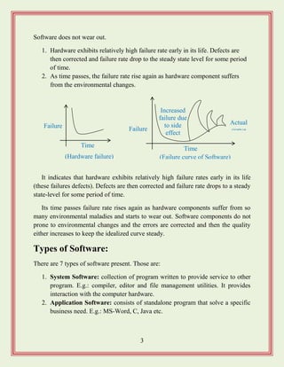
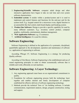
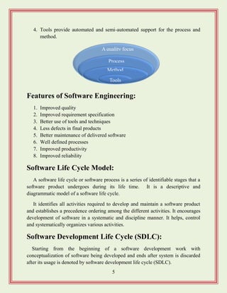
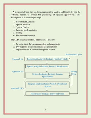
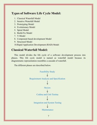
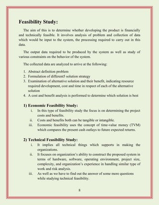
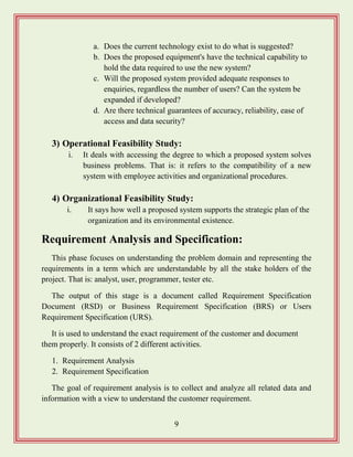
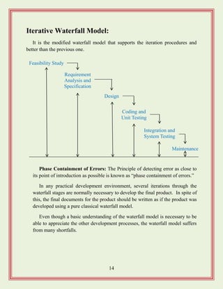
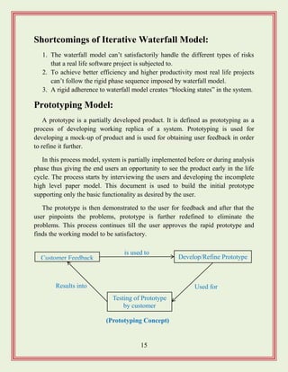
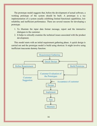
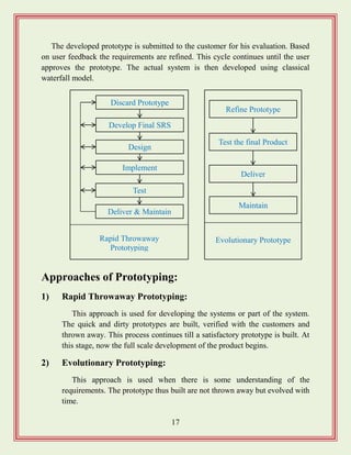
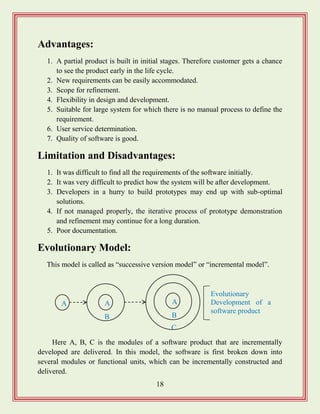
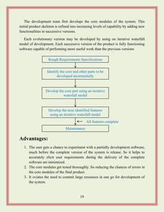
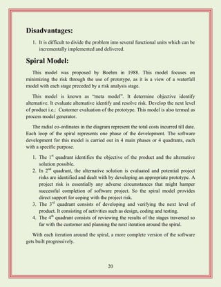
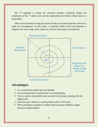
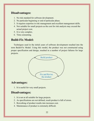
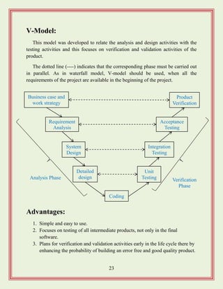
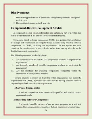
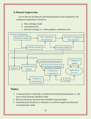
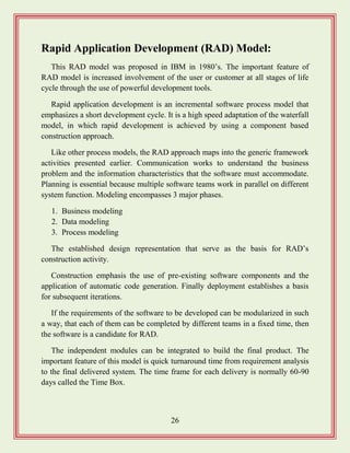
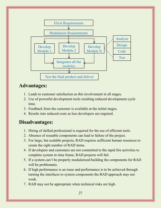
![35
Project planning:
It consists of essential activities. i.e.:
1. Estimating some basic attributes of the project
a. Cost: how much will it cost to develop the project
b. Duration: how long will it take to complete the development?
c. Effort: how much effort would be required?
d. The effectiveness of the subsequent planning activities is based on
the accuracy of these estimations.
2. Scheduling manpower and other resources
3. Staff organization and staffing plans
4. Risk identification, analysis and abatement planning.
5. Miscellaneous plans such as quality assurance plan, configuration
management plan etc.
The Software Project Management Plan (SPMP)
document:
After completion of project planning, project manager, document the result of
the planning phase on software project management plan (SPMP) documents. It
includes the following items.
Effort Estimation Cost Estimation
Size Estimation
Duration
Estimation
Project
Staffing
Scheduling
[Precedence ordering among planning activities]](https://image.slidesharecdn.com/softwareengineeringstudymaterials-171005111336/85/Software-engineering-study-materials-36-320.jpg)
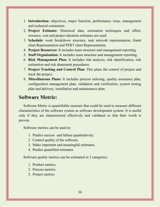
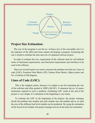
![42
Function Point Metric:
This overcomes from some of the shortcoming of LOC metric. It can be used to
estimate the size of the software directly from the problem specification.
The size of the product is directly dependent on the number and type of
different function it perform. In addition to this, it also depends on the no. of files
and no. of interfaces.
It computes the size of the software product using 5 different characteristics of
the product. The function point of given software is the weighted sum of the
following 5 items. That is: no. of inputs, no. of outputs, no. of inquiries, no. of files
and no. of interfaces. So the formula is:
Size of problem in FP‟s (unadjusted FP [UFP]) =
(No. of input) * 4 + (No. of output) * 5 + (No. of inquiries) * 4 + (No. of file) *
10 + (No. of interfaces) * 10.
Then the Technical Complexity Factor (TCF) is computed, measured by 14
other factors, such as high transaction rate, throughout, response time etc. Each of
the 14 factors is assigned a value 0 – 6. The resulting numbers are summed to give
the total degree of interfluence (DI) that vary from 0 – 70.
TCF = 0.65 + 0.01 * DI
FP = UFP * TCF
Advantages of Function Point Metric:
1. It is not restricted to code.
2. The language is independent.
3. The necessary data is available early in a project. Thus only a detailed
specification is required.
4. It is more accurate than LOC.
5. It can be used to easily estimate the size of the software product directly
from problem specification.](https://image.slidesharecdn.com/softwareengineeringstudymaterials-171005111336/85/Software-engineering-study-materials-43-320.jpg)
![43
Drawbacks of Function Point Metric:
1. Hard to automate and difficult to compute.
2. Ignores the quality of output.
3. It does not take into account the algorithmic complexity of software.
4. Oriented to traditional data processing application.
5. Subjective counting. i.e.: different people can come up with different
estimate for the same problem.
Feature Point Metric:
A major shortcoming of function point metric is that it does not take into
account the algorithmic complexity of software. To overcome from this the
“feature point metric” is introduced.
Feature point metric incorporates an extra parameter into algorithm complexity.
This parameter ensures that the computed size using the feature point metric
reflects the fact that the more complexity of a function greater the effort required to
develop it and therefore its size should be larger compared to similar functions.
Architectural Design Metrics:
This focuses on characteristics of the program architecture with an emphasis on
the architectural structure and effectiveness of modules or components within the
architecture.
These types of metrics are the black box in the sense that they don‟t require any
knowledge of inner workings of a particular software component. The complexity
measures are: Structural Complexity, Data Complexity and System Complexity.
For hierarchical architecture (e.g.: call and return), the structural complexity
of a module „i‟ is: S(i) = f2
out(i) [fout(i) = fan-out of i]
Data complexity provides an indication of the complexity in the internal
interface for a module „i‟ and is defined as:
D(i) = V(i)/(fout(i) + 1) [V(i) = no. of input and output variables in „i‟]](https://image.slidesharecdn.com/softwareengineeringstudymaterials-171005111336/85/Software-engineering-study-materials-44-320.jpg)
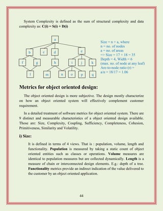
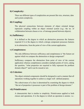
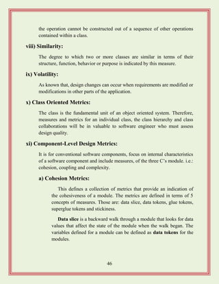
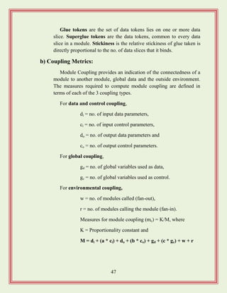
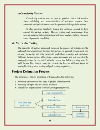
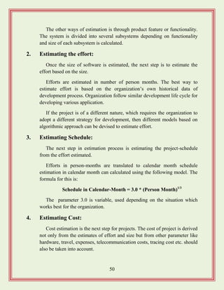
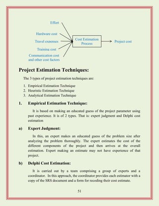
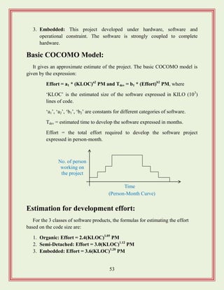
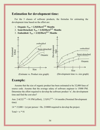
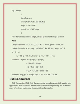
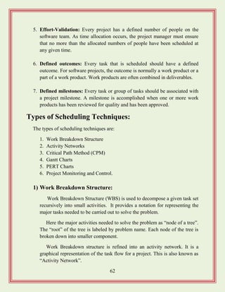
![63
2) Activity Networks:
WBS representation of a project is transformed into an activity network
by representing the activities identified in WBS along with their
interdependencies.
An activity network shows the different activities making up a project,
their estimated durations, and interdependencies. Managers can estimate the
time durations for the different tasks in several ways. One possibility is that
they can empirically assign durations to different tasks.
MIS
Application
Requirement
Analysis
DocumentDesign Code
Database
Part
Test
GUI
Part
GUI
Part
Database
Part
[Work Breakdown Structure for MIS (management information system) Software]
Design database
part 45
Specification 15
Finish 0
Design GUI
part 30
Code GUI part
45
Write user manual 60
Integrate and Test 120
[Activity network representation of the MIS problem ]
Code database
part 105](https://image.slidesharecdn.com/softwareengineeringstudymaterials-171005111336/85/Software-engineering-study-materials-64-320.jpg)
![65
length of time each task is estimated to take. The white part shows the slack
time, which is the latest time by which a task must be finished.
5) PERT Charts:
PERT (Project Evaluation and Review Technique) charts consist of a
network of boxes and arrows. The boxes represent activities and the arrows
represent task dependencies.
PERT chart represents the statistical variations in the project estimates
assuming a normal distribution. Thus in PERT chart instead of making a
single estimate for each task, pessimistic, likely and optimistic estimates are
also made.
The boxes of PERT charts are usually annotated with the pessimistic,
likely and optimistic estimates for every task.
All possible completion times between the minimum and maximum
durations for every task have to be considered, there is not one but many
Jan 1
Design database
Part
Design GUI
Part
Integrate and
Test
[Gantt chart representation of the MIS problem]
Code database
part
Specification
Write user manual
Jan 15 July 15Apr 15 Nov 15Mar 15](https://image.slidesharecdn.com/softwareengineeringstudymaterials-171005111336/85/Software-engineering-study-materials-66-320.jpg)
![66
critical paths, depending on the permutations of the estimates for each task.
This makes critical path analysis in PERT charts very complex.
A critical path in a PERT chart is shown by using thicker arrows. PERT
charts are a more sophisticated form of activity chart. In activity diagram
only the estimated task durations are represented.
Gantt chart representation of a projected schedule is helpful in planning
the utilization of resources, while a PERT chart is useful for monitoring the
timely progress of activities. It is easier to identify parallel activities in a
project using a PERT chart.
Project Monitoring and Control:
Once the project gets under-away, the project manager has to monitor the
project continuously to ensure that it progresses as per the plan. The project
manager designates certain key events such as completion of some important
activities as milestones.
Design database part
40, 45, 60
Specification
12, 15, 20
Finish 0
Design GUI part
24, 30, 38
Code GUI part
38, 45, 52
Write user manual
50, 60, 70
Integrate and Test
100, 120, 140
[PERT chart representation of the MIS problem ]
Code database part
95, 105, 120](https://image.slidesharecdn.com/softwareengineeringstudymaterials-171005111336/85/Software-engineering-study-materials-67-320.jpg)
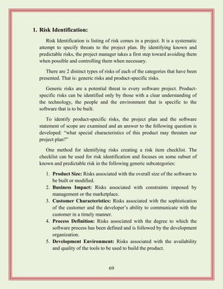
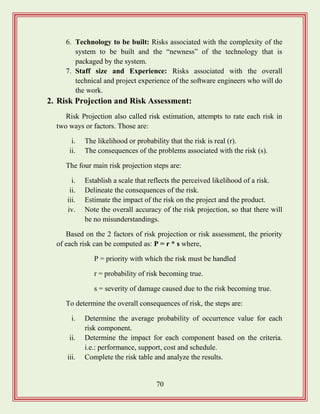
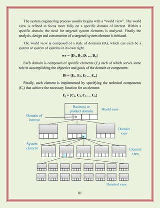
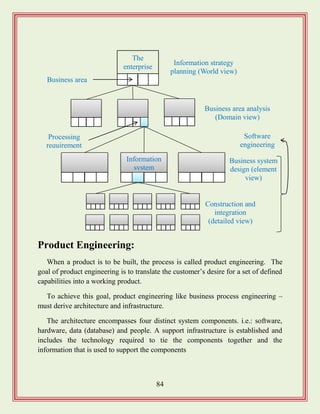
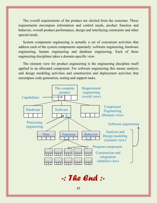
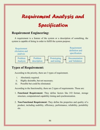
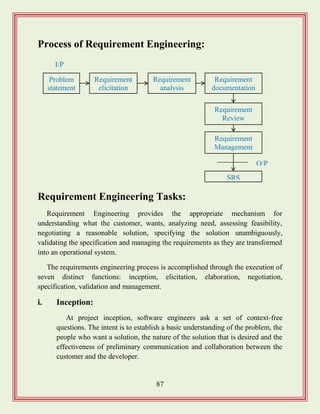
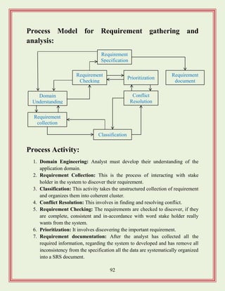
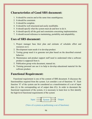
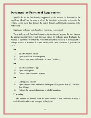
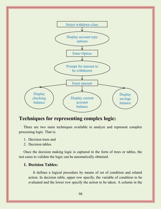
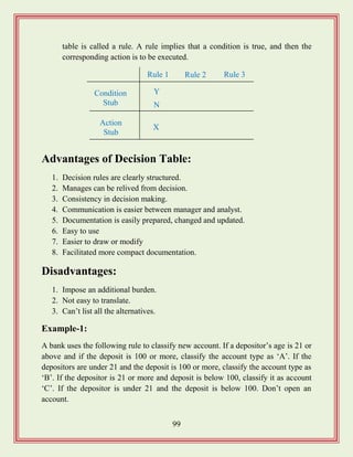
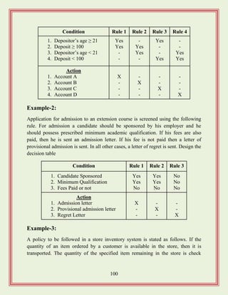
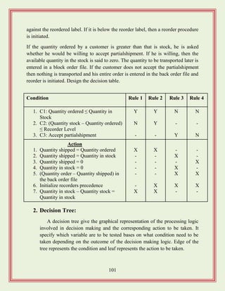
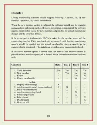
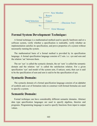
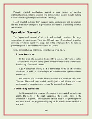
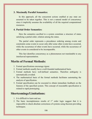
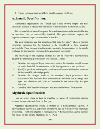
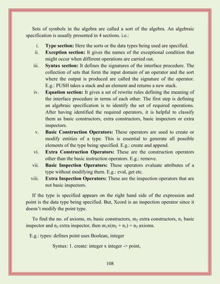
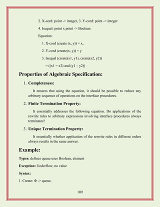
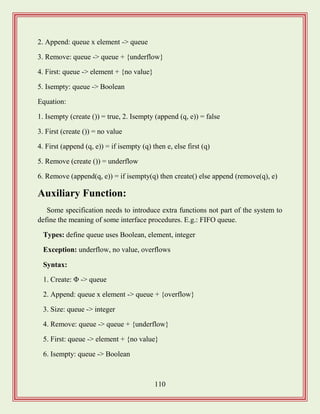
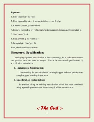

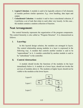
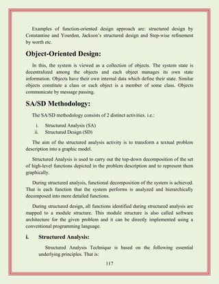
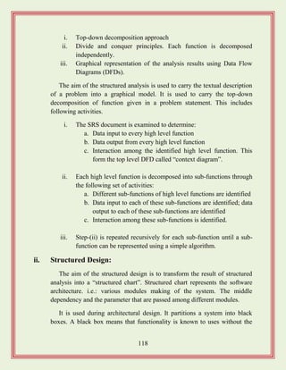
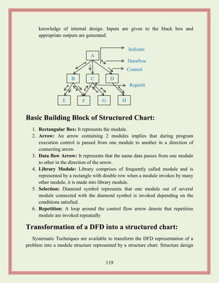
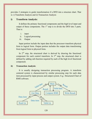
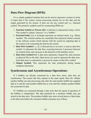
![122
Data Dictionary:
It lists all the data item appearing in the DFD. i.e.: a data dictionary contains all
data flow and the contents of all data store appearing on the DFD.
A data dictionary lists the purpose of all data item and the definition of all
composite data item in term of their component data item. E.g.: gross pay of
employee. A data dictionary is important in the software development process
because of the following reason.
It lists standard terminology for all related data for used by engineer working on
a project. It provides the analyst with means to determine the definition of different
data structure in terms of their component element.
Data Definition:
Composite data are defined in terms of primitive data item, using the following
data definition operator. Those are:
1. „+‟ operator: It represents the composition of data.
2. [, ,]: It represents the selection. E.g.: [a, b].
3. {}: It represents the iterative data definition. E.g.: {name}, 5:- 5 names are
to be stored.
4. (): The content inside the bracket represent the optional data which may or
may not appear.
5. =: Equivalence
6. /* */: Comment
Balancing DFDs:
The data that flow into or out of a bubble must match the dataflow at the next
level of the DFD. This is known as “balancing the DFD”.
i. Numbering of bubbles: The bubble at the context level is assigned the
number zero to indicate that it is zero level DFD. The bubbles at level 1
are numbered as 0.1, 0.2, 0.3 etc. The bubbles at level 2 are numbered as:
0.2.1, 0.2.2, 0.2.3, 0.2.4, 0.2.5 etc.](https://image.slidesharecdn.com/softwareengineeringstudymaterials-171005111336/85/Software-engineering-study-materials-123-320.jpg)
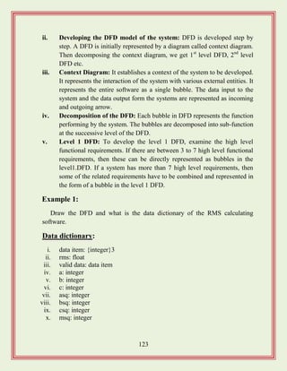
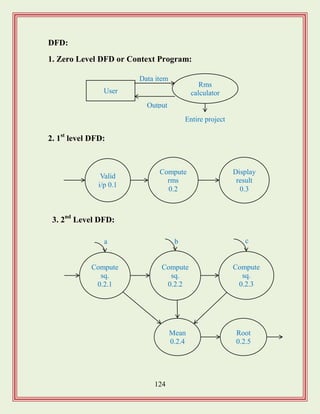
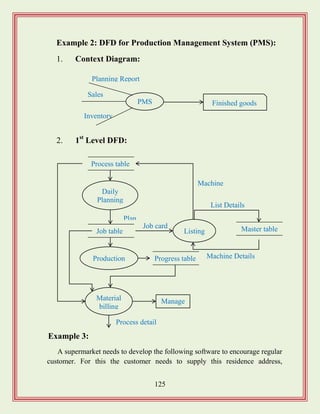
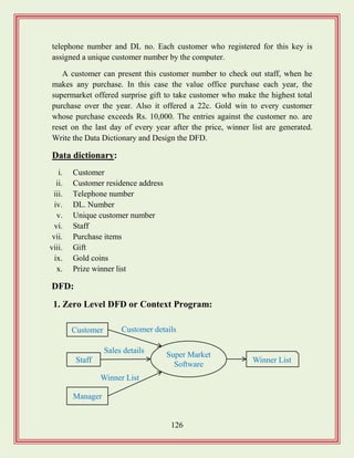
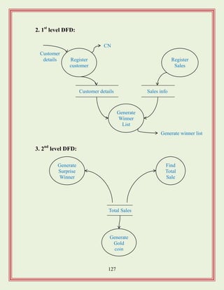
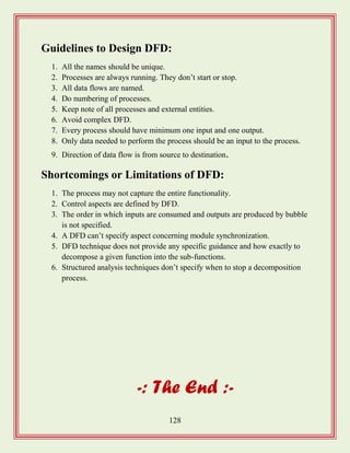
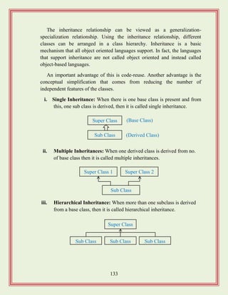
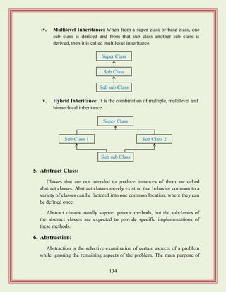
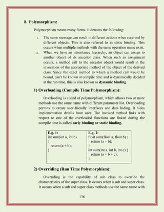
![137
identical signatures such that sub class hides the super class method. It
is called run time polymorphism.
In overriding, since the sub and super class objects have it
signature of a particular method, the type of actual object, which calls
the method, which is identified at run time. It is otherwise called as
dynamic binding.
Example:
class excel
{
void display title ()
{
system.out.println (“Microsoft excel”);
}
}
class workbook extends excel
{
void display title ()
{
super.displaytitle ();
system.out.println (“Book1”);
}
}
class AB
{
public static void main (string args [])
{
workbook book1 = new workbook ();
book1.display ()
}
}
9. Composite Objects:
Objects which contain other objects are called composite objects.
Containment may be achieved by including the pointer to one object as a](https://image.slidesharecdn.com/softwareengineeringstudymaterials-171005111336/85/Software-engineering-study-materials-138-320.jpg)
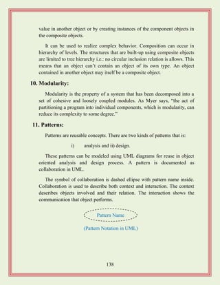
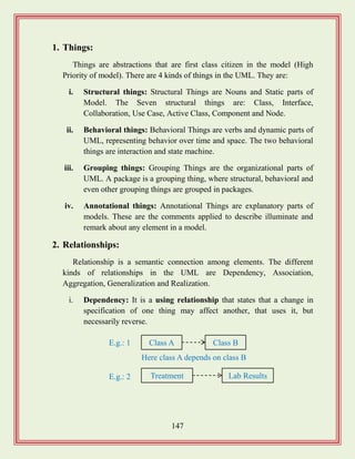
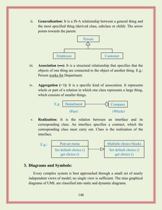
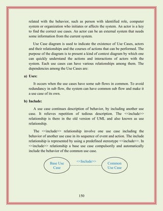
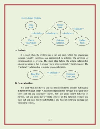
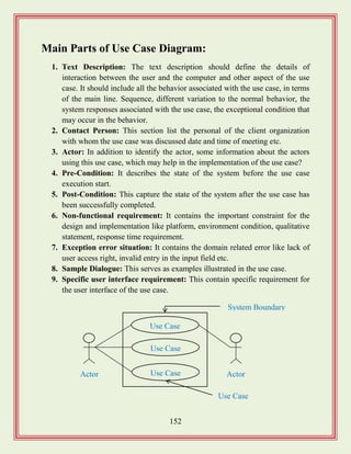
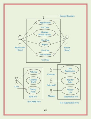
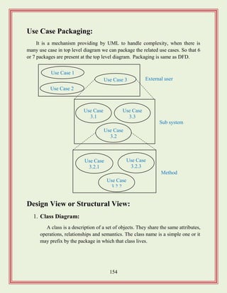
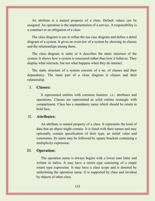
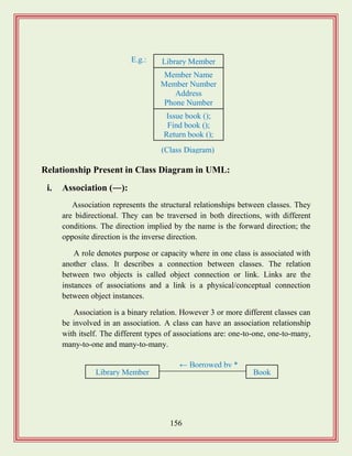
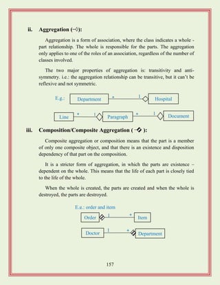
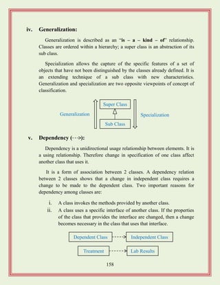
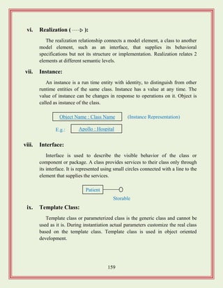
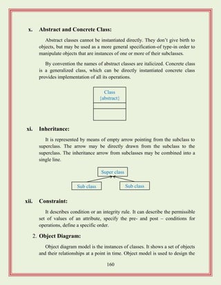
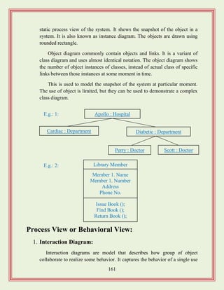
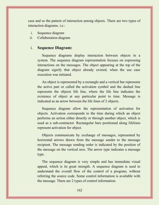
![163
a. Condition: that indicates that a message is send.
b. An interaction marker (*): show that the message is sent
many times to multiple receiver objects.
Patient Appointment Doctor Treatment
Confirms
Diagnosed
by
Gives
treatment
Feedback
Example:
: Library
Boundary
: Lib Book
Register
: Lib Book Renew
Controller
: Book
: Lib
Member
Renew book
Display
borrowing
Select
Book
Apology
Confirm
Find mem
Borrowing
Book
selected
Apology
Confirm
*find
Update
Updat
e
Member Borrowing
[Sequence Diagram of Database and the table of Library System]](https://image.slidesharecdn.com/softwareengineeringstudymaterials-171005111336/85/Software-engineering-study-materials-164-320.jpg)
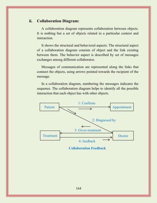
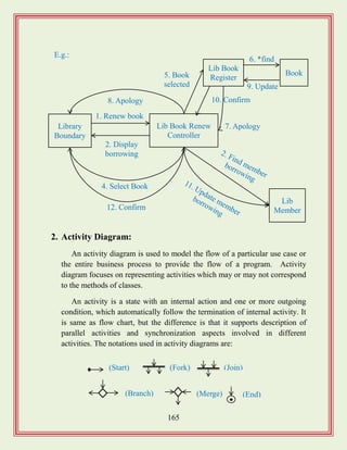
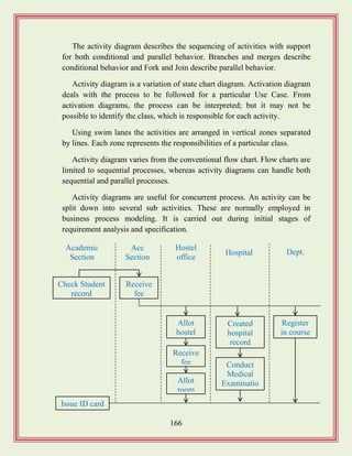
![167
3. State Chart Diagram:
Sometimes, it is desirable to model the behavior of a single object class,
especially if the class illustrates significant dynamic behavior. State
chart/State Transition diagram may be created for these types of classes.
It shows a life history of a given class, the events that causes a transition
from one state to another, and the action that results from a state change. So
the state chart diagrams are useful to model the reactive systems.
It is used to model how the state of an object changes in its life time.
These are good at describing how the behavior of an object changes across
several use case execution. Reactive systems can be defined as a system that
corresponds to external or internal events.
Classify
diabetic type
Study the
patient History
Prescribe
for lab test
Treatment
for diabetic
Classify the
patient work type
Check height
and weight
No treatment Next
Person in the queue
Branch
No symbols
State
(End)
[Activity Diagram of Diagnosis of Diabetic Patient]](https://image.slidesharecdn.com/softwareengineeringstudymaterials-171005111336/85/Software-engineering-study-materials-168-320.jpg)
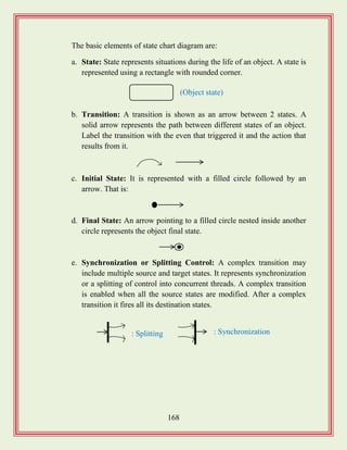
![169
Implementation View and Deployment View:
1. Implementation Diagrams:
Implementation diagrams show the implementation phase of system
development and its architecture. Implementation is described by physical
and logical structure.
Unprocessed
order
Rejected
order
Accepted
order
[Reject]
checked
[Accept]
checked
Accepted
order
Accepted
order
[All time available]
new supply
[Sometimes
not available]
Processed
[All items available]
Processed or deliver
Order received
Idle
Send order
request
Selected special or
normal order
Order confirmation
Dispatch order
Confirm order
Transitio
n
Transaction CompleteFinal state
Initial state
Initial state of
the object](https://image.slidesharecdn.com/softwareengineeringstudymaterials-171005111336/85/Software-engineering-study-materials-170-320.jpg)
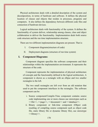
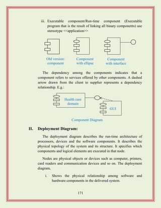
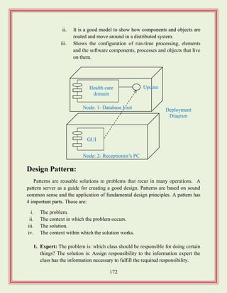
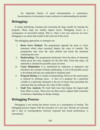
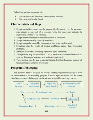
![183
b) Dynamic Analysis Tool:
This technique requires the program to be executed and its actual
behavior recorded. A dynamic analyzer usually instruments the code of the
software to be tested in order to record the behavior of the software for
different test cases.
After the software is tested and behavior is recorded, dynamic analysis
tool carried out a post execution analysis and produces reports which
describe the structured coverage that has been achieved by the complete test
suite for the program.
Testing:
It is a program, consists of providing the program with a set of test inputs and
observing if the program behaves as expected some commonly used terms
associated with testing.
The aim of the testing process is to identify all defects existing in a software
product. Some commonly used testing associated with testing are:
a. Failure: It is a manifestation of an error. It is the ability of the software to
perform a required function to its specification.
b. Fault: It is an incorrect intermediate state that may have been entered during
program execution. E.g.: a variable value is different from what it should be.
c. Test Cases: It is the triplet [1, S, 0] where „1‟ is the data input to the system
„S‟ is the state of the system at which the data is input and „0‟ is the expected
output of the system.
d. Test Suite: It is the set of all test cases with which as given software product
is to be tested.
Characteristics of Testing:
1. To perform effective testing, a software team should conduct effective
formal technical review.](https://image.slidesharecdn.com/softwareengineeringstudymaterials-171005111336/85/Software-engineering-study-materials-184-320.jpg)
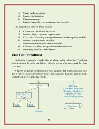
![188
Driver and Stub Modules:
In order to test a single module, we need a complete environment to provide.
i.e.: necessary for executing a module. That is besides the module under test itself;
we need the following in order to be able to test the module.
i. The procedure belonging to other modules that the module under test calls.
ii. Nonlocal data structures that the module accesses.
iii. A procedure to call the functions of the module under test with appropriate
parameters.
Modules required to provide the necessary environment are usually not
available until they have been unit tested; so stub and driver are designed to
provide complete environment for a module.
A stub procedure is dummy procedure that has the same I/O parameters as the
given procedure but has a highly simplified behavior. A driver module would
contain the nonlocal data structures accessed by the module under test and would
also have the code to call the different functions of the module with appropriate
parameter values.
Drivers and stubs represent overhead. That is both are software that must be
written but that is not delivered with the final software product. If drivers and stubs
are kept simple, actual overhead is relatively low.
Unit testing is simplified when a component with high cohesion is designed.
When only one function is addressed by a component, the number of test cases is
reduced and errors can be more easily predicted and uncovered.
Driver
Module under test
Stub Module
Global data
[Unit testing with the help of driver and stub module]](https://image.slidesharecdn.com/softwareengineeringstudymaterials-171005111336/85/Software-engineering-study-materials-189-320.jpg)
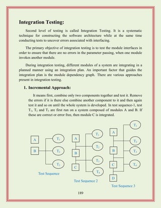
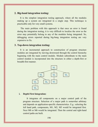
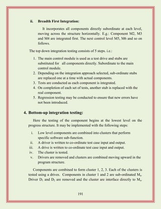
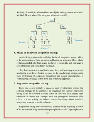
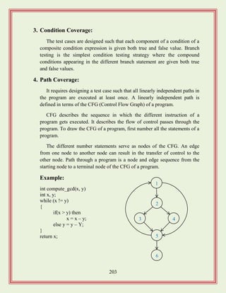
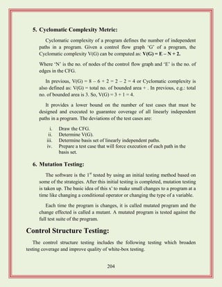
![205
1. Condition testing:
Condition testing is a test design method that exercises the logical
conditions contained in a program module. A simple condition is a Boolean
variable or a relational expression, possibly preceded with one NOT(¬)
operator.
A relational expression takes form: E1<relational-operator>E2, where E1
and E2 are arithmetic expressions and <relational-operator> is one of the
following: <, ≤ , =, ≠, >, ≥. A compound condition is composed of two or
more simple conditions, Boolean operators and parenthesis.
2. Data Flow Testing:
The dataflow testing method selects test paths of a program according to
the locations of definitions and uses of variables in the program.
To illustrate the dataflow testing approach, assume that each statement in
a program is assigned a unique statement number and that each function
doesn‟t modify its parameters or global variables.
For a statement with „S‟ as its statement number,
DEF(S) = {X | statement S contains a definition of X}
USE(S) = {X | statement S contains a use of X}
If statement „S‟ is if or loop statement, its DEF set is empty and its USE
set is based on the condition of statement S.
The definition of variable X at statement S is said to be live at statement
S' if there exists a path from statement S to statement S' that contains no
other definition of X.
A definition-use (DU) chain of variable X is of the form [X, S, S'], where
S and S' are statement numbers, X is in DEF(S) and USE(S') and the
definition of X in statement „S‟ is live at statement S'.](https://image.slidesharecdn.com/softwareengineeringstudymaterials-171005111336/85/Software-engineering-study-materials-206-320.jpg)
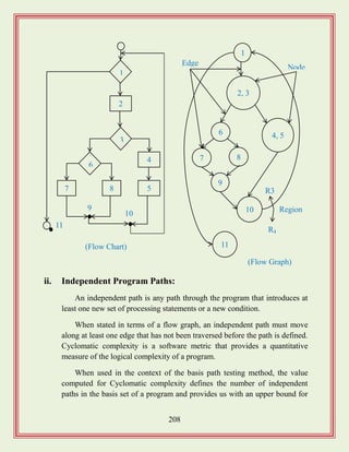
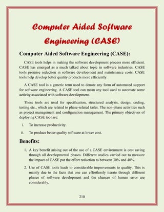
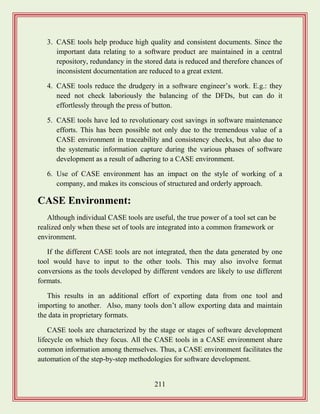
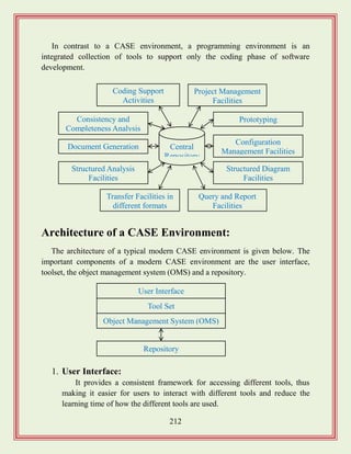
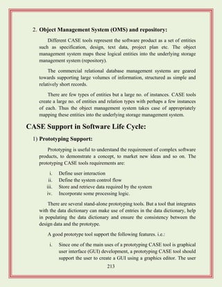
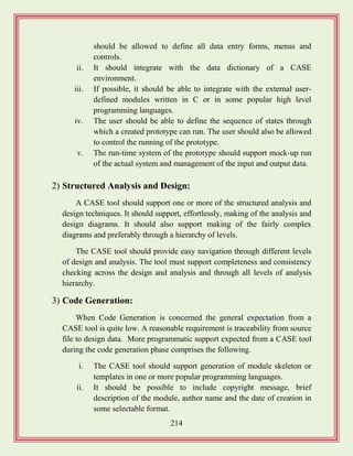
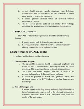
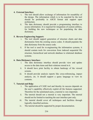

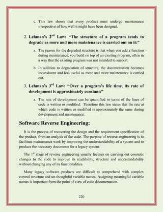
![221
After the cosmetic changes have been carried out the process of extracting code,
design and the requirement specification begins.
In order to extract the design, a full understand of the code is needed. Some
automatic tools can be used to derive the data flow and the control flow diagram
from the code.
Software Maintenance Process Model:
The activities involved in a software maintenance project are not unique and
depend on several factors such as:
i. The extent of modification to the product required.
ii. The resources available to the maintenance team.
iii. The conditions of the existing product.
iv. The expected project risks.
For complex maintenance projects for legacy systems, the software process can
be represented by a reverse engineering cycle followed by a forward engineering
cycle with an emphasis on as much reuse as possible from the existing code and
other documents. There are 2 broad categories of process models is proposed.
Requirement Specification
Design
Module Specification
Code
[Process Model of Revenue Engineering]
Reformat
Program
Assign
Meaningful
names
Simplify
Conditions
Remove
GOTOs
Simplify
Processing](https://image.slidesharecdn.com/softwareengineeringstudymaterials-171005111336/85/Software-engineering-study-materials-222-320.jpg)
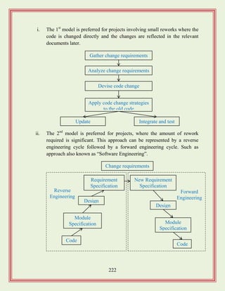
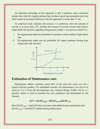
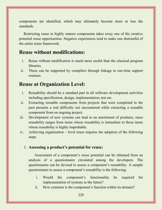
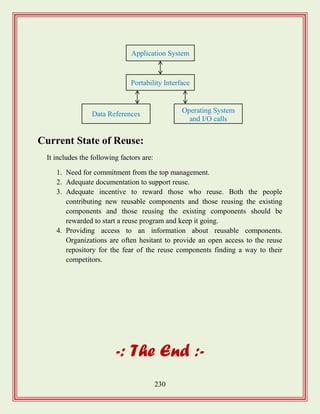
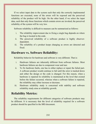
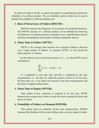
![235
Reliability Growth Modeling:
A reliability growth model is a mathematical model of how reliability improves
as errors are detected and repaired. A reliability growth model can be used to
predict when a particular level of relatively is likely to be attained. Thus, reliability
growth modeling can be used to determine when to stop testing to attain a given
reliability.
Jelinski and Moranda Model:
The simplest reliability growth model is a step function model where it is
assumed that the reliability increases by a constant increment each time an error is
detected and repaired.
This simple model of reliability which implicitly assumes that all errors
contribute equally to reliability growth is highly unrealistic since, we already know
that corrections of different errors contribute differently to reliability growth.
Littlewood and Verall‟s Model:
This model allows for negative reliability growth to reflect the fact that when a
repair is carried out, it may introduce additional errors. It also models the fact that
as errors are repaired, the average improvement in reliability per repair decreases.
It treats an errors contribution to reliability improvement to be an independent
random variable having Gamma distribution. This distribution models the fact that
error corrections with large contributions to reliability growth are removed first.
ROCOF
Time
[Step Function Model of Reliability Growth]](https://image.slidesharecdn.com/softwareengineeringstudymaterials-171005111336/85/Software-engineering-study-materials-236-320.jpg)
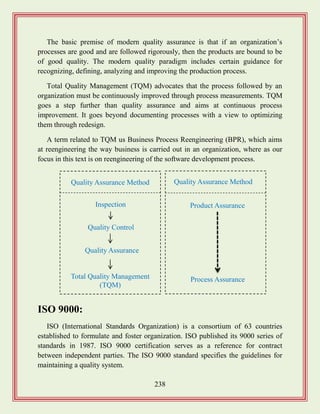
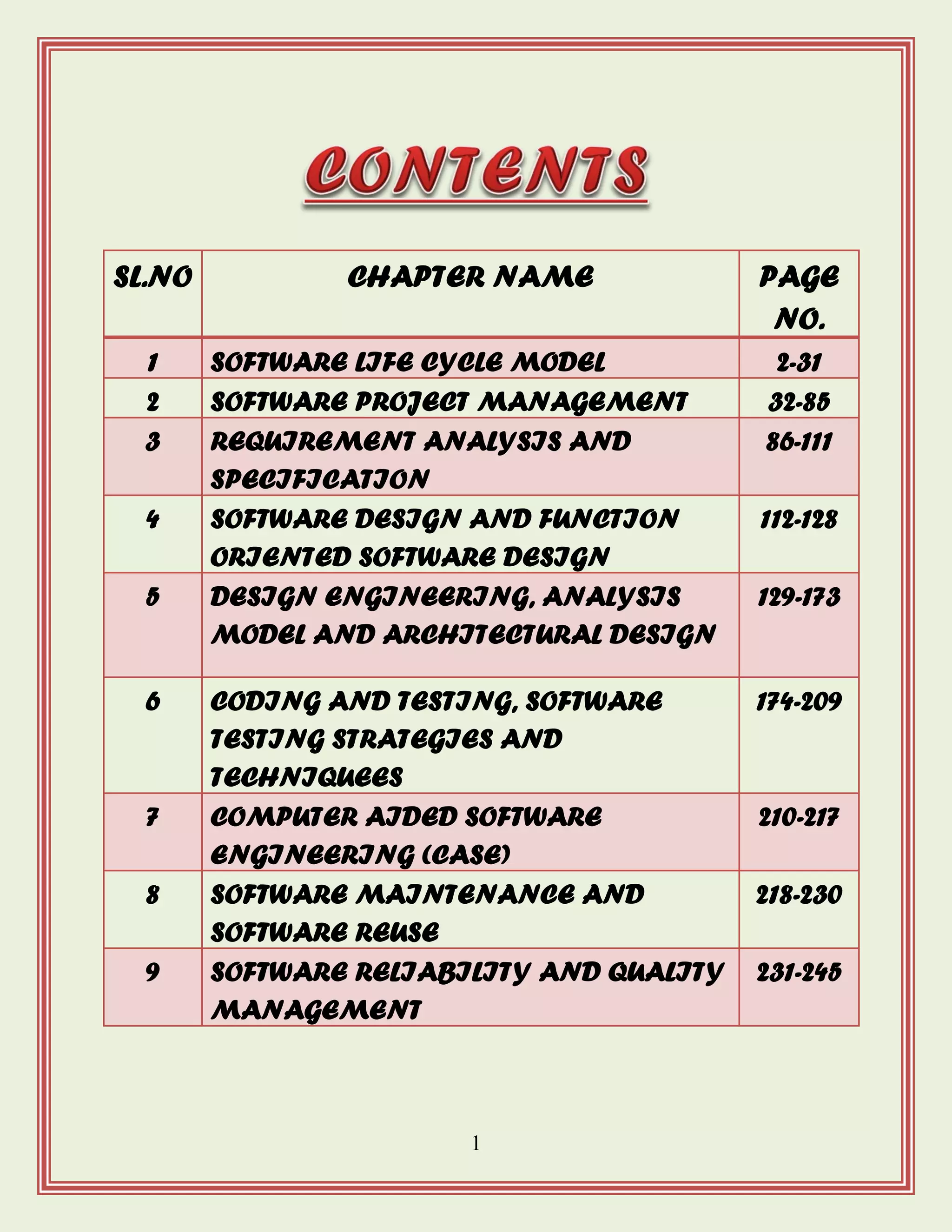
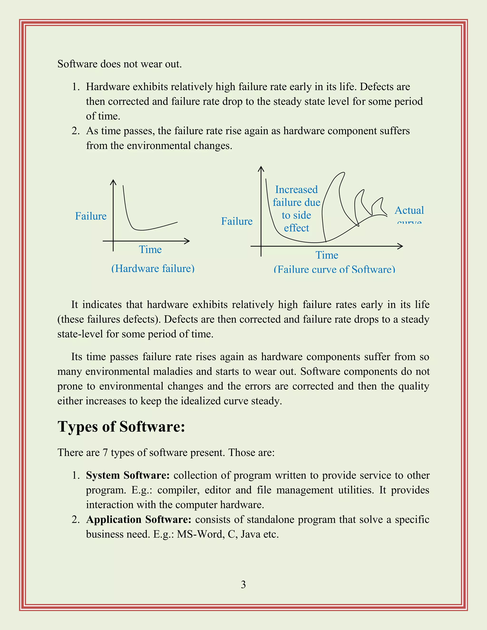
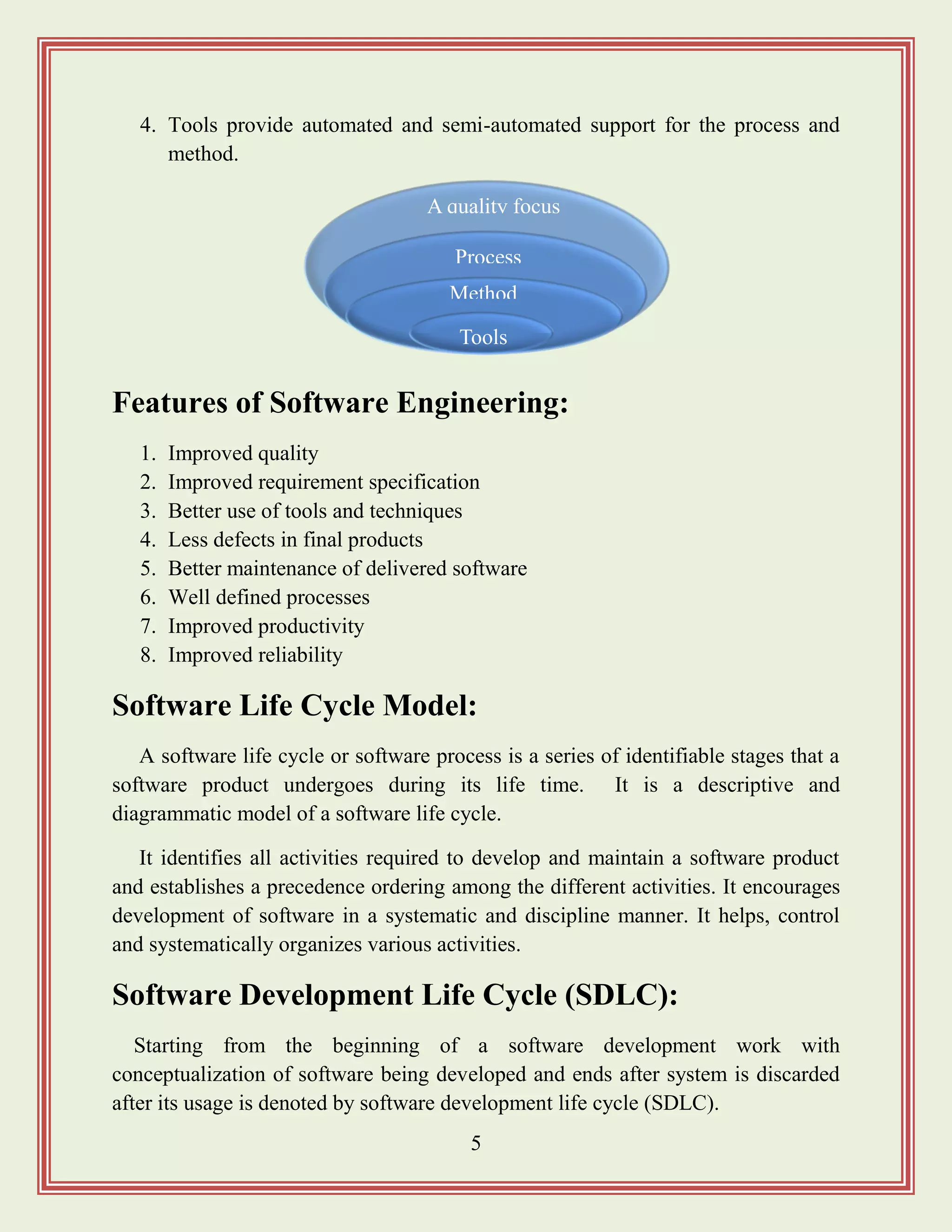
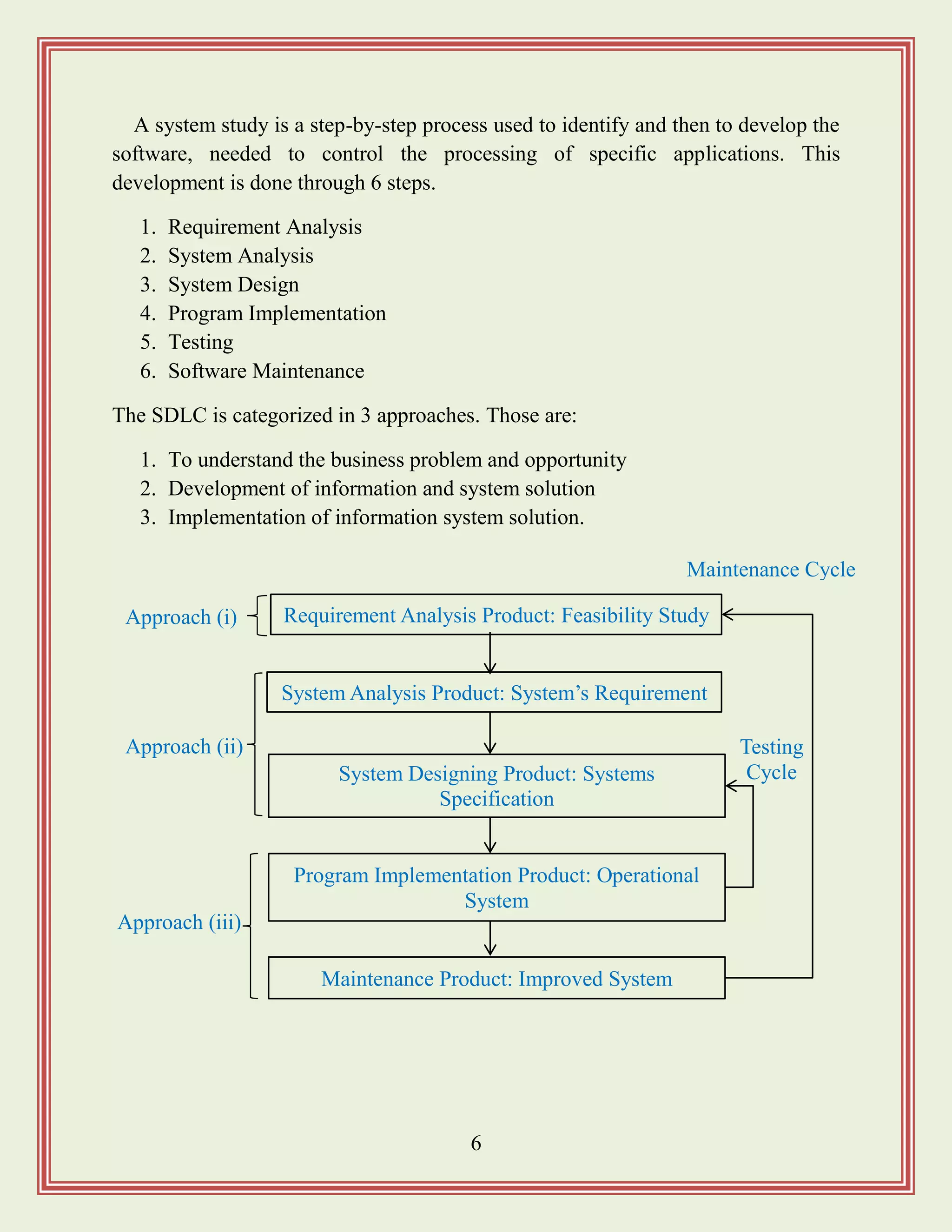
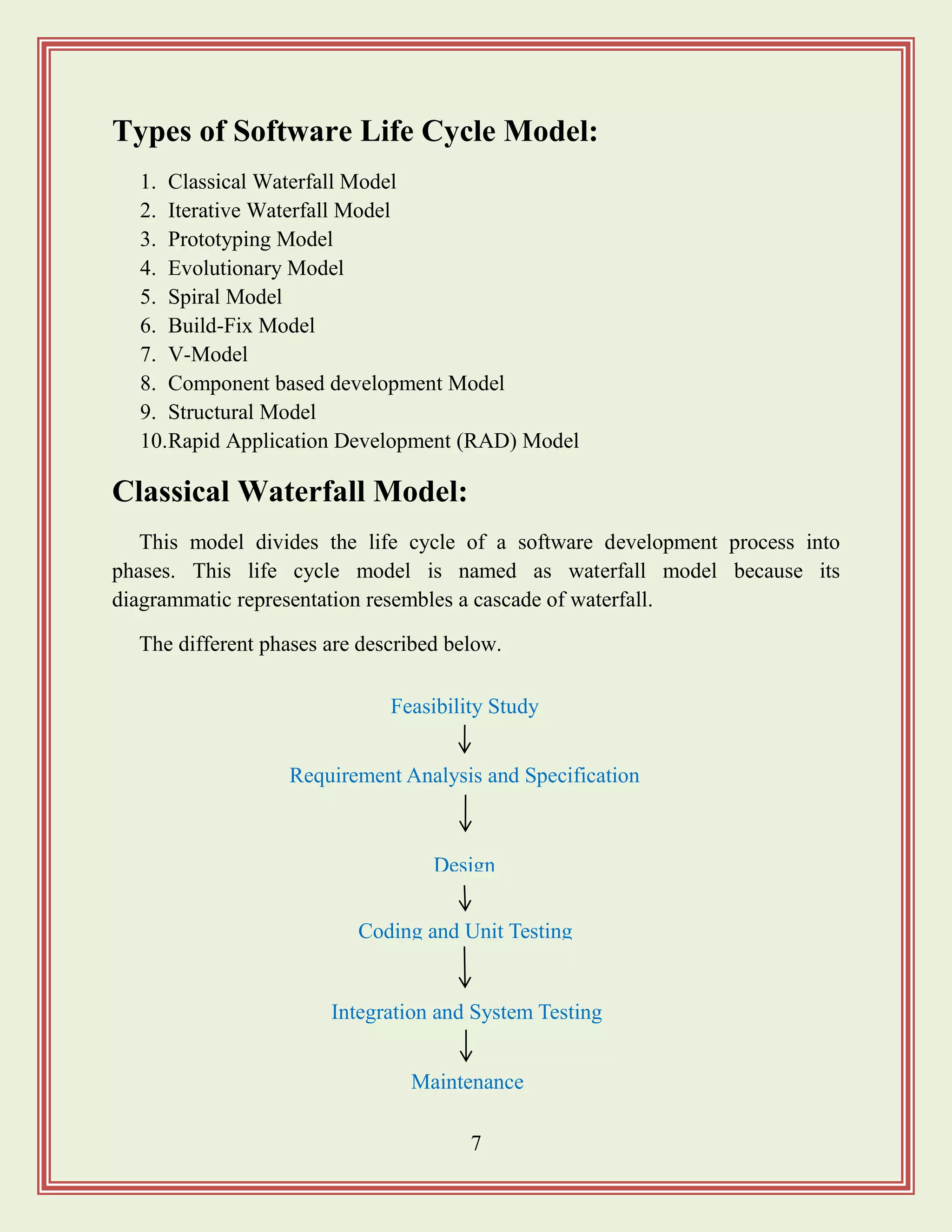
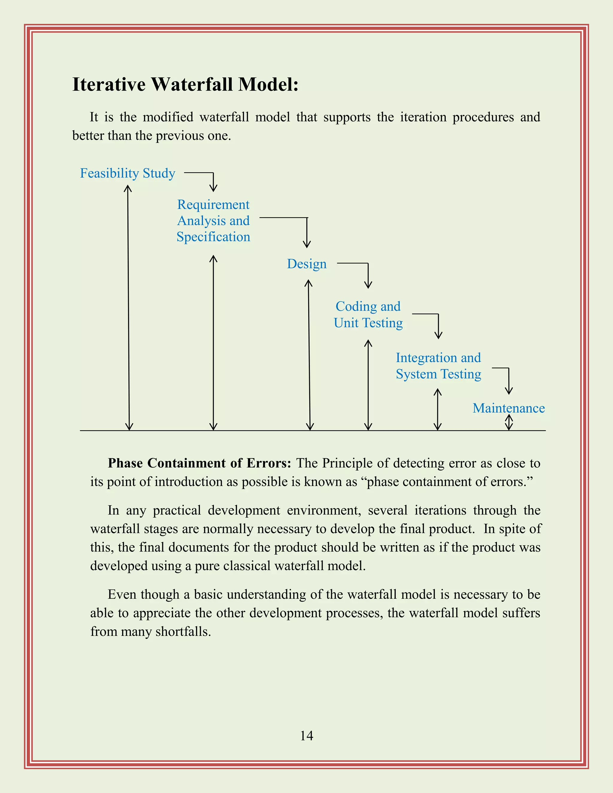
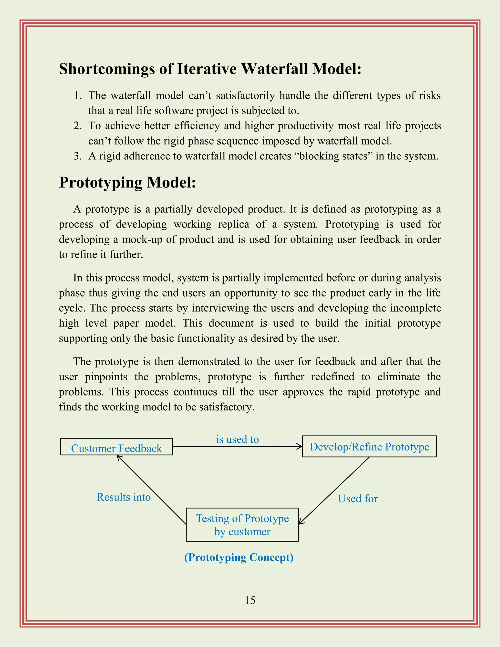
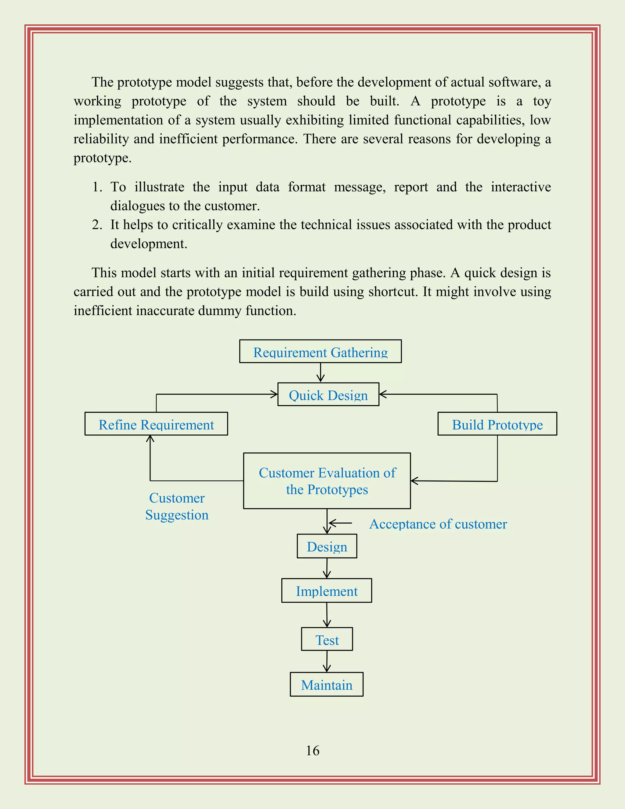
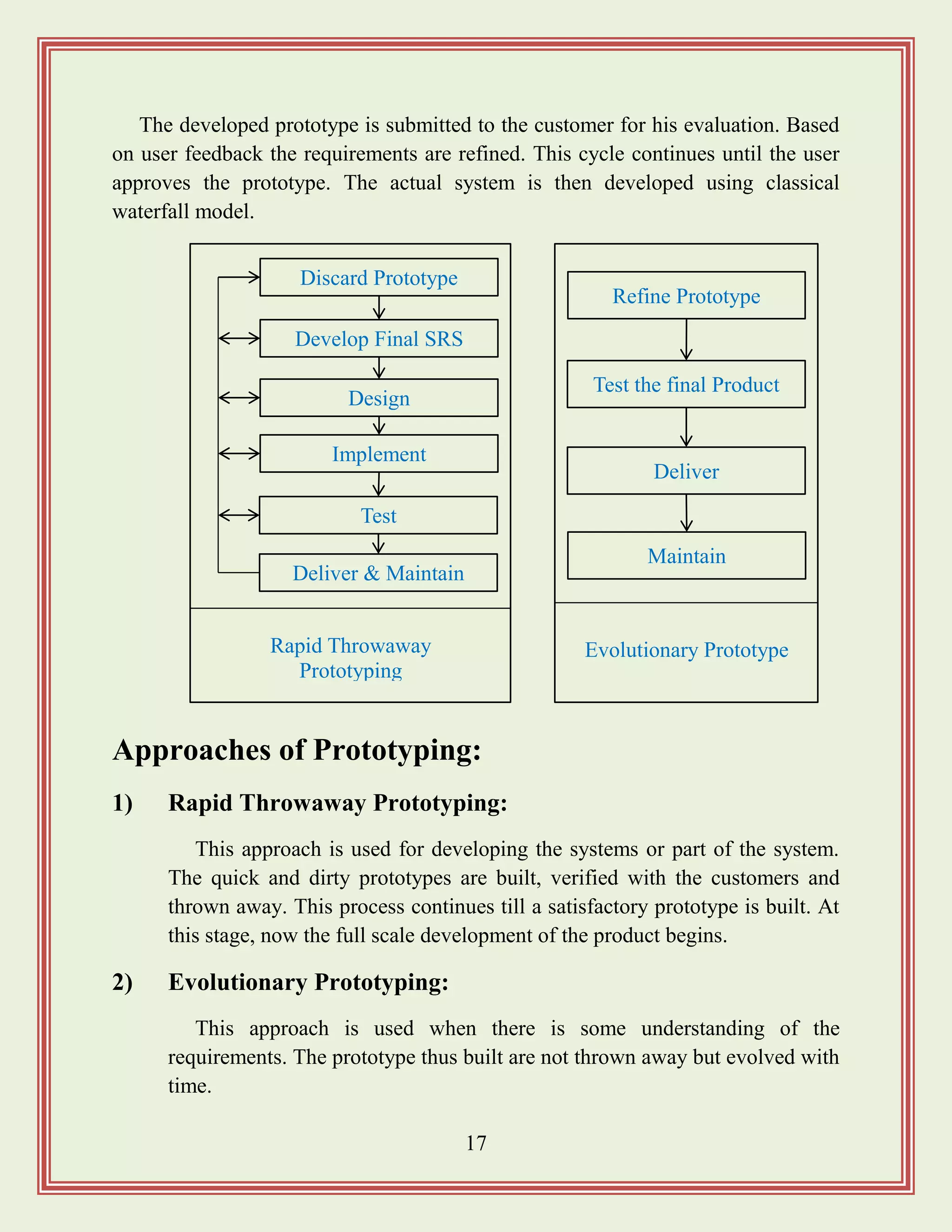
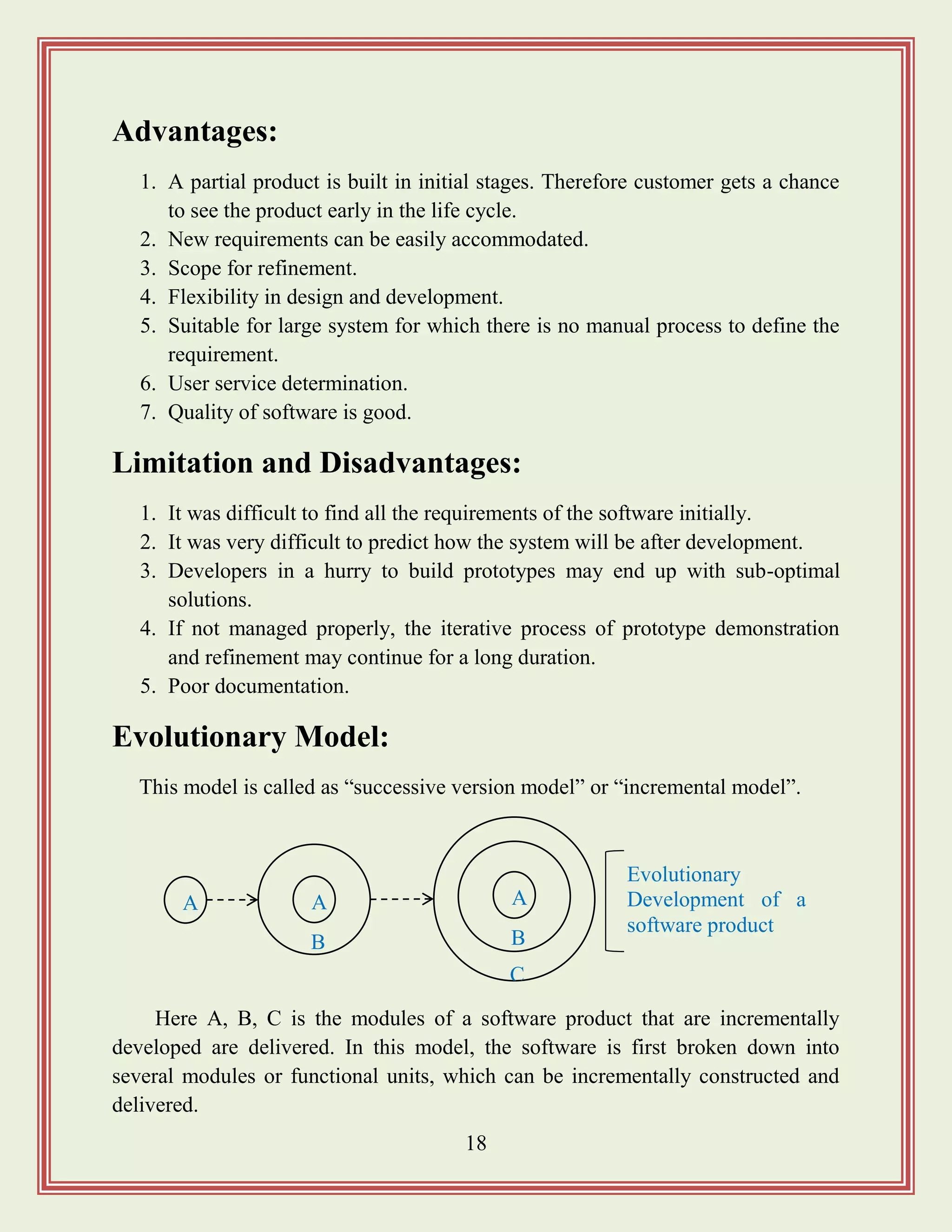

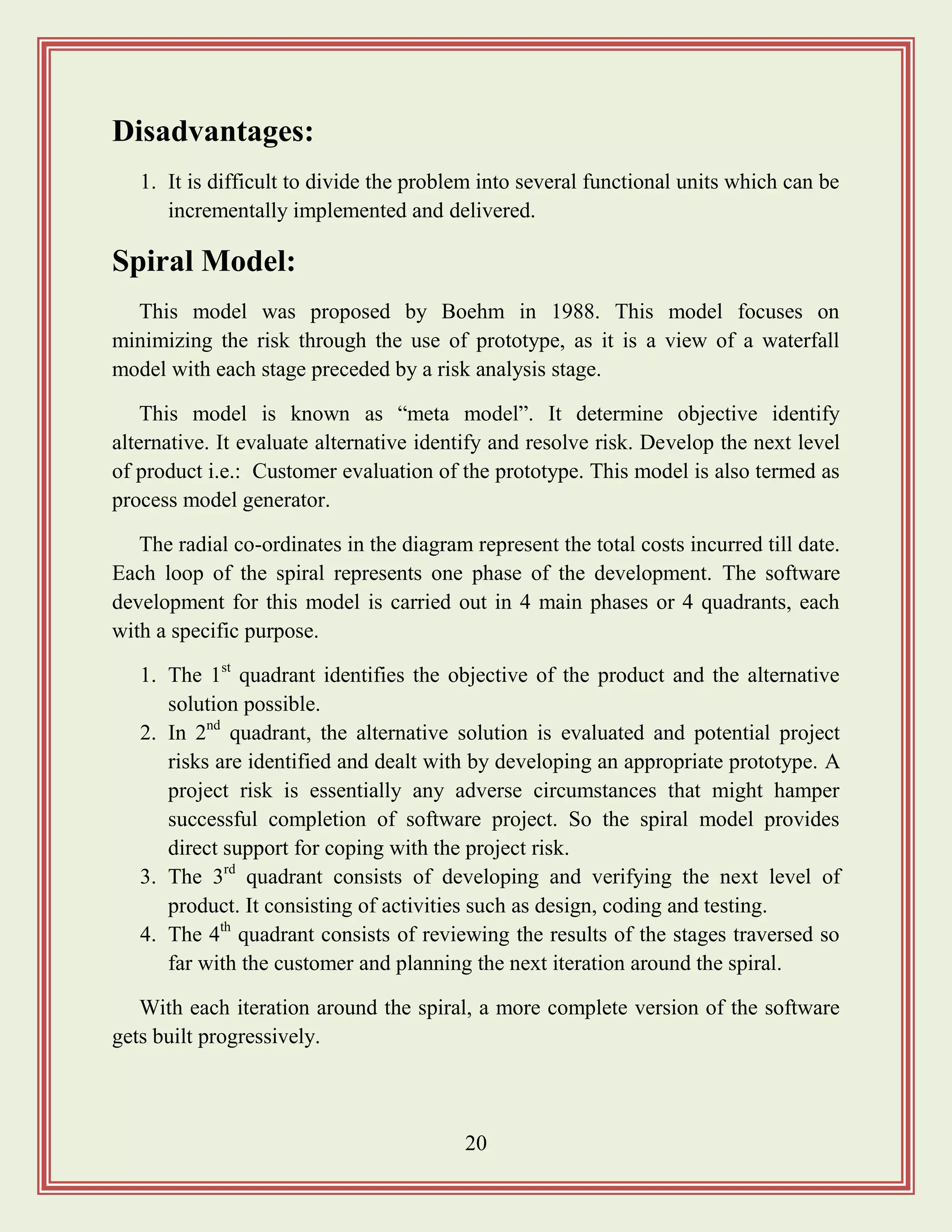
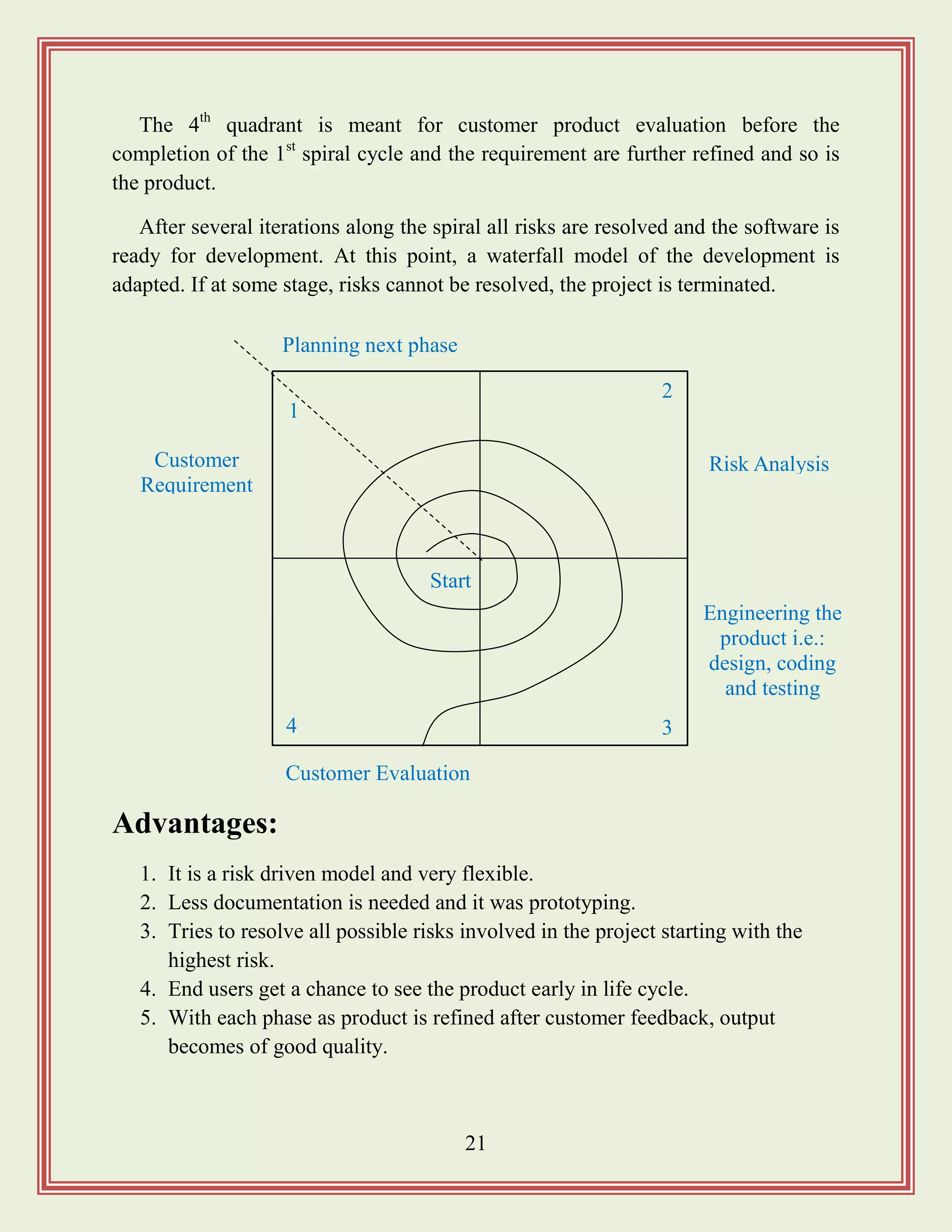
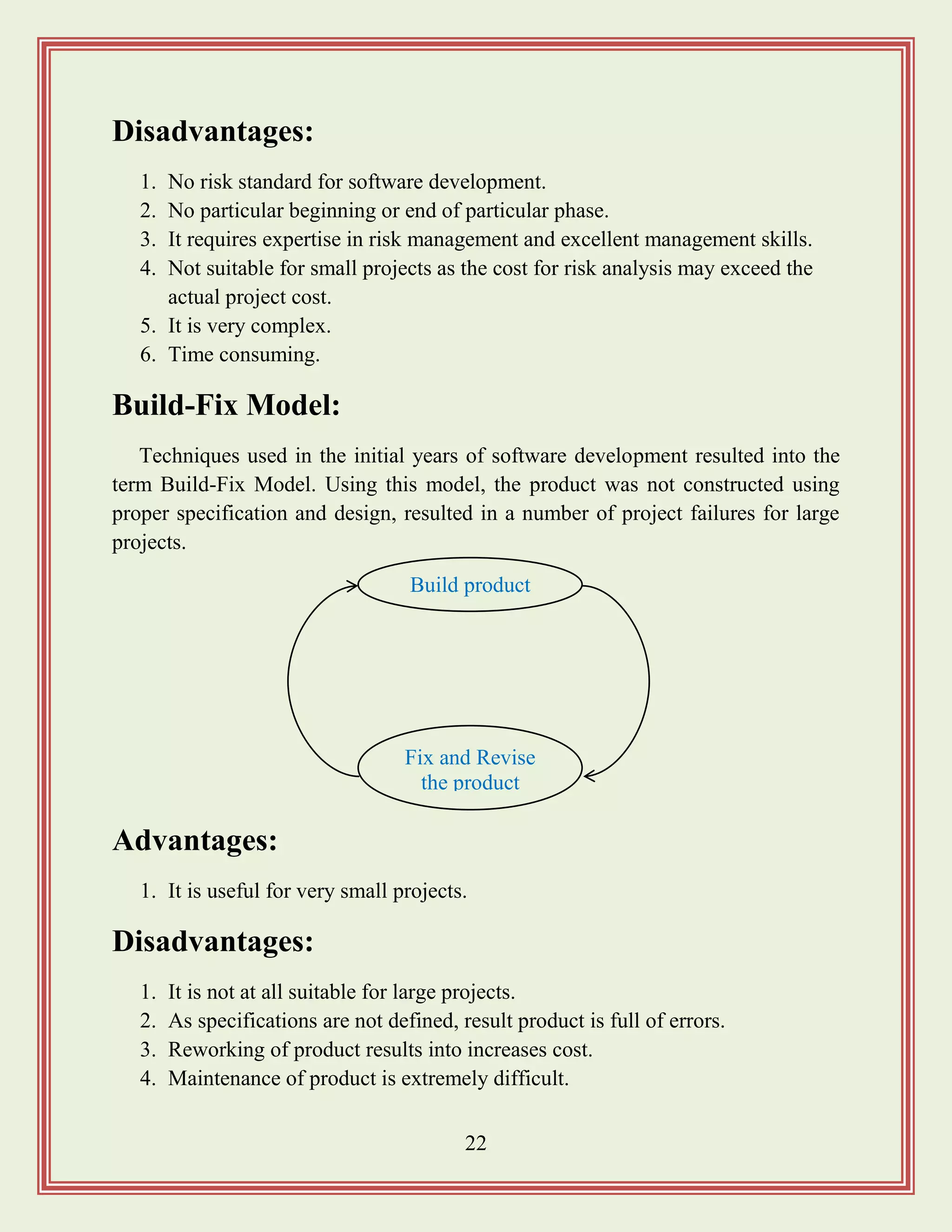
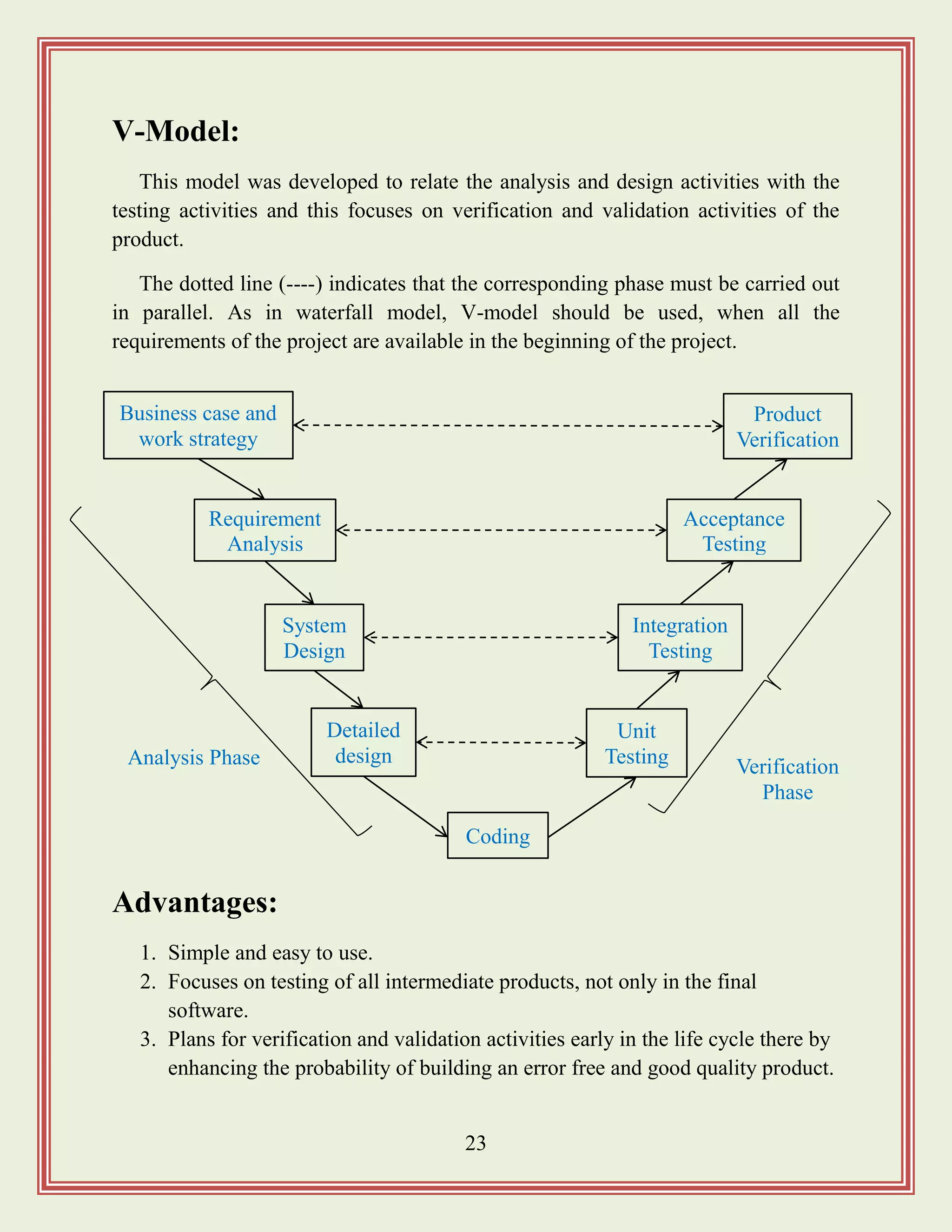
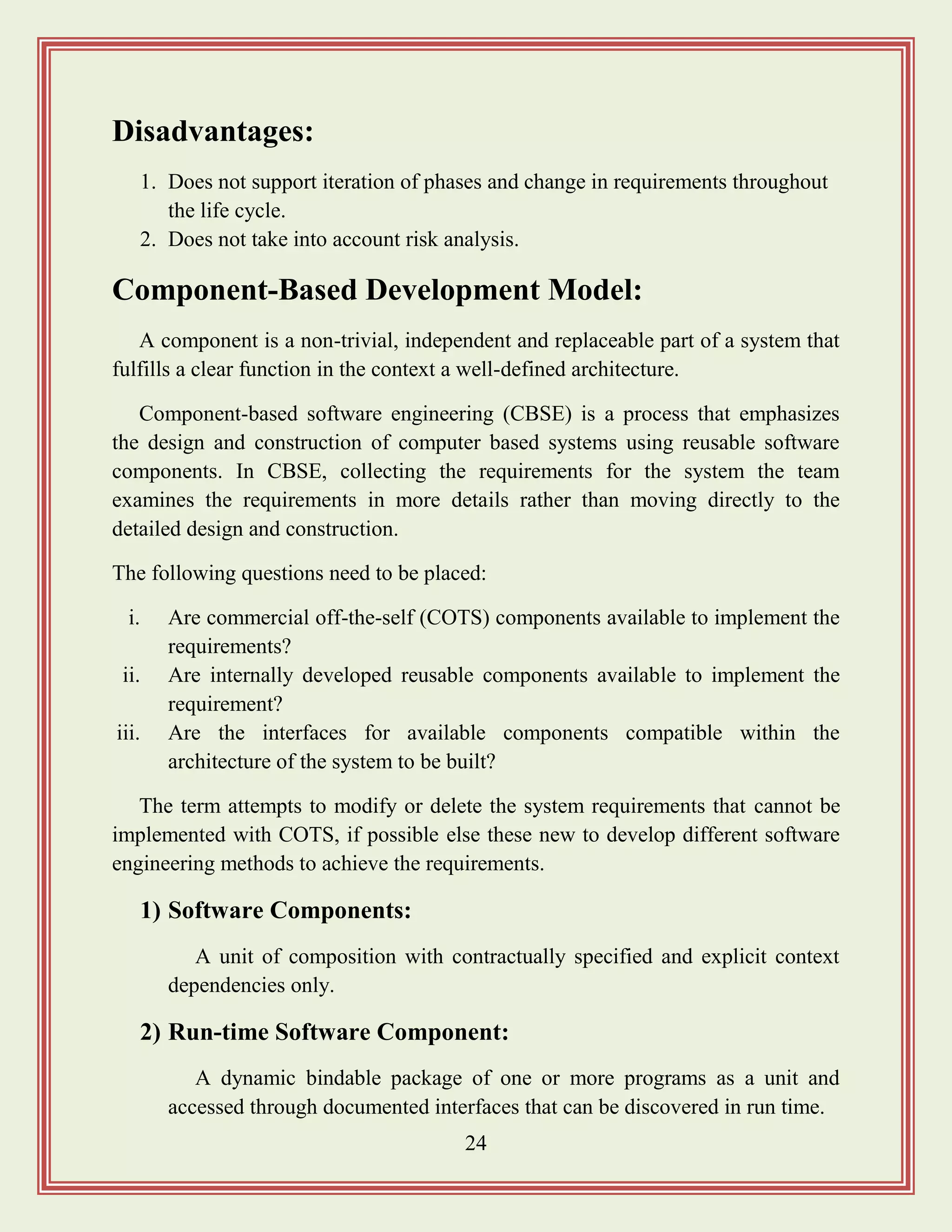
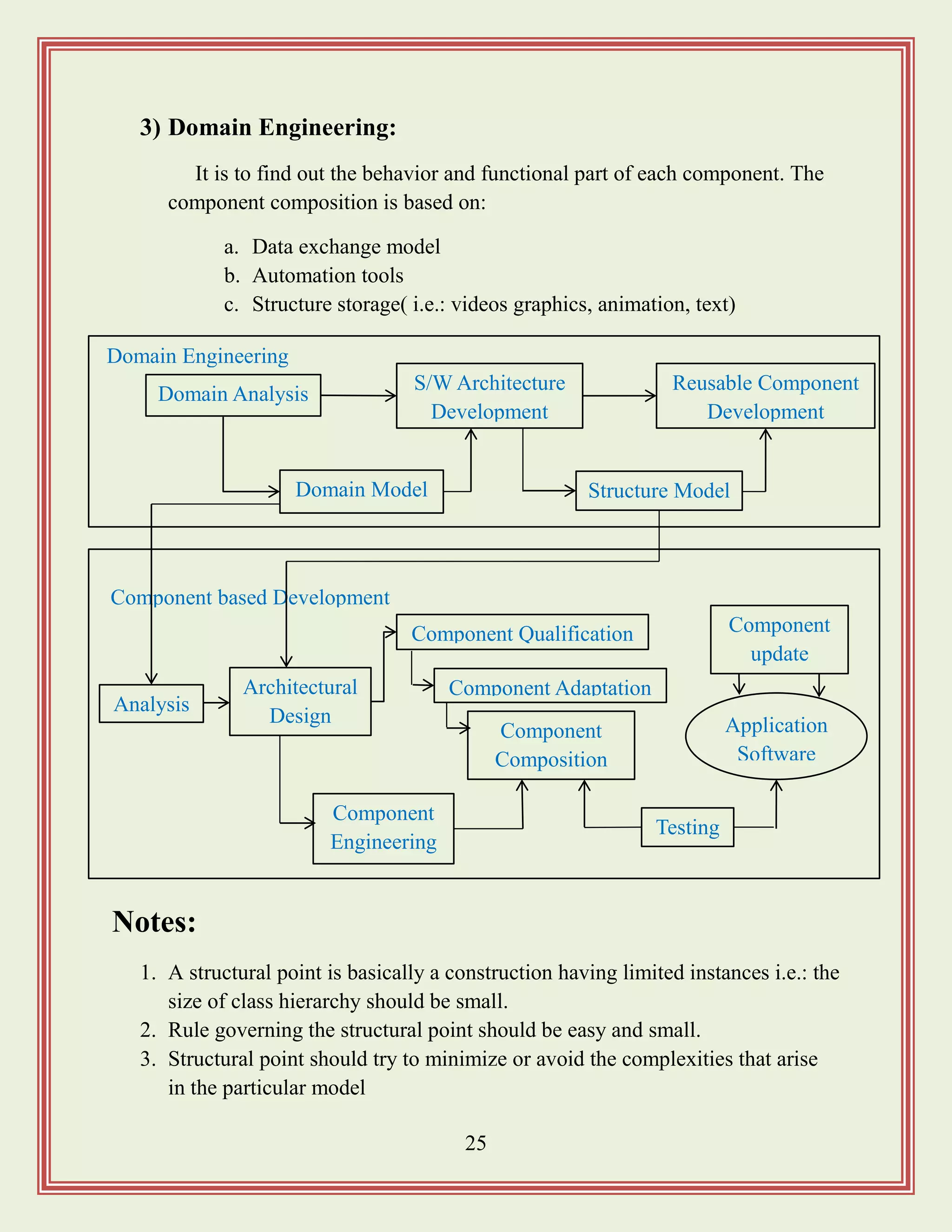

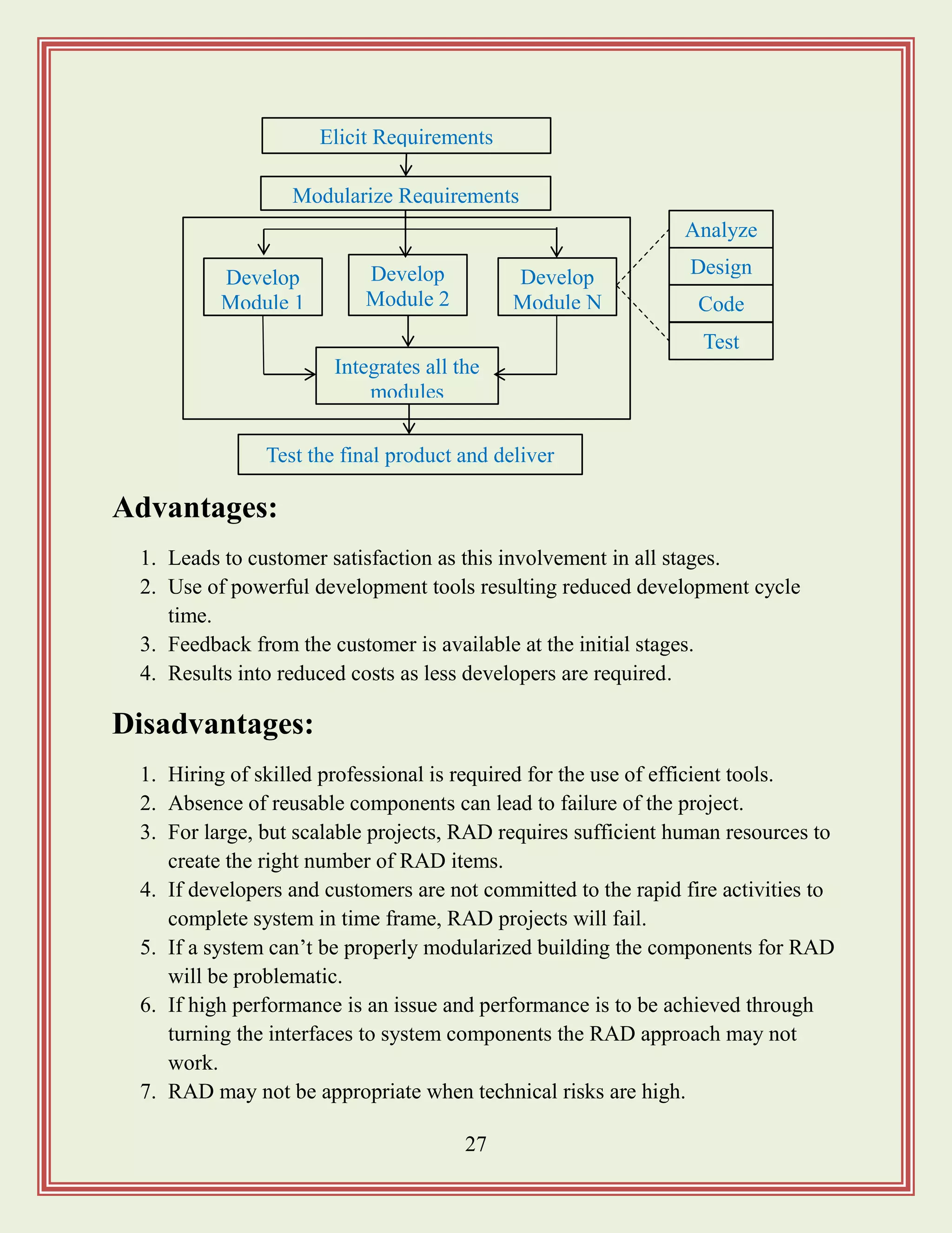
![35
Project planning:
It consists of essential activities. i.e.:
1. Estimating some basic attributes of the project
a. Cost: how much will it cost to develop the project
b. Duration: how long will it take to complete the development?
c. Effort: how much effort would be required?
d. The effectiveness of the subsequent planning activities is based on
the accuracy of these estimations.
2. Scheduling manpower and other resources
3. Staff organization and staffing plans
4. Risk identification, analysis and abatement planning.
5. Miscellaneous plans such as quality assurance plan, configuration
management plan etc.
The Software Project Management Plan (SPMP)
document:
After completion of project planning, project manager, document the result of
the planning phase on software project management plan (SPMP) documents. It
includes the following items.
Effort Estimation Cost Estimation
Size Estimation
Duration
Estimation
Project
Staffing
Scheduling
[Precedence ordering among planning activities]](https://image.slidesharecdn.com/softwareengineeringstudymaterials-171005111336/75/Software-engineering-study-materials-36-2048.jpg)

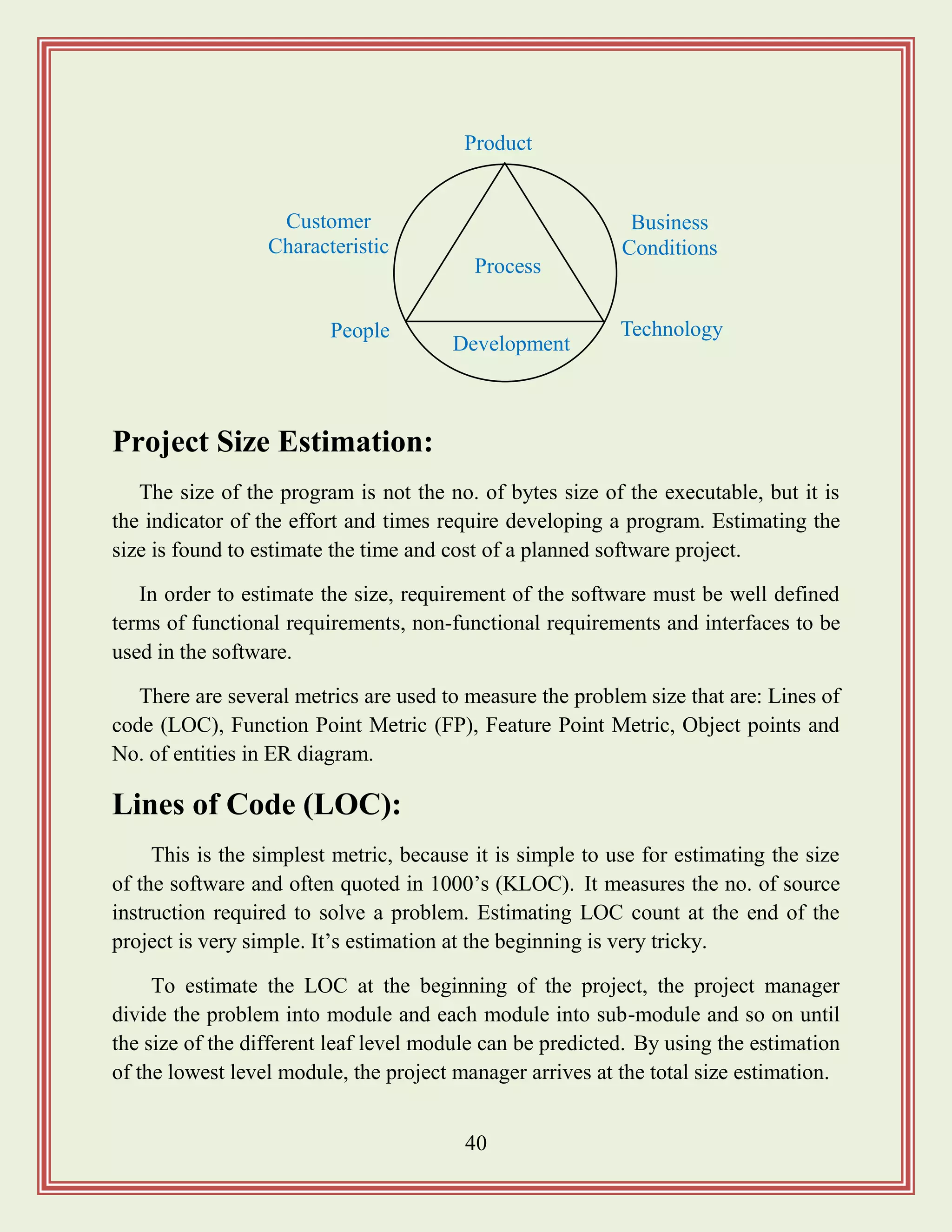
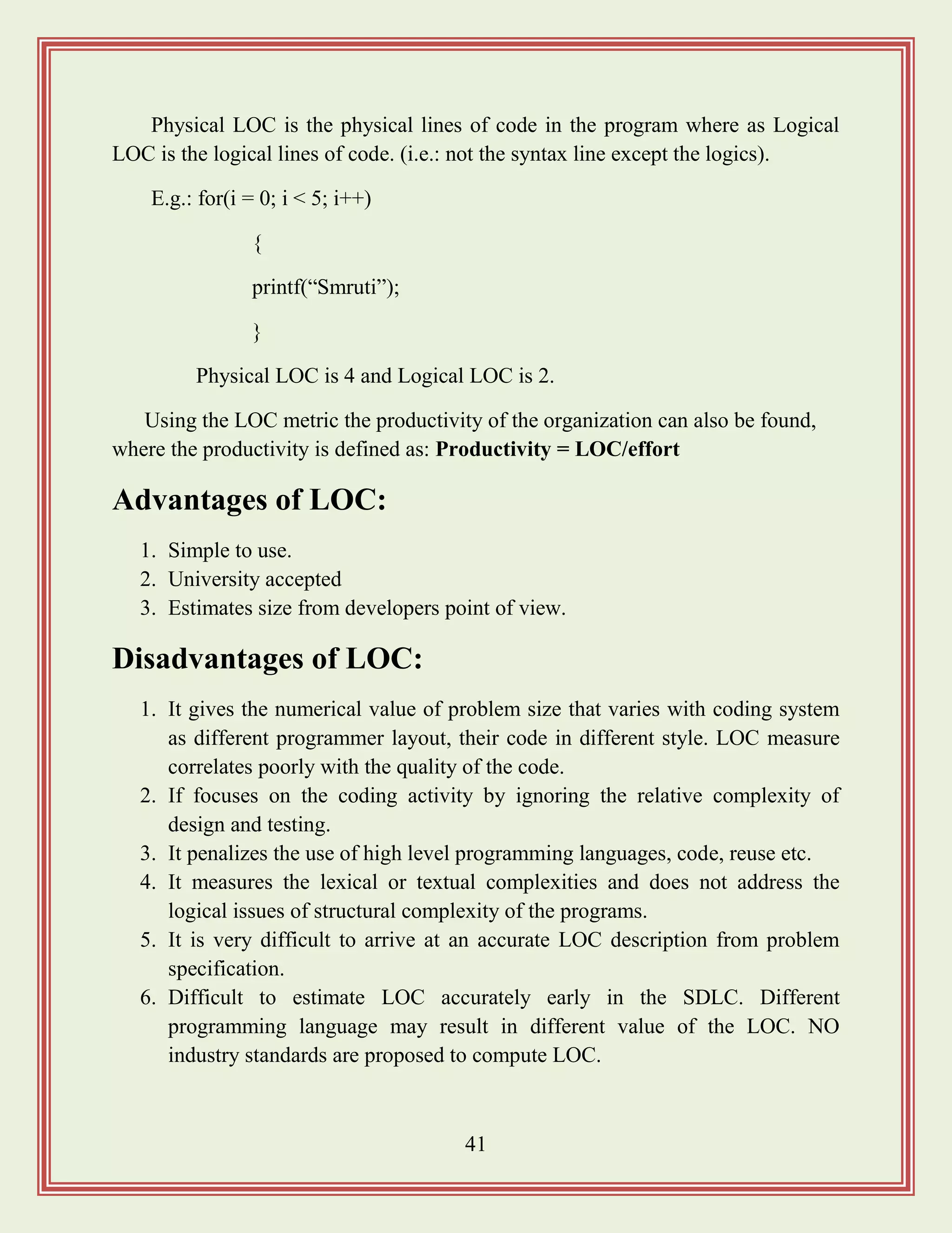
![42
Function Point Metric:
This overcomes from some of the shortcoming of LOC metric. It can be used to
estimate the size of the software directly from the problem specification.
The size of the product is directly dependent on the number and type of
different function it perform. In addition to this, it also depends on the no. of files
and no. of interfaces.
It computes the size of the software product using 5 different characteristics of
the product. The function point of given software is the weighted sum of the
following 5 items. That is: no. of inputs, no. of outputs, no. of inquiries, no. of files
and no. of interfaces. So the formula is:
Size of problem in FP‟s (unadjusted FP [UFP]) =
(No. of input) * 4 + (No. of output) * 5 + (No. of inquiries) * 4 + (No. of file) *
10 + (No. of interfaces) * 10.
Then the Technical Complexity Factor (TCF) is computed, measured by 14
other factors, such as high transaction rate, throughout, response time etc. Each of
the 14 factors is assigned a value 0 – 6. The resulting numbers are summed to give
the total degree of interfluence (DI) that vary from 0 – 70.
TCF = 0.65 + 0.01 * DI
FP = UFP * TCF
Advantages of Function Point Metric:
1. It is not restricted to code.
2. The language is independent.
3. The necessary data is available early in a project. Thus only a detailed
specification is required.
4. It is more accurate than LOC.
5. It can be used to easily estimate the size of the software product directly
from problem specification.](https://image.slidesharecdn.com/softwareengineeringstudymaterials-171005111336/75/Software-engineering-study-materials-43-2048.jpg)
![43
Drawbacks of Function Point Metric:
1. Hard to automate and difficult to compute.
2. Ignores the quality of output.
3. It does not take into account the algorithmic complexity of software.
4. Oriented to traditional data processing application.
5. Subjective counting. i.e.: different people can come up with different
estimate for the same problem.
Feature Point Metric:
A major shortcoming of function point metric is that it does not take into
account the algorithmic complexity of software. To overcome from this the
“feature point metric” is introduced.
Feature point metric incorporates an extra parameter into algorithm complexity.
This parameter ensures that the computed size using the feature point metric
reflects the fact that the more complexity of a function greater the effort required to
develop it and therefore its size should be larger compared to similar functions.
Architectural Design Metrics:
This focuses on characteristics of the program architecture with an emphasis on
the architectural structure and effectiveness of modules or components within the
architecture.
These types of metrics are the black box in the sense that they don‟t require any
knowledge of inner workings of a particular software component. The complexity
measures are: Structural Complexity, Data Complexity and System Complexity.
For hierarchical architecture (e.g.: call and return), the structural complexity
of a module „i‟ is: S(i) = f2
out(i) [fout(i) = fan-out of i]
Data complexity provides an indication of the complexity in the internal
interface for a module „i‟ and is defined as:
D(i) = V(i)/(fout(i) + 1) [V(i) = no. of input and output variables in „i‟]](https://image.slidesharecdn.com/softwareengineeringstudymaterials-171005111336/75/Software-engineering-study-materials-44-2048.jpg)
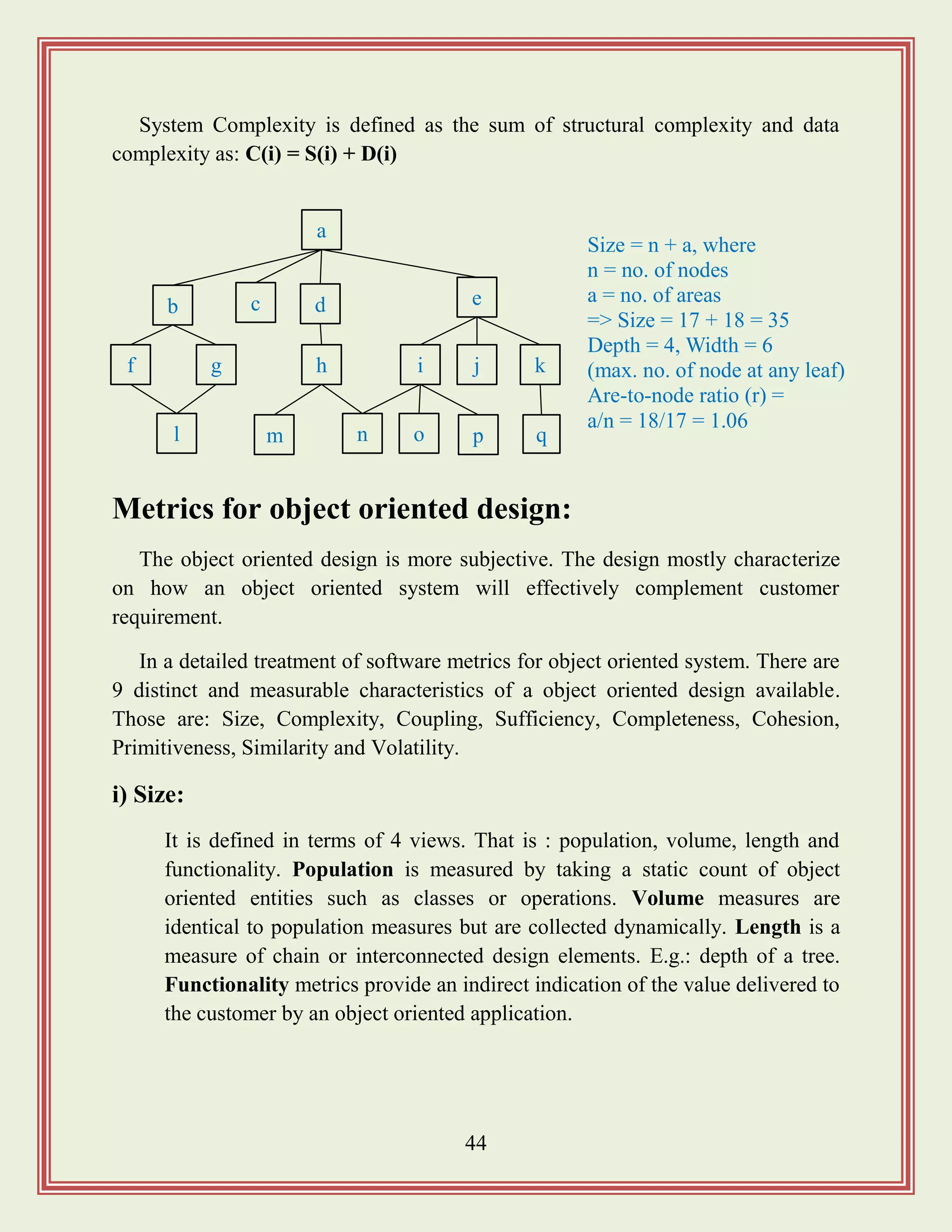

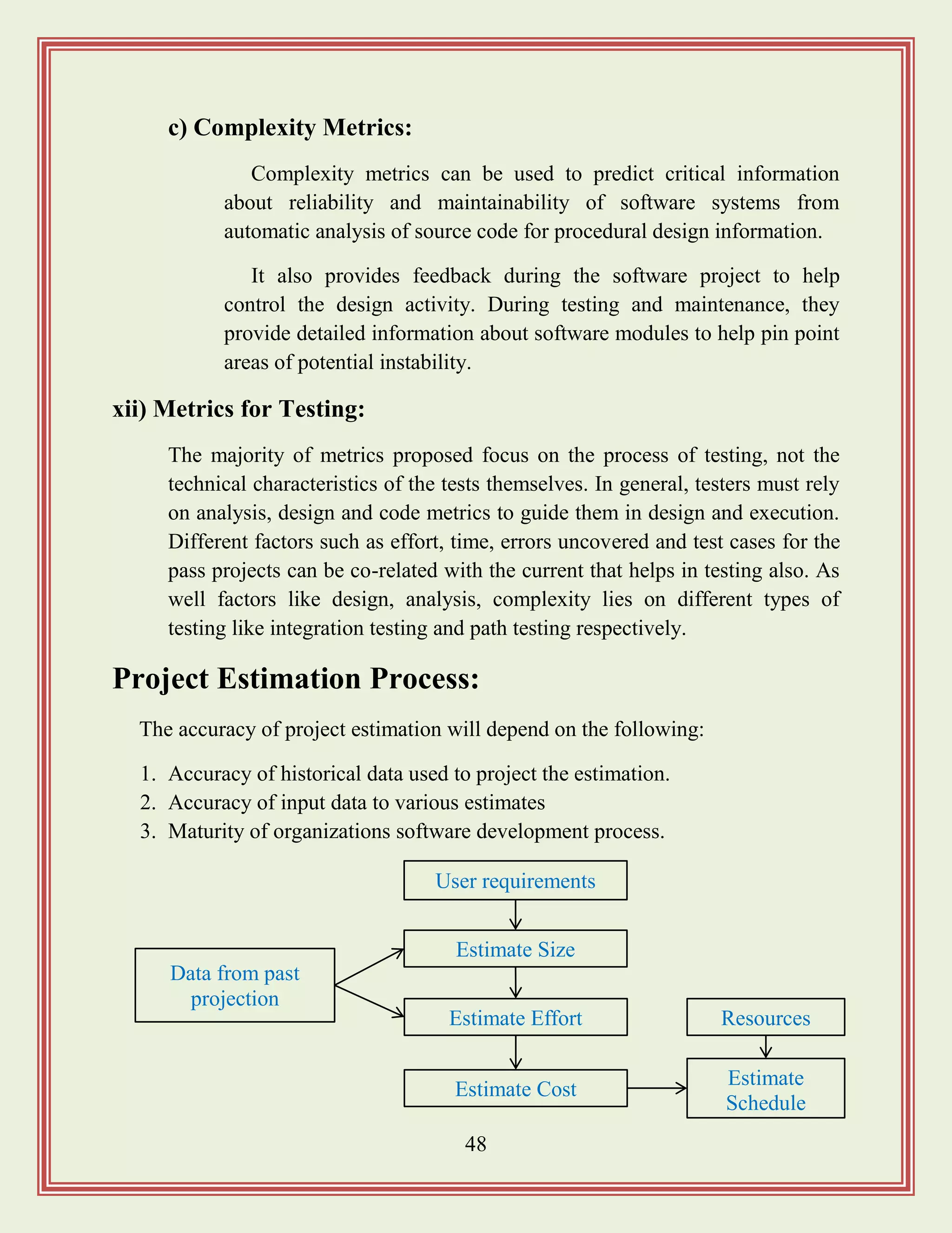
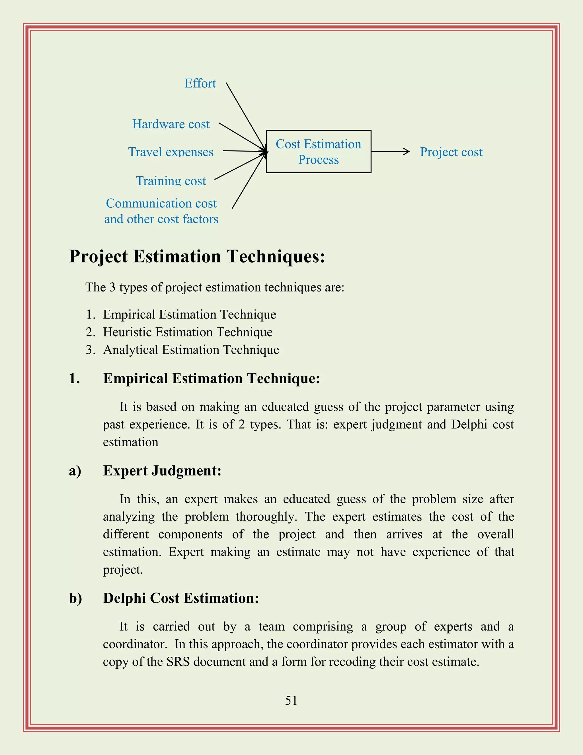
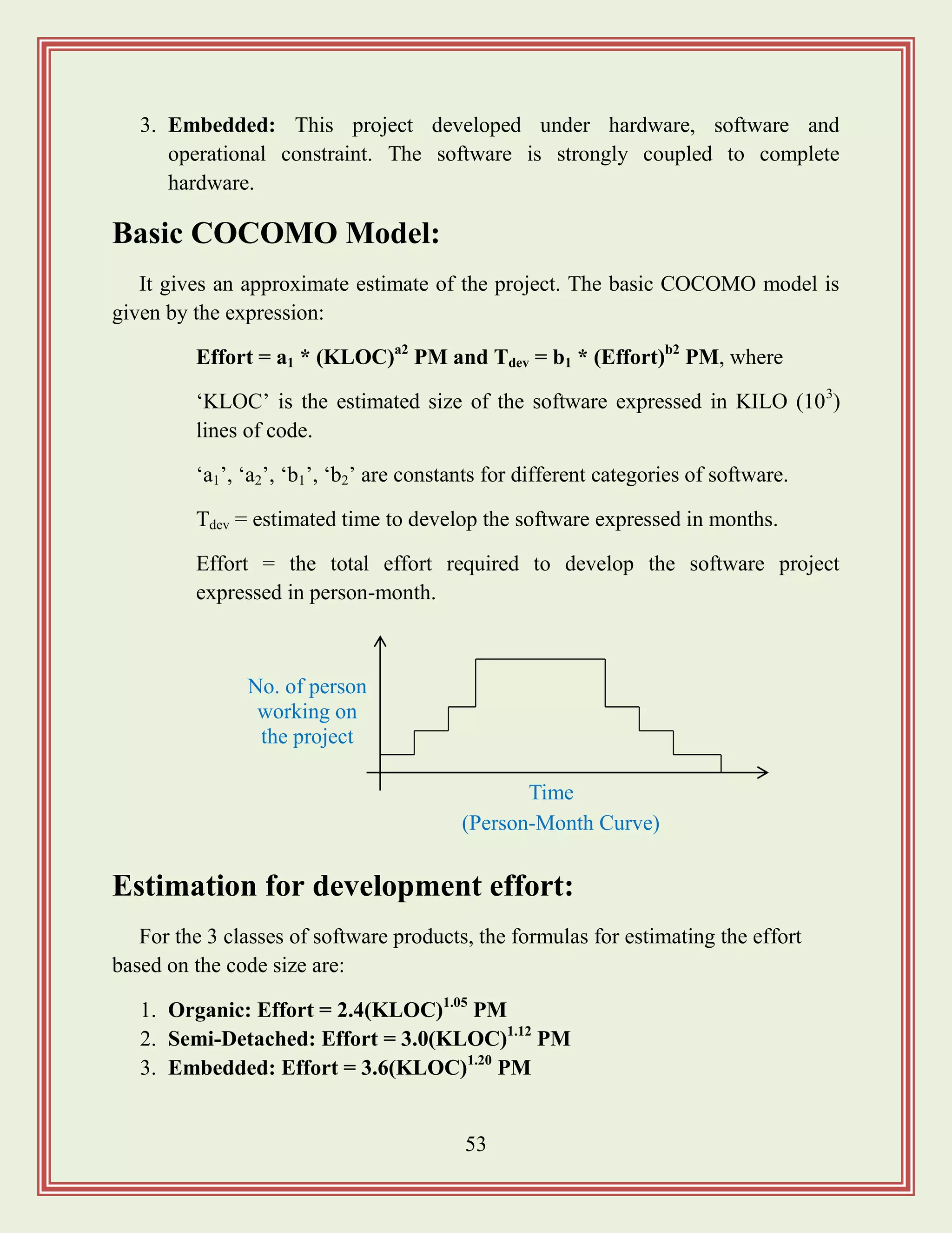
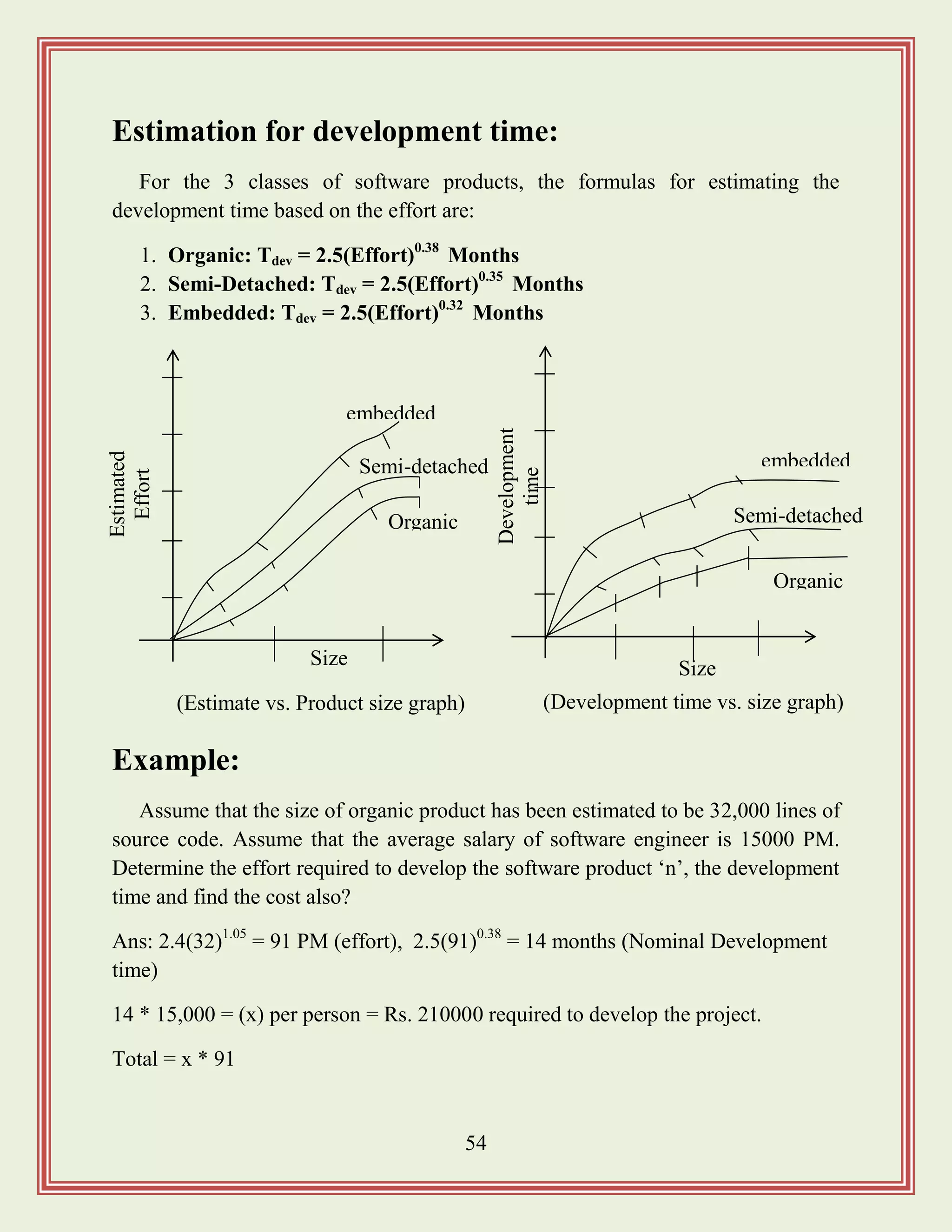
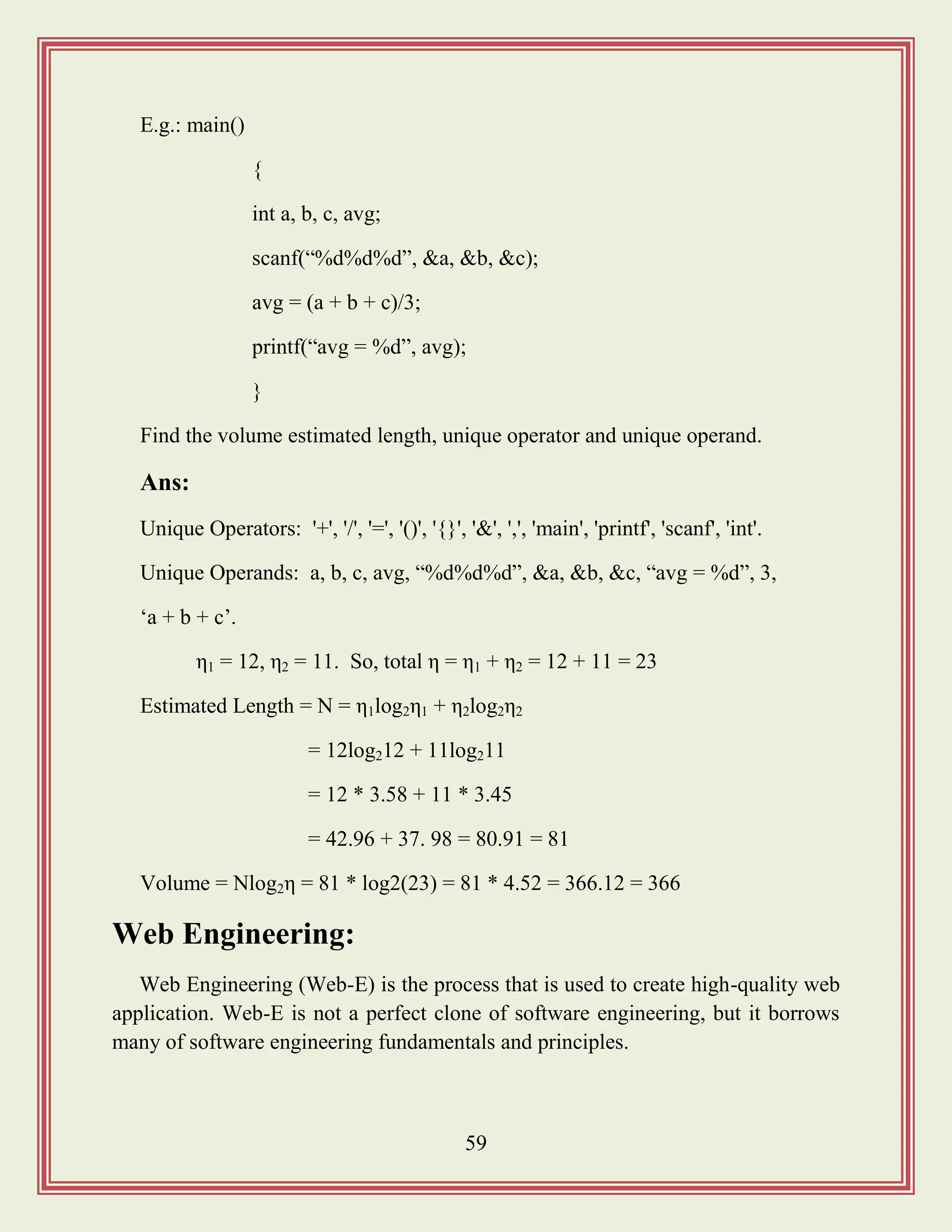

![63
2) Activity Networks:
WBS representation of a project is transformed into an activity network
by representing the activities identified in WBS along with their
interdependencies.
An activity network shows the different activities making up a project,
their estimated durations, and interdependencies. Managers can estimate the
time durations for the different tasks in several ways. One possibility is that
they can empirically assign durations to different tasks.
MIS
Application
Requirement
Analysis
DocumentDesign Code
Database
Part
Test
GUI
Part
GUI
Part
Database
Part
[Work Breakdown Structure for MIS (management information system) Software]
Design database
part 45
Specification 15
Finish 0
Design GUI
part 30
Code GUI part
45
Write user manual 60
Integrate and Test 120
[Activity network representation of the MIS problem ]
Code database
part 105](https://image.slidesharecdn.com/softwareengineeringstudymaterials-171005111336/75/Software-engineering-study-materials-64-2048.jpg)
![65
length of time each task is estimated to take. The white part shows the slack
time, which is the latest time by which a task must be finished.
5) PERT Charts:
PERT (Project Evaluation and Review Technique) charts consist of a
network of boxes and arrows. The boxes represent activities and the arrows
represent task dependencies.
PERT chart represents the statistical variations in the project estimates
assuming a normal distribution. Thus in PERT chart instead of making a
single estimate for each task, pessimistic, likely and optimistic estimates are
also made.
The boxes of PERT charts are usually annotated with the pessimistic,
likely and optimistic estimates for every task.
All possible completion times between the minimum and maximum
durations for every task have to be considered, there is not one but many
Jan 1
Design database
Part
Design GUI
Part
Integrate and
Test
[Gantt chart representation of the MIS problem]
Code database
part
Specification
Write user manual
Jan 15 July 15Apr 15 Nov 15Mar 15](https://image.slidesharecdn.com/softwareengineeringstudymaterials-171005111336/75/Software-engineering-study-materials-66-2048.jpg)
![66
critical paths, depending on the permutations of the estimates for each task.
This makes critical path analysis in PERT charts very complex.
A critical path in a PERT chart is shown by using thicker arrows. PERT
charts are a more sophisticated form of activity chart. In activity diagram
only the estimated task durations are represented.
Gantt chart representation of a projected schedule is helpful in planning
the utilization of resources, while a PERT chart is useful for monitoring the
timely progress of activities. It is easier to identify parallel activities in a
project using a PERT chart.
Project Monitoring and Control:
Once the project gets under-away, the project manager has to monitor the
project continuously to ensure that it progresses as per the plan. The project
manager designates certain key events such as completion of some important
activities as milestones.
Design database part
40, 45, 60
Specification
12, 15, 20
Finish 0
Design GUI part
24, 30, 38
Code GUI part
38, 45, 52
Write user manual
50, 60, 70
Integrate and Test
100, 120, 140
[PERT chart representation of the MIS problem ]
Code database part
95, 105, 120](https://image.slidesharecdn.com/softwareengineeringstudymaterials-171005111336/75/Software-engineering-study-materials-67-2048.jpg)
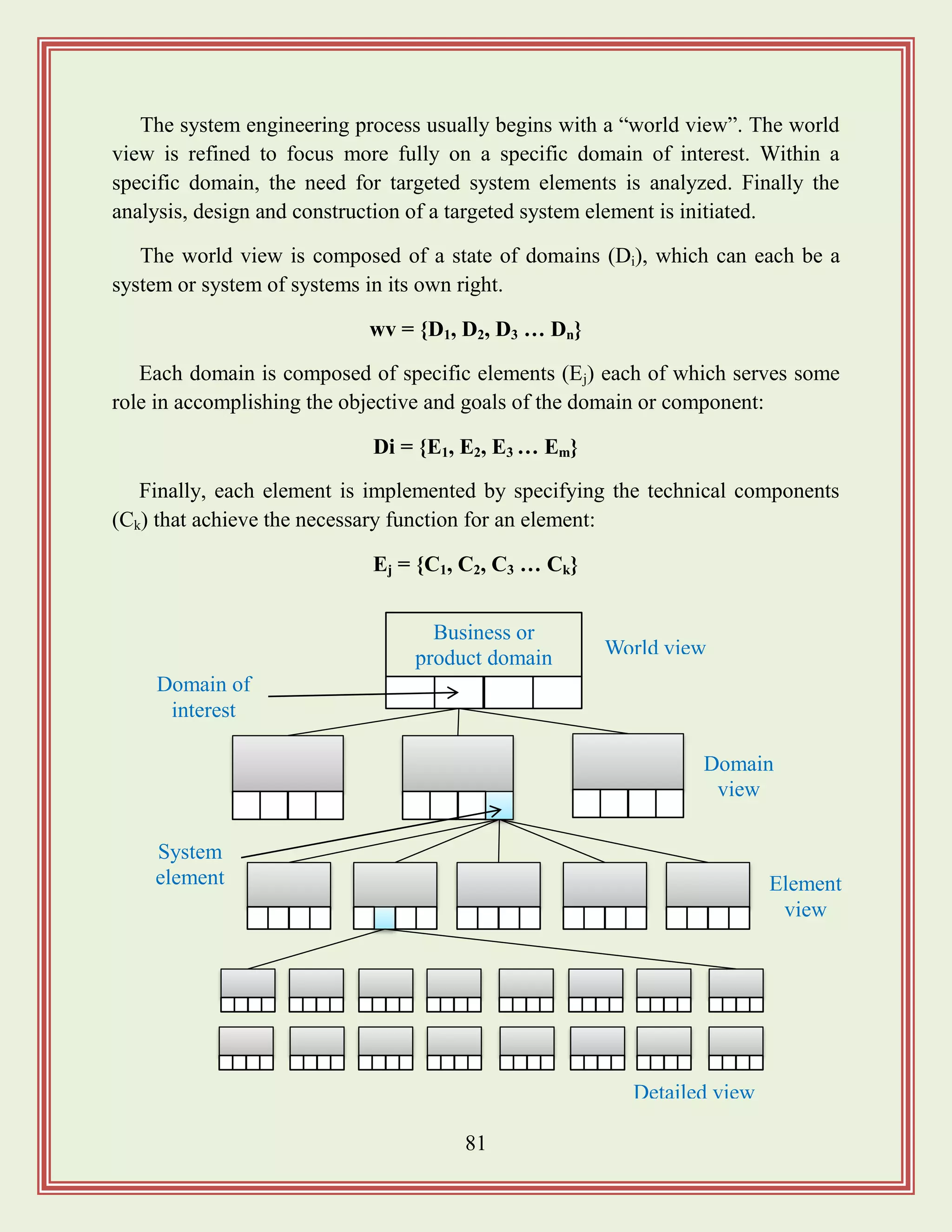
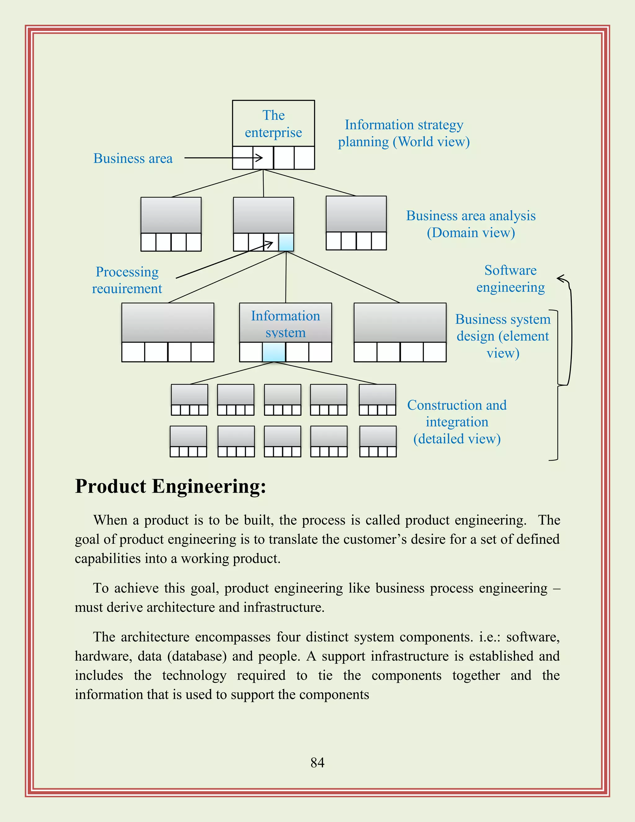
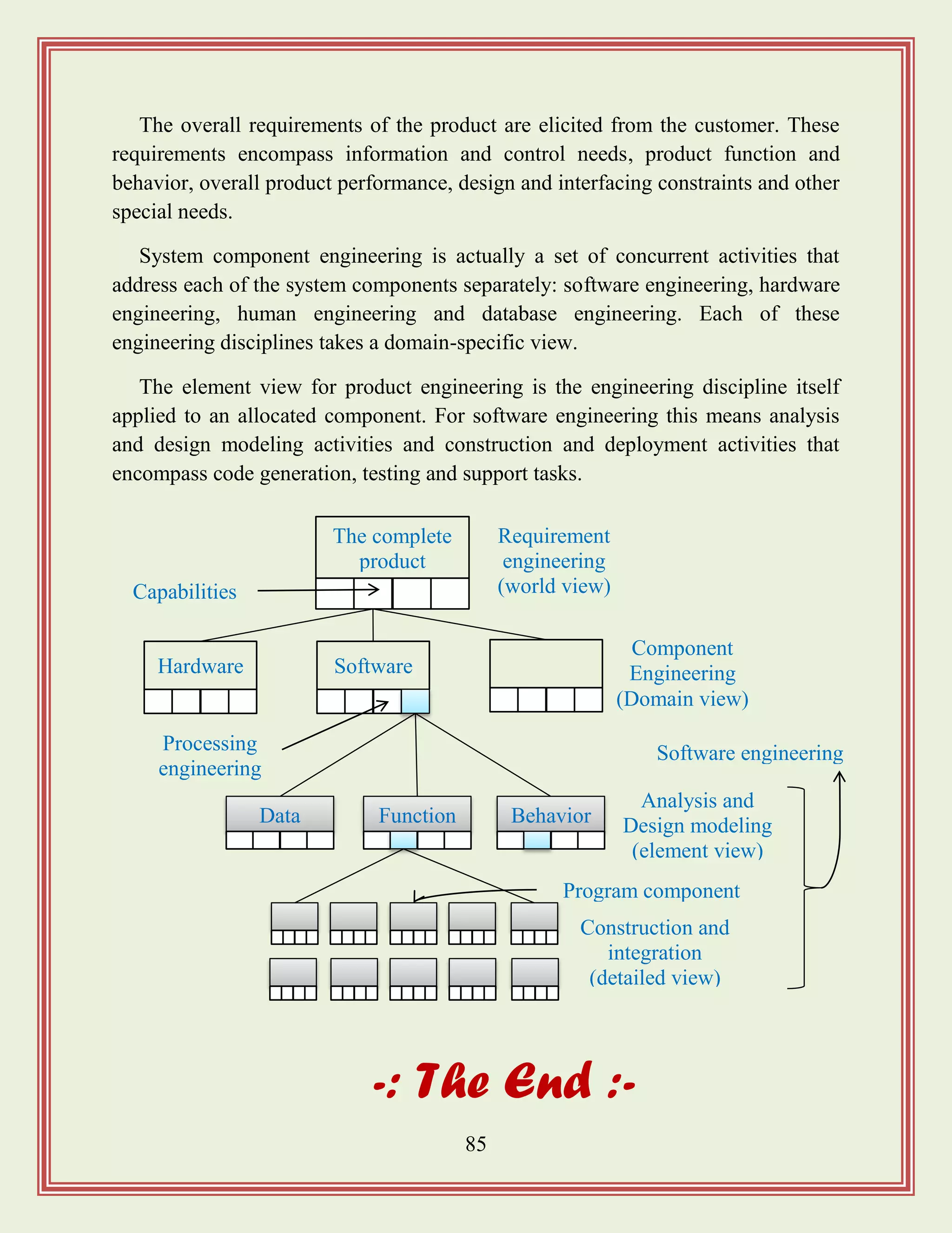

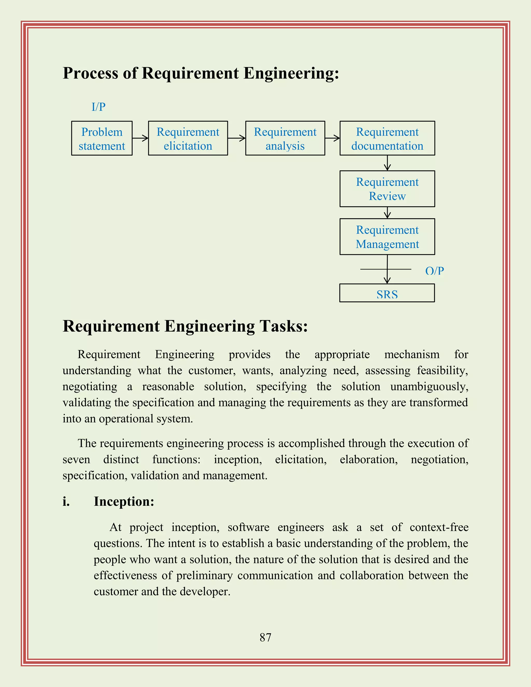
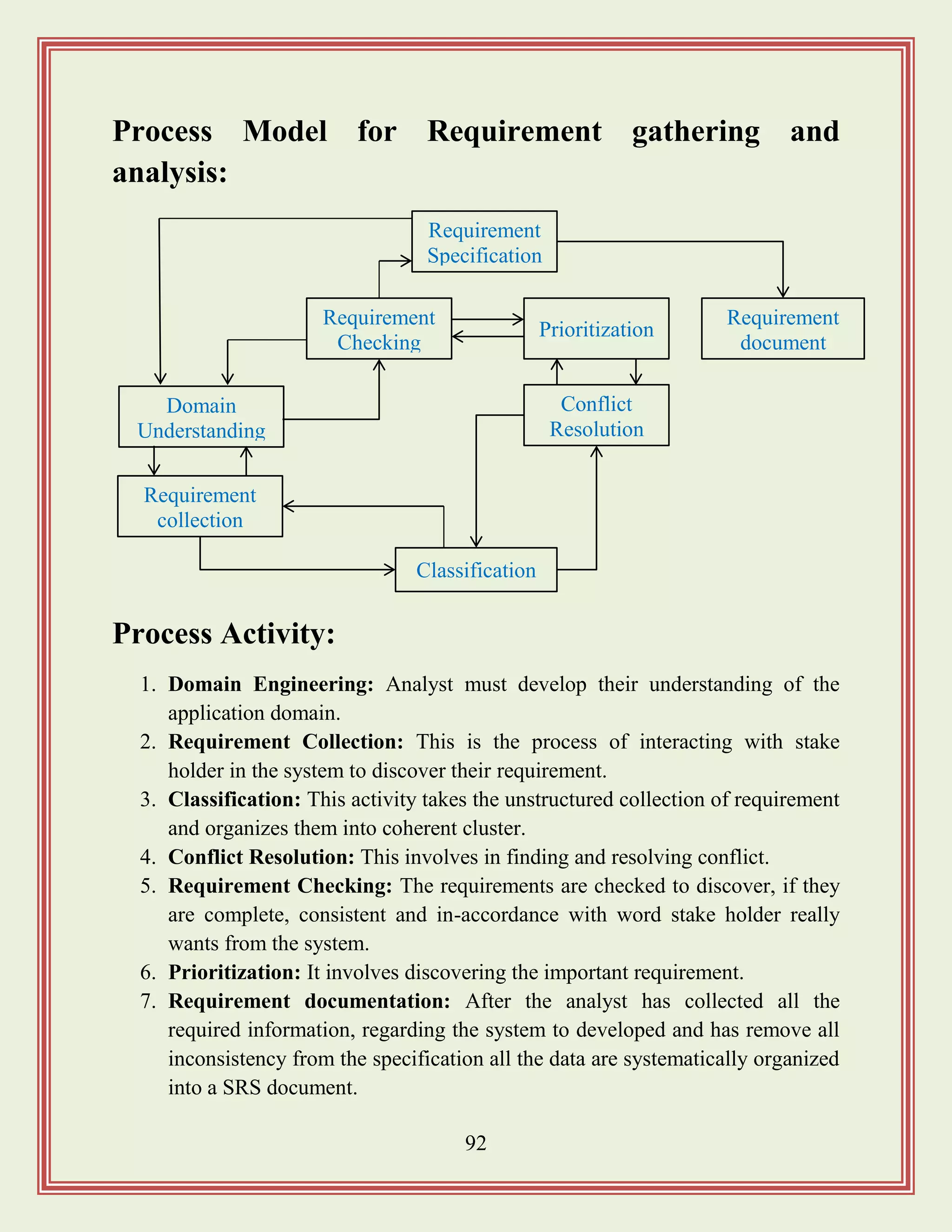
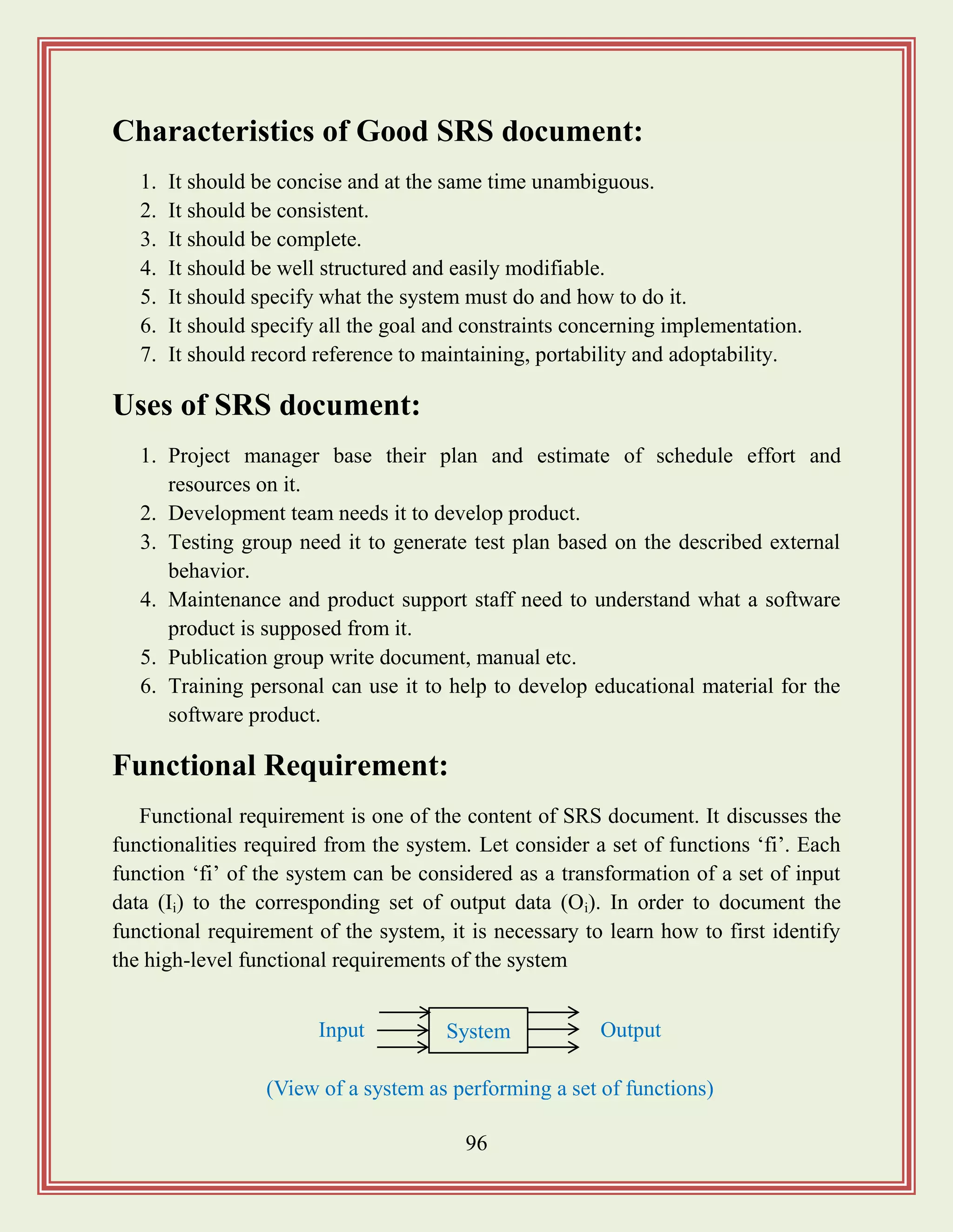
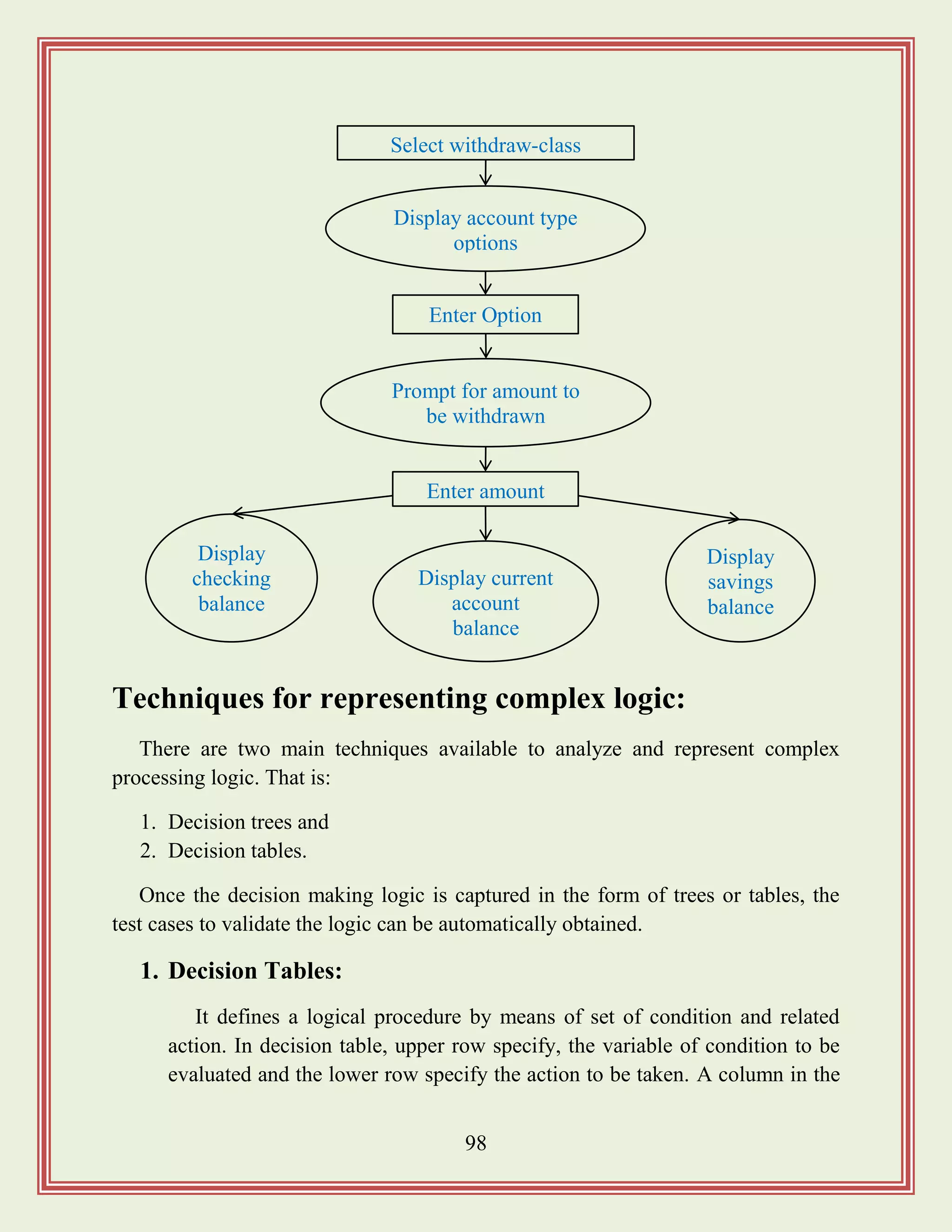
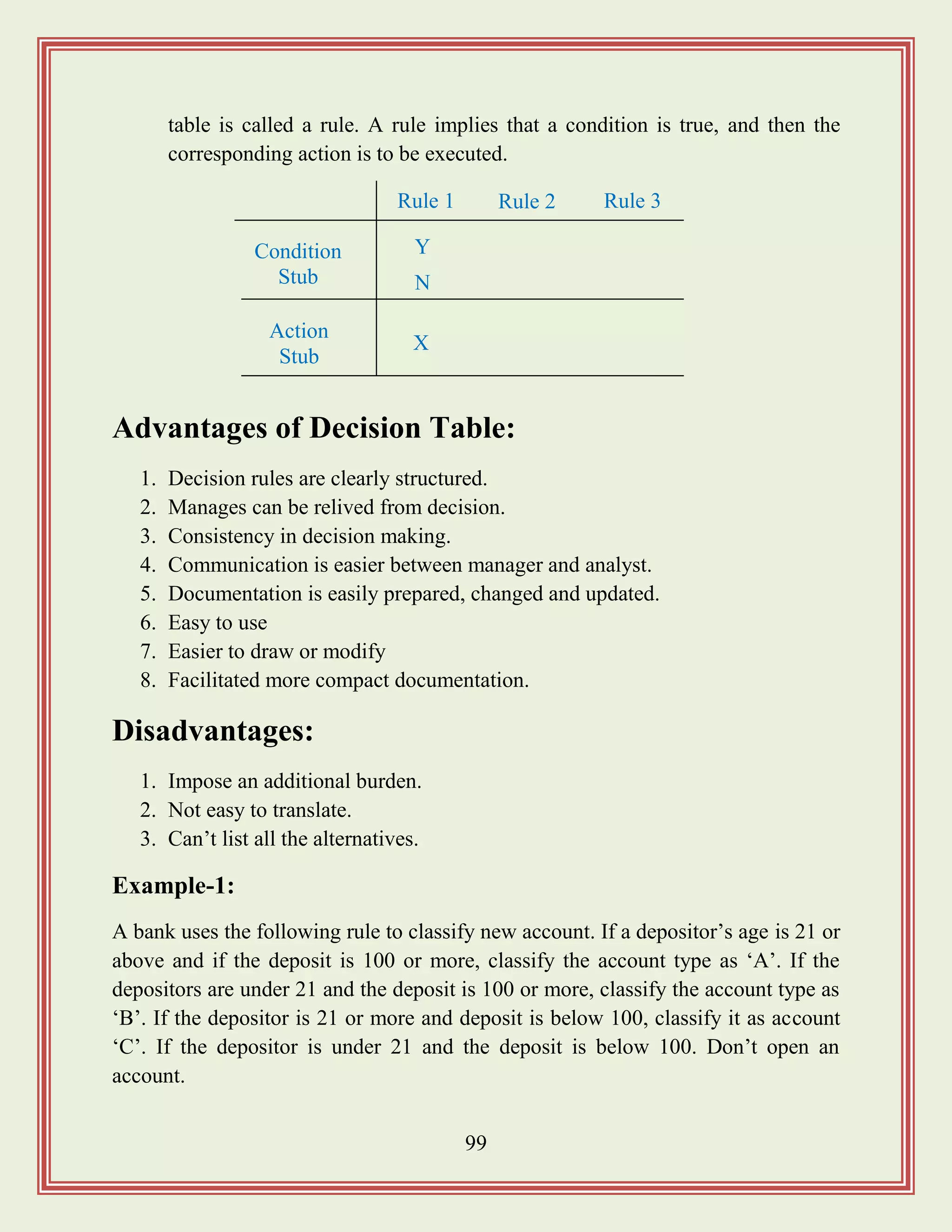
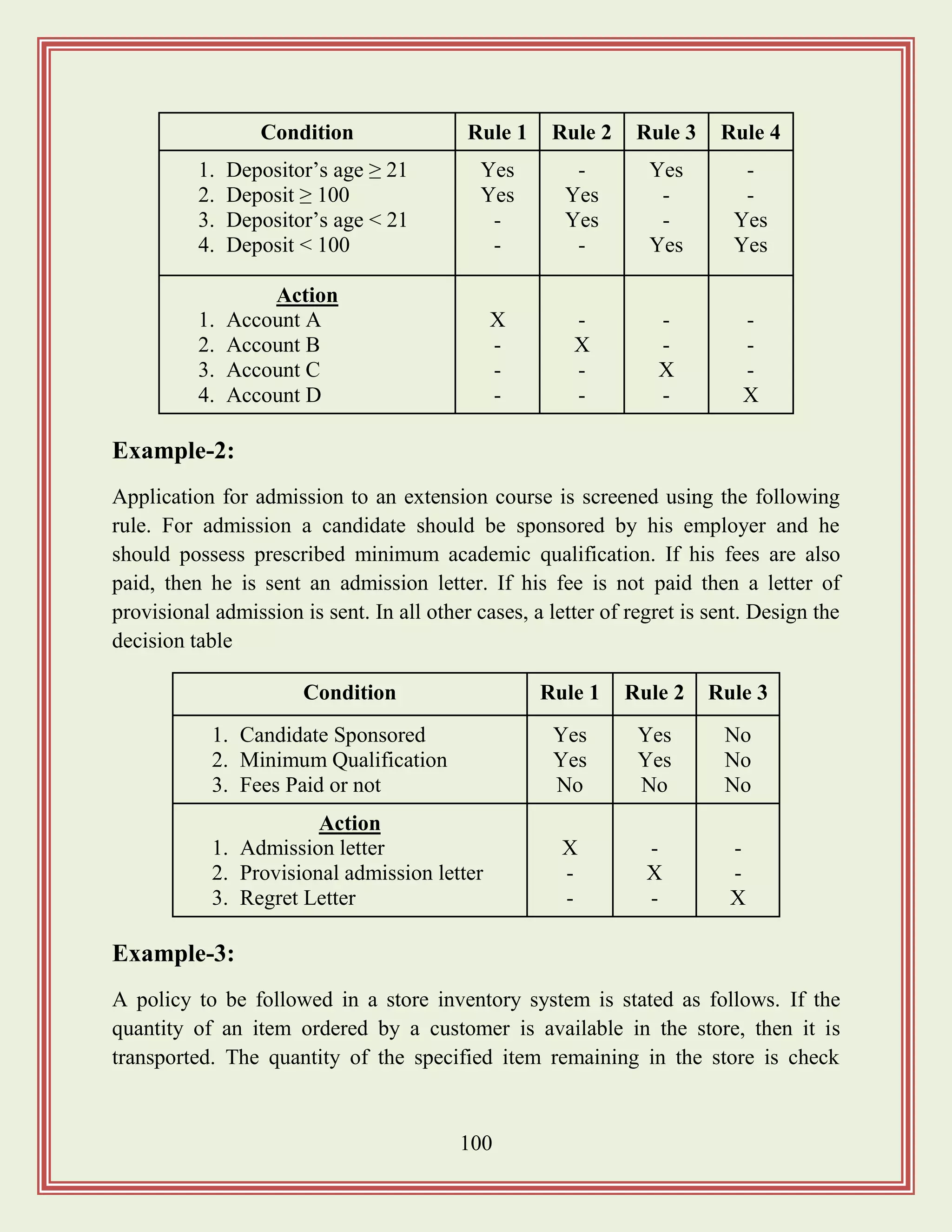
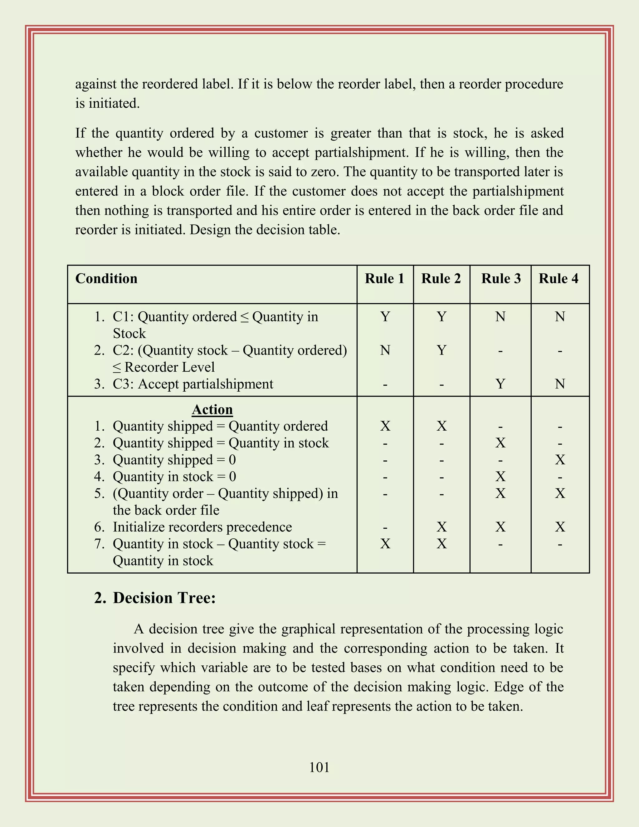
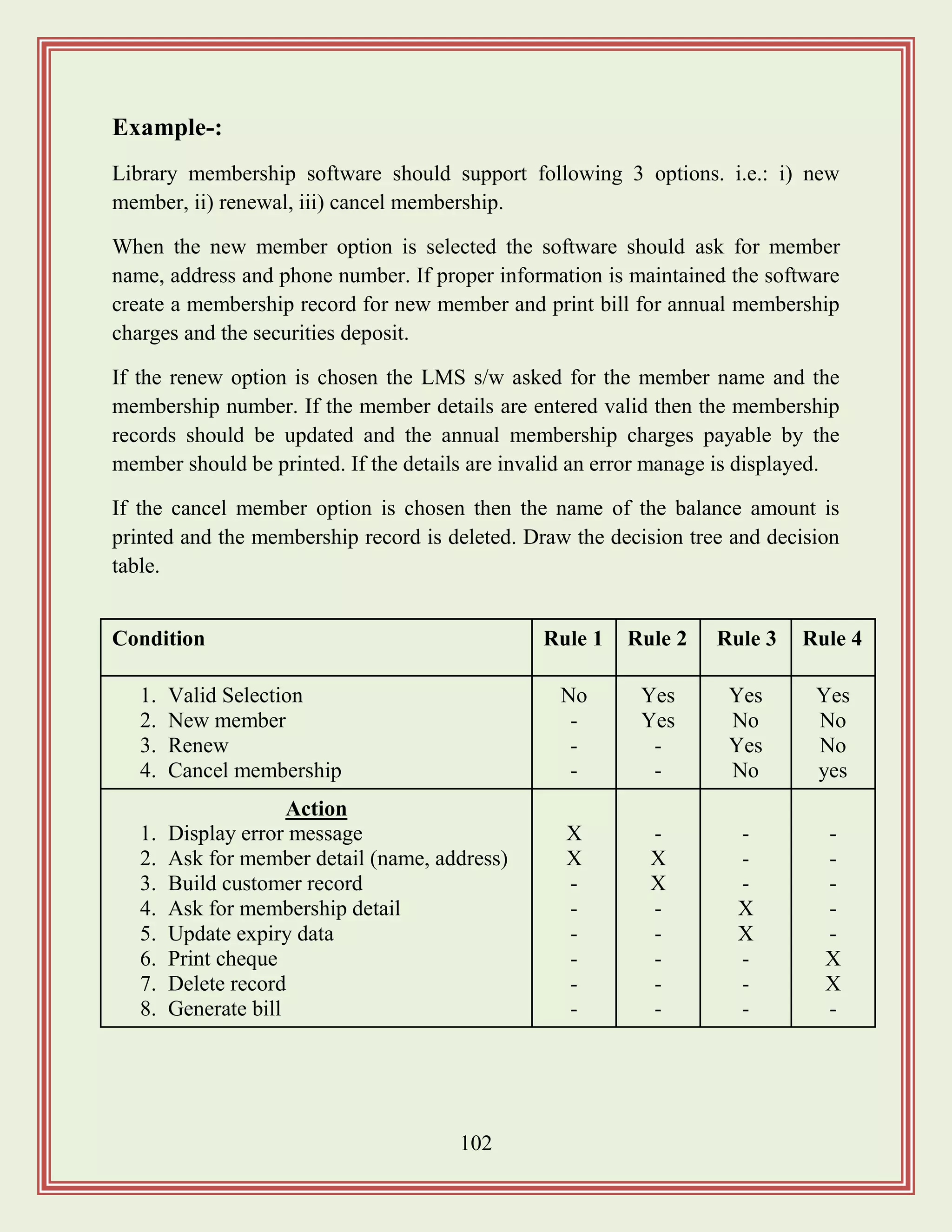
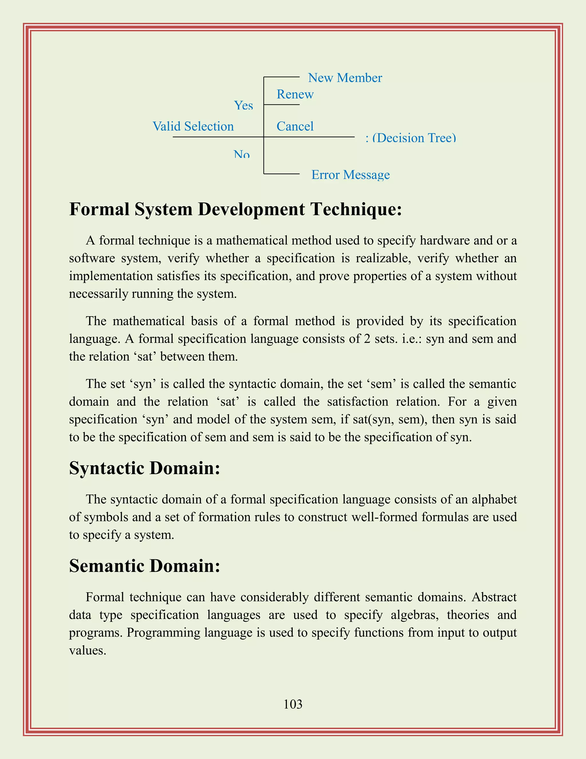


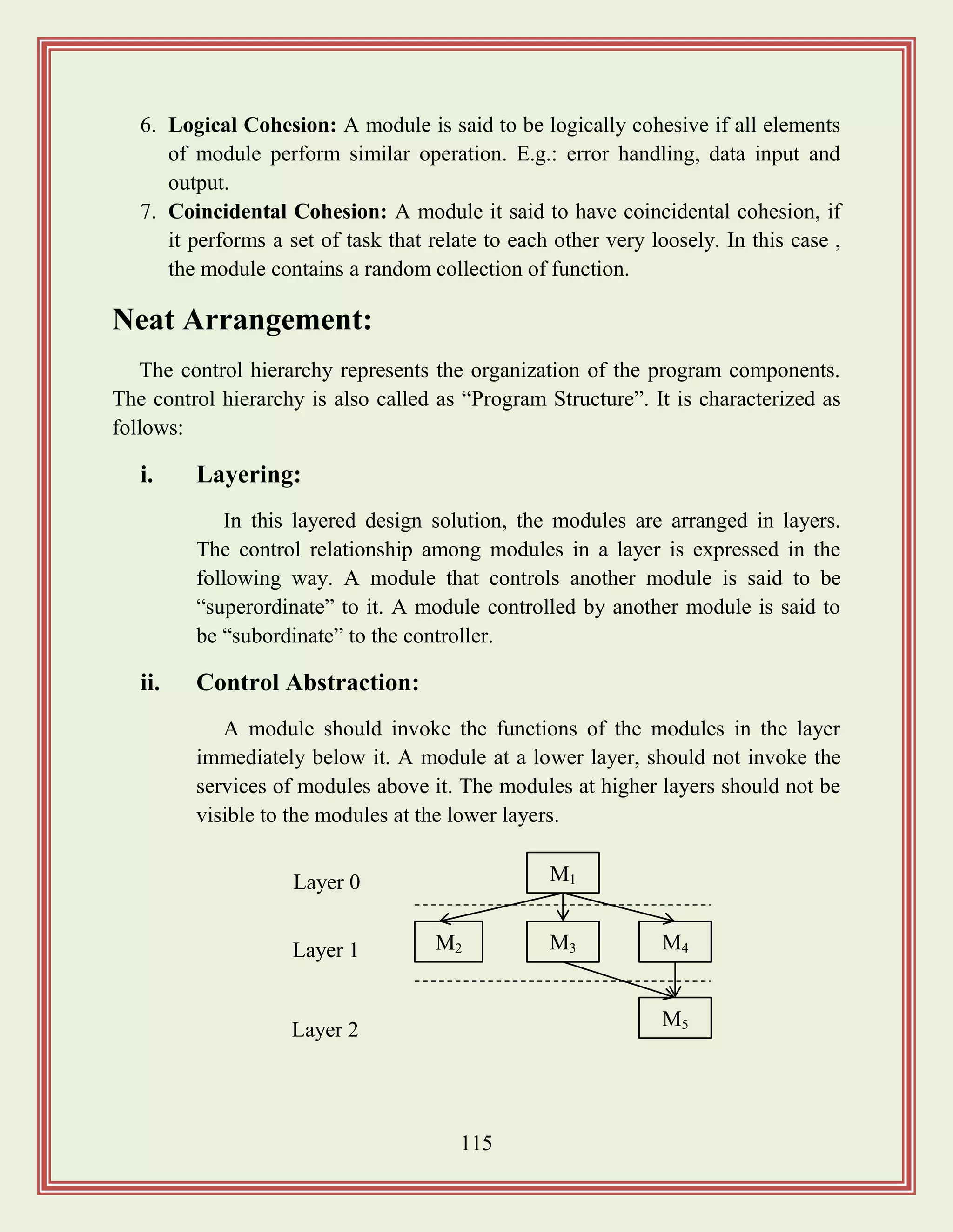

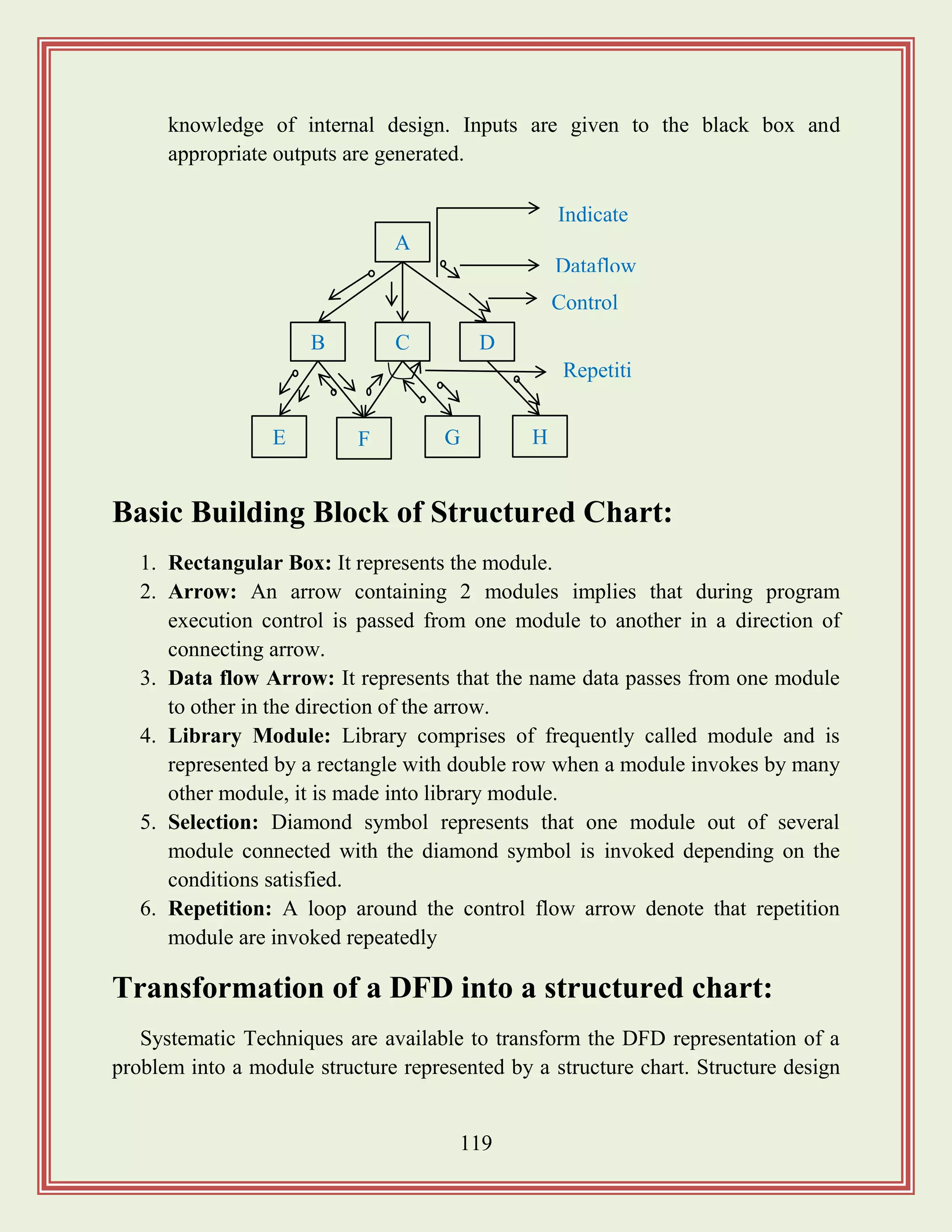
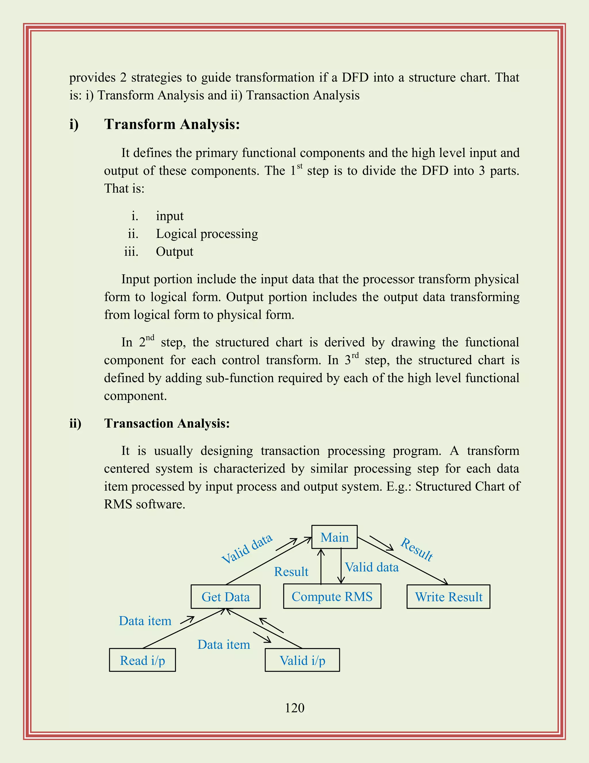
![122
Data Dictionary:
It lists all the data item appearing in the DFD. i.e.: a data dictionary contains all
data flow and the contents of all data store appearing on the DFD.
A data dictionary lists the purpose of all data item and the definition of all
composite data item in term of their component data item. E.g.: gross pay of
employee. A data dictionary is important in the software development process
because of the following reason.
It lists standard terminology for all related data for used by engineer working on
a project. It provides the analyst with means to determine the definition of different
data structure in terms of their component element.
Data Definition:
Composite data are defined in terms of primitive data item, using the following
data definition operator. Those are:
1. „+‟ operator: It represents the composition of data.
2. [, ,]: It represents the selection. E.g.: [a, b].
3. {}: It represents the iterative data definition. E.g.: {name}, 5:- 5 names are
to be stored.
4. (): The content inside the bracket represent the optional data which may or
may not appear.
5. =: Equivalence
6. /* */: Comment
Balancing DFDs:
The data that flow into or out of a bubble must match the dataflow at the next
level of the DFD. This is known as “balancing the DFD”.
i. Numbering of bubbles: The bubble at the context level is assigned the
number zero to indicate that it is zero level DFD. The bubbles at level 1
are numbered as 0.1, 0.2, 0.3 etc. The bubbles at level 2 are numbered as:
0.2.1, 0.2.2, 0.2.3, 0.2.4, 0.2.5 etc.](https://image.slidesharecdn.com/softwareengineeringstudymaterials-171005111336/75/Software-engineering-study-materials-123-2048.jpg)
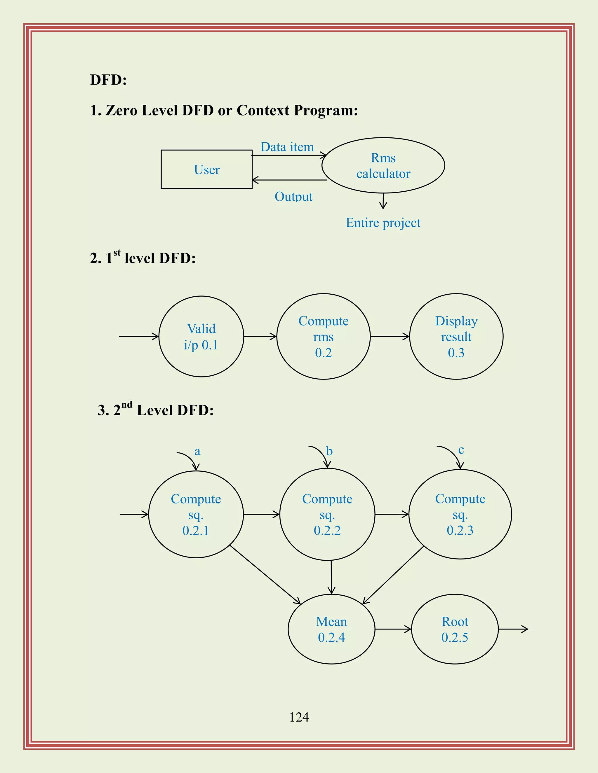
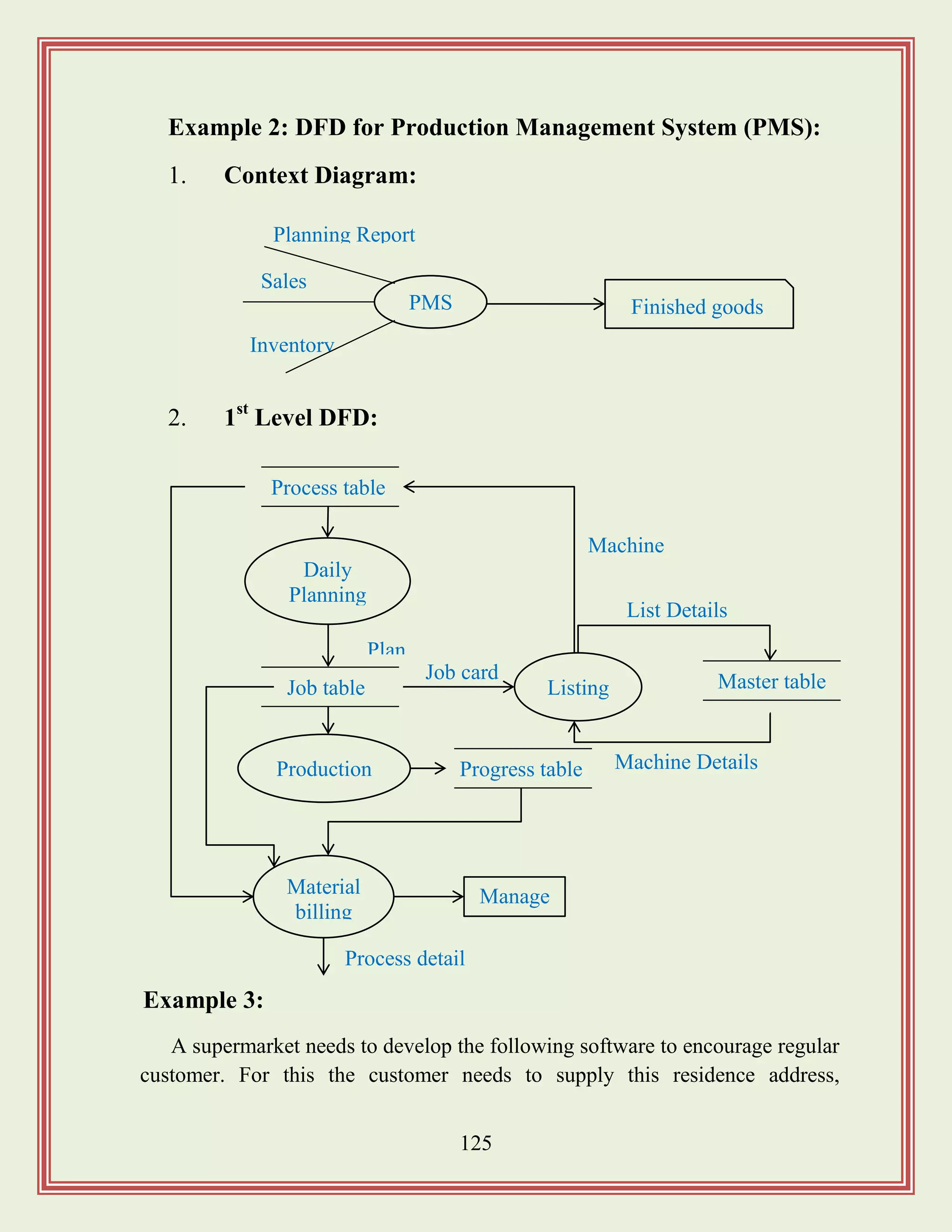
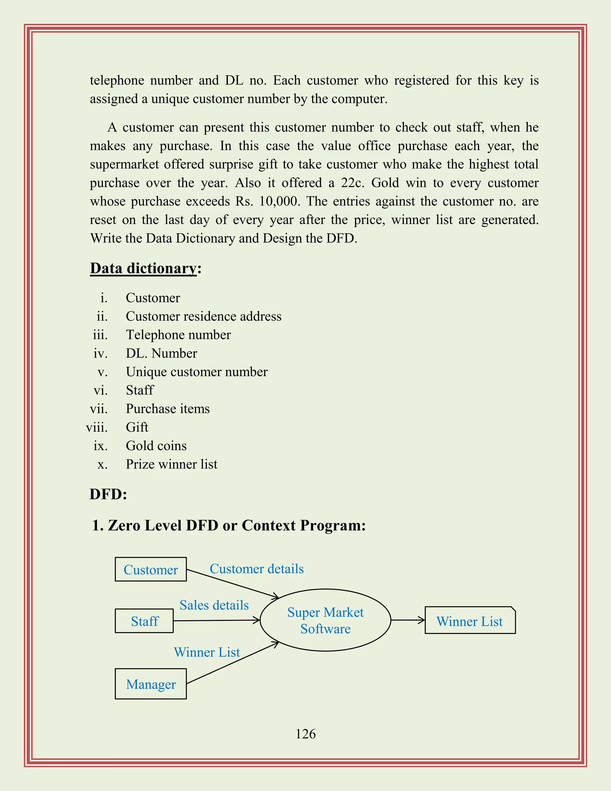
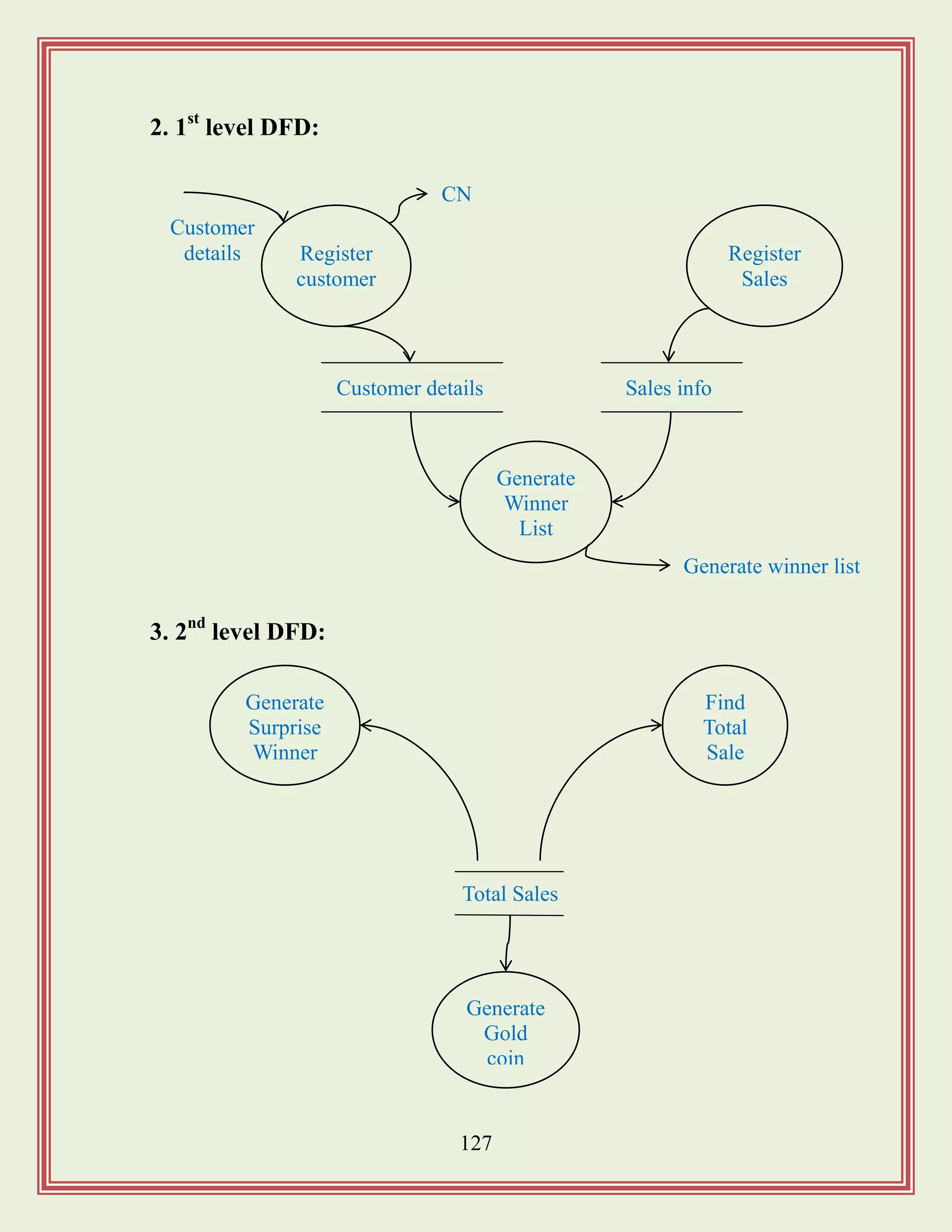
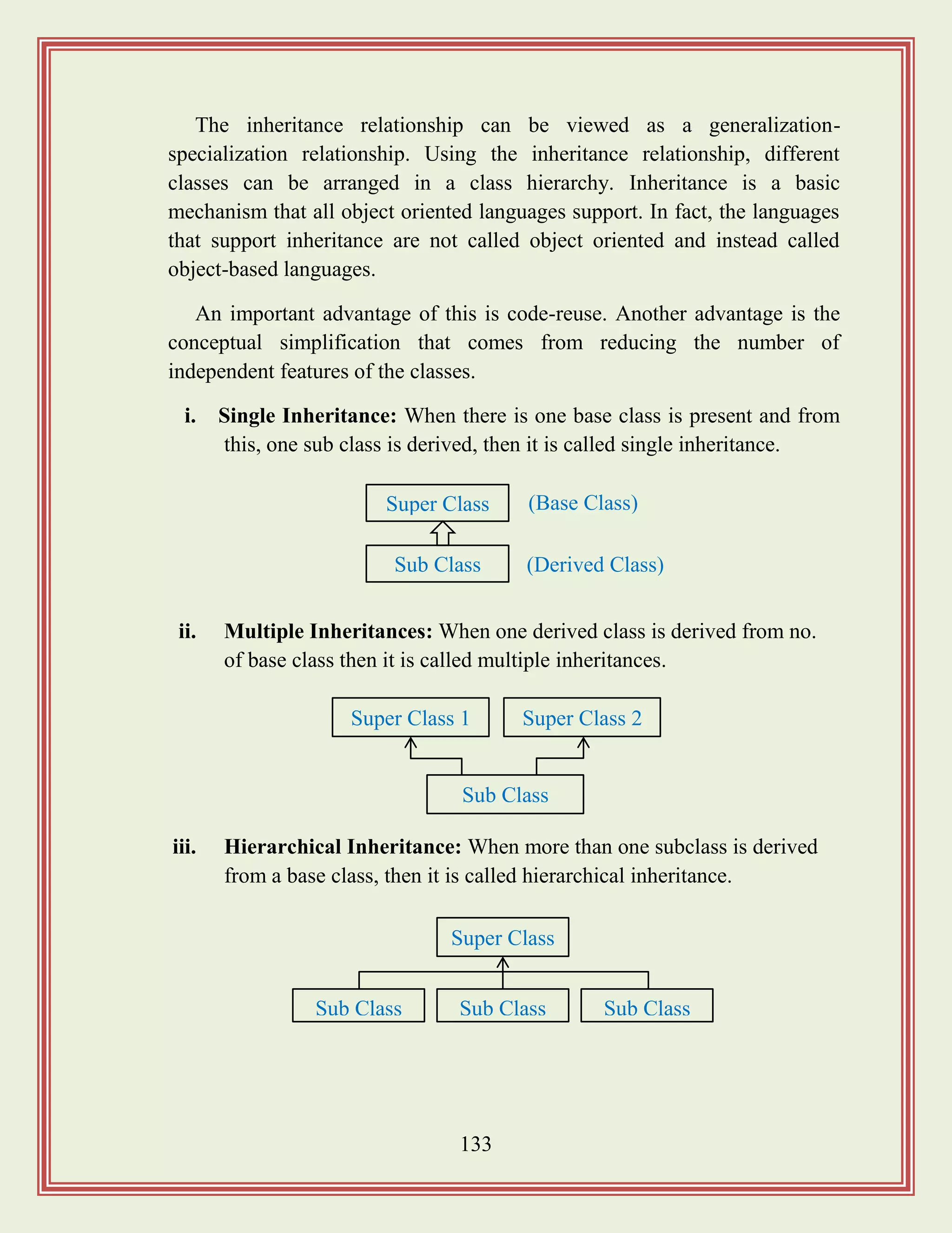
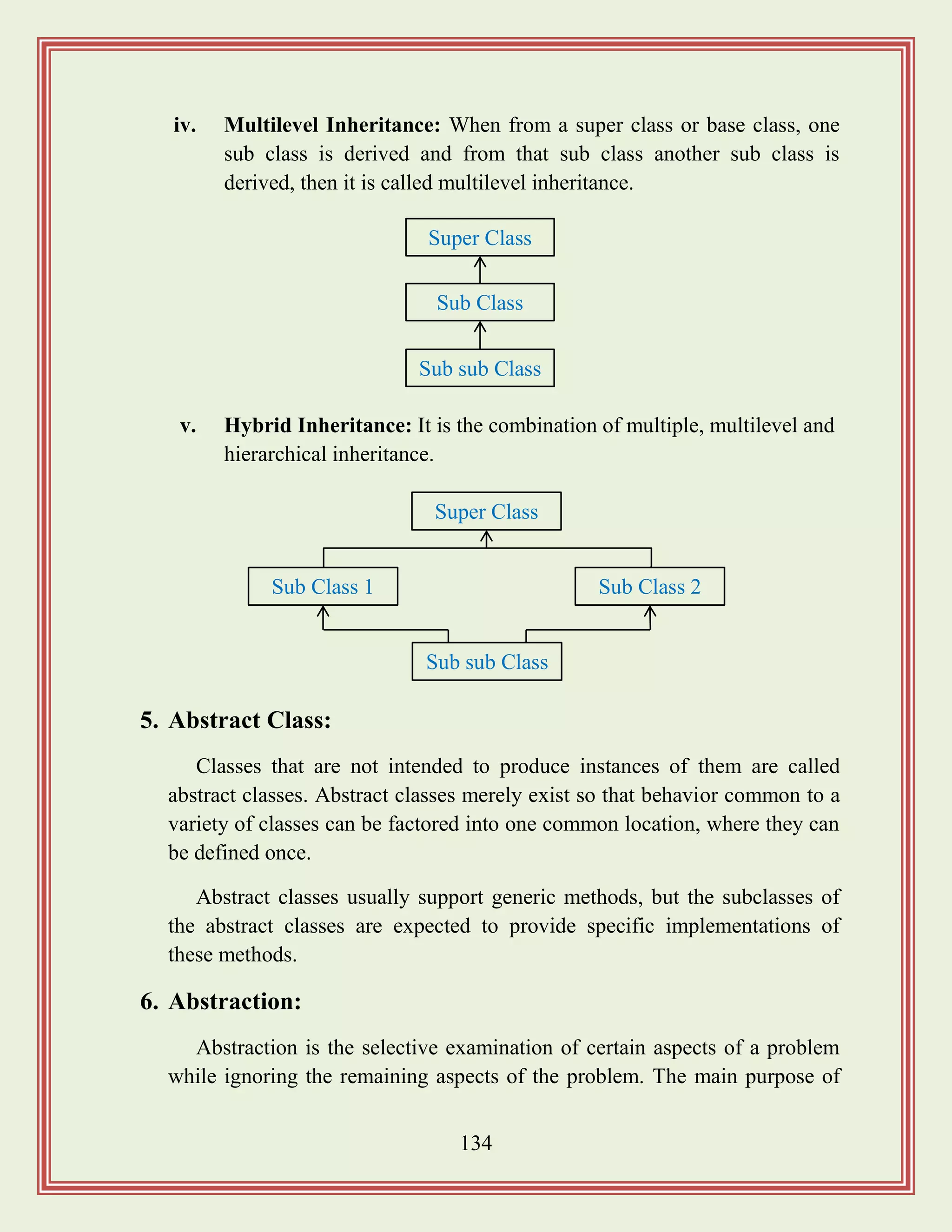
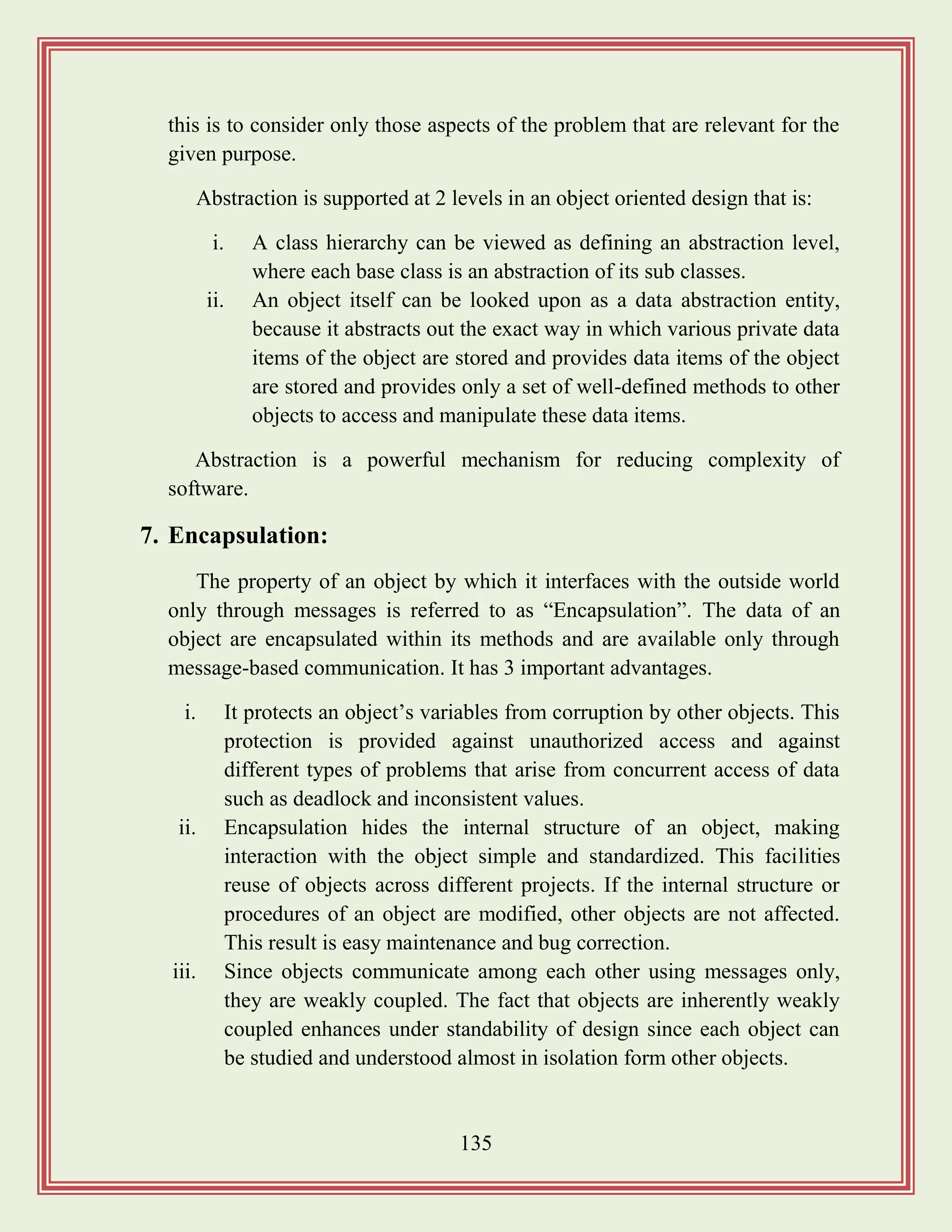
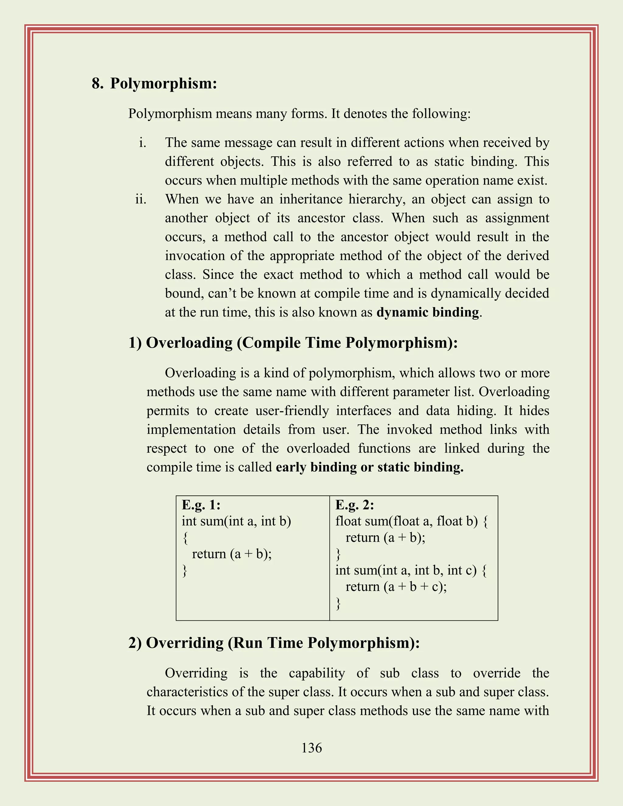
![137
identical signatures such that sub class hides the super class method. It
is called run time polymorphism.
In overriding, since the sub and super class objects have it
signature of a particular method, the type of actual object, which calls
the method, which is identified at run time. It is otherwise called as
dynamic binding.
Example:
class excel
{
void display title ()
{
system.out.println (“Microsoft excel”);
}
}
class workbook extends excel
{
void display title ()
{
super.displaytitle ();
system.out.println (“Book1”);
}
}
class AB
{
public static void main (string args [])
{
workbook book1 = new workbook ();
book1.display ()
}
}
9. Composite Objects:
Objects which contain other objects are called composite objects.
Containment may be achieved by including the pointer to one object as a](https://image.slidesharecdn.com/softwareengineeringstudymaterials-171005111336/75/Software-engineering-study-materials-138-2048.jpg)
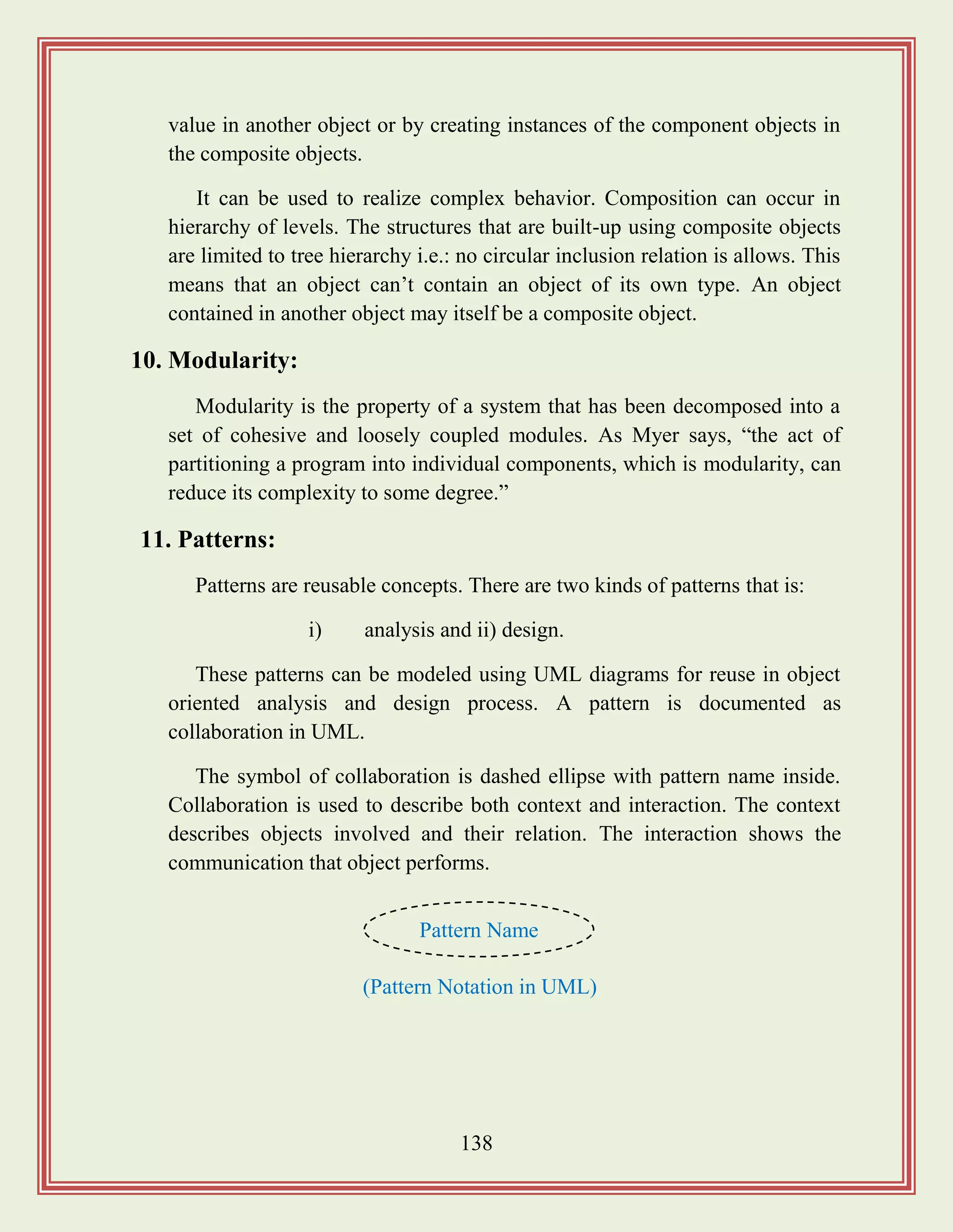
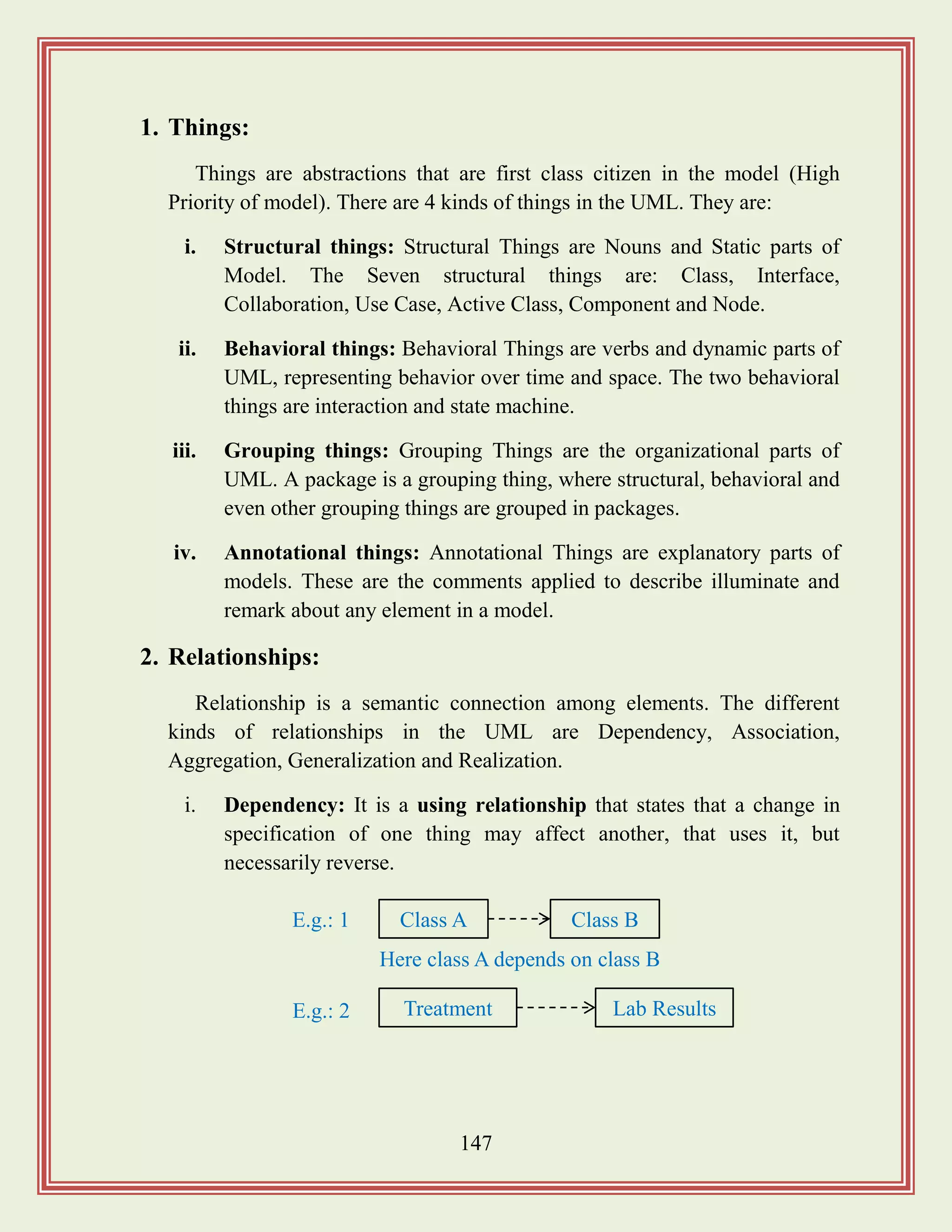
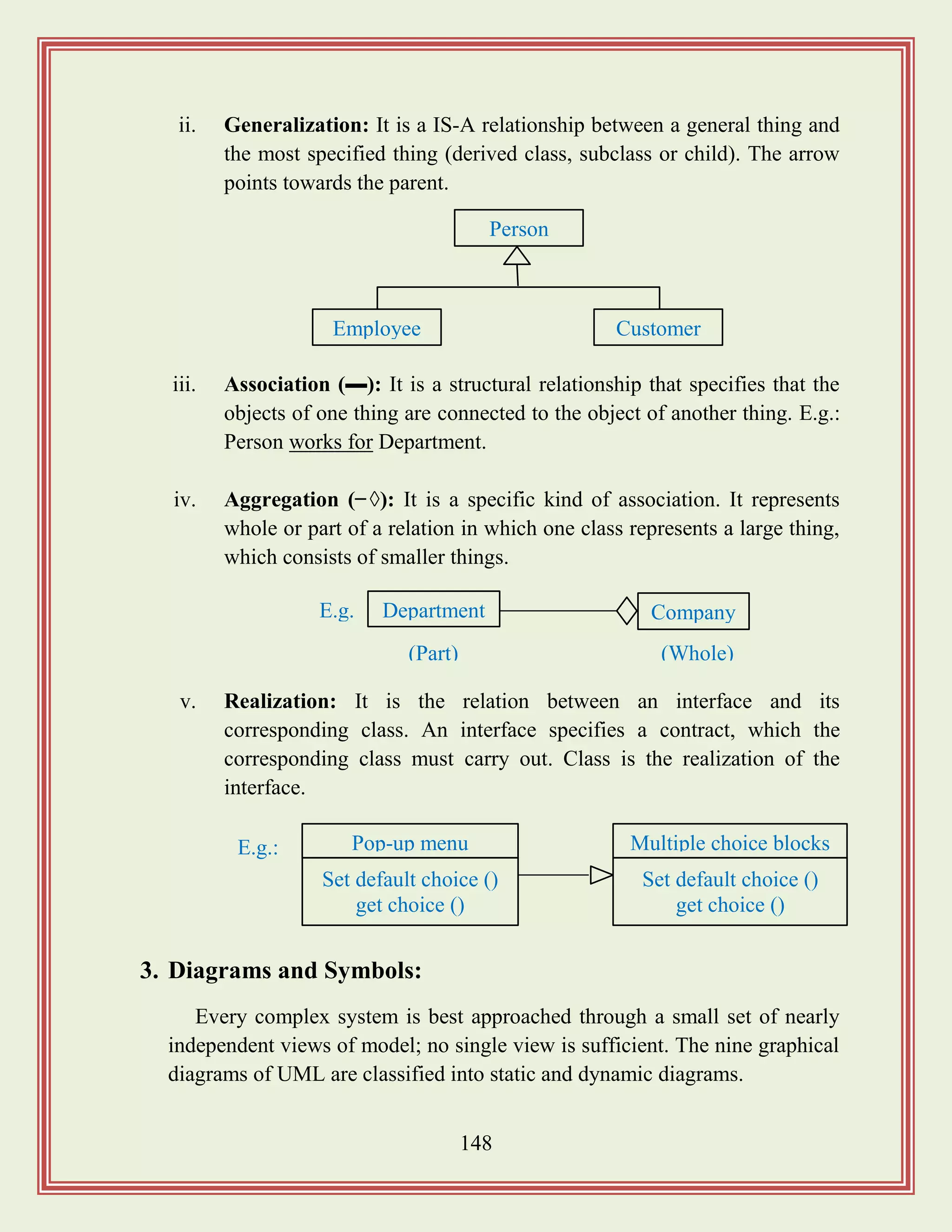
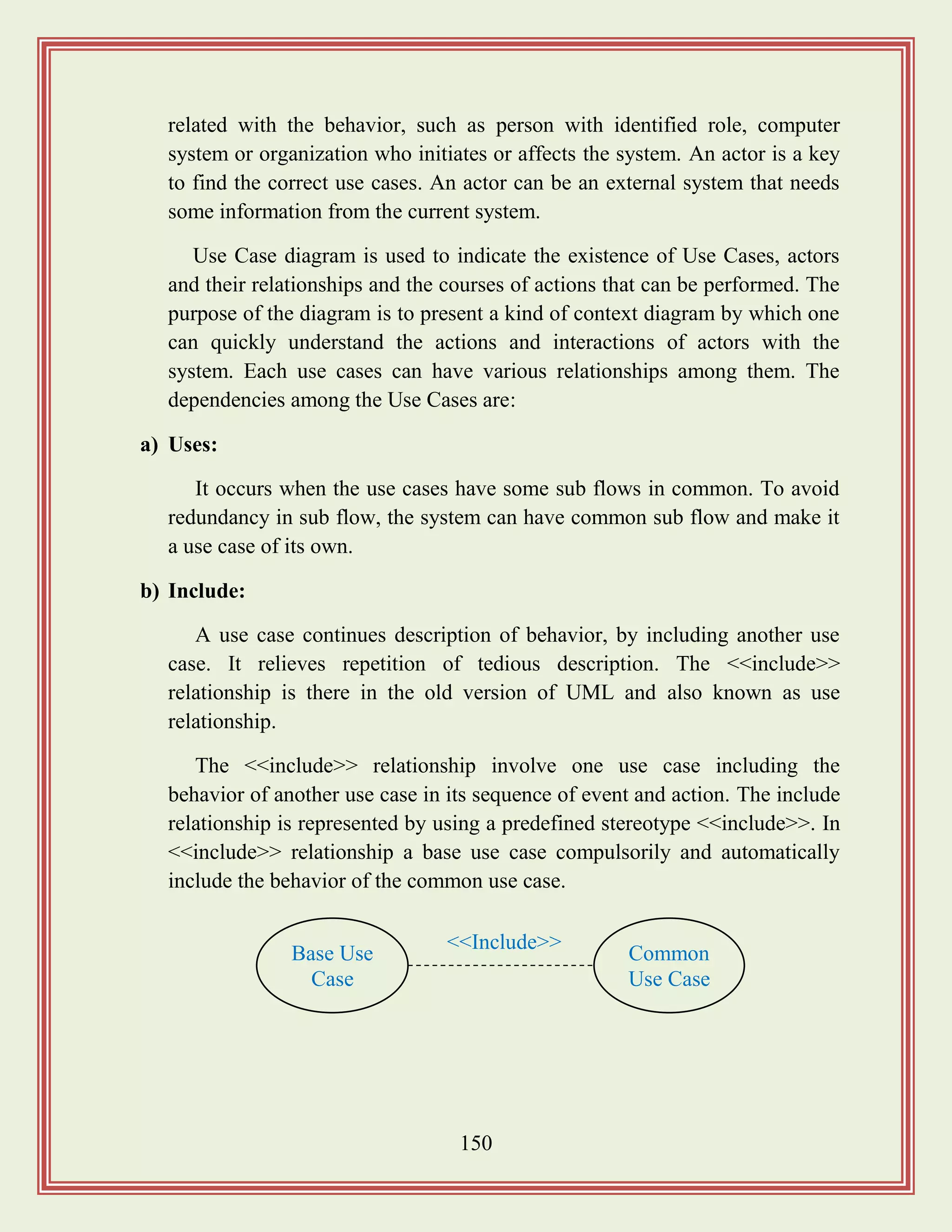
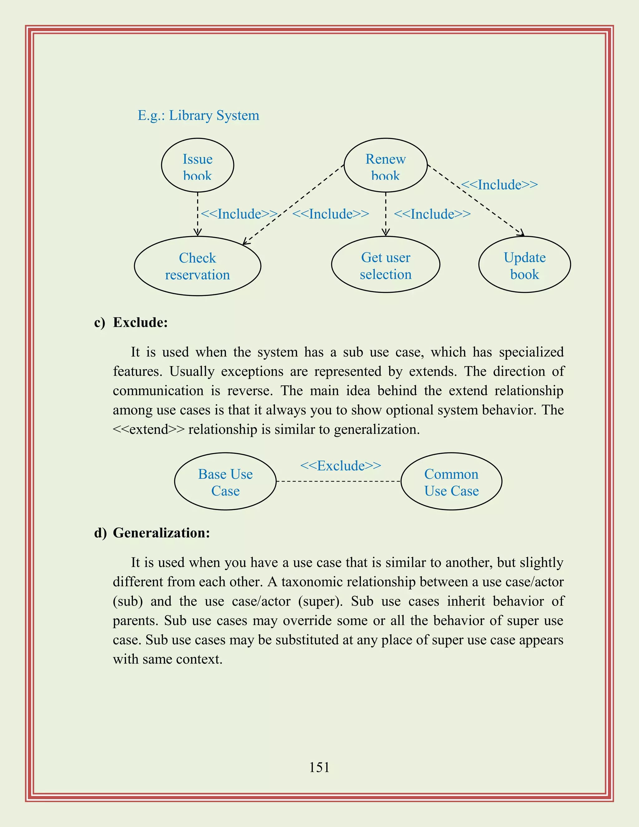
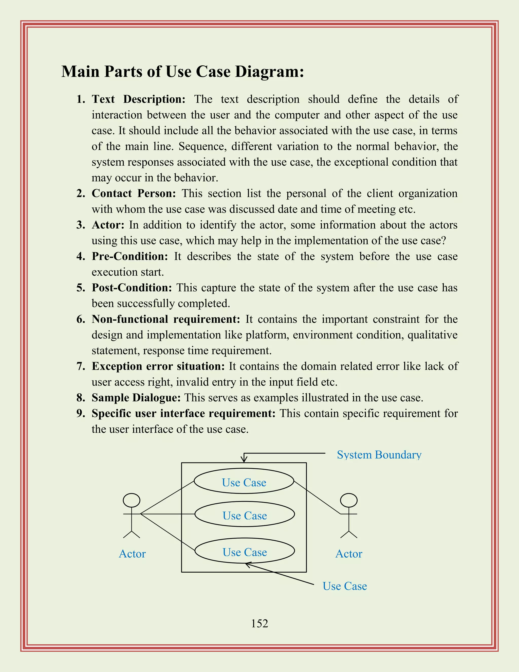
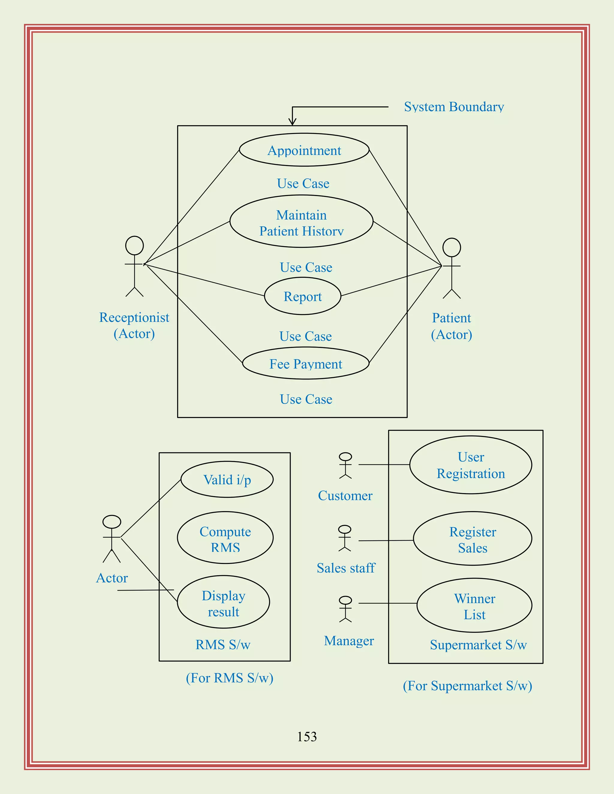
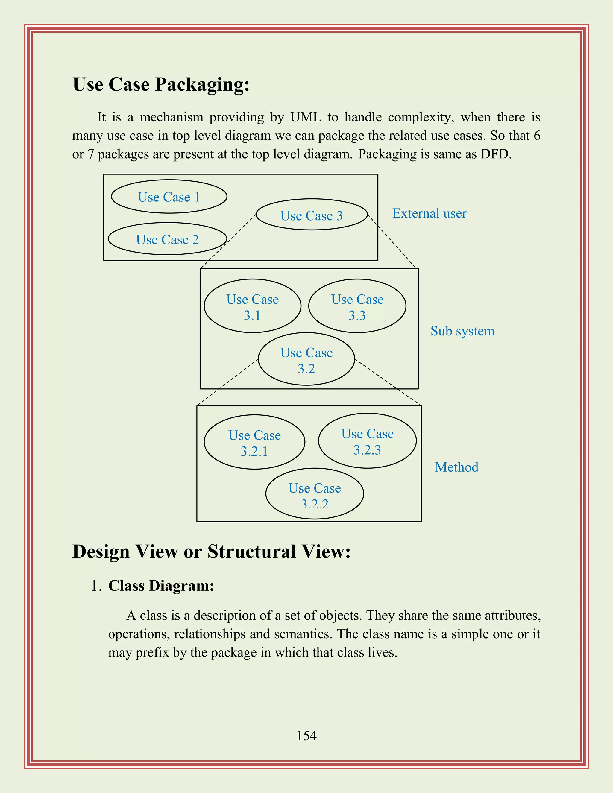
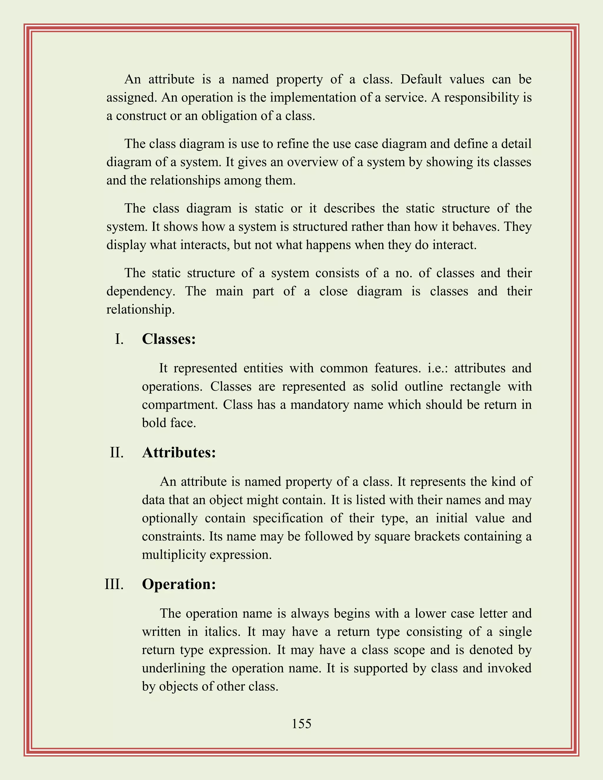
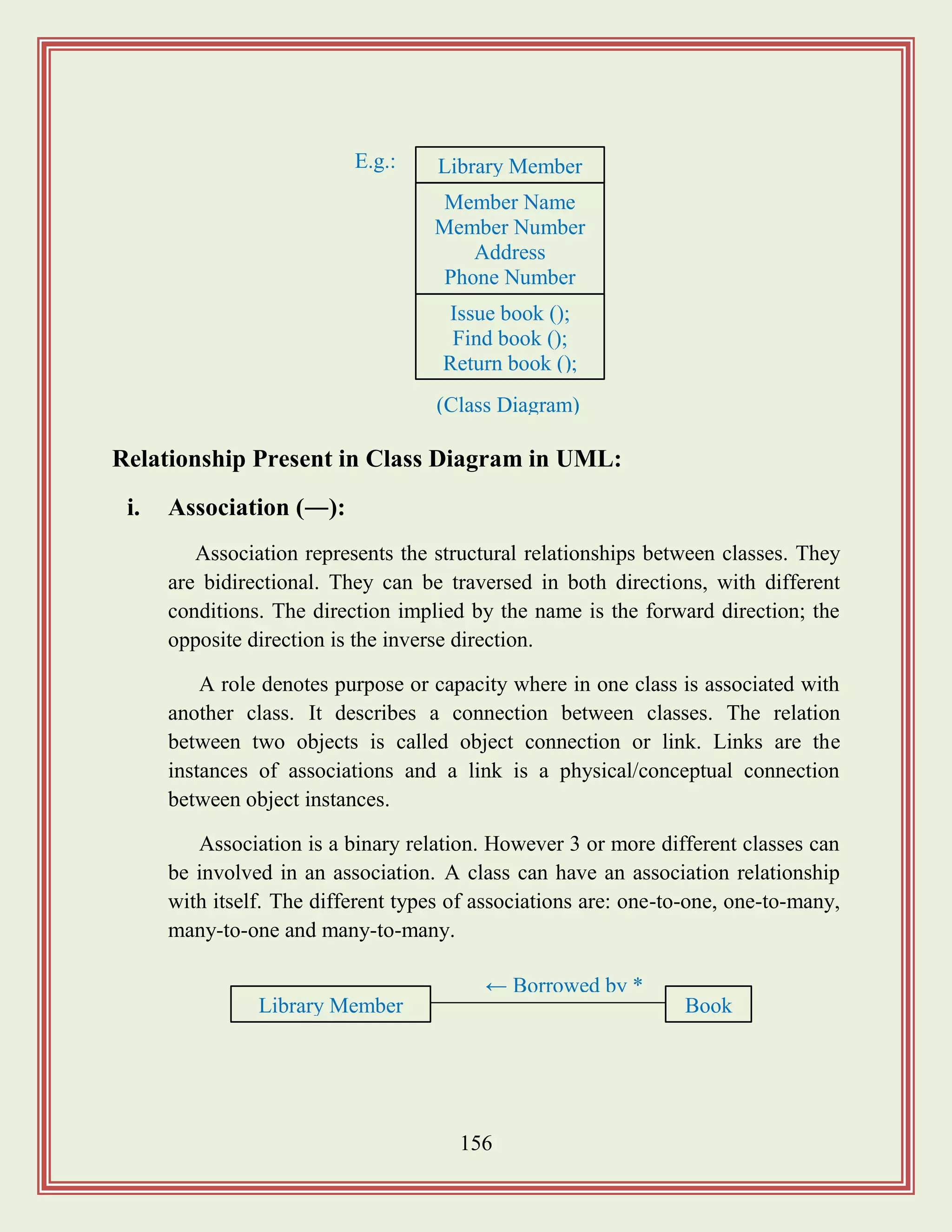
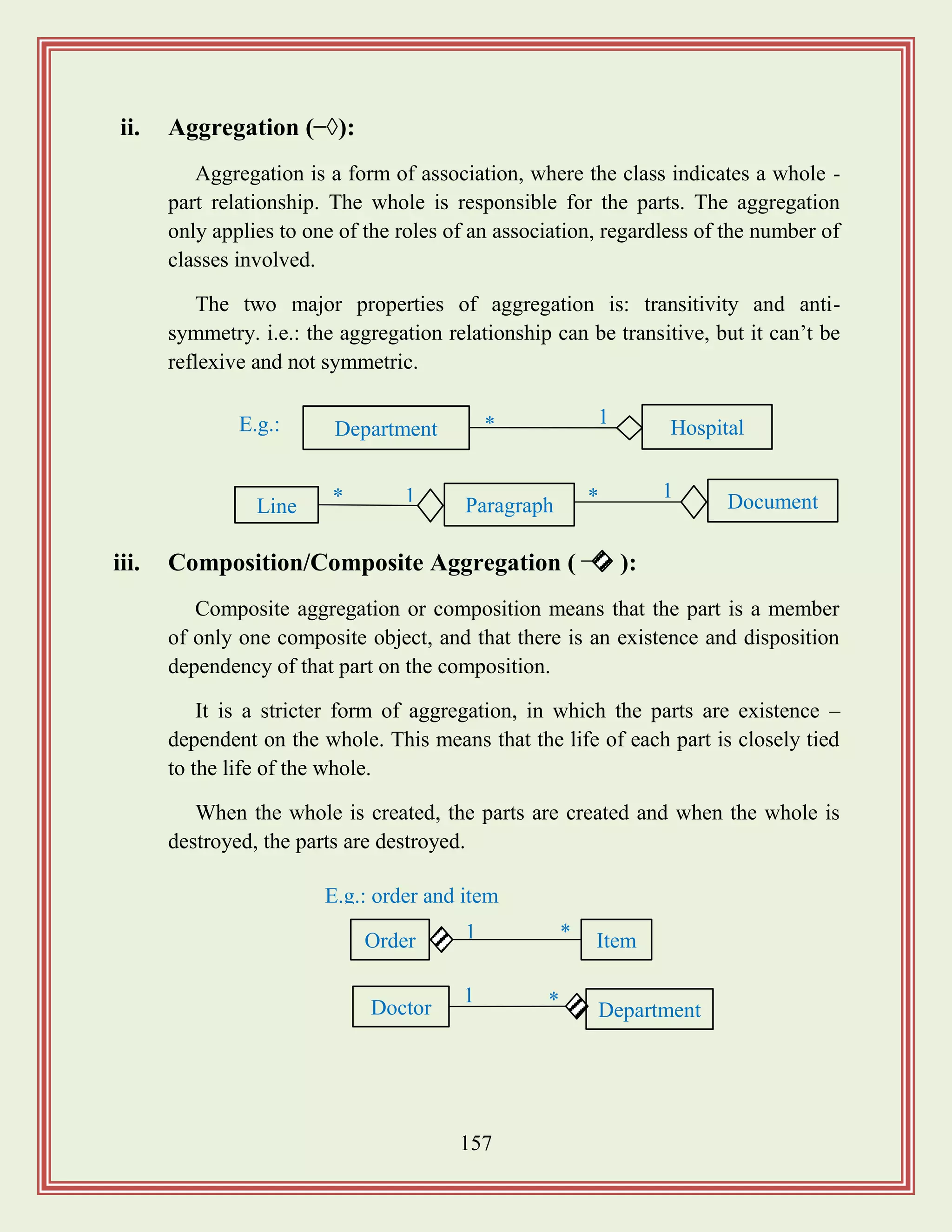
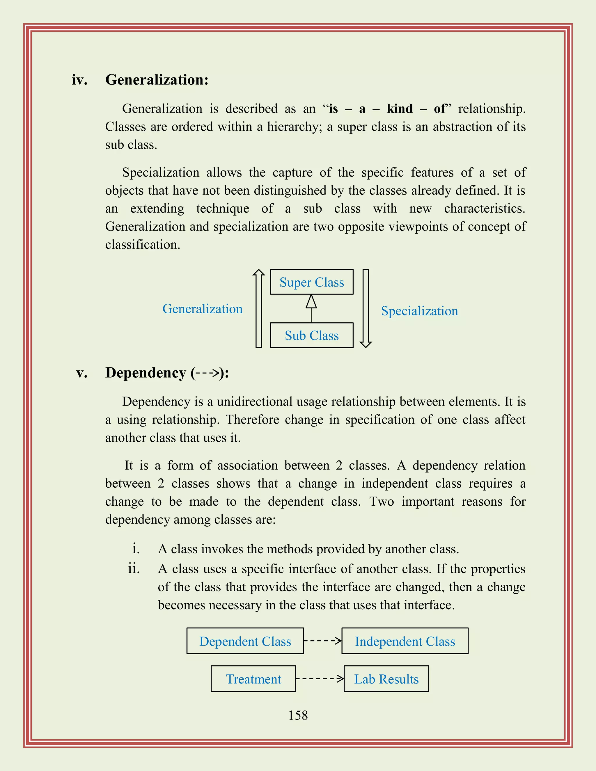
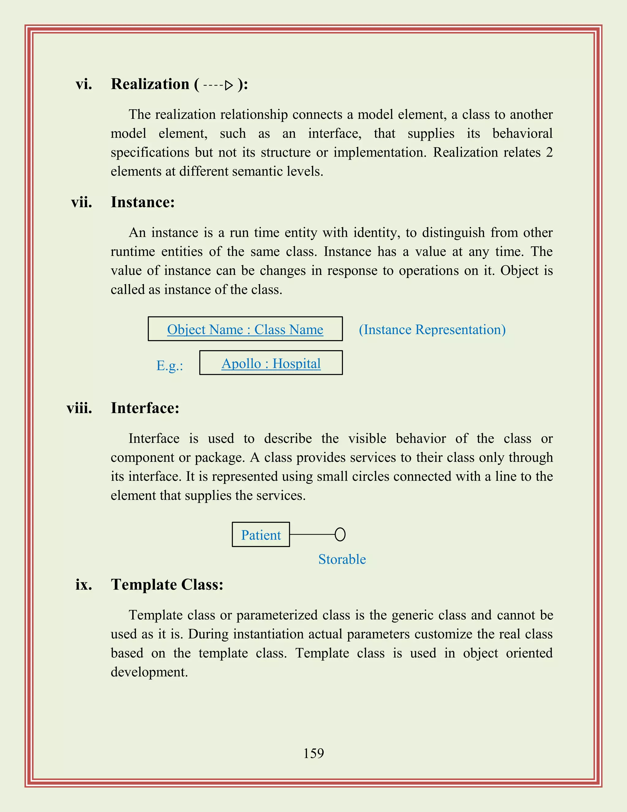
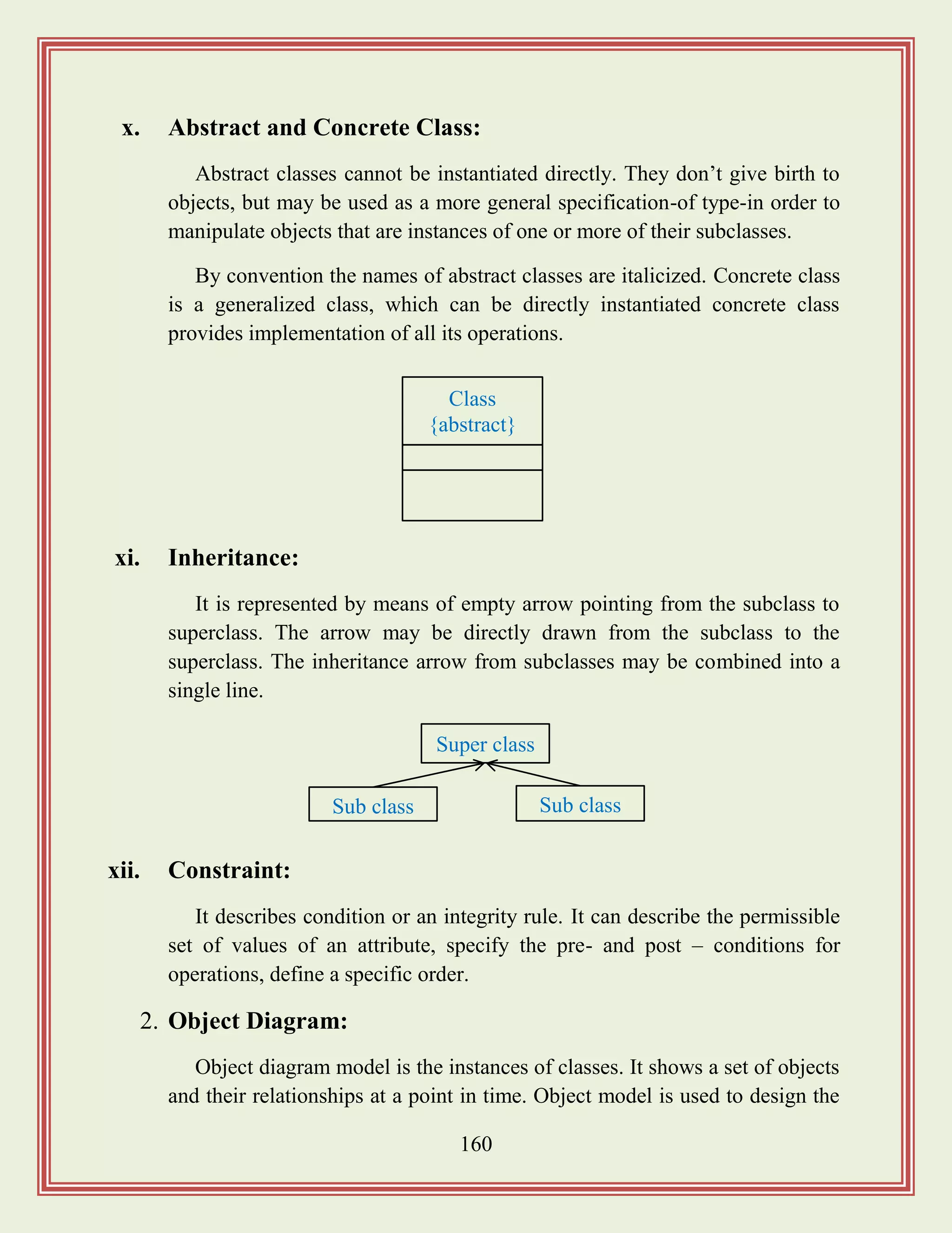
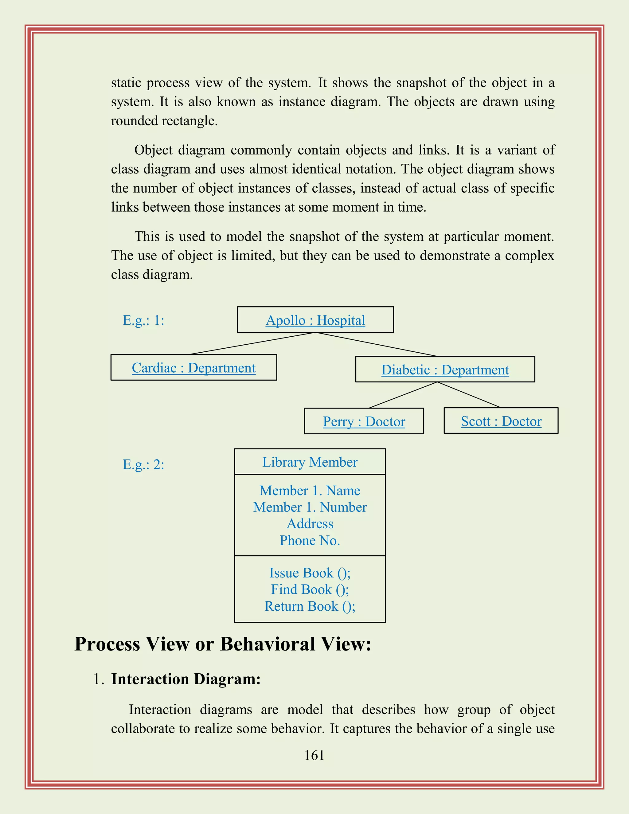
![163
a. Condition: that indicates that a message is send.
b. An interaction marker (*): show that the message is sent
many times to multiple receiver objects.
Patient Appointment Doctor Treatment
Confirms
Diagnosed
by
Gives
treatment
Feedback
Example:
: Library
Boundary
: Lib Book
Register
: Lib Book Renew
Controller
: Book
: Lib
Member
Renew book
Display
borrowing
Select
Book
Apology
Confirm
Find mem
Borrowing
Book
selected
Apology
Confirm
*find
Update
Updat
e
Member Borrowing
[Sequence Diagram of Database and the table of Library System]](https://image.slidesharecdn.com/softwareengineeringstudymaterials-171005111336/75/Software-engineering-study-materials-164-2048.jpg)
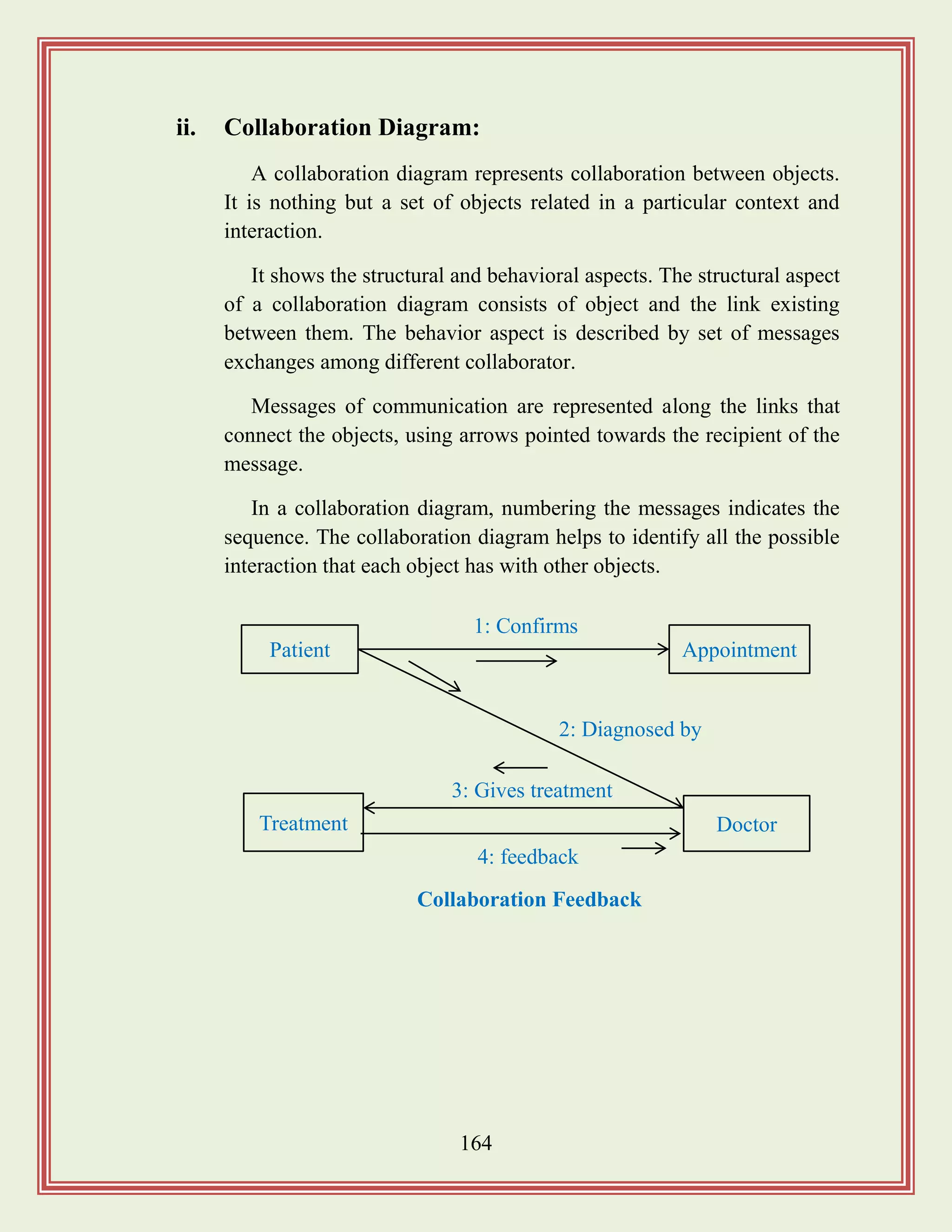
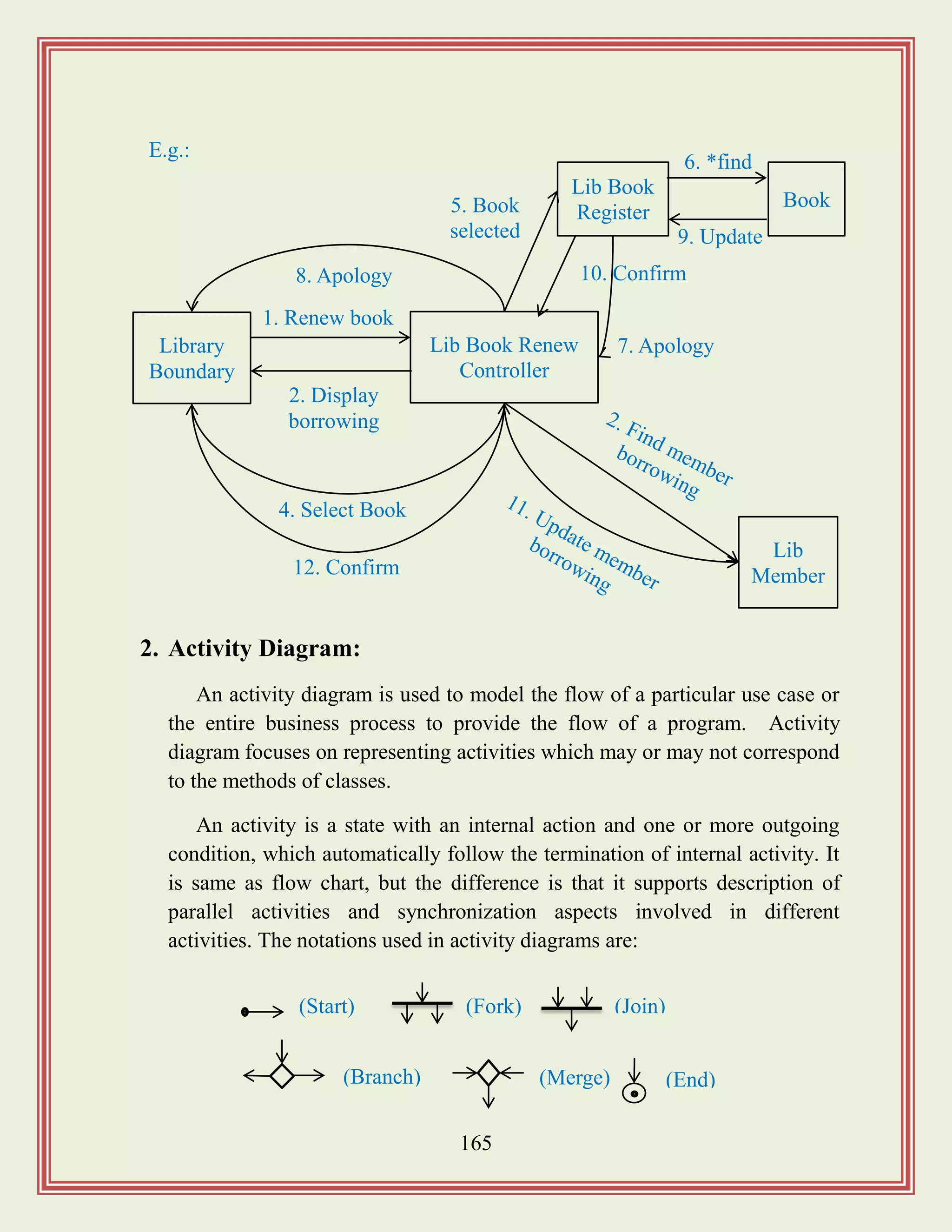
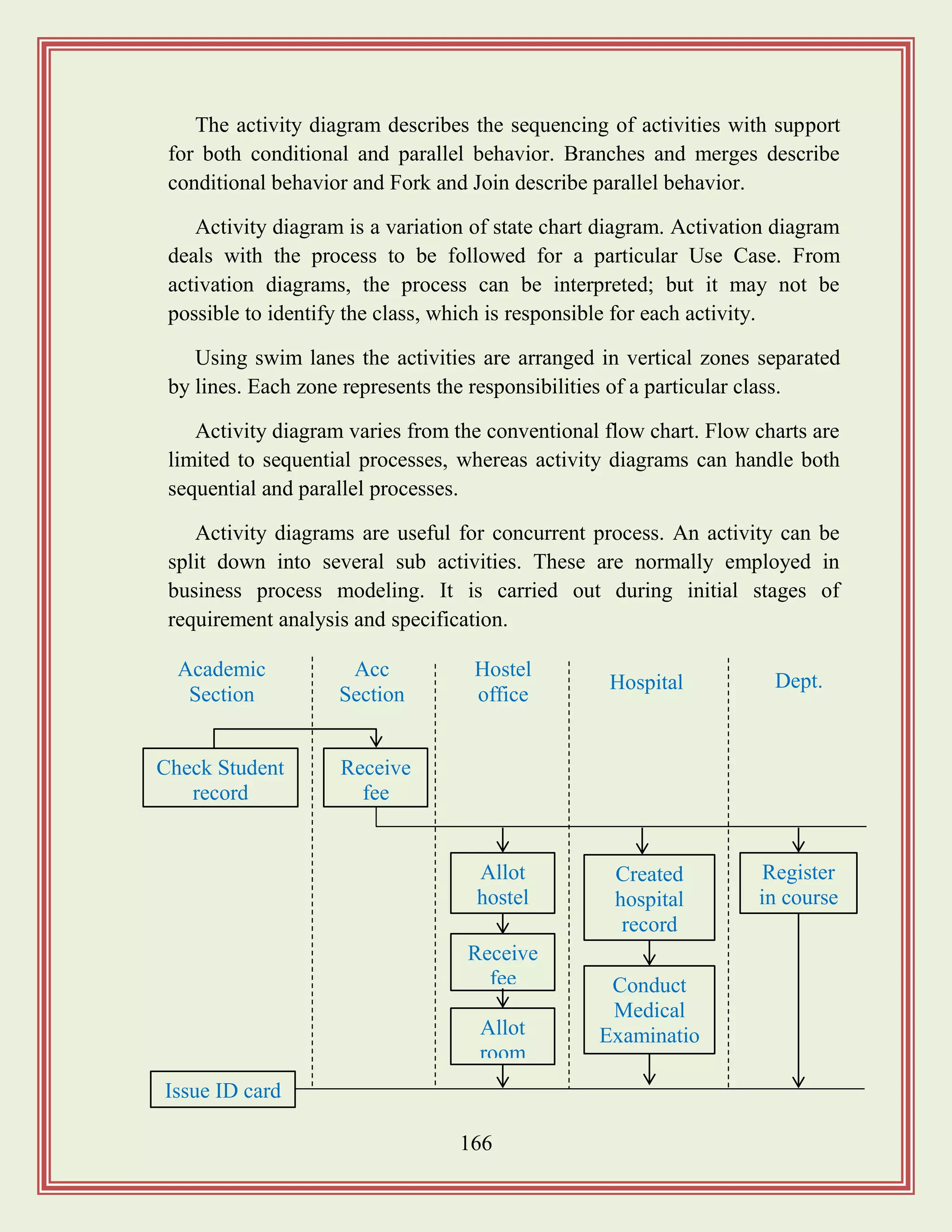
![167
3. State Chart Diagram:
Sometimes, it is desirable to model the behavior of a single object class,
especially if the class illustrates significant dynamic behavior. State
chart/State Transition diagram may be created for these types of classes.
It shows a life history of a given class, the events that causes a transition
from one state to another, and the action that results from a state change. So
the state chart diagrams are useful to model the reactive systems.
It is used to model how the state of an object changes in its life time.
These are good at describing how the behavior of an object changes across
several use case execution. Reactive systems can be defined as a system that
corresponds to external or internal events.
Classify
diabetic type
Study the
patient History
Prescribe
for lab test
Treatment
for diabetic
Classify the
patient work type
Check height
and weight
No treatment Next
Person in the queue
Branch
No symbols
State
(End)
[Activity Diagram of Diagnosis of Diabetic Patient]](https://image.slidesharecdn.com/softwareengineeringstudymaterials-171005111336/75/Software-engineering-study-materials-168-2048.jpg)
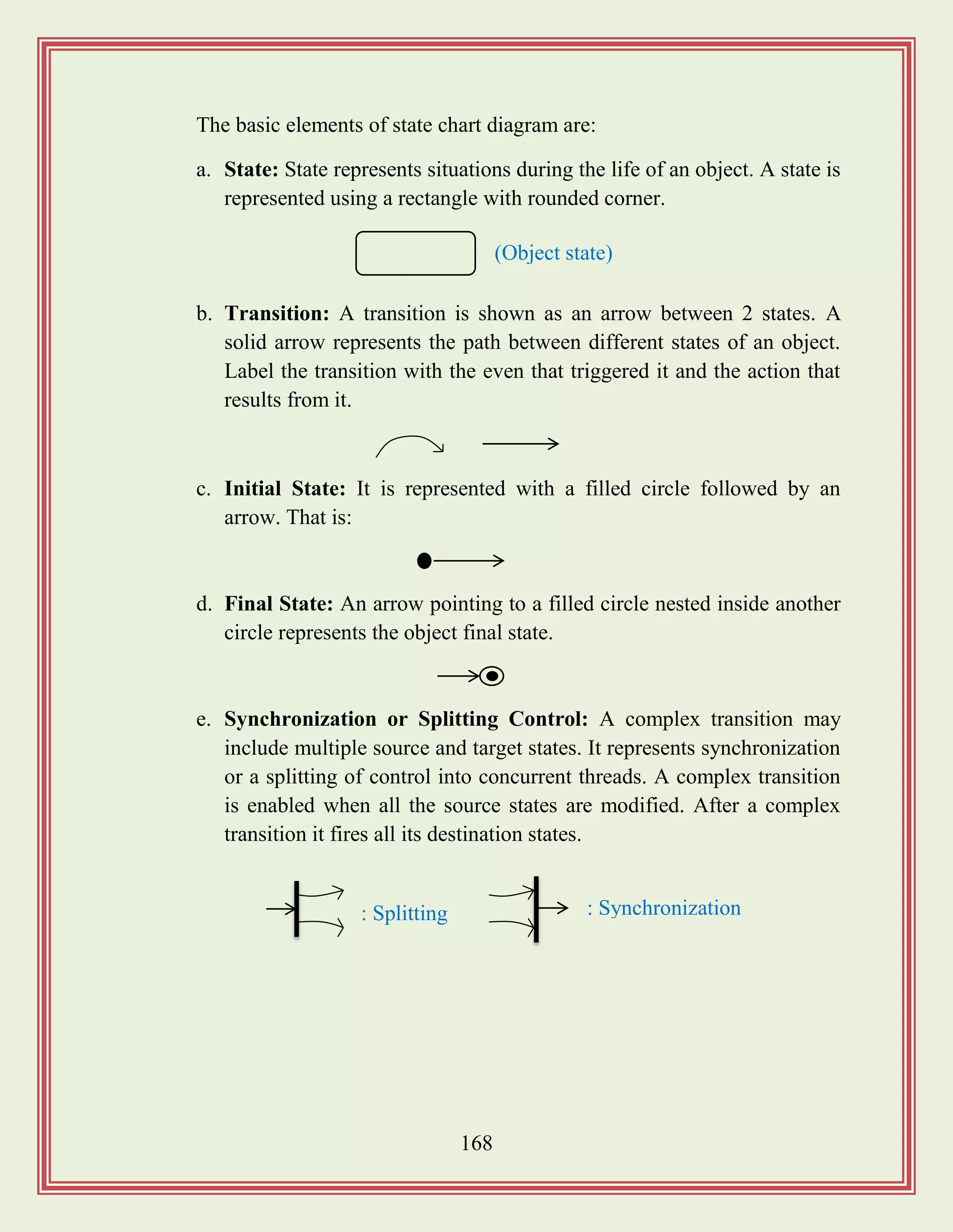
![169
Implementation View and Deployment View:
1. Implementation Diagrams:
Implementation diagrams show the implementation phase of system
development and its architecture. Implementation is described by physical
and logical structure.
Unprocessed
order
Rejected
order
Accepted
order
[Reject]
checked
[Accept]
checked
Accepted
order
Accepted
order
[All time available]
new supply
[Sometimes
not available]
Processed
[All items available]
Processed or deliver
Order received
Idle
Send order
request
Selected special or
normal order
Order confirmation
Dispatch order
Confirm order
Transitio
n
Transaction CompleteFinal state
Initial state
Initial state of
the object](https://image.slidesharecdn.com/softwareengineeringstudymaterials-171005111336/75/Software-engineering-study-materials-170-2048.jpg)
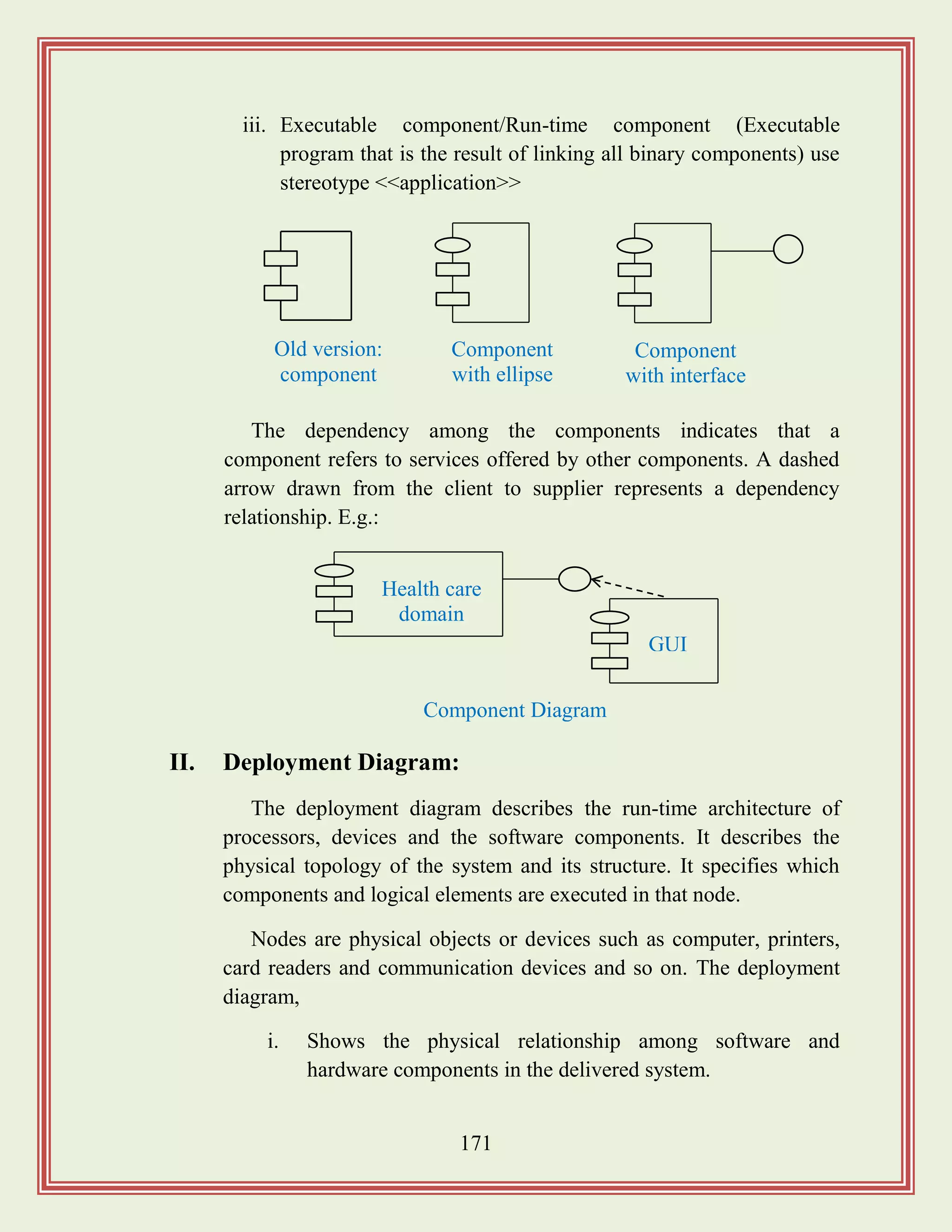
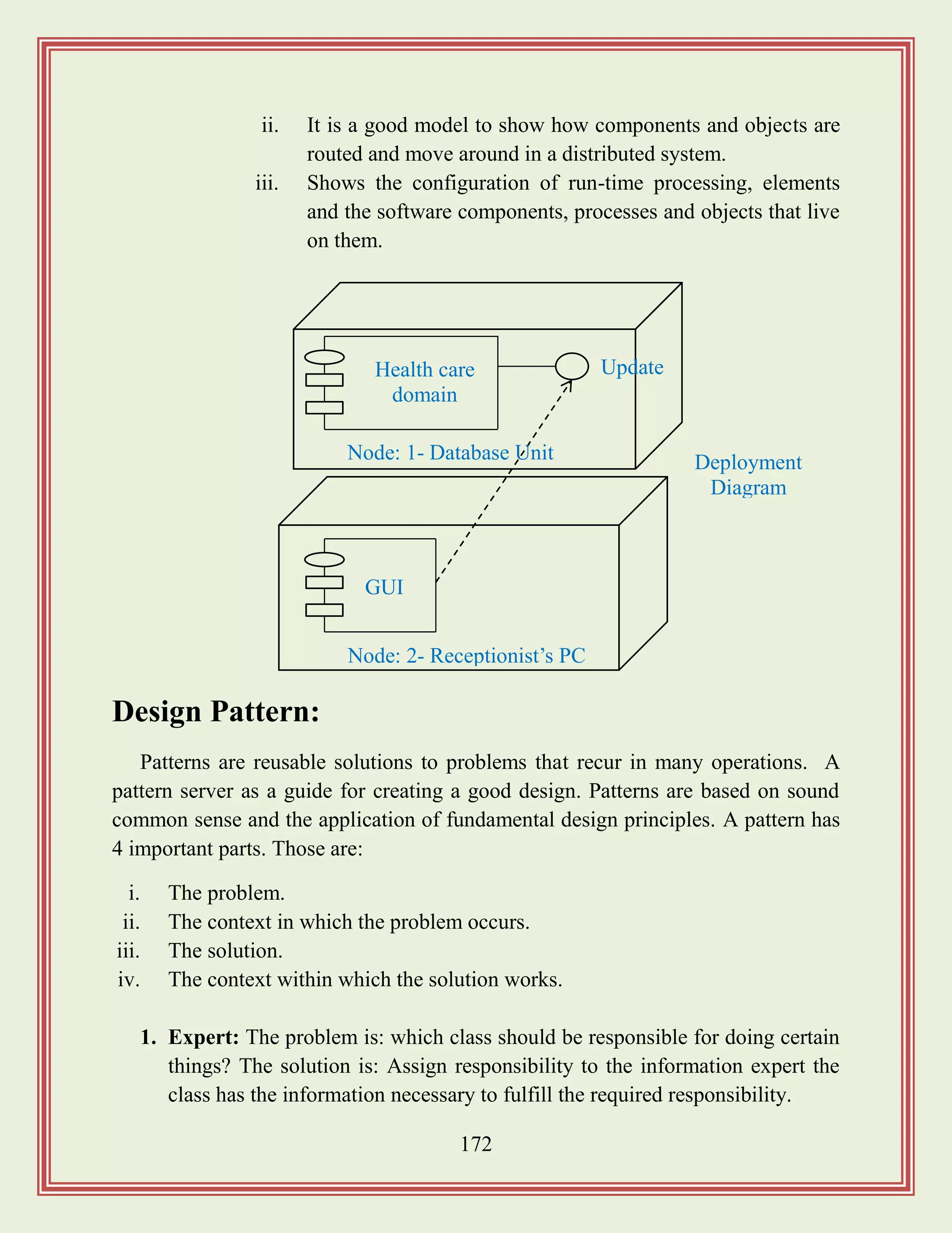
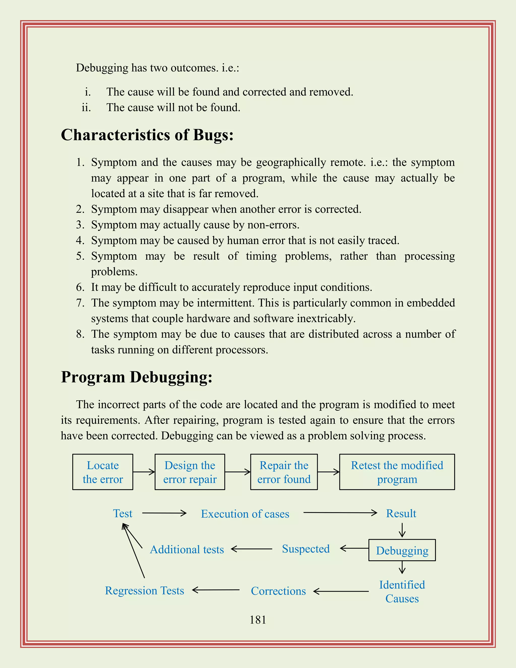
![183
b) Dynamic Analysis Tool:
This technique requires the program to be executed and its actual
behavior recorded. A dynamic analyzer usually instruments the code of the
software to be tested in order to record the behavior of the software for
different test cases.
After the software is tested and behavior is recorded, dynamic analysis
tool carried out a post execution analysis and produces reports which
describe the structured coverage that has been achieved by the complete test
suite for the program.
Testing:
It is a program, consists of providing the program with a set of test inputs and
observing if the program behaves as expected some commonly used terms
associated with testing.
The aim of the testing process is to identify all defects existing in a software
product. Some commonly used testing associated with testing are:
a. Failure: It is a manifestation of an error. It is the ability of the software to
perform a required function to its specification.
b. Fault: It is an incorrect intermediate state that may have been entered during
program execution. E.g.: a variable value is different from what it should be.
c. Test Cases: It is the triplet [1, S, 0] where „1‟ is the data input to the system
„S‟ is the state of the system at which the data is input and „0‟ is the expected
output of the system.
d. Test Suite: It is the set of all test cases with which as given software product
is to be tested.
Characteristics of Testing:
1. To perform effective testing, a software team should conduct effective
formal technical review.](https://image.slidesharecdn.com/softwareengineeringstudymaterials-171005111336/75/Software-engineering-study-materials-184-2048.jpg)
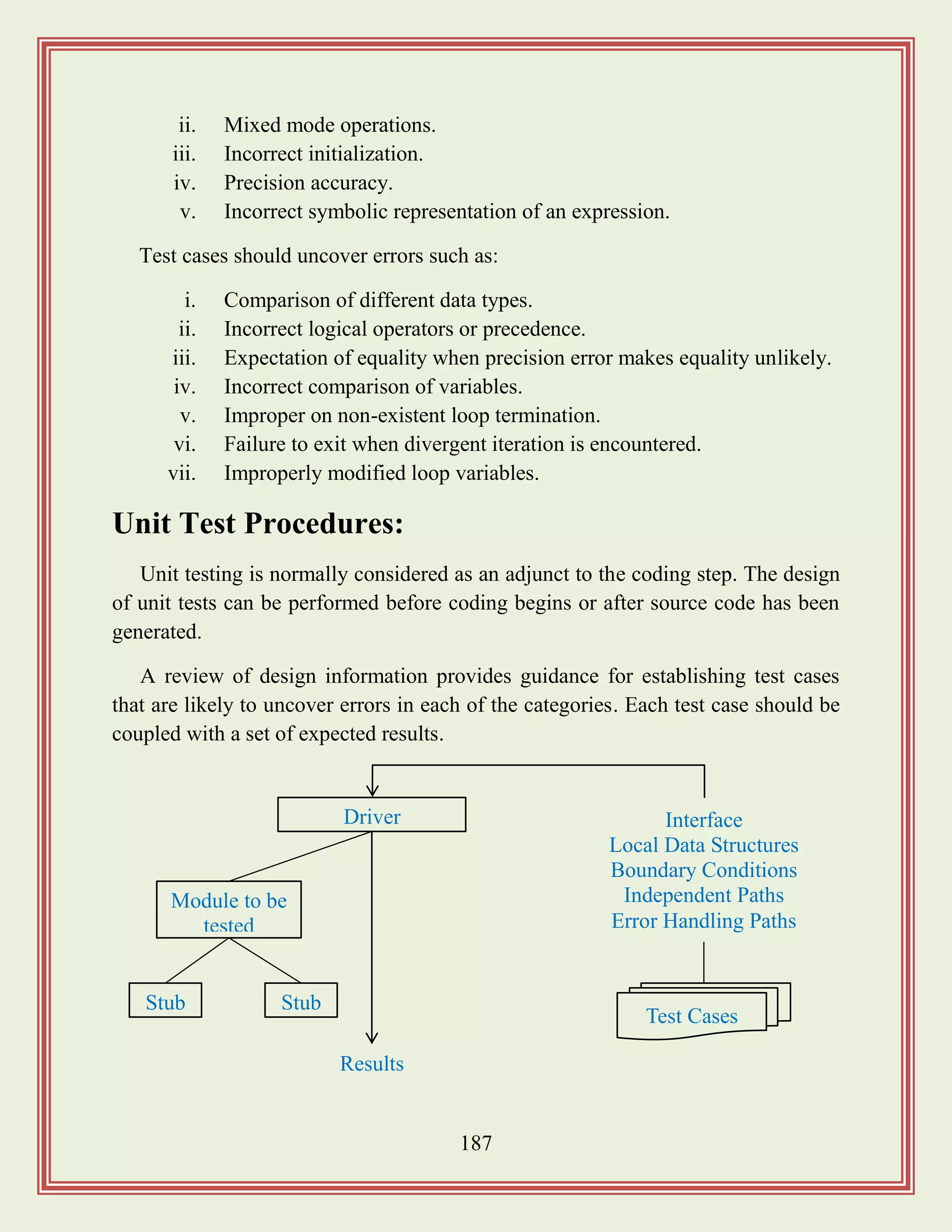
![188
Driver and Stub Modules:
In order to test a single module, we need a complete environment to provide.
i.e.: necessary for executing a module. That is besides the module under test itself;
we need the following in order to be able to test the module.
i. The procedure belonging to other modules that the module under test calls.
ii. Nonlocal data structures that the module accesses.
iii. A procedure to call the functions of the module under test with appropriate
parameters.
Modules required to provide the necessary environment are usually not
available until they have been unit tested; so stub and driver are designed to
provide complete environment for a module.
A stub procedure is dummy procedure that has the same I/O parameters as the
given procedure but has a highly simplified behavior. A driver module would
contain the nonlocal data structures accessed by the module under test and would
also have the code to call the different functions of the module with appropriate
parameter values.
Drivers and stubs represent overhead. That is both are software that must be
written but that is not delivered with the final software product. If drivers and stubs
are kept simple, actual overhead is relatively low.
Unit testing is simplified when a component with high cohesion is designed.
When only one function is addressed by a component, the number of test cases is
reduced and errors can be more easily predicted and uncovered.
Driver
Module under test
Stub Module
Global data
[Unit testing with the help of driver and stub module]](https://image.slidesharecdn.com/softwareengineeringstudymaterials-171005111336/75/Software-engineering-study-materials-189-2048.jpg)
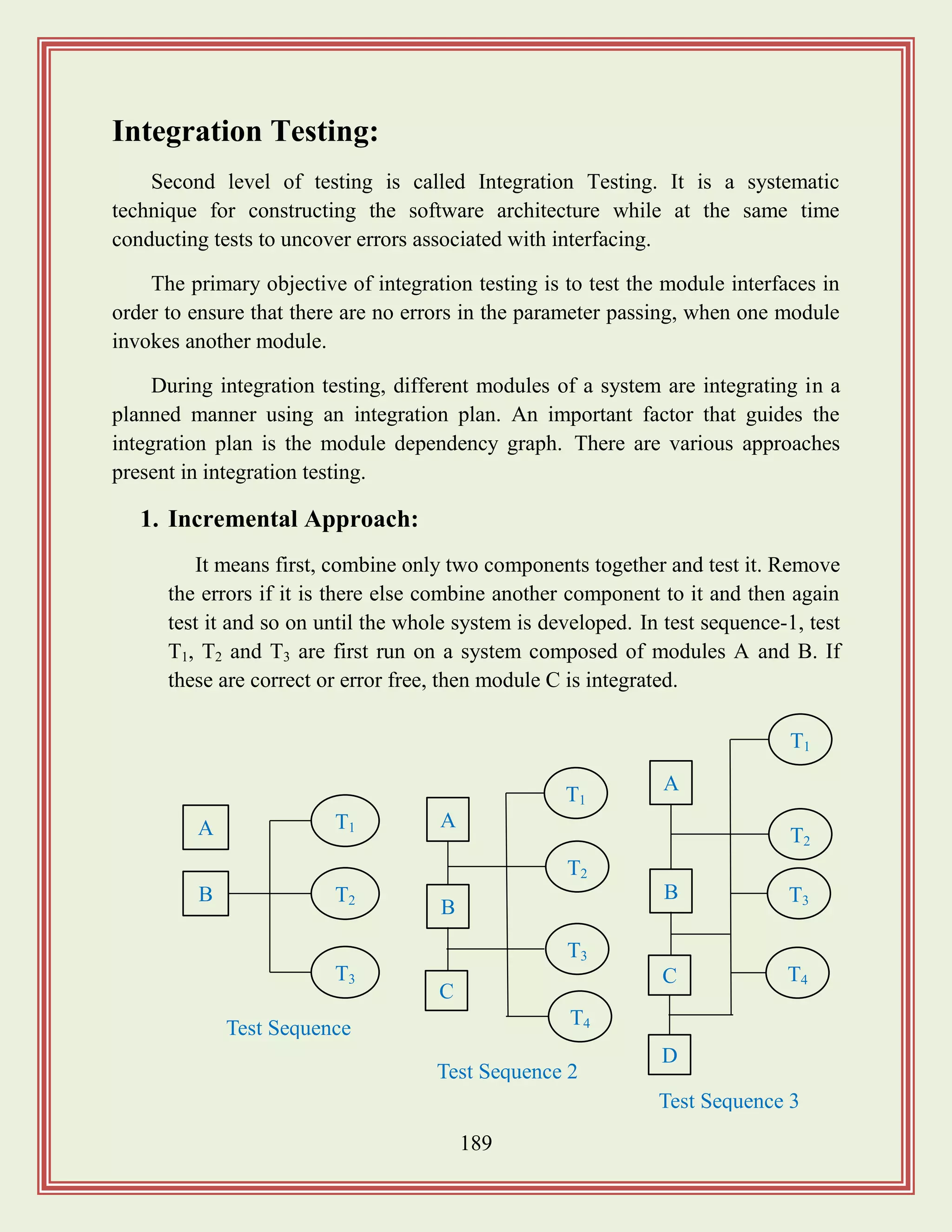
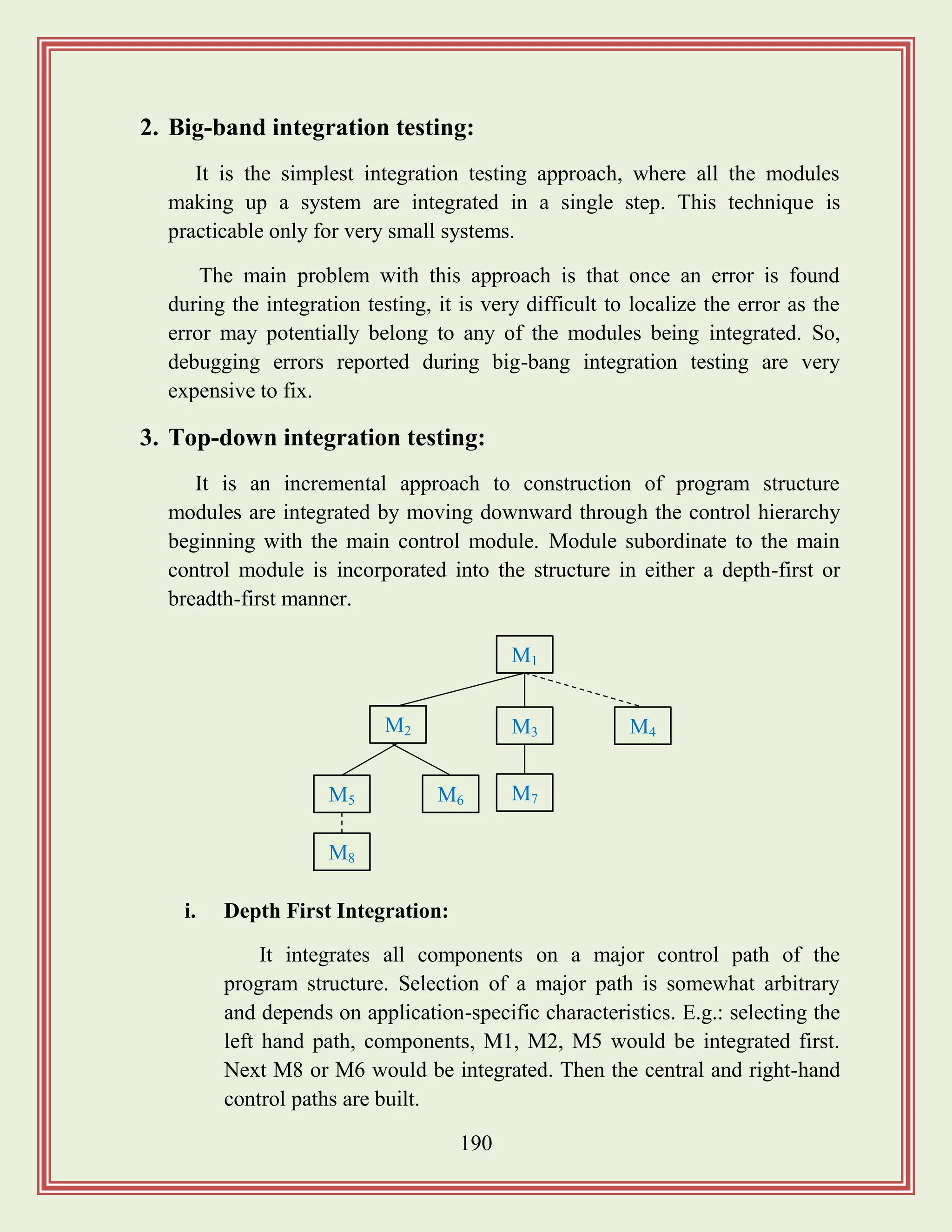
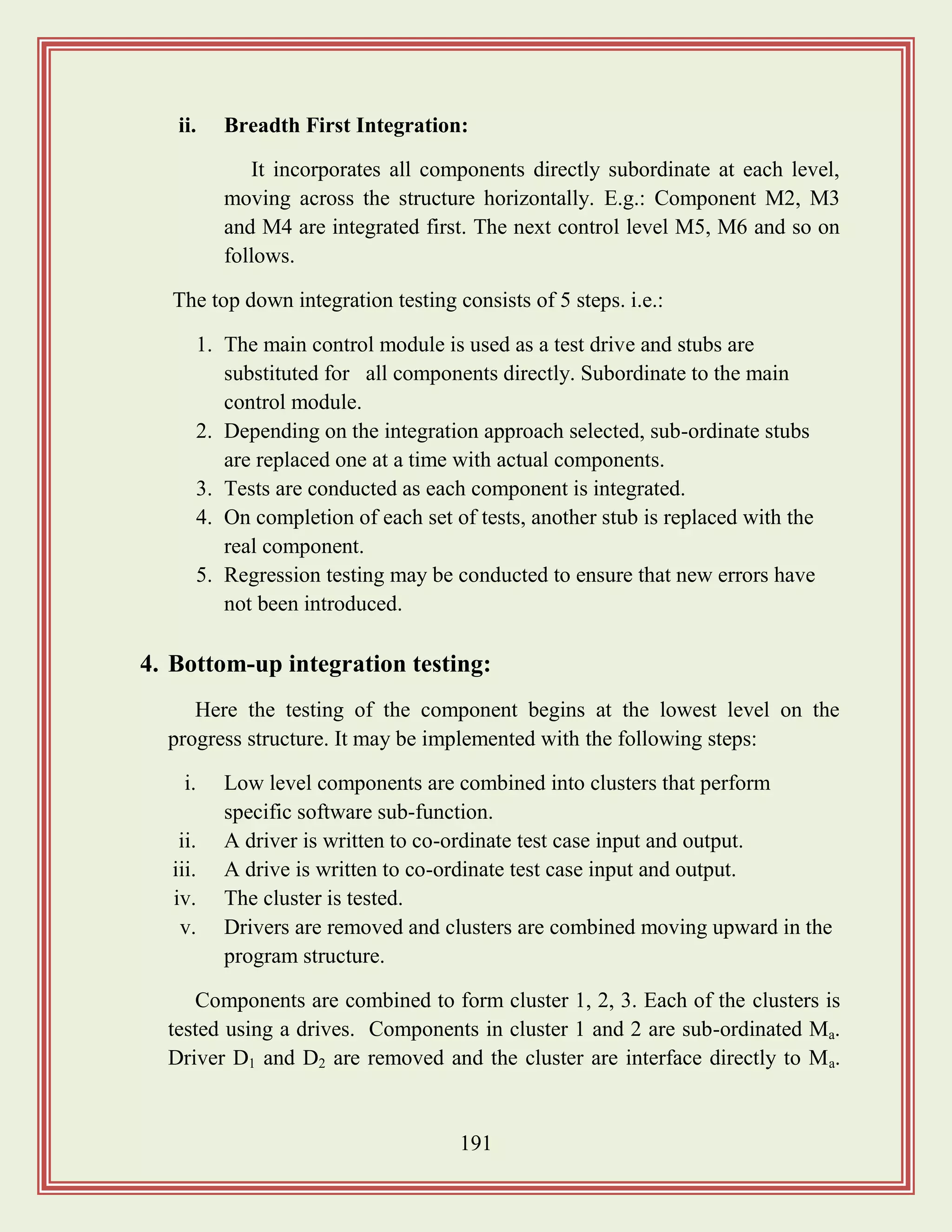
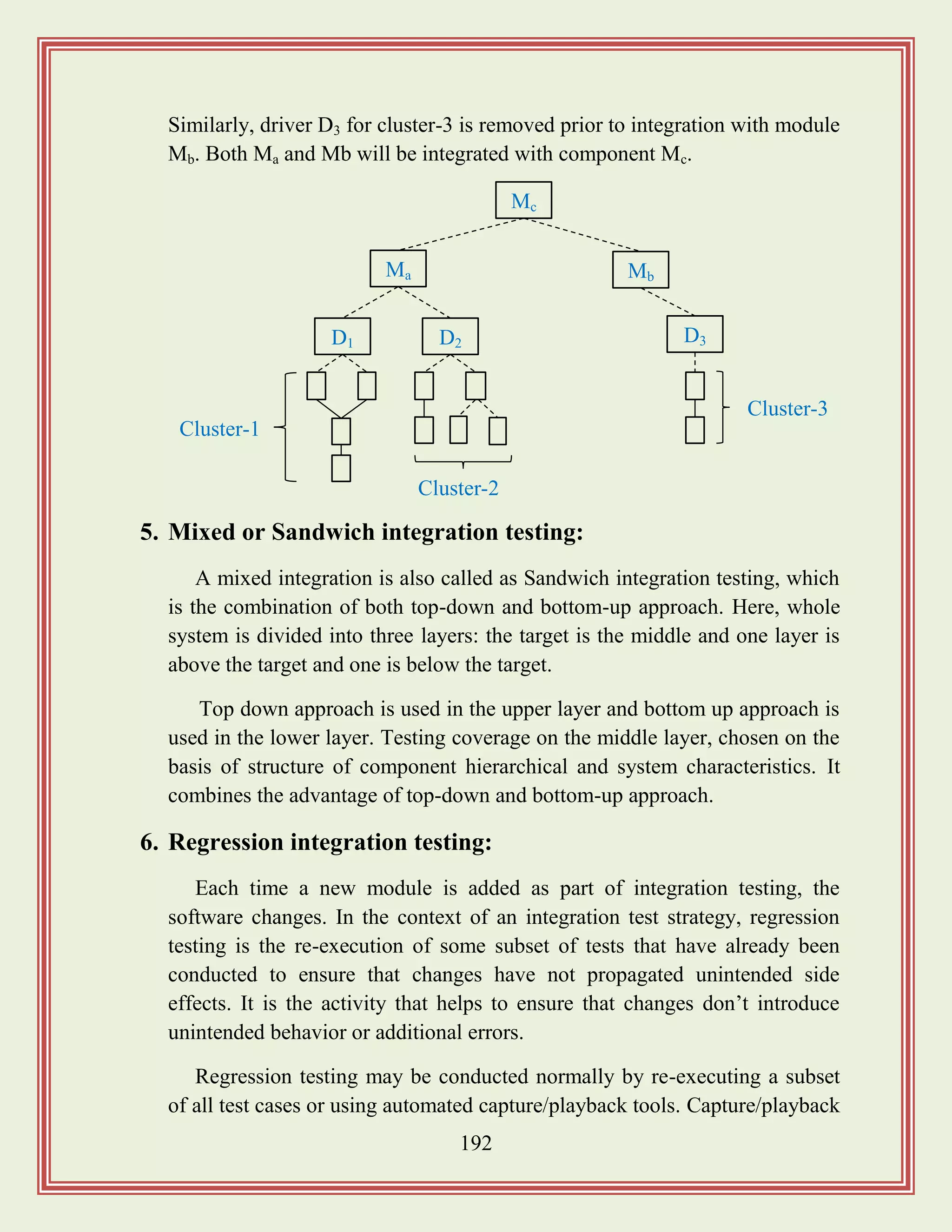
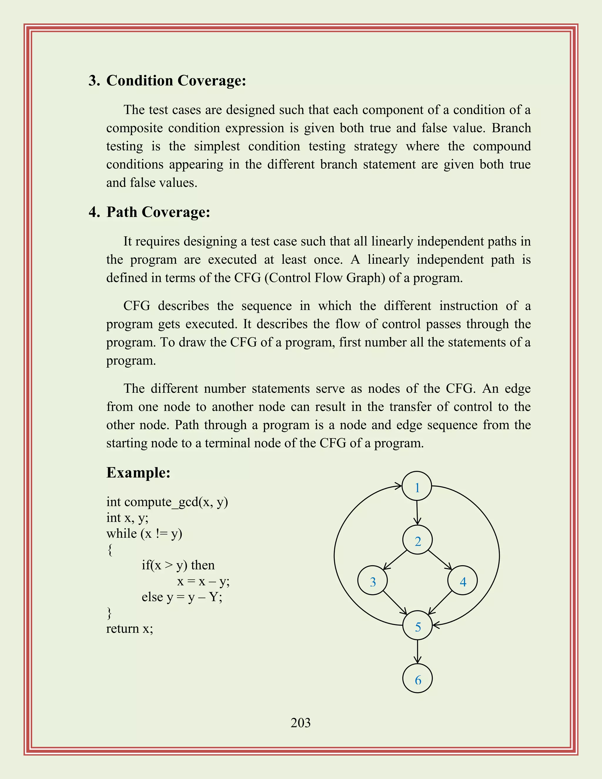
![205
1. Condition testing:
Condition testing is a test design method that exercises the logical
conditions contained in a program module. A simple condition is a Boolean
variable or a relational expression, possibly preceded with one NOT(¬)
operator.
A relational expression takes form: E1<relational-operator>E2, where E1
and E2 are arithmetic expressions and <relational-operator> is one of the
following: <, ≤ , =, ≠, >, ≥. A compound condition is composed of two or
more simple conditions, Boolean operators and parenthesis.
2. Data Flow Testing:
The dataflow testing method selects test paths of a program according to
the locations of definitions and uses of variables in the program.
To illustrate the dataflow testing approach, assume that each statement in
a program is assigned a unique statement number and that each function
doesn‟t modify its parameters or global variables.
For a statement with „S‟ as its statement number,
DEF(S) = {X | statement S contains a definition of X}
USE(S) = {X | statement S contains a use of X}
If statement „S‟ is if or loop statement, its DEF set is empty and its USE
set is based on the condition of statement S.
The definition of variable X at statement S is said to be live at statement
S' if there exists a path from statement S to statement S' that contains no
other definition of X.
A definition-use (DU) chain of variable X is of the form [X, S, S'], where
S and S' are statement numbers, X is in DEF(S) and USE(S') and the
definition of X in statement „S‟ is live at statement S'.](https://image.slidesharecdn.com/softwareengineeringstudymaterials-171005111336/75/Software-engineering-study-materials-206-2048.jpg)
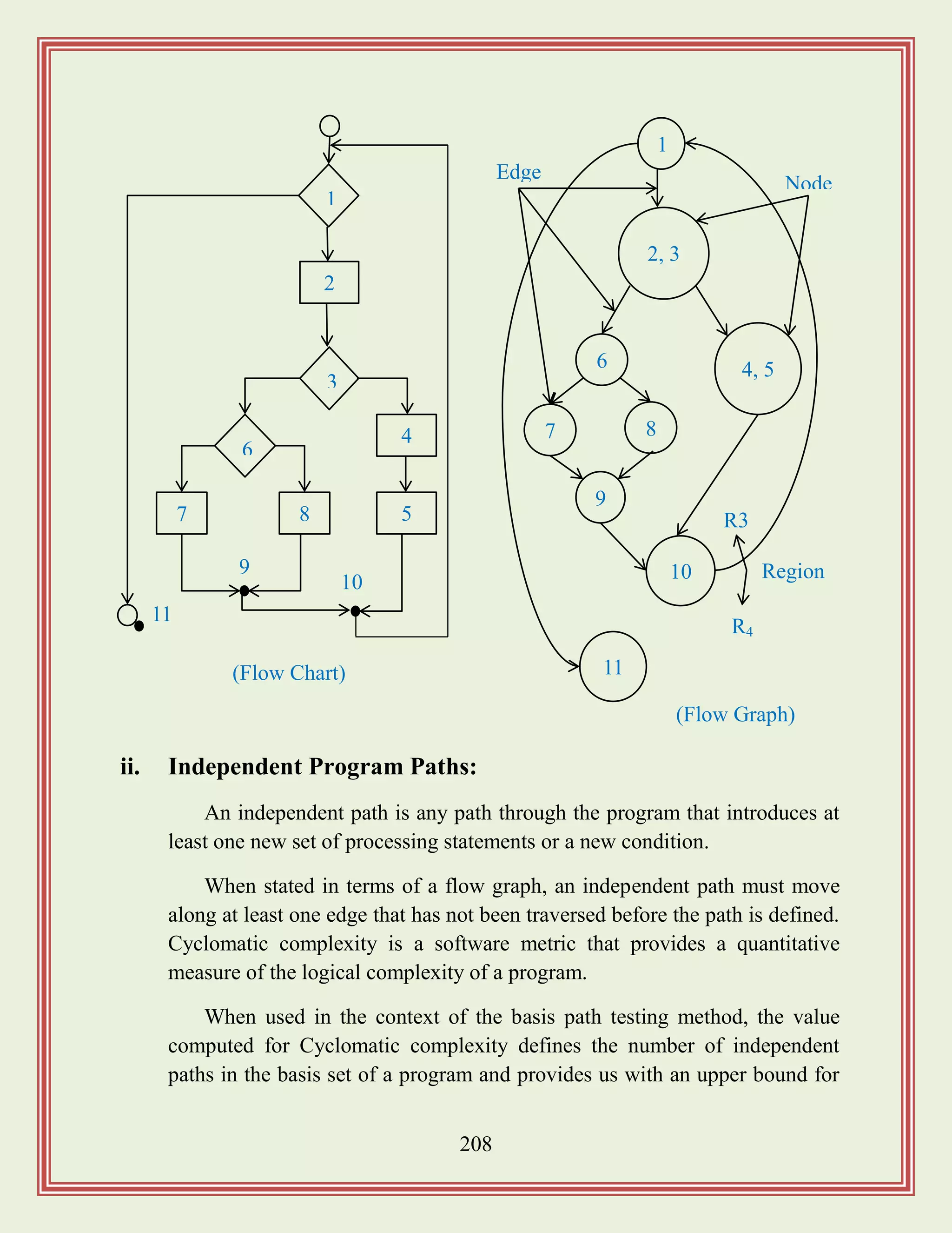
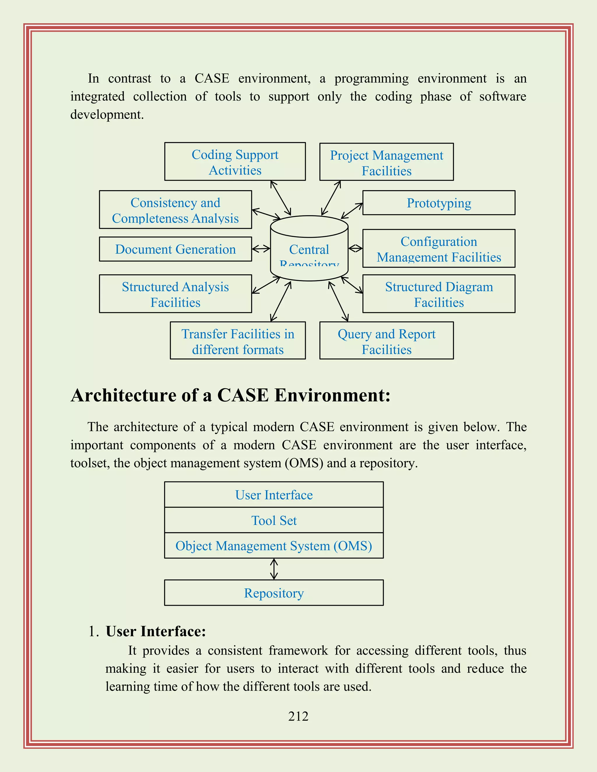
![221
After the cosmetic changes have been carried out the process of extracting code,
design and the requirement specification begins.
In order to extract the design, a full understand of the code is needed. Some
automatic tools can be used to derive the data flow and the control flow diagram
from the code.
Software Maintenance Process Model:
The activities involved in a software maintenance project are not unique and
depend on several factors such as:
i. The extent of modification to the product required.
ii. The resources available to the maintenance team.
iii. The conditions of the existing product.
iv. The expected project risks.
For complex maintenance projects for legacy systems, the software process can
be represented by a reverse engineering cycle followed by a forward engineering
cycle with an emphasis on as much reuse as possible from the existing code and
other documents. There are 2 broad categories of process models is proposed.
Requirement Specification
Design
Module Specification
Code
[Process Model of Revenue Engineering]
Reformat
Program
Assign
Meaningful
names
Simplify
Conditions
Remove
GOTOs
Simplify
Processing](https://image.slidesharecdn.com/softwareengineeringstudymaterials-171005111336/75/Software-engineering-study-materials-222-2048.jpg)

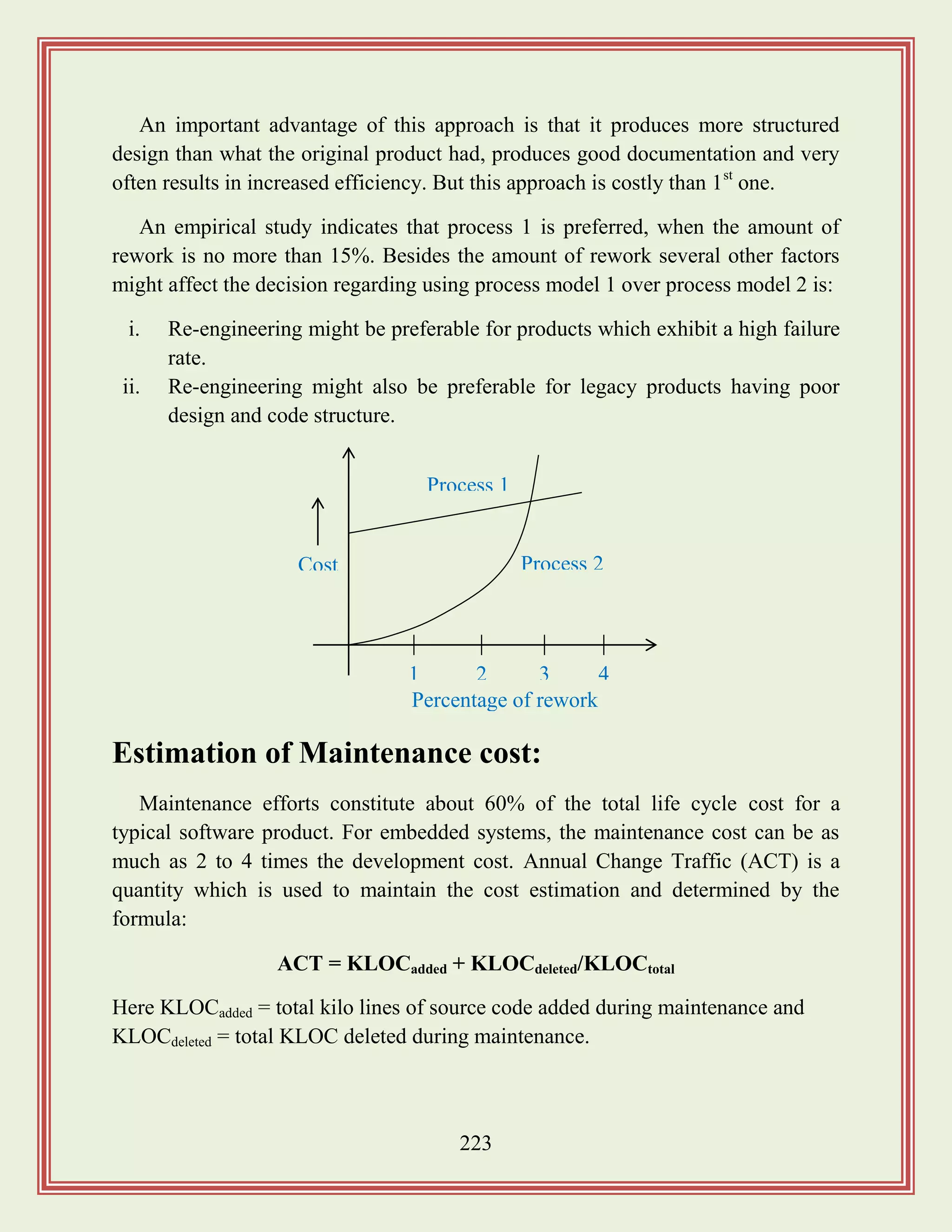
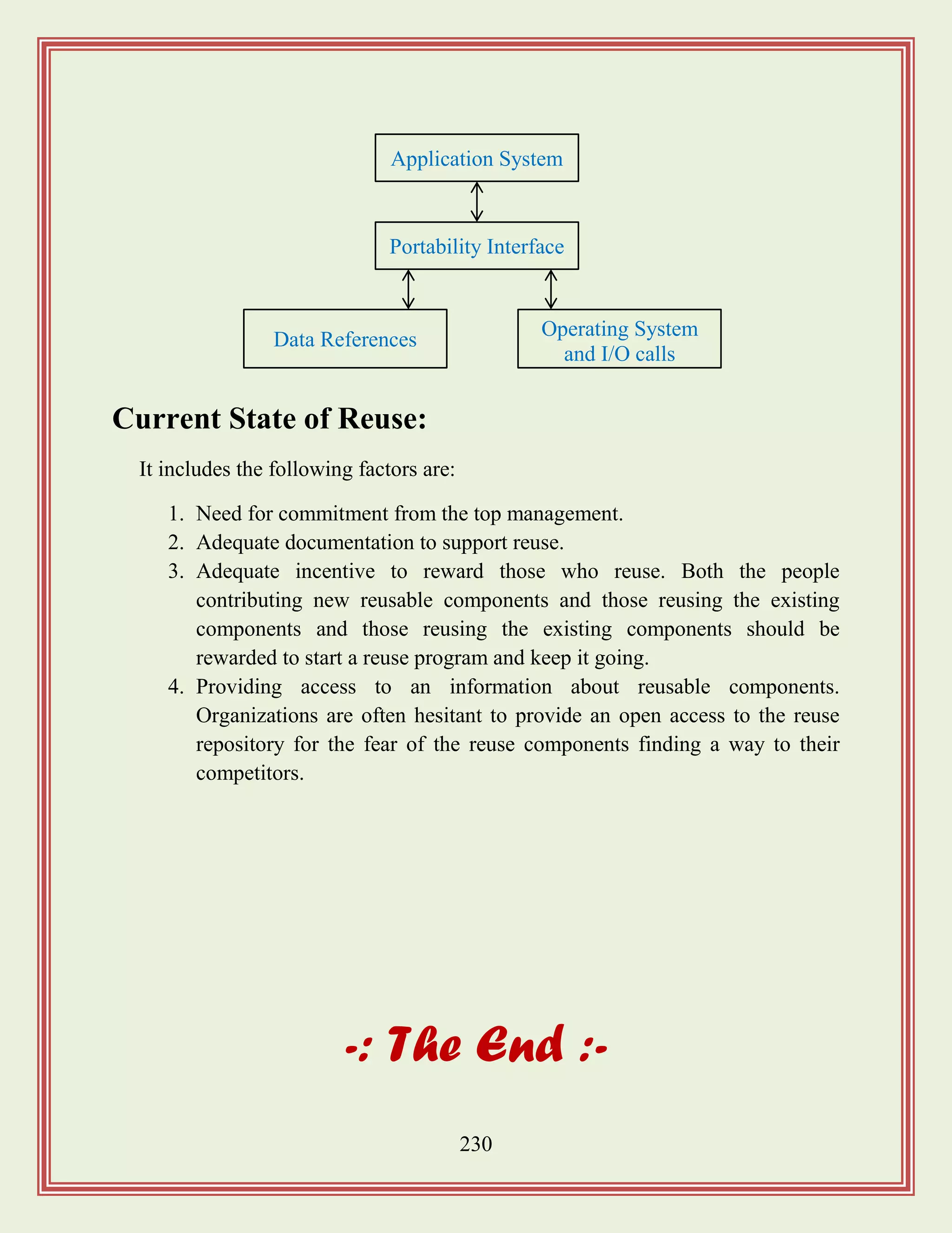
![235
Reliability Growth Modeling:
A reliability growth model is a mathematical model of how reliability improves
as errors are detected and repaired. A reliability growth model can be used to
predict when a particular level of relatively is likely to be attained. Thus, reliability
growth modeling can be used to determine when to stop testing to attain a given
reliability.
Jelinski and Moranda Model:
The simplest reliability growth model is a step function model where it is
assumed that the reliability increases by a constant increment each time an error is
detected and repaired.
This simple model of reliability which implicitly assumes that all errors
contribute equally to reliability growth is highly unrealistic since, we already know
that corrections of different errors contribute differently to reliability growth.
Littlewood and Verall‟s Model:
This model allows for negative reliability growth to reflect the fact that when a
repair is carried out, it may introduce additional errors. It also models the fact that
as errors are repaired, the average improvement in reliability per repair decreases.
It treats an errors contribution to reliability improvement to be an independent
random variable having Gamma distribution. This distribution models the fact that
error corrections with large contributions to reliability growth are removed first.
ROCOF
Time
[Step Function Model of Reliability Growth]](https://image.slidesharecdn.com/softwareengineeringstudymaterials-171005111336/75/Software-engineering-study-materials-236-2048.jpg)