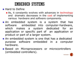
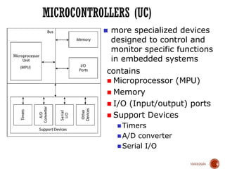
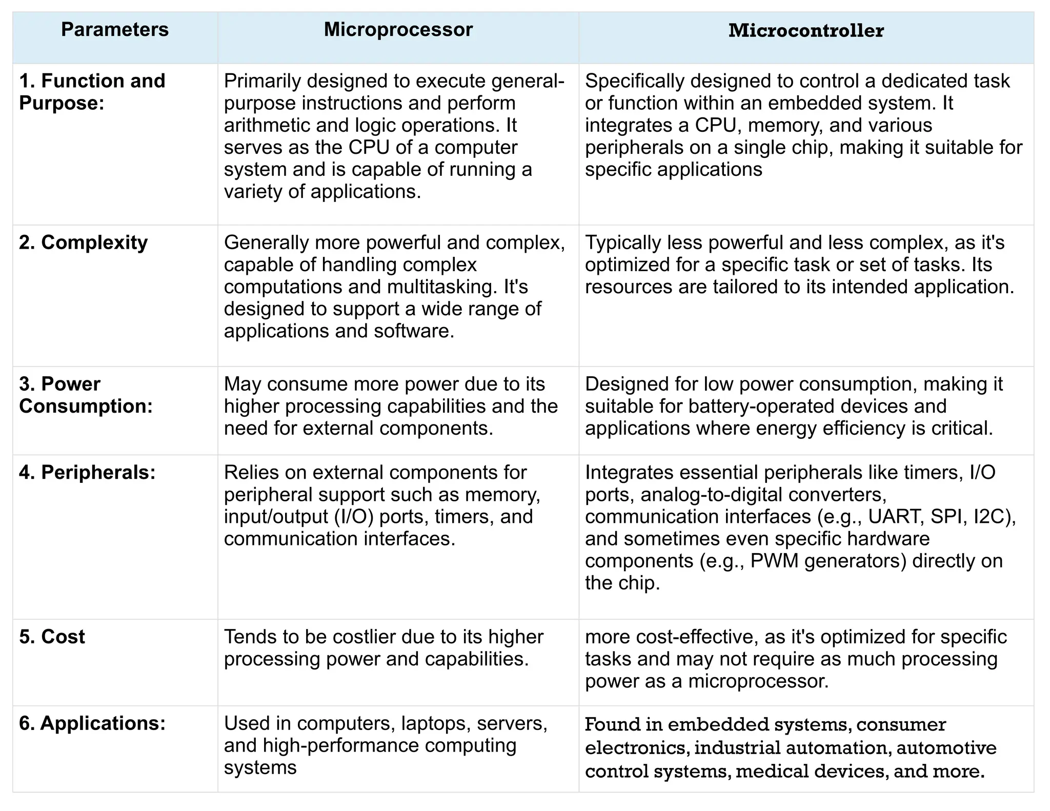
The document provides an introduction to Arduino, its IDE, and the fundamental concepts of microprocessors and microcontrollers within embedded systems. It discusses the differences between microprocessors and microcontrollers, the roles of embedded systems in various applications, and the advantages of using open-source platforms like Arduino for ease of use and innovation. Additionally, it details the Arduino IDE's features, programming environment, and the basics of variable declaration within the programming context.


![10/03/2024
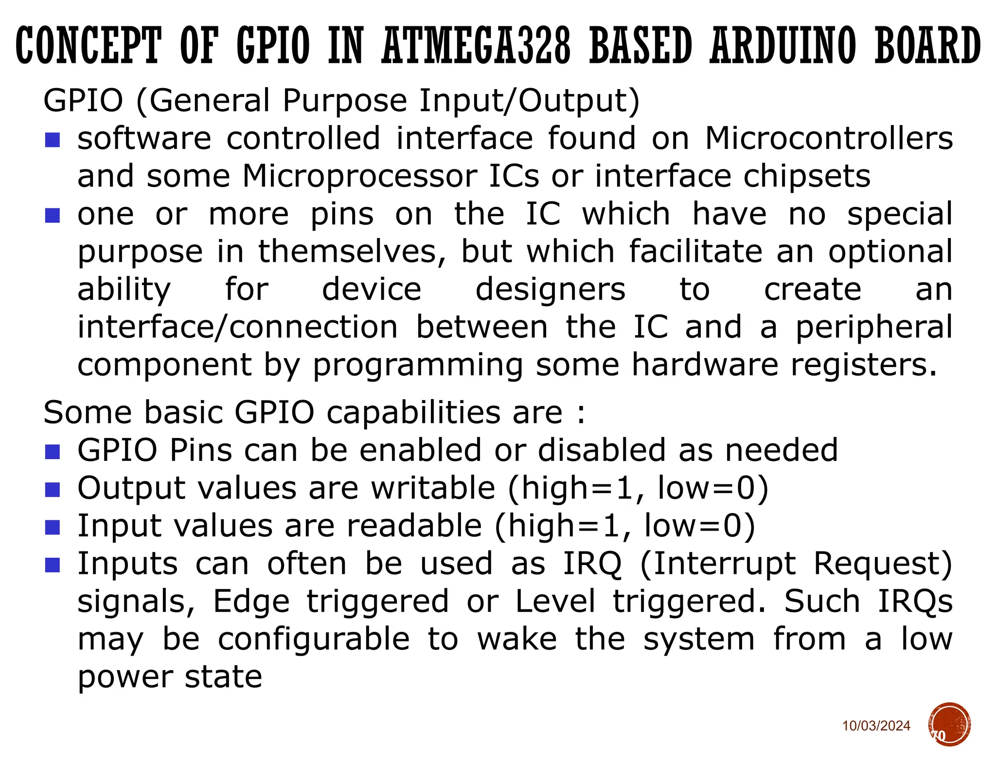
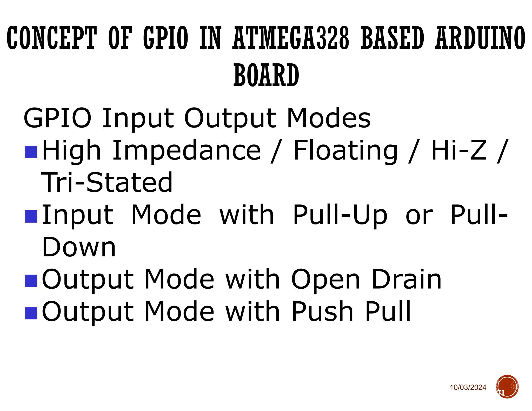
CONCEPT OF GPIO IN ATMEGA328 BASED ARDUINO BOARD
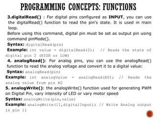
75
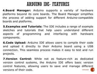
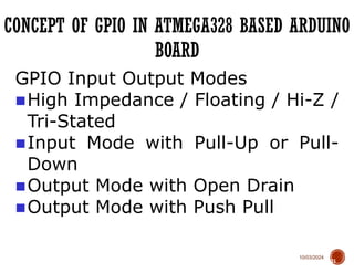
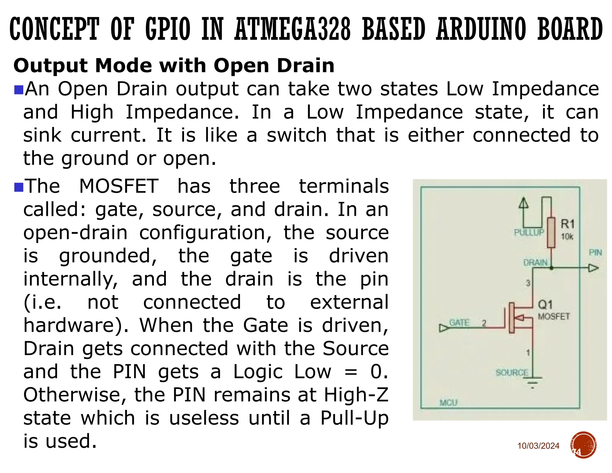
Output Mode with Push Pull
A Push-Pull output is capable of both sourcing and sinking
current.
■When the top transistor [PMOS] will
be activated, the output PIN will be
HIGH and act as a Source. When the
NMOS below will be on, the output
PIN is driven LOW and act as a Sink.
It is a complementary logic and only
once MOS will be activated at a time.](https://image.slidesharecdn.com/unit1introductiontoarduino1-241003065259-b34a429a/85/Unit-1-Introduction-to-Arduino-Board-pptx-75-320.jpg)


![10/03/2024
CONCEPT OF GPIO IN ATMEGA328 BASED ARDUINO BOARD
75
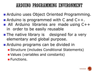
Output Mode with Push Pull
A Push-Pull output is capable of both sourcing and sinking
current.
■When the top transistor [PMOS] will
be activated, the output PIN will be
HIGH and act as a Source. When the
NMOS below will be on, the output
PIN is driven LOW and act as a Sink.
It is a complementary logic and only
once MOS will be activated at a time.](https://image.slidesharecdn.com/unit1introductiontoarduino1-241003065259-b34a429a/75/Unit-1-Introduction-to-Arduino-Board-pptx-75-2048.jpg)


