Download to read offline


![7
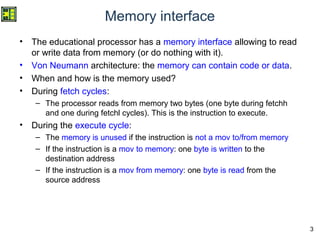
Accessing the memory
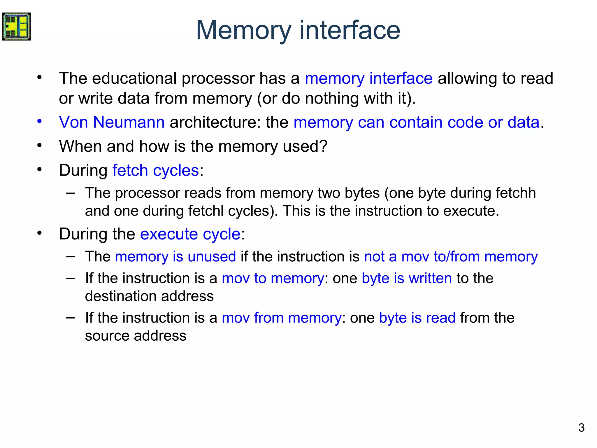
• In the UoS processor, the memory can only be accessed
by “mov” instruction
• Reminder: mov dst, src
Instructions instruction(15..8) Instruction(7..0)
Move Opcode dd#m sd#m dreg
(rn)
src (i or rm)
mov rn, rm 0 0 0 0 0 0 r r - - - - - - r r
mov rn, i 0 0 0 1 0 0 r r i i i i i i i i
mov rn, [rm] 0 0 0 0 0 1 r r - - - - - - r r
mov rn, [i] 0 0 0 1 0 1 r r i i i i i i i i
mov [rn], rm 0 0 0 0 1 0 r r - - - - - - r r
mov [rn], i 0 0 0 1 1 0 r r i i i i i i i i
IR /](https://image.slidesharecdn.com/w93assemblermemoryaccess-171205212204/85/W9_3-UoS-Educational-Processor-Assembler-Memory-Access-7-320.jpg)
![8
Reading data from a memory location
• Move from memory location can be done with immediate or register
address.
• Immediate address: mov ra,[07h]
– Reads the data at address 07h and puts it into register ra
• Register address: mov ra,[rb]
– Reads the data at address rb and puts it into register ra.
– For example, if rb=09, it reads data at address 09 and puts it into ra
Instructions instruction(15..8) Instruction(7..0)
Move Opcode dd#m sd#m dreg
(rn)
src (i or rm)
mov rn, [rm] 0 0 0 0 0 1 r r - - - - - - r r
mov rn, [i] 0 0 0 1 0 1 r r i i i i i i i i
IR /](https://image.slidesharecdn.com/w93assemblermemoryaccess-171205212204/85/W9_3-UoS-Educational-Processor-Assembler-Memory-Access-8-320.jpg)
![9
Reading data from a memory location
mov ra,[07h]
• When executing this instruction (exec
cycle):
– Control unit has put address (07) on
“ram_address”
– The memory is asynchronous for reads
and the value F1h is placed on the
memory output (ram_datard)
– Control unit enables a register file write.
It selects register RA for write. It selects
ram_datard as the data to write.
– On the rising edge in the exec cycle, the
value F1 (coming from the RAM) is thus
stored in RA.
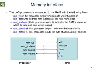
Address Data
00 14
01 07
02 ??
03 ??
04 ??
05 ??
06 ??
07 F1
08 ??
09 DE
0A ??
0B ??
0C ??
0D ??
.. ..
mov ra,[07]
F1 is at
address 07](https://image.slidesharecdn.com/w93assemblermemoryaccess-171205212204/85/W9_3-UoS-Educational-Processor-Assembler-Memory-Access-9-320.jpg)
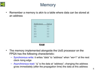
![10
Reading data from a memory location
PC Adr Data Instr RA RB RC
RD
0 0 0 0
-> 00 1407 mov ra,[07h]
02 ???? ??
04 ???? ??
06 ??F1 ??
08 ??DE ??
0A ???? ??](https://image.slidesharecdn.com/w93assemblermemoryaccess-171205212204/85/W9_3-UoS-Educational-Processor-Assembler-Memory-Access-10-320.jpg)
![11
Reading data from a memory location
PC Adr Data Instr RA RB RC
RD
F1 0 0 0
00 1407 mov ra,[07h]
-> 02 ???? ??
04 ???? ??
06 ??F1 ??
08 ??DE ??
0A ???? ??](https://image.slidesharecdn.com/w93assemblermemoryaccess-171205212204/85/W9_3-UoS-Educational-Processor-Assembler-Memory-Access-11-320.jpg)
![12
Reading data from a memory location
mov rb,09
mov ra,[rb]
• When executing the memory mov
instruction (exec cycle):
– Control unit has put address, which is in
register ra (09) on “ram_address”
– The memory is asynchronous for reads
and the value DEh is placed on the
memory output (ram_datard)
– Control unit enables a register file write.
It selects register a for write. It selects
ram_datard as the data to write.
– On the rising edge in the exec cycle, the
value F1 (coming from the RAM) is thus
stored in RA.
Address Data
00 11
01 09
02 04
03 01
04 ??
05 ??
06 ??
07 F1
08 ??
09 DE
0A ??
0B ??
0C ??
0D ??
.. ..
mov rb,09
DE is at
address 09
mov ra,[rb]](https://image.slidesharecdn.com/w93assemblermemoryaccess-171205212204/85/W9_3-UoS-Educational-Processor-Assembler-Memory-Access-12-320.jpg)
![13
Reading data from a memory location
PC Adr Data Instr RA RB RC
RD
0 0 0 0
-> 00 1109 mov rb,09 h
02 0401 mov ra,[rb]
04 ???? ??
06 ??F1 ??
08 ??DE ??
0A ???? ??](https://image.slidesharecdn.com/w93assemblermemoryaccess-171205212204/85/W9_3-UoS-Educational-Processor-Assembler-Memory-Access-13-320.jpg)
![14
Reading data from a memory location
PC Adr Data Instr RA RB RC
RD
0 09 0 0
00 1109 mov rb,09 h
-> 02 0401 mov ra,[rb]
04 ???? ??
06 ??F1 ??
08 ??DE ??
0A ???? ??](https://image.slidesharecdn.com/w93assemblermemoryaccess-171205212204/85/W9_3-UoS-Educational-Processor-Assembler-Memory-Access-14-320.jpg)
![15
Reading data from a memory location
PC Adr Data Instr RA RB RC
RD
DE 09 0 0
00 1109 mov rb,09 h
02 0401 mov ra,[rb]
-> 04 ???? ??
06 ??F1 ??
08 ??DE ??
0A ???? ??](https://image.slidesharecdn.com/w93assemblermemoryaccess-171205212204/85/W9_3-UoS-Educational-Processor-Assembler-Memory-Access-15-320.jpg)
![16
Writing data to a memory location
• Move to memory location can be done only with register address.
The source can be a register or immediate.
– This is due to the choice of instruction encoding; with 16 bit instructions
the UoS processor cannot have immediate memory destination and
immediate source! A different encoding would be required.
• Immediate source: mov [ra],07h
– Writes 07h to the address ra.
– For example, if ra=09, then 07h is written to addres 09h.
• Register source: mov [ra],rb
– Writes the data rb to the addres ra.
Instructions instruction(15..8) Instruction(7..0)
Move Opcode dd#m sd#m dreg
(rn)
src (i or rm)
mov [rn], rm 0 0 0 0 1 0 r r - - - - - - r r
mov [rn], i 0 0 0 1 1 0 r r i i i i i i i i
IR /](https://image.slidesharecdn.com/w93assemblermemoryaccess-171205212204/85/W9_3-UoS-Educational-Processor-Assembler-Memory-Access-16-320.jpg)
![17
Writing data to a memory location
mov ra,09h
mov [ra],07
• When executing this instruction (exec
cycle):
– Control unit has put address (09) on
“ram_address”
– Control unit has put data (07) on
ram_datawr.
– Control unit has enabled ram write
“ram_we=1”
– The memory is synchronous for writes.
On the rising edge in the exec cycle, the
value 07 is stored to address 09.
Address Data
00 10
01 09
02 18
03 07
04 ??
05 ??
06 ??
07 ??
08 ??
09 ??
0A ??
0B ??
0C ??
0D ??
.. ..
mov ra,09
mov [ra],07](https://image.slidesharecdn.com/w93assemblermemoryaccess-171205212204/85/W9_3-UoS-Educational-Processor-Assembler-Memory-Access-17-320.jpg)
![18
Writing data to a memory location
PC Adr Data Instr RA RB RC
RD
0 0 0 0
-> 00 1000 mov ra,09h
02 1807 mov [ra],07
04 ???? ??
06 ???? ??
08 ???? ??
0A ???? ??](https://image.slidesharecdn.com/w93assemblermemoryaccess-171205212204/85/W9_3-UoS-Educational-Processor-Assembler-Memory-Access-18-320.jpg)
![19
Writing data to a memory location
PC Adr Data Instr RA RB RC
RD
09 0 0 0
00 1000 mov ra,09h
-> 02 1807 mov [ra],07
04 ????
06 ????
08 ????
0A ????](https://image.slidesharecdn.com/w93assemblermemoryaccess-171205212204/85/W9_3-UoS-Educational-Processor-Assembler-Memory-Access-19-320.jpg)
![20
Writing data to a memory location
PC Adr Data Instr RA RB RC
RD
09 0 0 0
00 1000 mov ra,09h
02 1807 mov [ra],07
-> 04 ????
06 ????
08 ??07
0A ????](https://image.slidesharecdn.com/w93assemblermemoryaccess-171205212204/85/W9_3-UoS-Educational-Processor-Assembler-Memory-Access-20-320.jpg)
![21
Writing data to a memory location
mov rb,08h
mov ra,FCh
mov [rb],ra
• When executing this instruction (exec
cycle):
– Control unit has put address (08) on
“ram_address”
– Control unit has put data (FC) on
ram_datawr.
– Control unit has enabled ram write
“ram_we=1”
– The memory is synchronous for writes.
On the rising edge in the exec cycle, the
value FC is stored to address 08.
Address Data
00 11
01 08
02 10
03 FC
04 09
05 00
06 ??
07 ??
08 ??
09 ??
0A ??
0B ??
0C ??
0D ??
.. ..
mov rb,08
mov ra,FC
mov [rb],ra](https://image.slidesharecdn.com/w93assemblermemoryaccess-171205212204/85/W9_3-UoS-Educational-Processor-Assembler-Memory-Access-21-320.jpg)
![22
Writing data to a memory location
PC Adr Data Instr RA RB RC
RD
0 0 0 0
-> 00 1108 mov rb,08h
02 10FC mov ra,FCh
04 0900 mov [rb],ra
06 ???? ??
08 ???? ??
0A ???? ??](https://image.slidesharecdn.com/w93assemblermemoryaccess-171205212204/85/W9_3-UoS-Educational-Processor-Assembler-Memory-Access-22-320.jpg)
![23
Writing data to a memory location
PC Adr Data Instr RA RB RC
RD
0 08 0 0
00 1108 mov rb,08h
-> 02 10FC mov ra,FCh
04 0900 mov [rb],ra
06 ???? ??
08 ???? ??
0A ???? ??](https://image.slidesharecdn.com/w93assemblermemoryaccess-171205212204/85/W9_3-UoS-Educational-Processor-Assembler-Memory-Access-23-320.jpg)
![24
Writing data to a memory location
PC Adr Data Instr RA RB RC
RD
FC 08 0 0
00 1108 mov rb,08h
02 10FC mov ra,FCh
-> 04 0900 mov [rb],ra
06 ???? ??
08 ???? ??
0A ???? ??](https://image.slidesharecdn.com/w93assemblermemoryaccess-171205212204/85/W9_3-UoS-Educational-Processor-Assembler-Memory-Access-24-320.jpg)
![25
Writing data to a memory location
PC Adr Data Instr RA RB RC
RD
FC 08 0 0
00 1108 mov rb,08h
02 10FC mov ra,FCh
04 0900 mov [rb],ra
-> 06 ???? ??
08 FC?? ??
0A ???? ??](https://image.slidesharecdn.com/w93assemblermemoryaccess-171205212204/85/W9_3-UoS-Educational-Processor-Assembler-Memory-Access-25-320.jpg)
![26
ALU operations with memory operands
• In the UoS processor, ALU operations cannot be directly
performed on memory data. Instead:
– Read the operands from memory and put them in registers
– Perform the ALU operation on the registers
– Write the result register to the destination memory
• Example: read data at address 1C and 1D, add them
together, and store the result at address 1C
mov ra,1Ch
mov rb,[ra]
mov rc,[1Dh]
add rb,rc
mov [ra],rb](https://image.slidesharecdn.com/w93assemblermemoryaccess-171205212204/85/W9_3-UoS-Educational-Processor-Assembler-Memory-Access-26-320.jpg)
![27
ALU operations with memory operands
• Other processor architectures may have ALU operations
allowing memory operands.
• This is the case with Intel/AMD x86. The following are
some of the available possibilities:
add reg,reg
add reg,[mem]
add [mem],reg
add reg,imm
add [mem],imm](https://image.slidesharecdn.com/w93assemblermemoryaccess-171205212204/85/W9_3-UoS-Educational-Processor-Assembler-Memory-Access-27-320.jpg)
![28
Mixing code and data in memory
• Von Neumann: code and
data can be mixed!
• It is up to the programmer
(or the compiler) to know
where to place data and
code in the memory.
• Only constraint: the first
instruction is at address 0
• This program iterates
between 06-10 according
to the value at address 3
Address Data
00 B0
01 06
02 ??
03 05
04 ??
05 ??
06 14
07 03
08 D0
09 00
0A D0
0B FF
0C 34
0D 01
0E 54
0F 00
10 B9
11 08
.. ??
.. ??
xx B0
xx+1 xx
jmp 06h
mov ra,[03h]
out 00h
out FFh
sub ra,1
cmp ra,0h
jne 08h
This is not executed.
It is either garbage, or
data.
jmp xx](https://image.slidesharecdn.com/w93assemblermemoryaccess-171205212204/85/W9_3-UoS-Educational-Processor-Assembler-Memory-Access-28-320.jpg)
![34
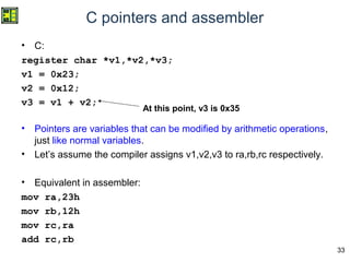
C pointers and assembler
• In addition, pointers can be used to read or write
memory locations.
• Writing byte to address v: *v = x;
– Maps to instructions: mov [rn],i or mov [rn],rm
• Reading byte from address v: x = *v;
– Maps to instruction: mov rn,[i] or mov rn,[rm]](https://image.slidesharecdn.com/w93assemblermemoryaccess-171205212204/85/W9_3-UoS-Educational-Processor-Assembler-Memory-Access-34-320.jpg)
![35
C pointers and assembler: writing memory
• Example:
register char *v1,*v2;
v1 = 0x0B;
v2 = 0x0D;
*v1 = 0xFE;
*v2 = 0x3F;
• Assembler:
mov ra,0Bh
mov rb,0Dh
mov [ra],FEh
mov [rb],3Fh
Here writing to memory location 0B and 0D
Here writing to memory location 0B and 0D](https://image.slidesharecdn.com/w93assemblermemoryaccess-171205212204/85/W9_3-UoS-Educational-Processor-Assembler-Memory-Access-35-320.jpg)
![36
C pointers and assembler: writing memory
PC Adr Data Instr RA RB RC
RD
0 0 0 0
-> 00 100B mov ra,0Bh
02 110D mov rb,0Dh
04 18FE mov [ra],FEh
06 193F mov [rb],3Fh
08 ???? ??
0A ???? ??
0C ???? ??
0E ???? ??](https://image.slidesharecdn.com/w93assemblermemoryaccess-171205212204/85/W9_3-UoS-Educational-Processor-Assembler-Memory-Access-36-320.jpg)
![37
C pointers and assembler: writing memory
PC Adr Data Instr RA RB RC
RD
0B 0 0 0
00 100B mov ra,0Bh
-> 02 110D mov rb,0Dh
04 18FE mov [ra],FEh
06 193F mov [rb],3Fh
08 ???? ??
0A ???? ??
0C ???? ??
0E ???? ??](https://image.slidesharecdn.com/w93assemblermemoryaccess-171205212204/85/W9_3-UoS-Educational-Processor-Assembler-Memory-Access-37-320.jpg)
![38
C pointers and assembler: writing memory
PC Adr Data Instr RA RB RC
RD
0B 0D 0 0
00 100B mov ra,0Bh
02 110D mov rb,0Dh
-> 04 18FE mov [ra],FEh
06 193F mov [rb],3Fh
08 ???? ??
0A ???? ??
0C ???? ??
0E ???? ??](https://image.slidesharecdn.com/w93assemblermemoryaccess-171205212204/85/W9_3-UoS-Educational-Processor-Assembler-Memory-Access-38-320.jpg)
![39
C pointers and assembler: writing memory
PC Adr Data Instr RA RB RC
RD
0B 0D 0 0
00 100B mov ra,0Bh
02 110D mov rb,0Dh
04 18FE mov [ra],FEh
-> 06 193F mov [rb],3Fh
08 ???? ??
0A ??FE ??
0C ???? ??
0E ???? ??](https://image.slidesharecdn.com/w93assemblermemoryaccess-171205212204/85/W9_3-UoS-Educational-Processor-Assembler-Memory-Access-39-320.jpg)
![40
C pointers and assembler: writing memory
PC Adr Data Instr RA RB RC
RD
0B 0D 0 0
00 100B mov ra,0Bh
02 110D mov rb,0Dh
04 18FE mov [ra],FEh
06 193F mov [rb],3Fh
-> 08 ???? ??
0A ??FE ??
0C ??3F ??
0E ???? ??](https://image.slidesharecdn.com/w93assemblermemoryaccess-171205212204/85/W9_3-UoS-Educational-Processor-Assembler-Memory-Access-40-320.jpg)
![41
C pointers and assembler: reading memory
• Example:
register char *v1;
register char v2;
v1 = 0x0B;
v2 = *v1;
• Assembler:
mov ra,0Bh
mov rb,[ra]
Here reading from memory location 0B
Here reading from memory location 0B](https://image.slidesharecdn.com/w93assemblermemoryaccess-171205212204/85/W9_3-UoS-Educational-Processor-Assembler-Memory-Access-41-320.jpg)
![42
C pointers and assembler: reading memory
PC Adr Data Instr RA RB RC
RD
0 0 0 0
-> 00 100B mov ra,0Bh
02 0500 mov rb,[ra]
04 ???? ??
06 ???? ??
08 ???? ??
0A ??DB ??
0C ???? ??
0E ???? ??](https://image.slidesharecdn.com/w93assemblermemoryaccess-171205212204/85/W9_3-UoS-Educational-Processor-Assembler-Memory-Access-42-320.jpg)
![43
C pointers and assembler: reading memory
PC Adr Data Instr RA RB RC
RD
0B 0 0 0
00 100B mov ra,0Bh
-> 02 0500 mov rb,[ra]
04 ???? ??
06 ???? ??
08 ???? ??
0A ??DB ??
0C ???? ??
0E ???? ??](https://image.slidesharecdn.com/w93assemblermemoryaccess-171205212204/85/W9_3-UoS-Educational-Processor-Assembler-Memory-Access-43-320.jpg)
![44
C pointers and assembler: reading memory
PC Adr Data Instr RA RB RC
RD
0B DB 0 0
00 100B mov ra,0Bh
02 0500 mov rb,[ra]
-> 04 ???? ??
06 ???? ??
08 ???? ??
0A ??DB ??
0C ???? ??
0E ???? ??](https://image.slidesharecdn.com/w93assemblermemoryaccess-171205212204/85/W9_3-UoS-Educational-Processor-Assembler-Memory-Access-44-320.jpg)

![7
Accessing the memory
• In the UoS processor, the memory can only be accessed
by “mov” instruction
• Reminder: mov dst, src
Instructions instruction(15..8) Instruction(7..0)
Move Opcode dd#m sd#m dreg
(rn)
src (i or rm)
mov rn, rm 0 0 0 0 0 0 r r - - - - - - r r
mov rn, i 0 0 0 1 0 0 r r i i i i i i i i
mov rn, [rm] 0 0 0 0 0 1 r r - - - - - - r r
mov rn, [i] 0 0 0 1 0 1 r r i i i i i i i i
mov [rn], rm 0 0 0 0 1 0 r r - - - - - - r r
mov [rn], i 0 0 0 1 1 0 r r i i i i i i i i
IR /](https://image.slidesharecdn.com/w93assemblermemoryaccess-171205212204/75/W9_3-UoS-Educational-Processor-Assembler-Memory-Access-7-2048.jpg)
![8
Reading data from a memory location
• Move from memory location can be done with immediate or register
address.
• Immediate address: mov ra,[07h]
– Reads the data at address 07h and puts it into register ra
• Register address: mov ra,[rb]
– Reads the data at address rb and puts it into register ra.
– For example, if rb=09, it reads data at address 09 and puts it into ra
Instructions instruction(15..8) Instruction(7..0)
Move Opcode dd#m sd#m dreg
(rn)
src (i or rm)
mov rn, [rm] 0 0 0 0 0 1 r r - - - - - - r r
mov rn, [i] 0 0 0 1 0 1 r r i i i i i i i i
IR /](https://image.slidesharecdn.com/w93assemblermemoryaccess-171205212204/75/W9_3-UoS-Educational-Processor-Assembler-Memory-Access-8-2048.jpg)
![9
Reading data from a memory location
mov ra,[07h]
• When executing this instruction (exec
cycle):
– Control unit has put address (07) on
“ram_address”
– The memory is asynchronous for reads
and the value F1h is placed on the
memory output (ram_datard)
– Control unit enables a register file write.
It selects register RA for write. It selects
ram_datard as the data to write.
– On the rising edge in the exec cycle, the
value F1 (coming from the RAM) is thus
stored in RA.
Address Data
00 14
01 07
02 ??
03 ??
04 ??
05 ??
06 ??
07 F1
08 ??
09 DE
0A ??
0B ??
0C ??
0D ??
.. ..
mov ra,[07]
F1 is at
address 07](https://image.slidesharecdn.com/w93assemblermemoryaccess-171205212204/75/W9_3-UoS-Educational-Processor-Assembler-Memory-Access-9-2048.jpg)
![10
Reading data from a memory location
PC Adr Data Instr RA RB RC
RD
0 0 0 0
-> 00 1407 mov ra,[07h]
02 ???? ??
04 ???? ??
06 ??F1 ??
08 ??DE ??
0A ???? ??](https://image.slidesharecdn.com/w93assemblermemoryaccess-171205212204/75/W9_3-UoS-Educational-Processor-Assembler-Memory-Access-10-2048.jpg)
![11
Reading data from a memory location
PC Adr Data Instr RA RB RC
RD
F1 0 0 0
00 1407 mov ra,[07h]
-> 02 ???? ??
04 ???? ??
06 ??F1 ??
08 ??DE ??
0A ???? ??](https://image.slidesharecdn.com/w93assemblermemoryaccess-171205212204/75/W9_3-UoS-Educational-Processor-Assembler-Memory-Access-11-2048.jpg)
![12
Reading data from a memory location
mov rb,09
mov ra,[rb]
• When executing the memory mov
instruction (exec cycle):
– Control unit has put address, which is in
register ra (09) on “ram_address”
– The memory is asynchronous for reads
and the value DEh is placed on the
memory output (ram_datard)
– Control unit enables a register file write.
It selects register a for write. It selects
ram_datard as the data to write.
– On the rising edge in the exec cycle, the
value F1 (coming from the RAM) is thus
stored in RA.
Address Data
00 11
01 09
02 04
03 01
04 ??
05 ??
06 ??
07 F1
08 ??
09 DE
0A ??
0B ??
0C ??
0D ??
.. ..
mov rb,09
DE is at
address 09
mov ra,[rb]](https://image.slidesharecdn.com/w93assemblermemoryaccess-171205212204/75/W9_3-UoS-Educational-Processor-Assembler-Memory-Access-12-2048.jpg)
![13
Reading data from a memory location
PC Adr Data Instr RA RB RC
RD
0 0 0 0
-> 00 1109 mov rb,09 h
02 0401 mov ra,[rb]
04 ???? ??
06 ??F1 ??
08 ??DE ??
0A ???? ??](https://image.slidesharecdn.com/w93assemblermemoryaccess-171205212204/75/W9_3-UoS-Educational-Processor-Assembler-Memory-Access-13-2048.jpg)
![14
Reading data from a memory location
PC Adr Data Instr RA RB RC
RD
0 09 0 0
00 1109 mov rb,09 h
-> 02 0401 mov ra,[rb]
04 ???? ??
06 ??F1 ??
08 ??DE ??
0A ???? ??](https://image.slidesharecdn.com/w93assemblermemoryaccess-171205212204/75/W9_3-UoS-Educational-Processor-Assembler-Memory-Access-14-2048.jpg)
![15
Reading data from a memory location
PC Adr Data Instr RA RB RC
RD
DE 09 0 0
00 1109 mov rb,09 h
02 0401 mov ra,[rb]
-> 04 ???? ??
06 ??F1 ??
08 ??DE ??
0A ???? ??](https://image.slidesharecdn.com/w93assemblermemoryaccess-171205212204/75/W9_3-UoS-Educational-Processor-Assembler-Memory-Access-15-2048.jpg)
![16
Writing data to a memory location
• Move to memory location can be done only with register address.
The source can be a register or immediate.
– This is due to the choice of instruction encoding; with 16 bit instructions
the UoS processor cannot have immediate memory destination and
immediate source! A different encoding would be required.
• Immediate source: mov [ra],07h
– Writes 07h to the address ra.
– For example, if ra=09, then 07h is written to addres 09h.
• Register source: mov [ra],rb
– Writes the data rb to the addres ra.
Instructions instruction(15..8) Instruction(7..0)
Move Opcode dd#m sd#m dreg
(rn)
src (i or rm)
mov [rn], rm 0 0 0 0 1 0 r r - - - - - - r r
mov [rn], i 0 0 0 1 1 0 r r i i i i i i i i
IR /](https://image.slidesharecdn.com/w93assemblermemoryaccess-171205212204/75/W9_3-UoS-Educational-Processor-Assembler-Memory-Access-16-2048.jpg)
![17
Writing data to a memory location
mov ra,09h
mov [ra],07
• When executing this instruction (exec
cycle):
– Control unit has put address (09) on
“ram_address”
– Control unit has put data (07) on
ram_datawr.
– Control unit has enabled ram write
“ram_we=1”
– The memory is synchronous for writes.
On the rising edge in the exec cycle, the
value 07 is stored to address 09.
Address Data
00 10
01 09
02 18
03 07
04 ??
05 ??
06 ??
07 ??
08 ??
09 ??
0A ??
0B ??
0C ??
0D ??
.. ..
mov ra,09
mov [ra],07](https://image.slidesharecdn.com/w93assemblermemoryaccess-171205212204/75/W9_3-UoS-Educational-Processor-Assembler-Memory-Access-17-2048.jpg)
![18
Writing data to a memory location
PC Adr Data Instr RA RB RC
RD
0 0 0 0
-> 00 1000 mov ra,09h
02 1807 mov [ra],07
04 ???? ??
06 ???? ??
08 ???? ??
0A ???? ??](https://image.slidesharecdn.com/w93assemblermemoryaccess-171205212204/75/W9_3-UoS-Educational-Processor-Assembler-Memory-Access-18-2048.jpg)
![19
Writing data to a memory location
PC Adr Data Instr RA RB RC
RD
09 0 0 0
00 1000 mov ra,09h
-> 02 1807 mov [ra],07
04 ????
06 ????
08 ????
0A ????](https://image.slidesharecdn.com/w93assemblermemoryaccess-171205212204/75/W9_3-UoS-Educational-Processor-Assembler-Memory-Access-19-2048.jpg)
![20
Writing data to a memory location
PC Adr Data Instr RA RB RC
RD
09 0 0 0
00 1000 mov ra,09h
02 1807 mov [ra],07
-> 04 ????
06 ????
08 ??07
0A ????](https://image.slidesharecdn.com/w93assemblermemoryaccess-171205212204/75/W9_3-UoS-Educational-Processor-Assembler-Memory-Access-20-2048.jpg)
![21
Writing data to a memory location
mov rb,08h
mov ra,FCh
mov [rb],ra
• When executing this instruction (exec
cycle):
– Control unit has put address (08) on
“ram_address”
– Control unit has put data (FC) on
ram_datawr.
– Control unit has enabled ram write
“ram_we=1”
– The memory is synchronous for writes.
On the rising edge in the exec cycle, the
value FC is stored to address 08.
Address Data
00 11
01 08
02 10
03 FC
04 09
05 00
06 ??
07 ??
08 ??
09 ??
0A ??
0B ??
0C ??
0D ??
.. ..
mov rb,08
mov ra,FC
mov [rb],ra](https://image.slidesharecdn.com/w93assemblermemoryaccess-171205212204/75/W9_3-UoS-Educational-Processor-Assembler-Memory-Access-21-2048.jpg)
![22
Writing data to a memory location
PC Adr Data Instr RA RB RC
RD
0 0 0 0
-> 00 1108 mov rb,08h
02 10FC mov ra,FCh
04 0900 mov [rb],ra
06 ???? ??
08 ???? ??
0A ???? ??](https://image.slidesharecdn.com/w93assemblermemoryaccess-171205212204/75/W9_3-UoS-Educational-Processor-Assembler-Memory-Access-22-2048.jpg)
![23
Writing data to a memory location
PC Adr Data Instr RA RB RC
RD
0 08 0 0
00 1108 mov rb,08h
-> 02 10FC mov ra,FCh
04 0900 mov [rb],ra
06 ???? ??
08 ???? ??
0A ???? ??](https://image.slidesharecdn.com/w93assemblermemoryaccess-171205212204/75/W9_3-UoS-Educational-Processor-Assembler-Memory-Access-23-2048.jpg)
![24
Writing data to a memory location
PC Adr Data Instr RA RB RC
RD
FC 08 0 0
00 1108 mov rb,08h
02 10FC mov ra,FCh
-> 04 0900 mov [rb],ra
06 ???? ??
08 ???? ??
0A ???? ??](https://image.slidesharecdn.com/w93assemblermemoryaccess-171205212204/75/W9_3-UoS-Educational-Processor-Assembler-Memory-Access-24-2048.jpg)
![25
Writing data to a memory location
PC Adr Data Instr RA RB RC
RD
FC 08 0 0
00 1108 mov rb,08h
02 10FC mov ra,FCh
04 0900 mov [rb],ra
-> 06 ???? ??
08 FC?? ??
0A ???? ??](https://image.slidesharecdn.com/w93assemblermemoryaccess-171205212204/75/W9_3-UoS-Educational-Processor-Assembler-Memory-Access-25-2048.jpg)
![26
ALU operations with memory operands
• In the UoS processor, ALU operations cannot be directly
performed on memory data. Instead:
– Read the operands from memory and put them in registers
– Perform the ALU operation on the registers
– Write the result register to the destination memory
• Example: read data at address 1C and 1D, add them
together, and store the result at address 1C
mov ra,1Ch
mov rb,[ra]
mov rc,[1Dh]
add rb,rc
mov [ra],rb](https://image.slidesharecdn.com/w93assemblermemoryaccess-171205212204/75/W9_3-UoS-Educational-Processor-Assembler-Memory-Access-26-2048.jpg)
![27
ALU operations with memory operands
• Other processor architectures may have ALU operations
allowing memory operands.
• This is the case with Intel/AMD x86. The following are
some of the available possibilities:
add reg,reg
add reg,[mem]
add [mem],reg
add reg,imm
add [mem],imm](https://image.slidesharecdn.com/w93assemblermemoryaccess-171205212204/75/W9_3-UoS-Educational-Processor-Assembler-Memory-Access-27-2048.jpg)
![28
Mixing code and data in memory
• Von Neumann: code and
data can be mixed!
• It is up to the programmer
(or the compiler) to know
where to place data and
code in the memory.
• Only constraint: the first
instruction is at address 0
• This program iterates
between 06-10 according
to the value at address 3
Address Data
00 B0
01 06
02 ??
03 05
04 ??
05 ??
06 14
07 03
08 D0
09 00
0A D0
0B FF
0C 34
0D 01
0E 54
0F 00
10 B9
11 08
.. ??
.. ??
xx B0
xx+1 xx
jmp 06h
mov ra,[03h]
out 00h
out FFh
sub ra,1
cmp ra,0h
jne 08h
This is not executed.
It is either garbage, or
data.
jmp xx](https://image.slidesharecdn.com/w93assemblermemoryaccess-171205212204/75/W9_3-UoS-Educational-Processor-Assembler-Memory-Access-28-2048.jpg)


![34
C pointers and assembler
• In addition, pointers can be used to read or write
memory locations.
• Writing byte to address v: *v = x;
– Maps to instructions: mov [rn],i or mov [rn],rm
• Reading byte from address v: x = *v;
– Maps to instruction: mov rn,[i] or mov rn,[rm]](https://image.slidesharecdn.com/w93assemblermemoryaccess-171205212204/75/W9_3-UoS-Educational-Processor-Assembler-Memory-Access-34-2048.jpg)
![35
C pointers and assembler: writing memory
• Example:
register char *v1,*v2;
v1 = 0x0B;
v2 = 0x0D;
*v1 = 0xFE;
*v2 = 0x3F;
• Assembler:
mov ra,0Bh
mov rb,0Dh
mov [ra],FEh
mov [rb],3Fh
Here writing to memory location 0B and 0D
Here writing to memory location 0B and 0D](https://image.slidesharecdn.com/w93assemblermemoryaccess-171205212204/75/W9_3-UoS-Educational-Processor-Assembler-Memory-Access-35-2048.jpg)
![36
C pointers and assembler: writing memory
PC Adr Data Instr RA RB RC
RD
0 0 0 0
-> 00 100B mov ra,0Bh
02 110D mov rb,0Dh
04 18FE mov [ra],FEh
06 193F mov [rb],3Fh
08 ???? ??
0A ???? ??
0C ???? ??
0E ???? ??](https://image.slidesharecdn.com/w93assemblermemoryaccess-171205212204/75/W9_3-UoS-Educational-Processor-Assembler-Memory-Access-36-2048.jpg)
![37
C pointers and assembler: writing memory
PC Adr Data Instr RA RB RC
RD
0B 0 0 0
00 100B mov ra,0Bh
-> 02 110D mov rb,0Dh
04 18FE mov [ra],FEh
06 193F mov [rb],3Fh
08 ???? ??
0A ???? ??
0C ???? ??
0E ???? ??](https://image.slidesharecdn.com/w93assemblermemoryaccess-171205212204/75/W9_3-UoS-Educational-Processor-Assembler-Memory-Access-37-2048.jpg)
![38
C pointers and assembler: writing memory
PC Adr Data Instr RA RB RC
RD
0B 0D 0 0
00 100B mov ra,0Bh
02 110D mov rb,0Dh
-> 04 18FE mov [ra],FEh
06 193F mov [rb],3Fh
08 ???? ??
0A ???? ??
0C ???? ??
0E ???? ??](https://image.slidesharecdn.com/w93assemblermemoryaccess-171205212204/75/W9_3-UoS-Educational-Processor-Assembler-Memory-Access-38-2048.jpg)
![39
C pointers and assembler: writing memory
PC Adr Data Instr RA RB RC
RD
0B 0D 0 0
00 100B mov ra,0Bh
02 110D mov rb,0Dh
04 18FE mov [ra],FEh
-> 06 193F mov [rb],3Fh
08 ???? ??
0A ??FE ??
0C ???? ??
0E ???? ??](https://image.slidesharecdn.com/w93assemblermemoryaccess-171205212204/75/W9_3-UoS-Educational-Processor-Assembler-Memory-Access-39-2048.jpg)
![40
C pointers and assembler: writing memory
PC Adr Data Instr RA RB RC
RD
0B 0D 0 0
00 100B mov ra,0Bh
02 110D mov rb,0Dh
04 18FE mov [ra],FEh
06 193F mov [rb],3Fh
-> 08 ???? ??
0A ??FE ??
0C ??3F ??
0E ???? ??](https://image.slidesharecdn.com/w93assemblermemoryaccess-171205212204/75/W9_3-UoS-Educational-Processor-Assembler-Memory-Access-40-2048.jpg)
![41
C pointers and assembler: reading memory
• Example:
register char *v1;
register char v2;
v1 = 0x0B;
v2 = *v1;
• Assembler:
mov ra,0Bh
mov rb,[ra]
Here reading from memory location 0B
Here reading from memory location 0B](https://image.slidesharecdn.com/w93assemblermemoryaccess-171205212204/75/W9_3-UoS-Educational-Processor-Assembler-Memory-Access-41-2048.jpg)
![42
C pointers and assembler: reading memory
PC Adr Data Instr RA RB RC
RD
0 0 0 0
-> 00 100B mov ra,0Bh
02 0500 mov rb,[ra]
04 ???? ??
06 ???? ??
08 ???? ??
0A ??DB ??
0C ???? ??
0E ???? ??](https://image.slidesharecdn.com/w93assemblermemoryaccess-171205212204/75/W9_3-UoS-Educational-Processor-Assembler-Memory-Access-42-2048.jpg)
![43
C pointers and assembler: reading memory
PC Adr Data Instr RA RB RC
RD
0B 0 0 0
00 100B mov ra,0Bh
-> 02 0500 mov rb,[ra]
04 ???? ??
06 ???? ??
08 ???? ??
0A ??DB ??
0C ???? ??
0E ???? ??](https://image.slidesharecdn.com/w93assemblermemoryaccess-171205212204/75/W9_3-UoS-Educational-Processor-Assembler-Memory-Access-43-2048.jpg)
![44
C pointers and assembler: reading memory
PC Adr Data Instr RA RB RC
RD
0B DB 0 0
00 100B mov ra,0Bh
02 0500 mov rb,[ra]
-> 04 ???? ??
06 ???? ??
08 ???? ??
0A ??DB ??
0C ???? ??
0E ???? ??](https://image.slidesharecdn.com/w93assemblermemoryaccess-171205212204/75/W9_3-UoS-Educational-Processor-Assembler-Memory-Access-44-2048.jpg)

The document outlines the memory access mechanisms of a digital system and microprocessor design, specifically focusing on the UOS processor and its interaction with memory using assembly language instructions. It details how memory interfaces work, including reading and writing data through specific move instructions, as well as the mapping of C pointers to assembler instructions. Additionally, it explains how operations can be performed on data via registers due to limitations on direct memory access by the ALU.


