Download to read offline

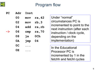
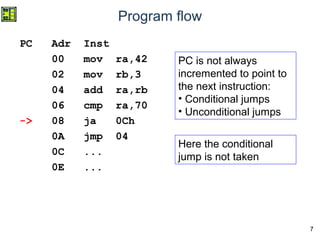
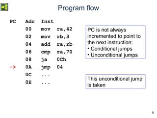

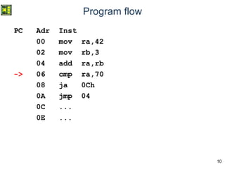
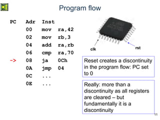
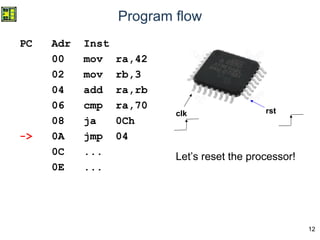
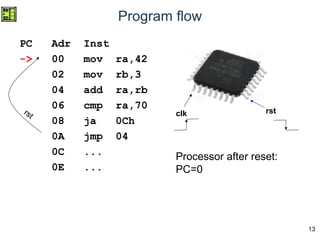
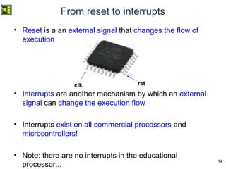
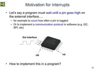
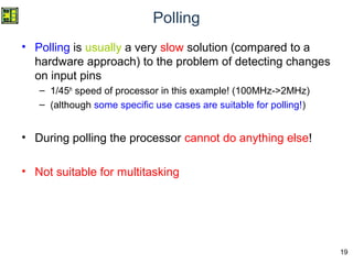
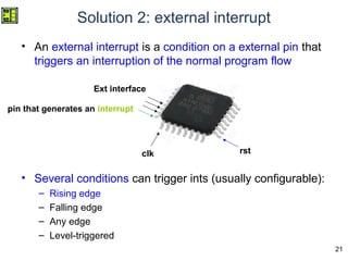
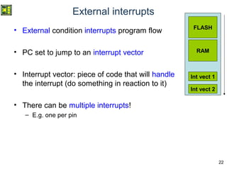
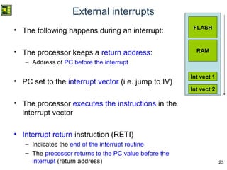
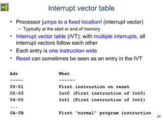
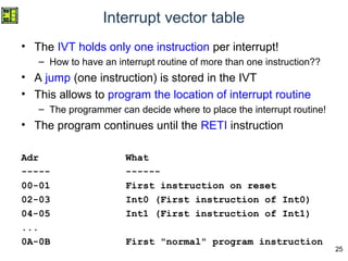
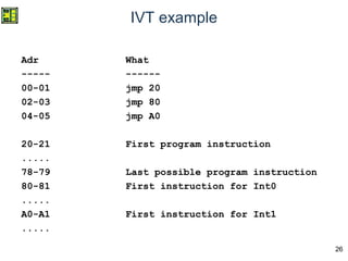
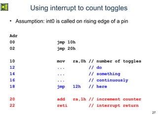
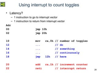

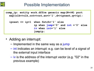


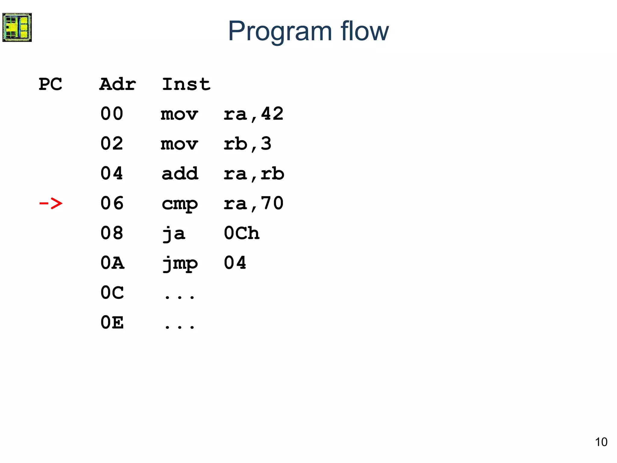
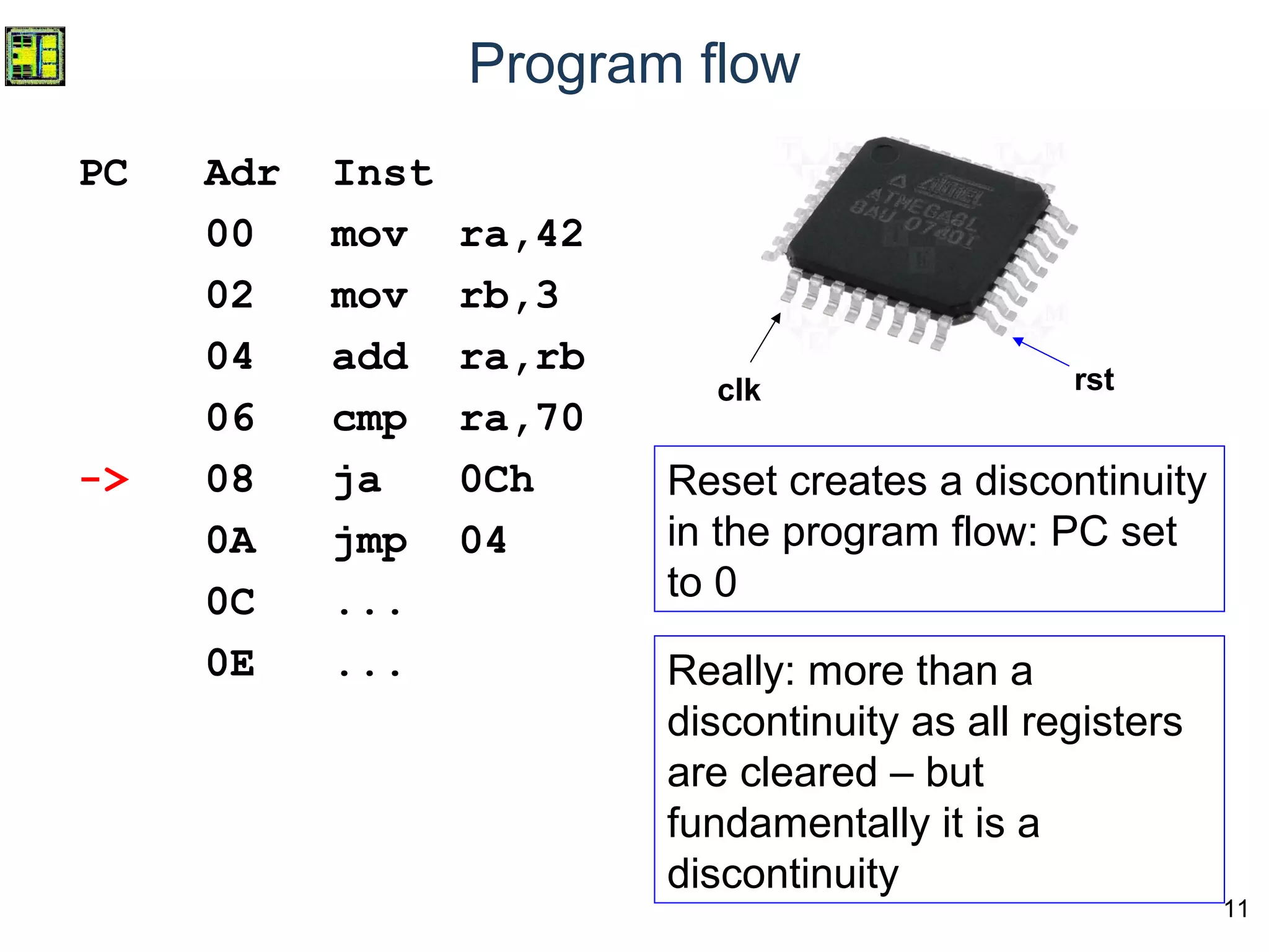
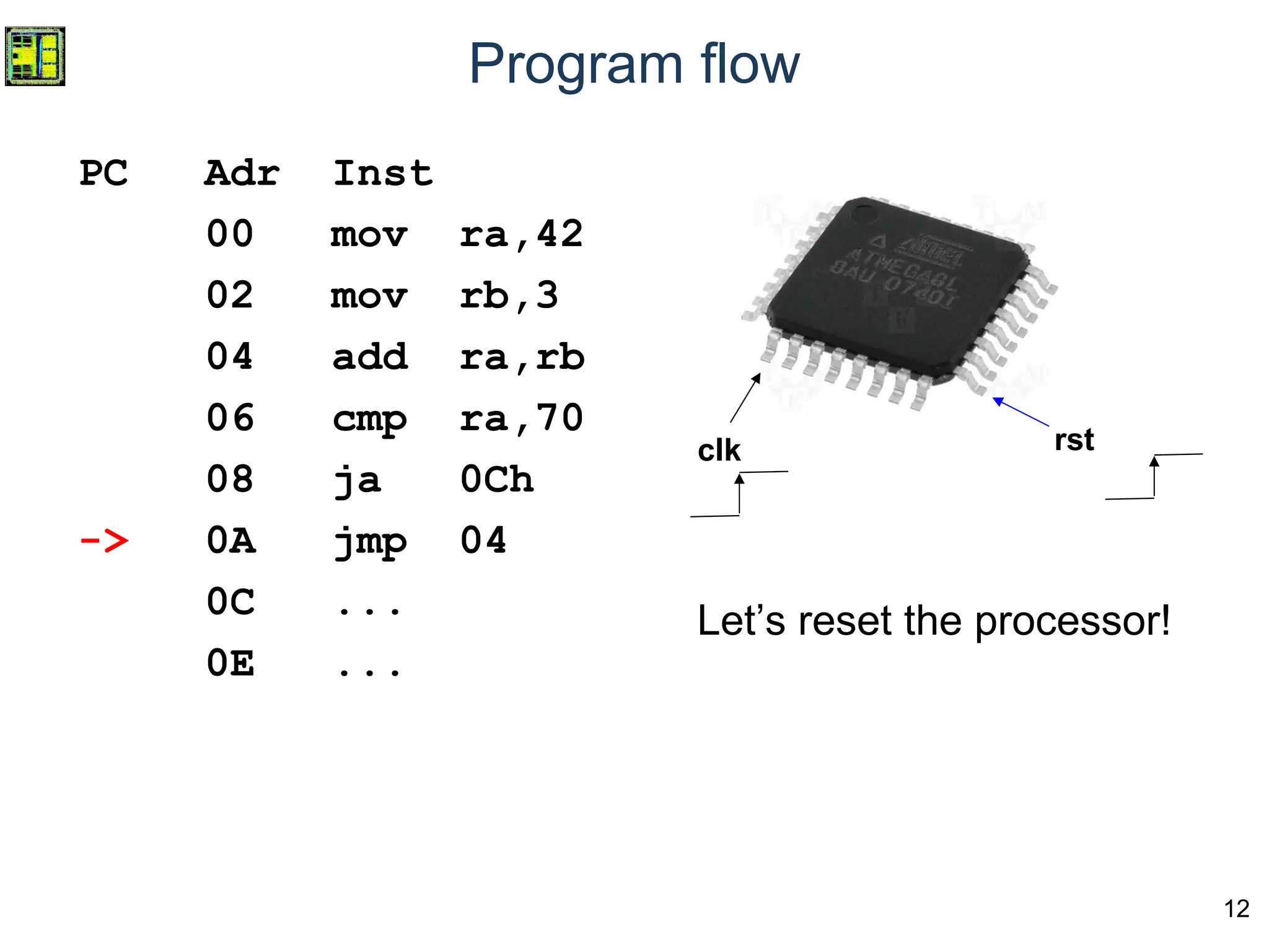

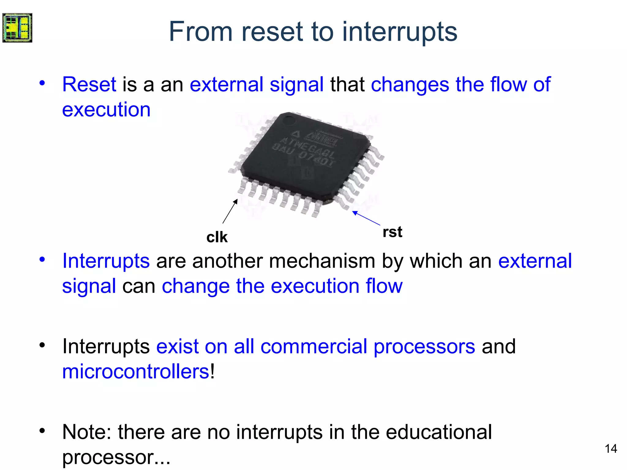
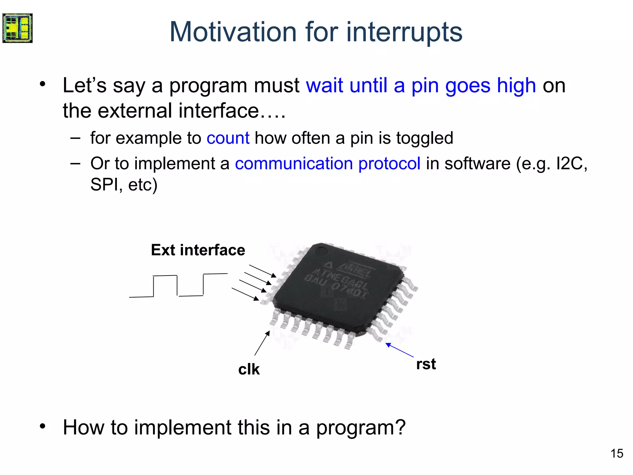
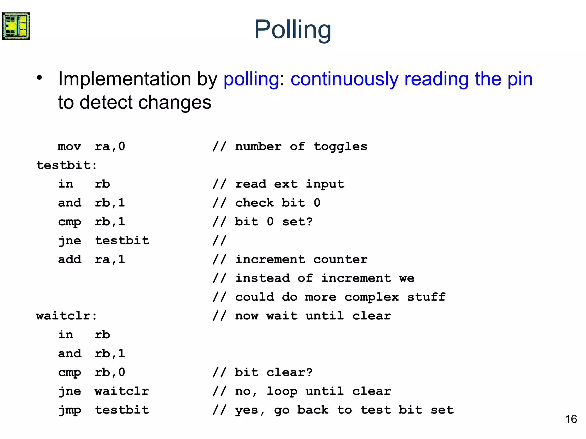
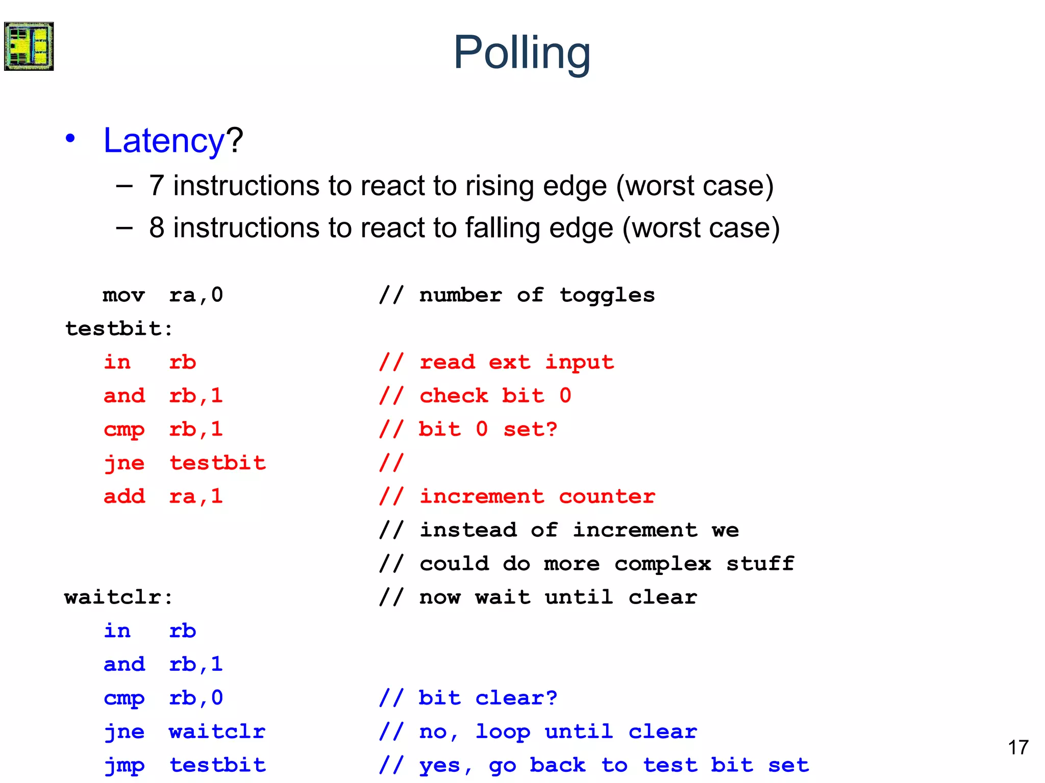
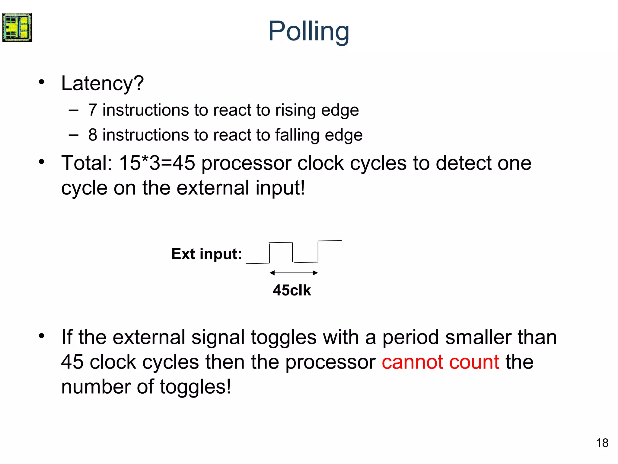

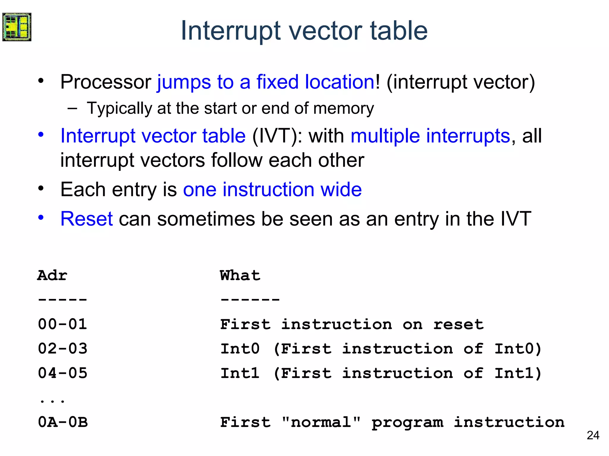
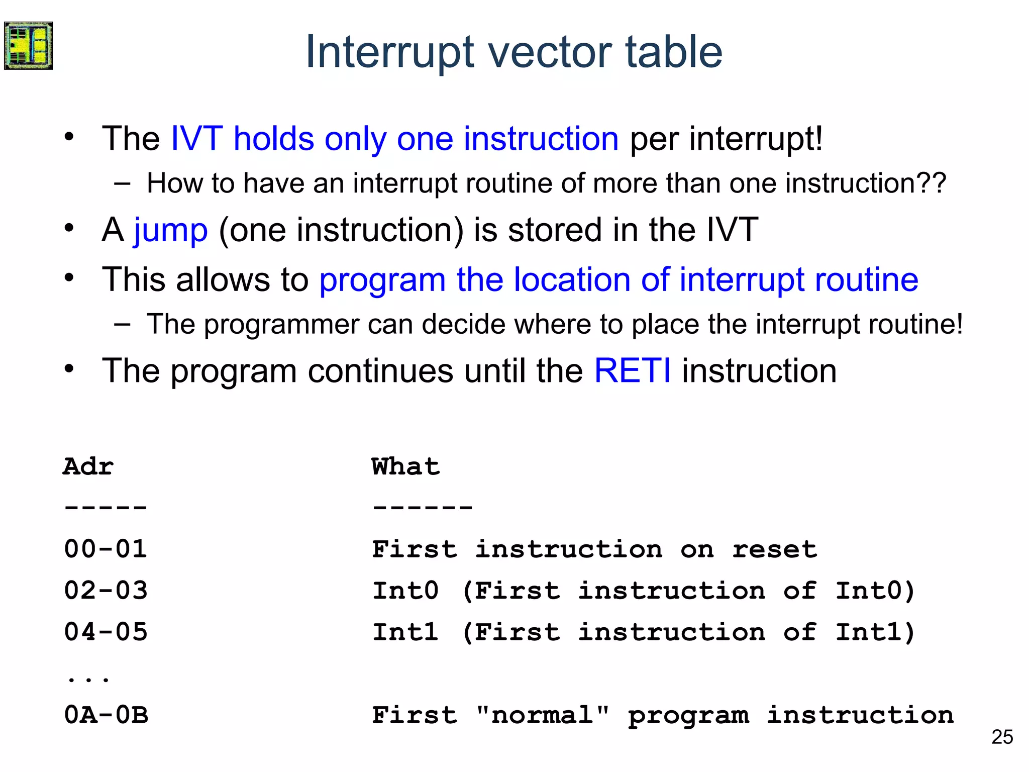
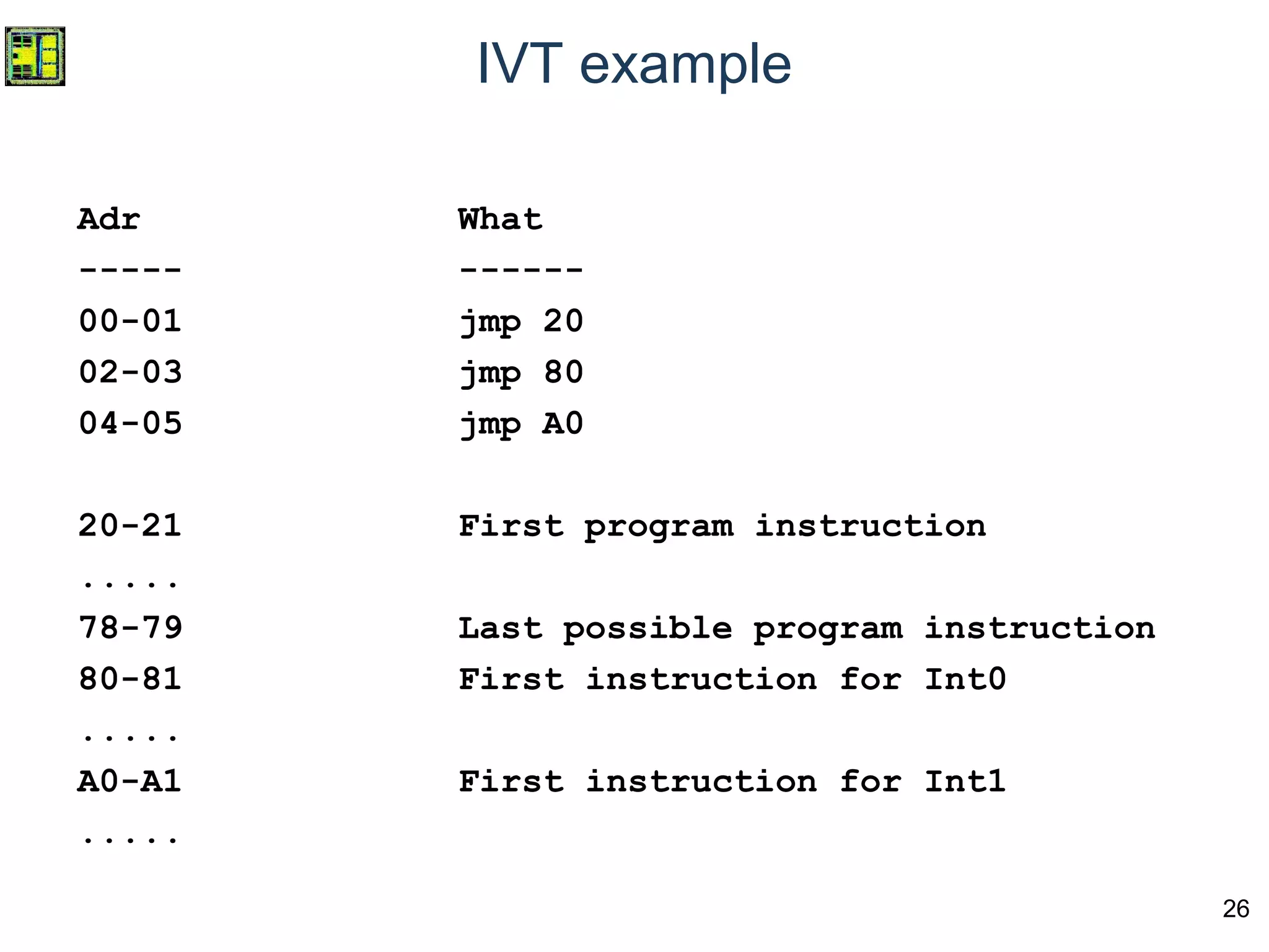
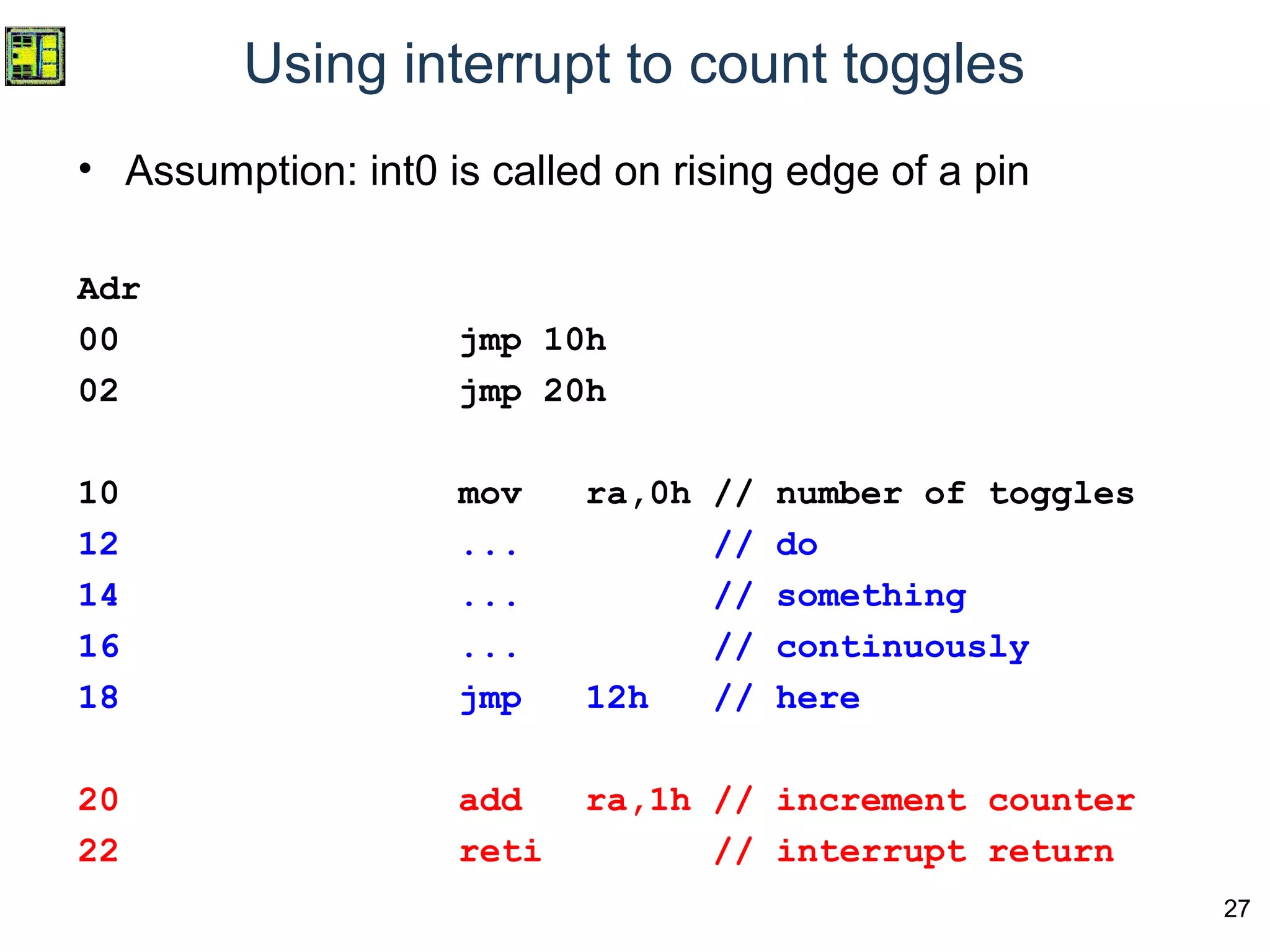
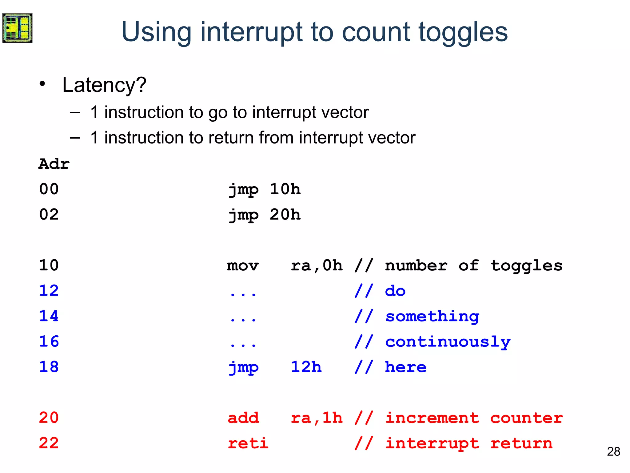


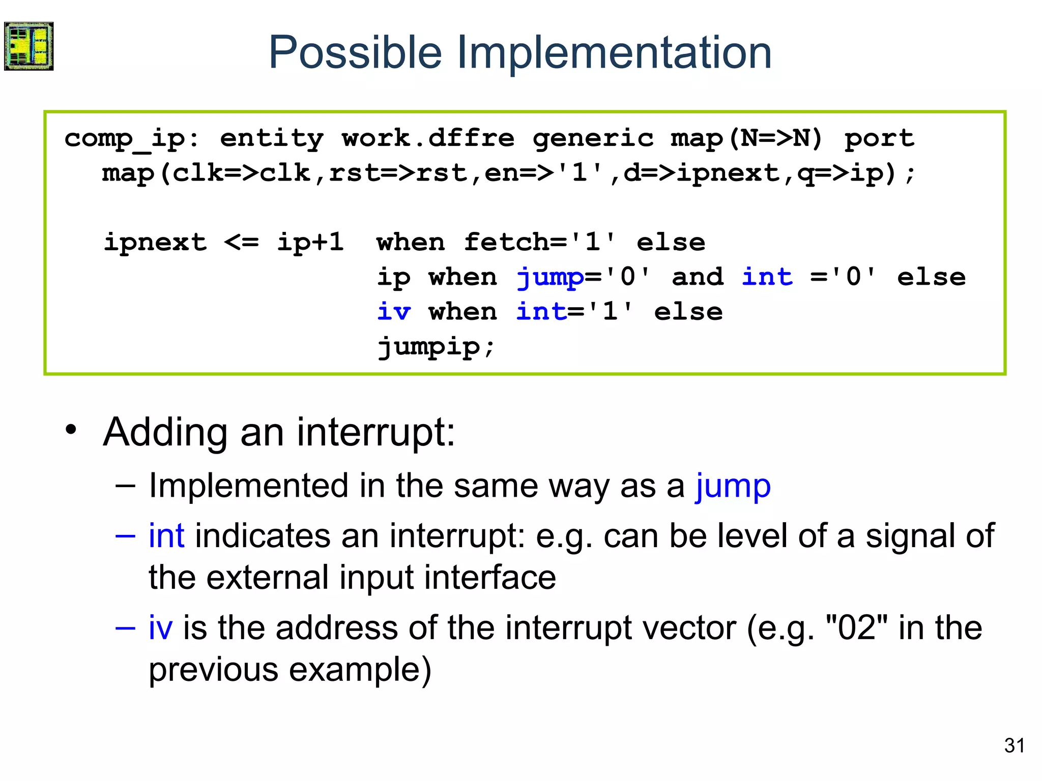
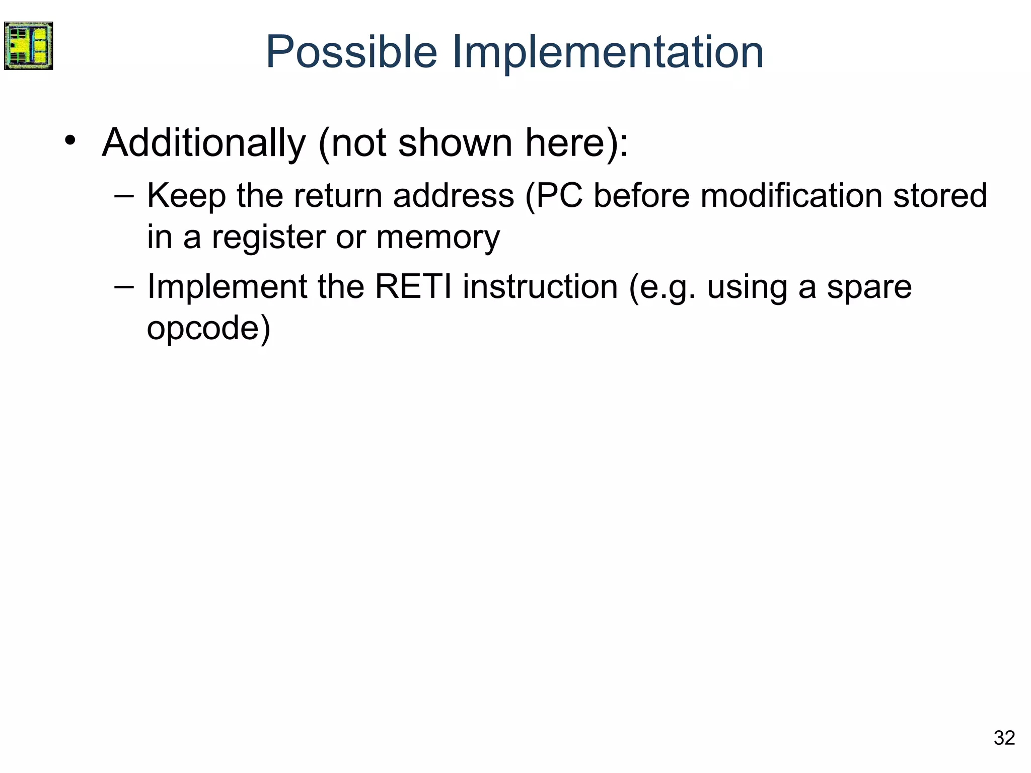
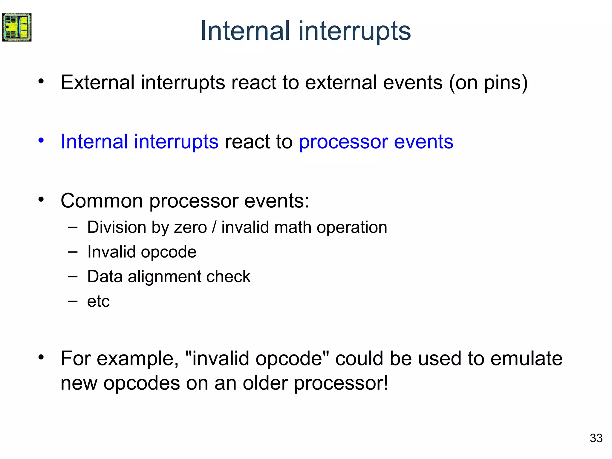

The document discusses digital systems and microprocessor design, focusing on interrupts as a means to change program flow upon hardware events. It explains the concepts of polling versus external interrupts for managing input pins and emphasizes the speed advantage of interrupts in multitasking environments. Additionally, it includes details about handling interrupts, the interrupt vector table, and the distinction between external and internal interrupts.


![[DCG 25] Александр Большев - Never Trust Your Inputs or How To Fool an ADC](https://cdn.slidesharecdn.com/ss_thumbnails/presentationdefconrussia-160406215741-thumbnail.jpg?width=600ounds&width=560&fit=bounds)


