Download to read offline

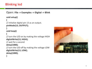
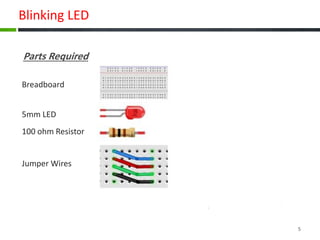
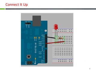
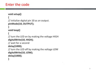

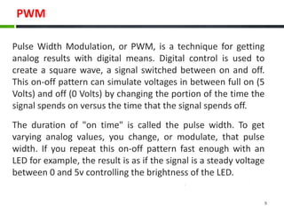

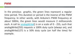


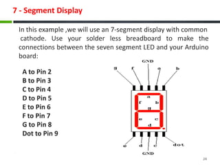

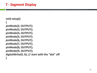


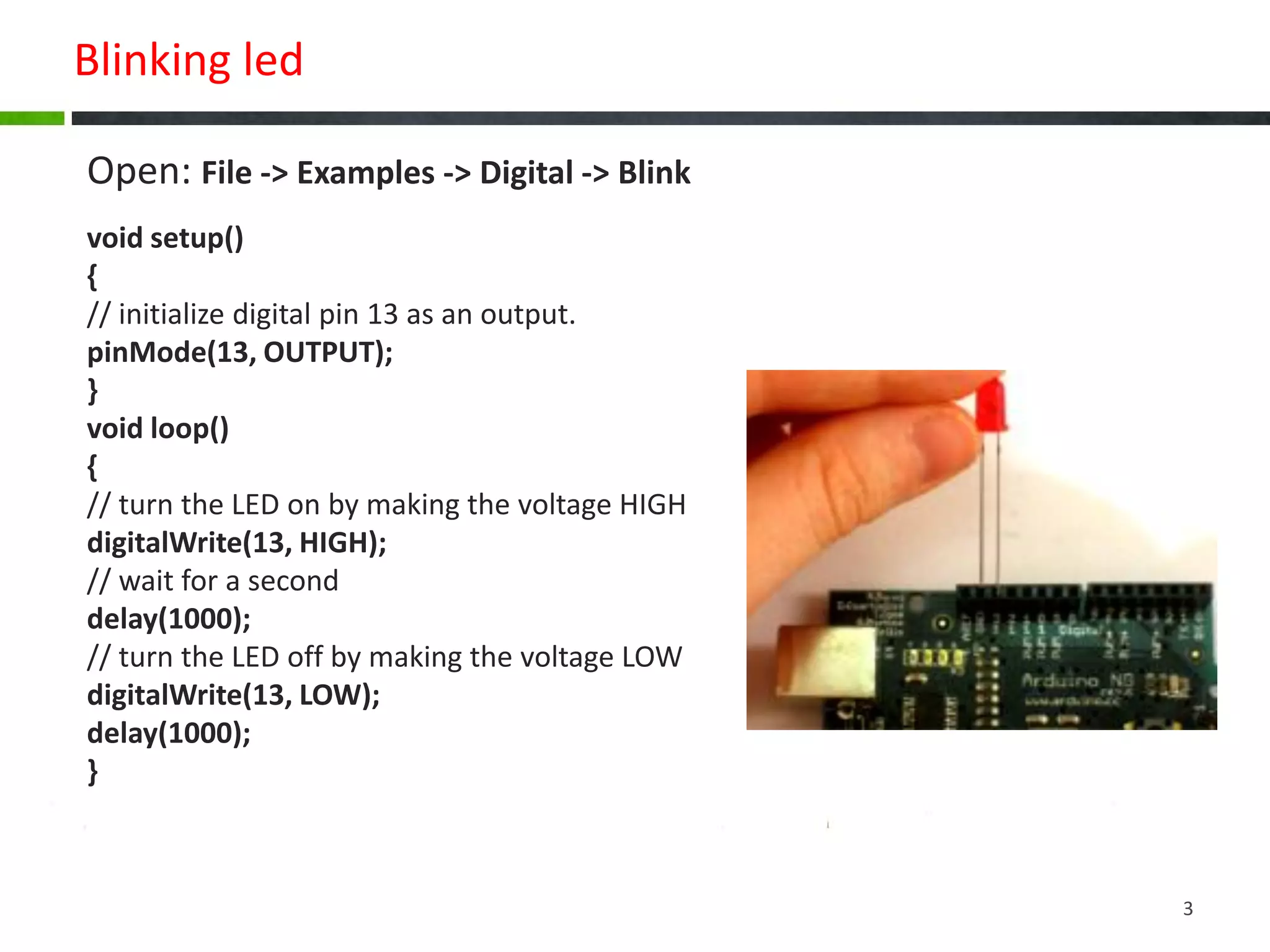

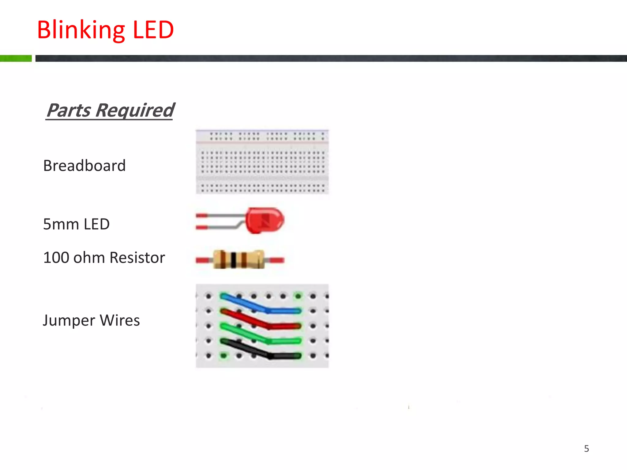
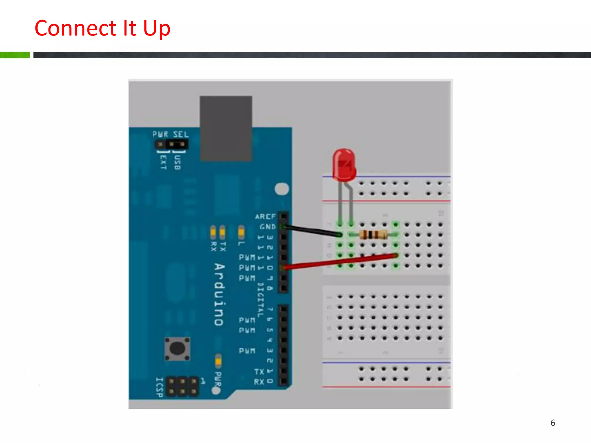
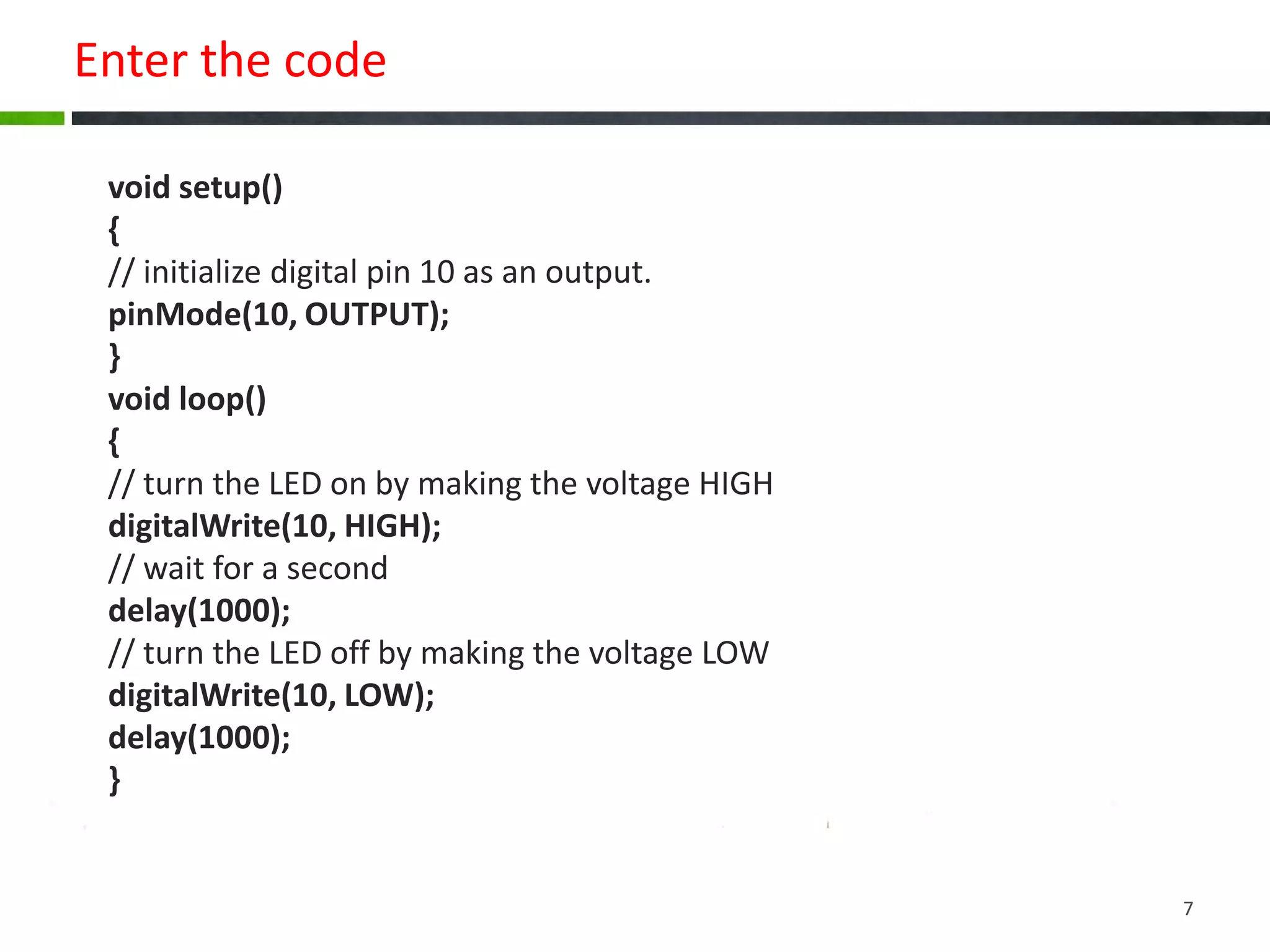

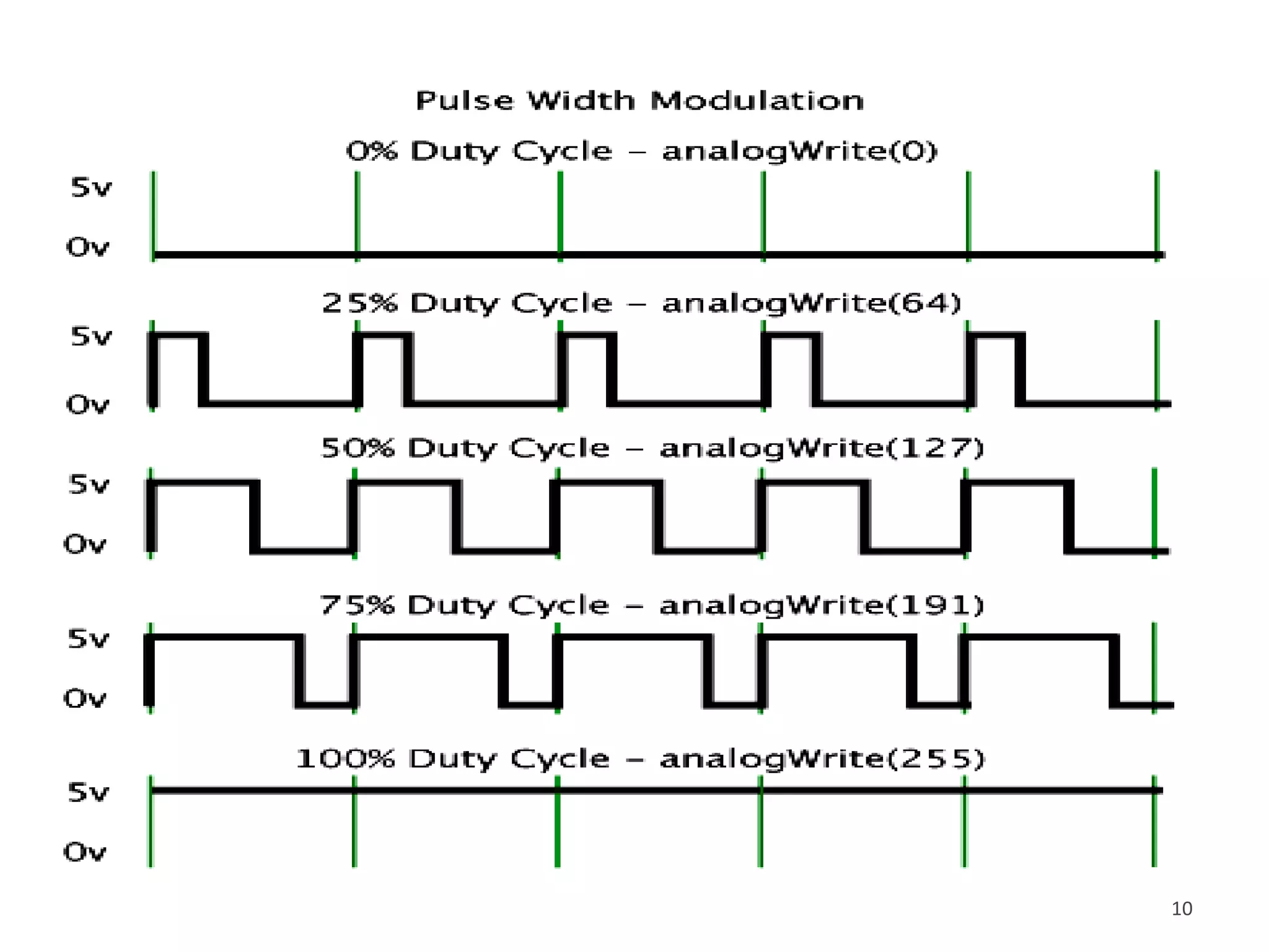


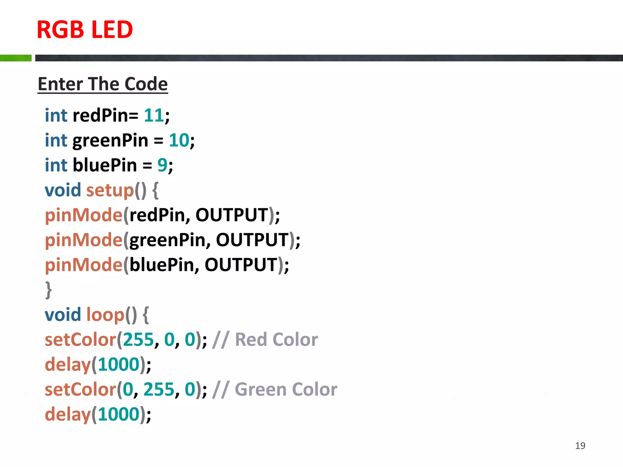
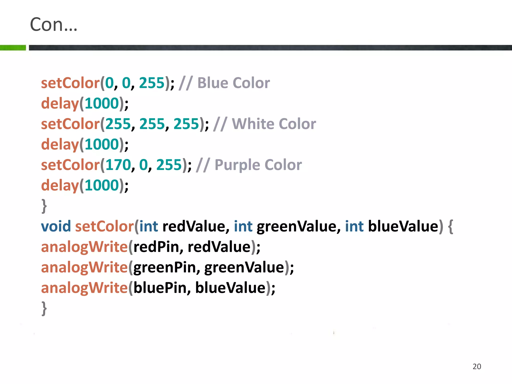

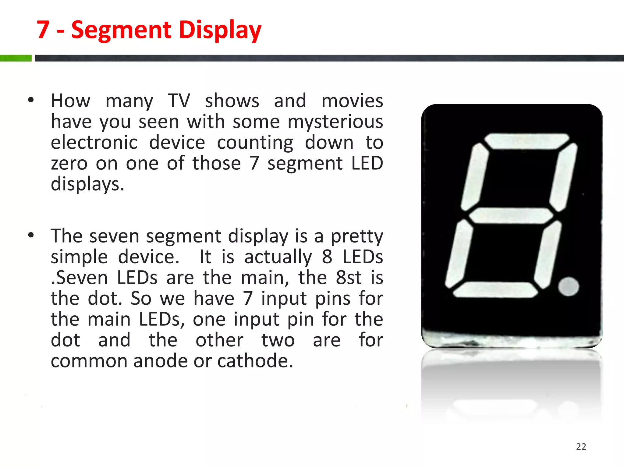
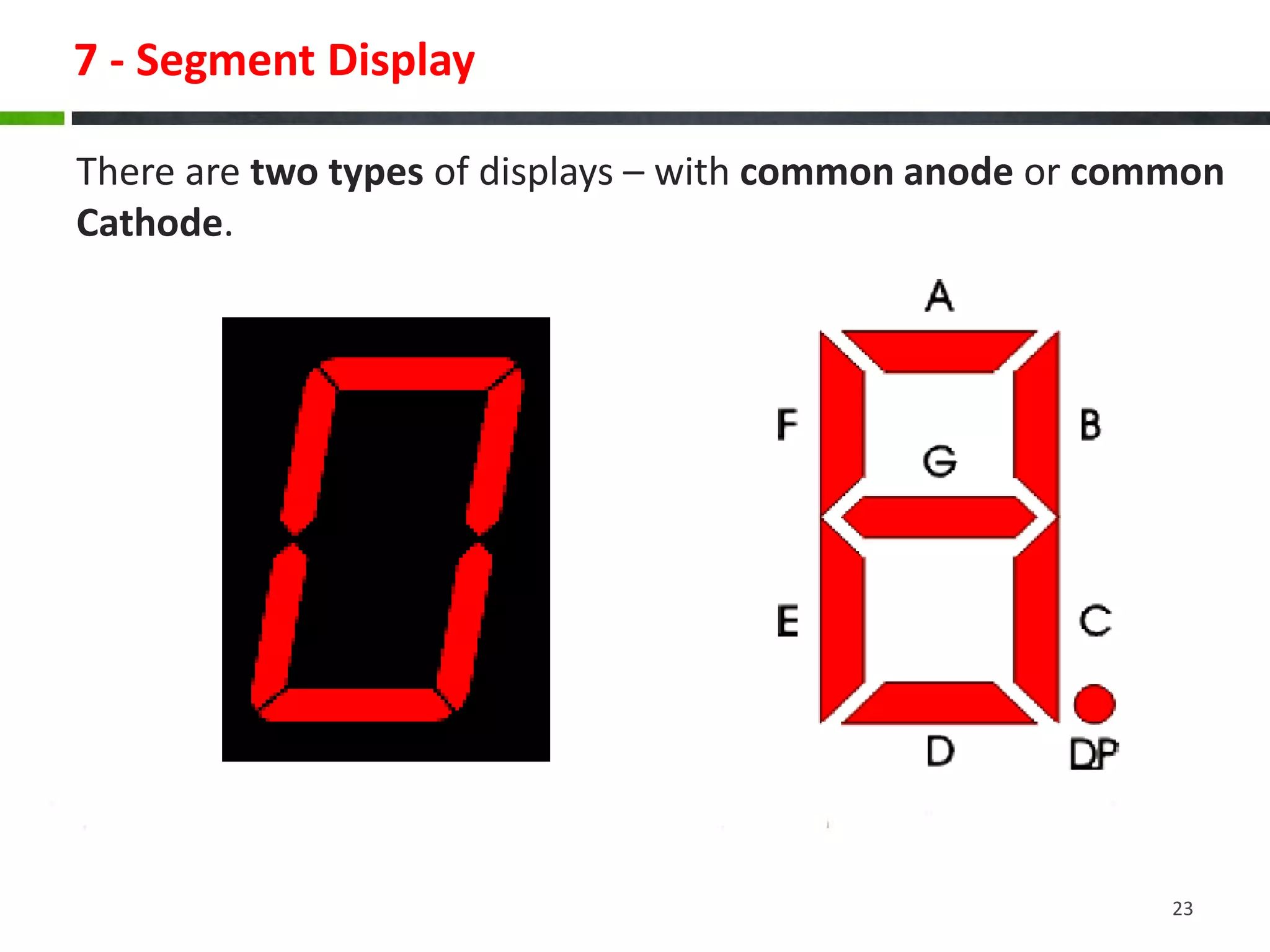
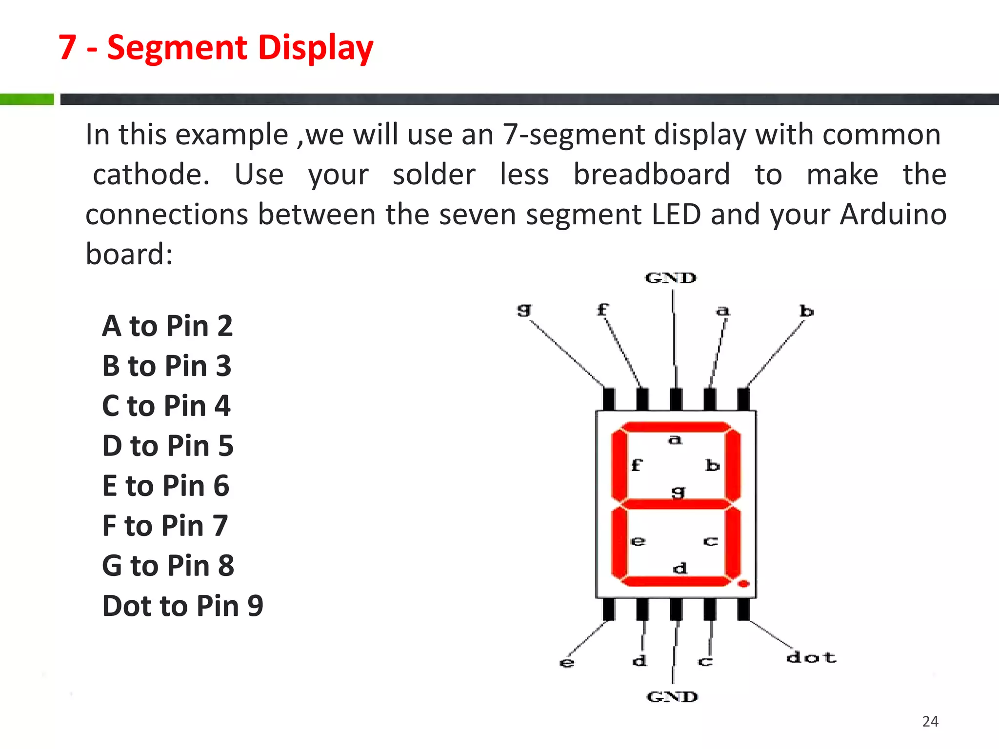
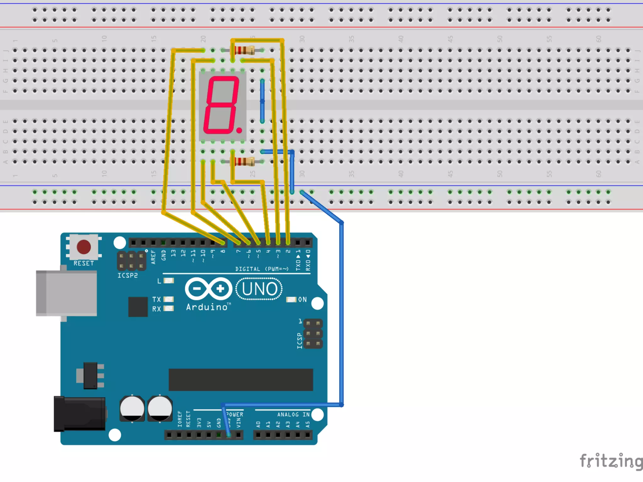
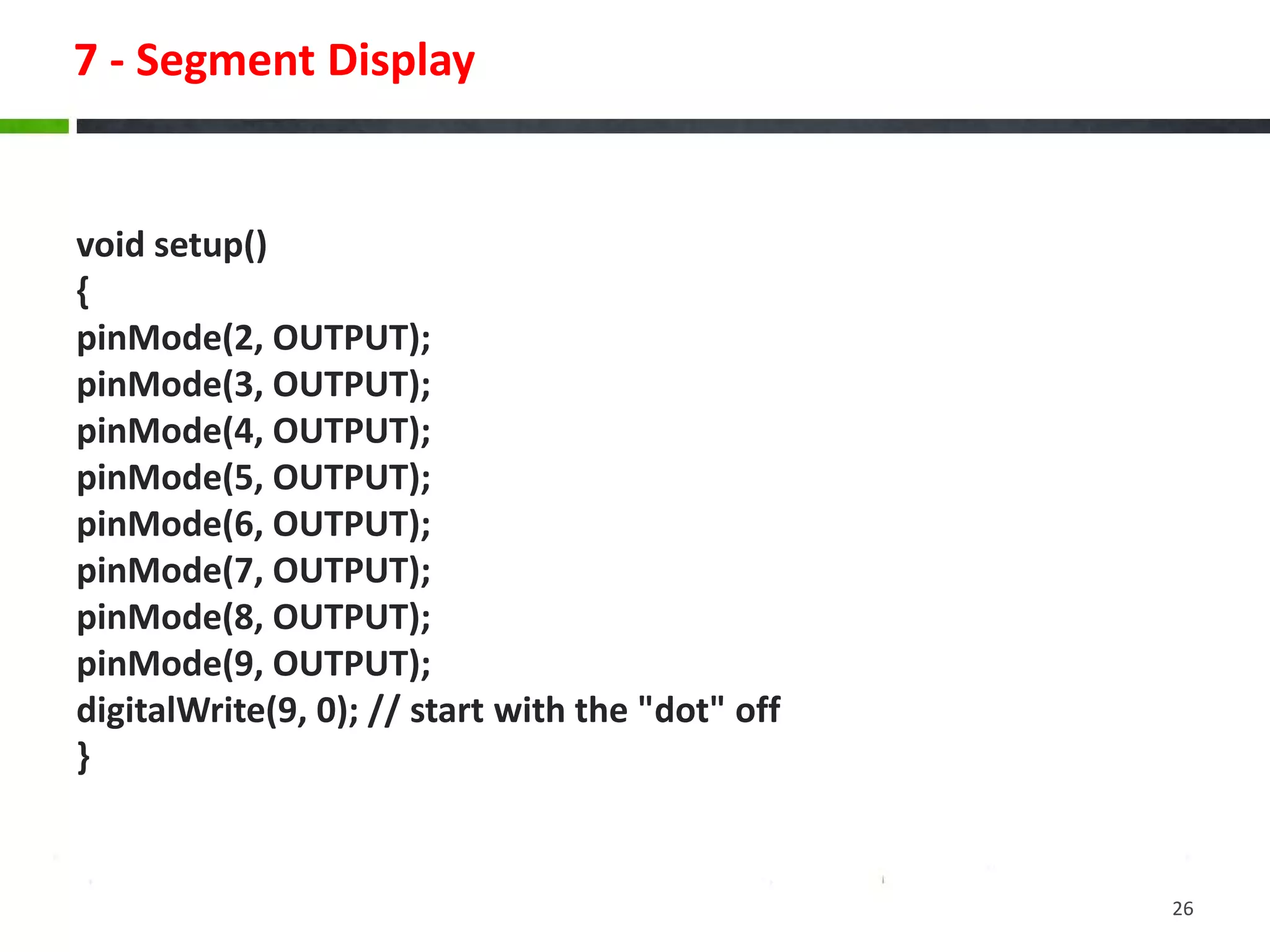
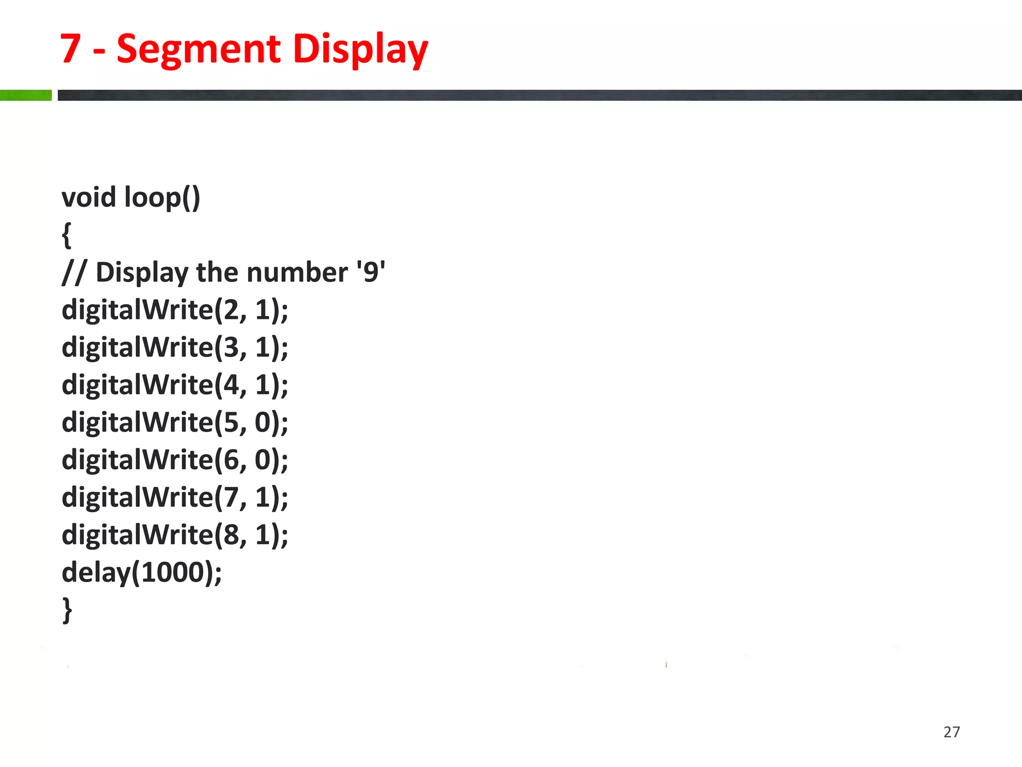


This document provides instructions for building various Arduino-based applications using LEDs, including blinking an LED, using pulse-width modulation to control LED brightness, and displaying numbers on a 7-segment display. It explains how to blink an LED by connecting it to a pin and toggling the pin high and low. It then discusses using pulse-width modulation to simulate analog voltages for fading an LED. Finally, it describes how to interface with a 7-segment display by connecting each segment to a pin and controlling the pins to display numbers.


