Download as PDF, PPTX


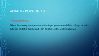

![PULSE WIDTH MODULATION (PWM)
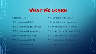
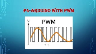
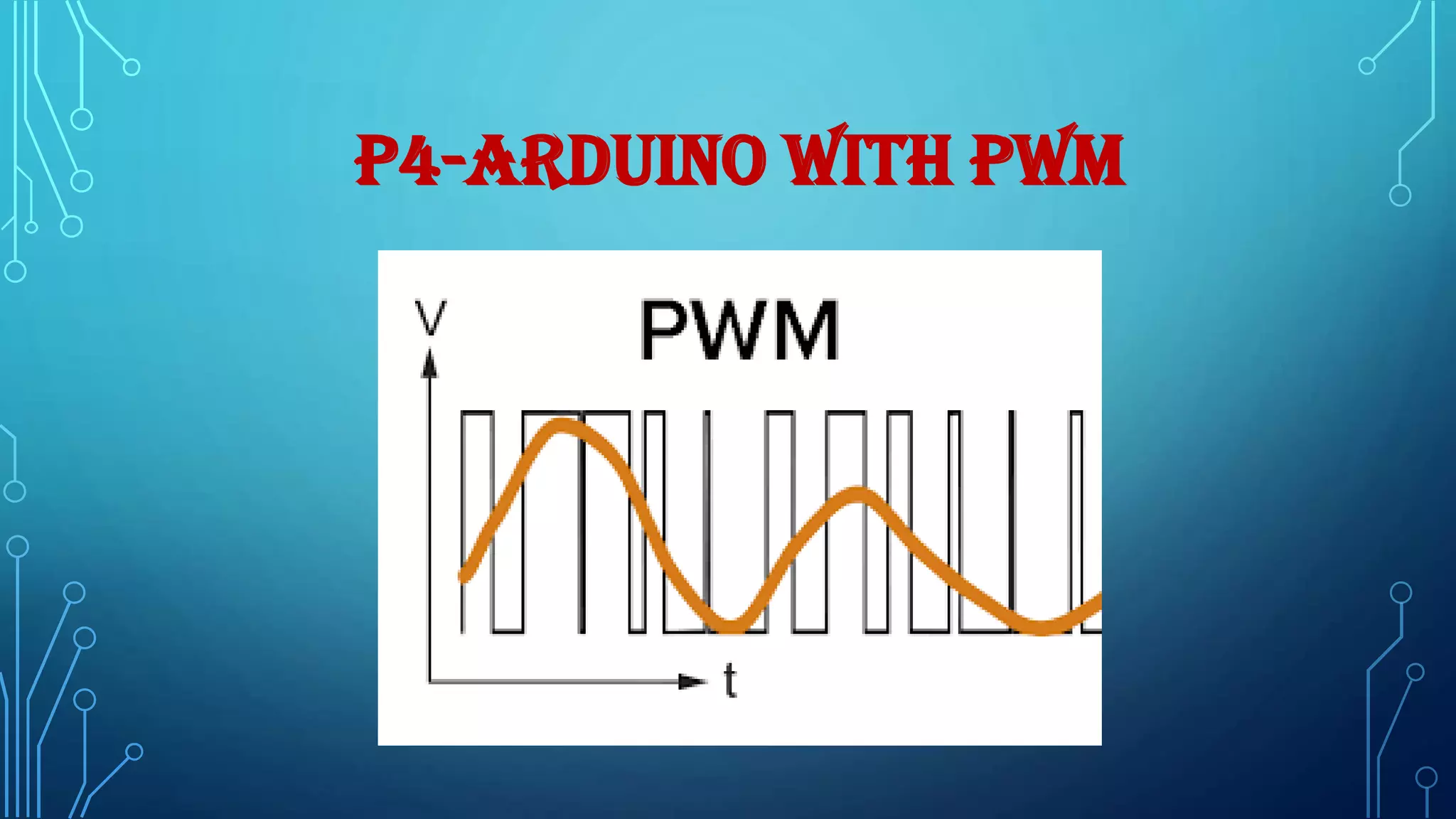
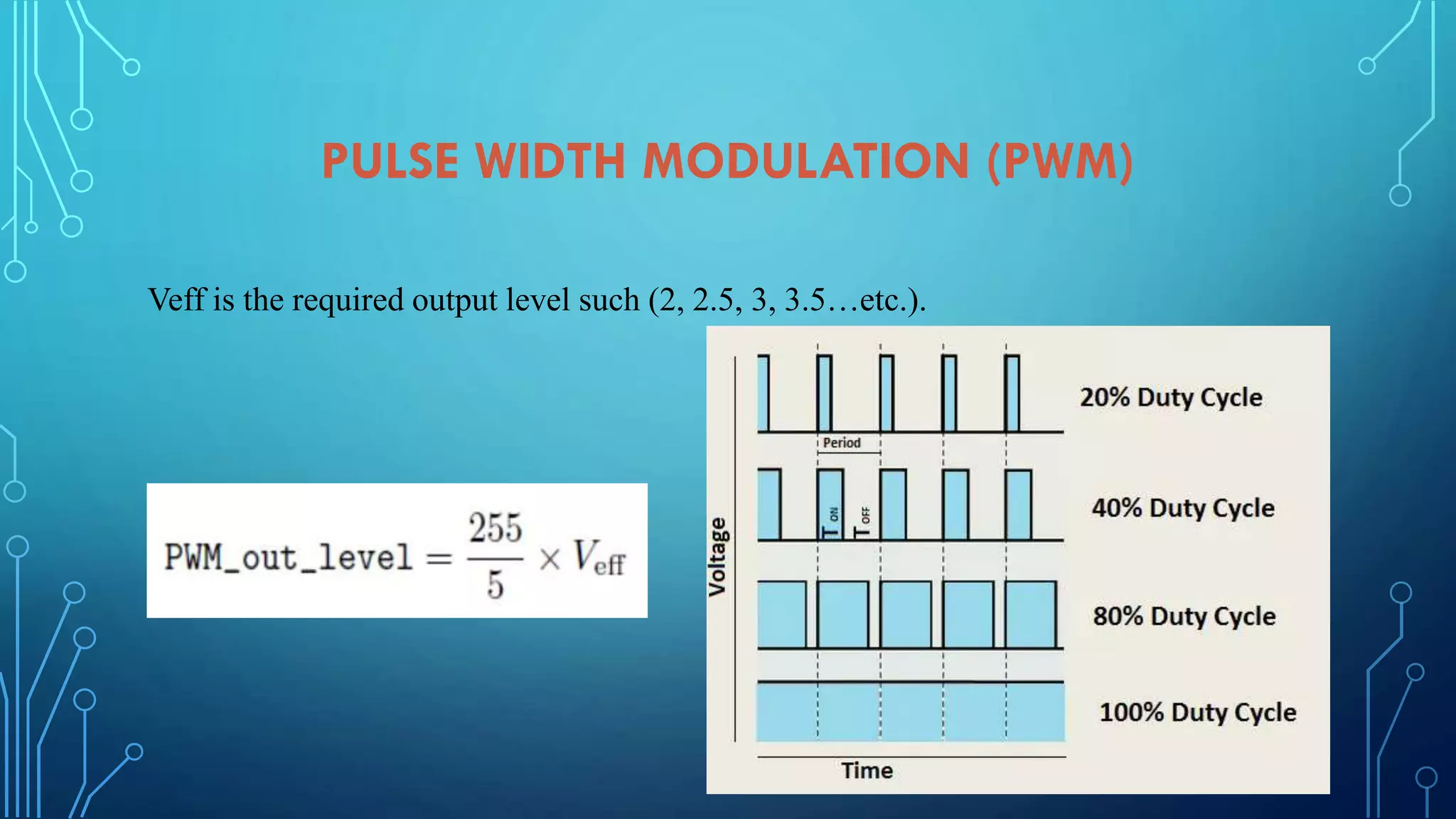
Pulse Width Modulation or PWM is a technique for supplying electrical power to a
load that has a relatively slow response. The supply signal consists of a train of
voltages pulses such that the width of individual pulses controls the elective voltage
level to the load. Both AC and DC signals can be simulated with PWM. In these notes
we will describe the use of PWM on an Arduino for controlling LEDs and DC motors.
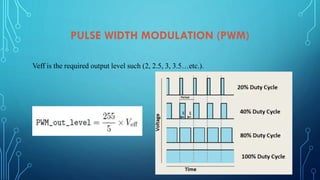
An Arduino Uno has 14 digital I/O pin(s) 6 provide PWM output. The PWM give an
analog output signal in rage[0,255] where each 255samples means 5V digital so, to
determine the required analog output voltage use the relation:](https://image.slidesharecdn.com/embeddedsystemcourseprojectsslideshare-210211164916/85/Embedded-system-course-projects-Arduino-Course-36-320.jpg)


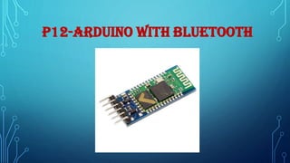
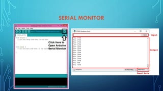
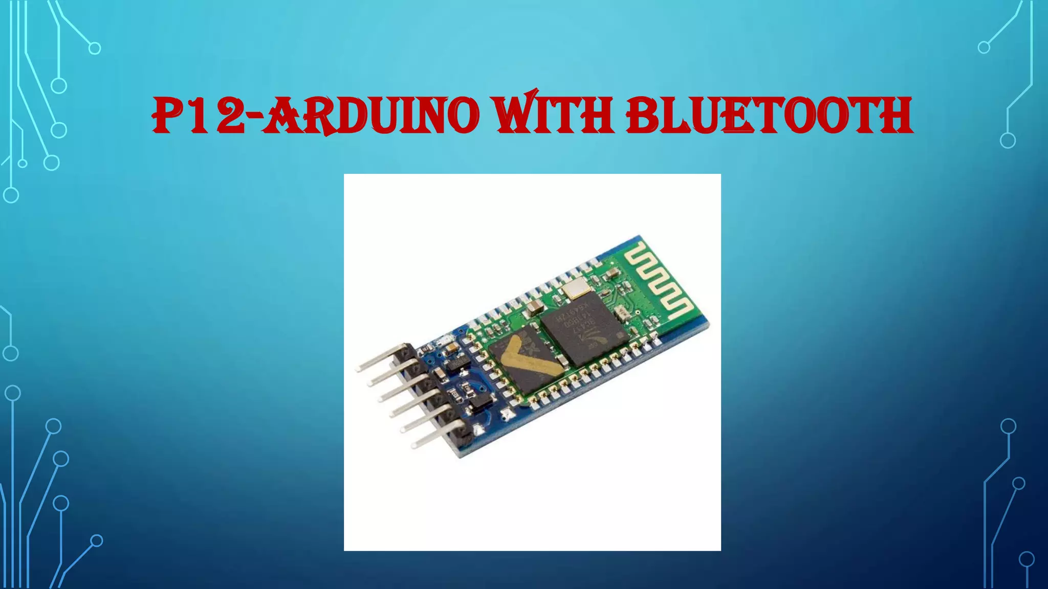
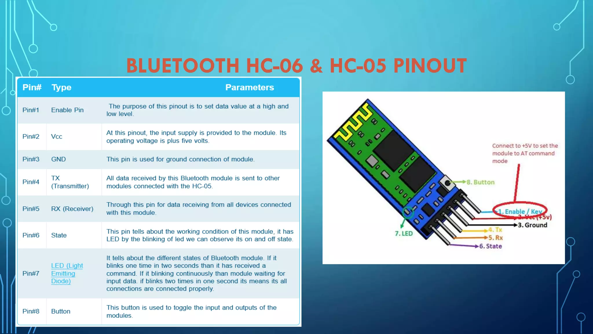
![P12-ARDUINO WITH BLUETOOTH
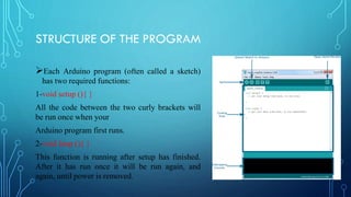
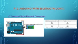
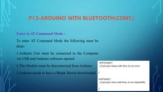
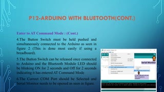
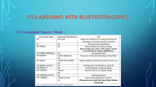
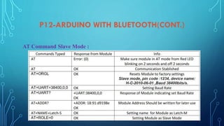
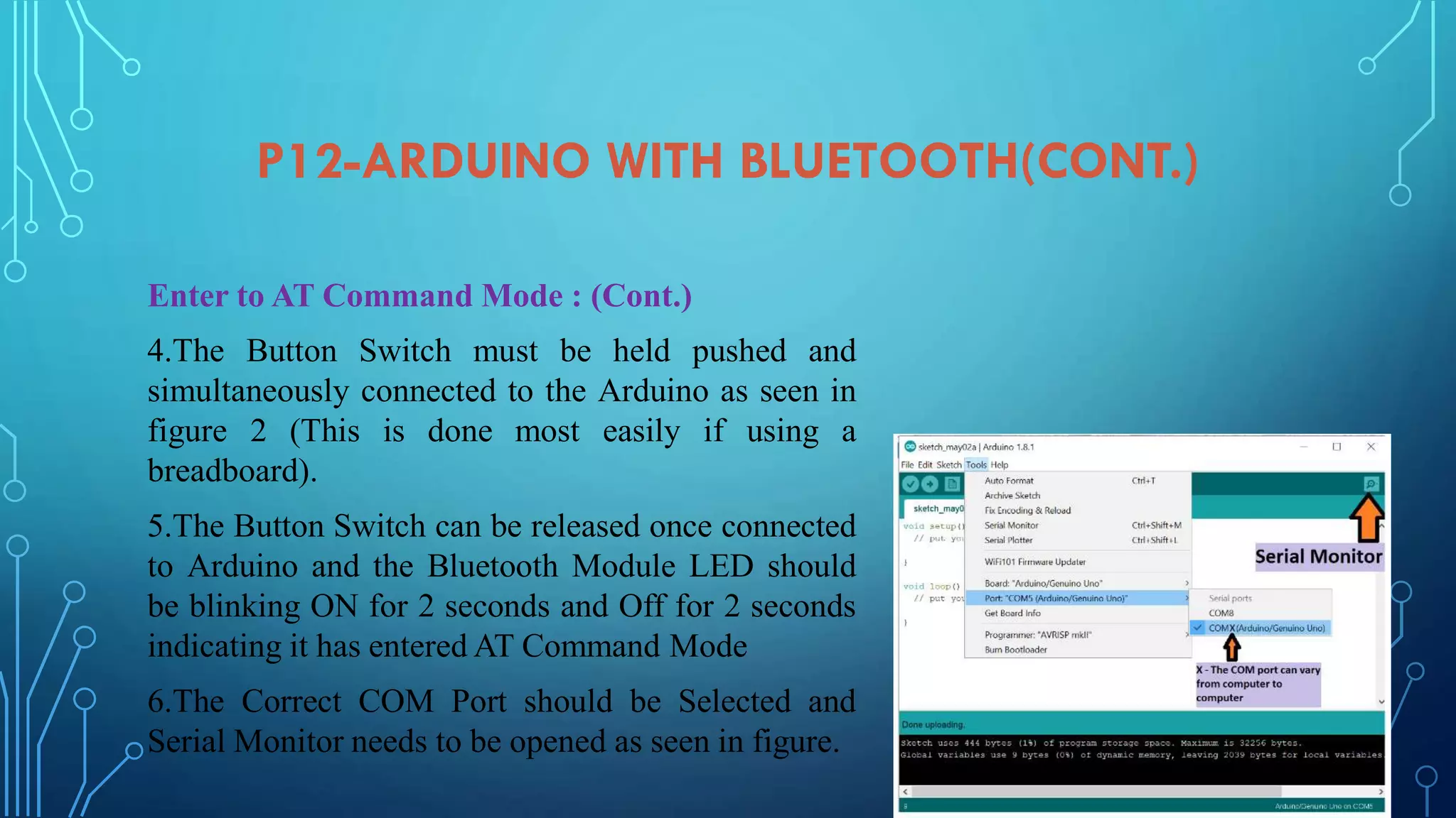
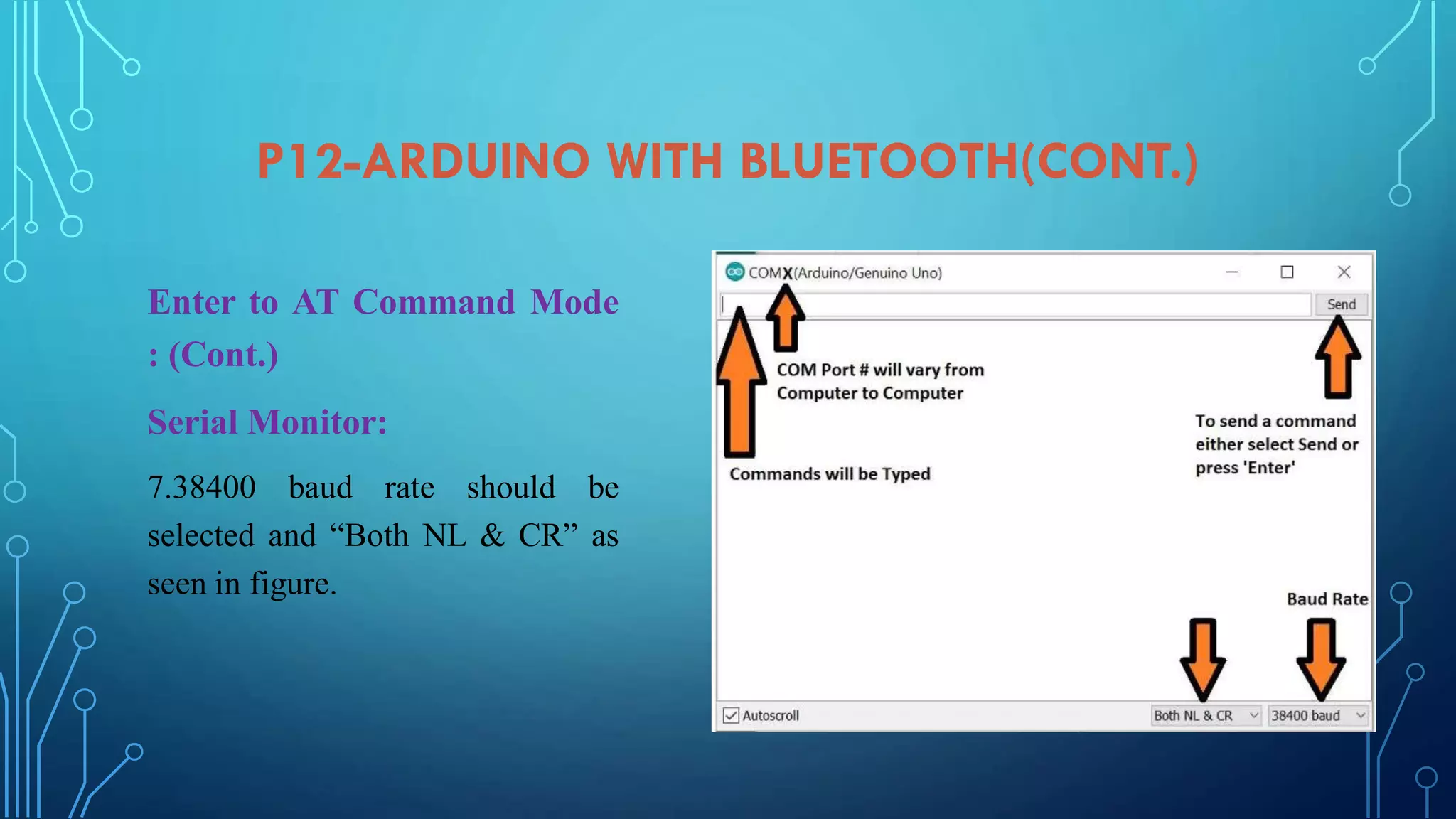
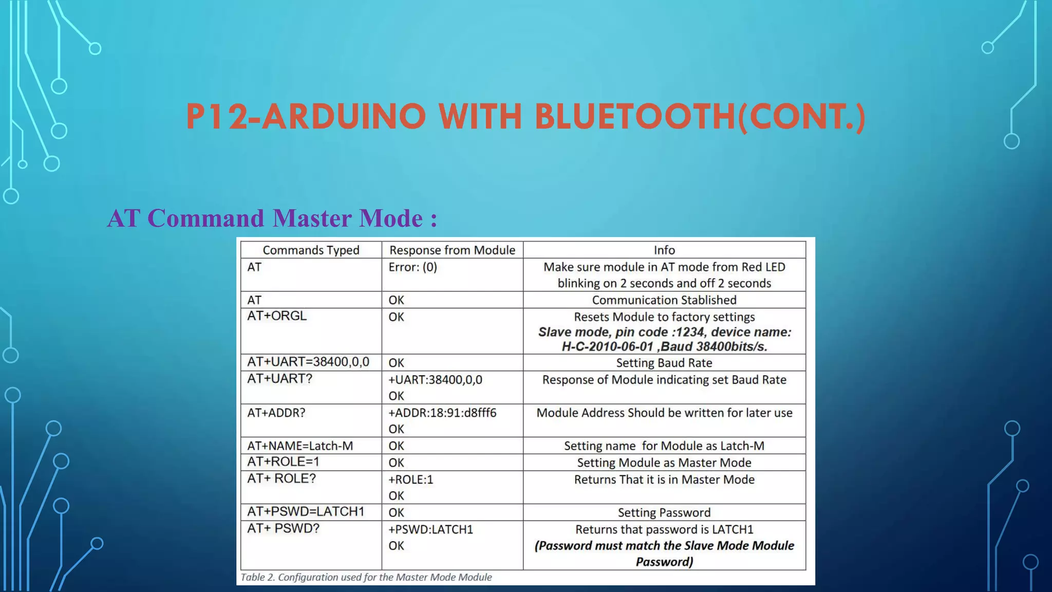
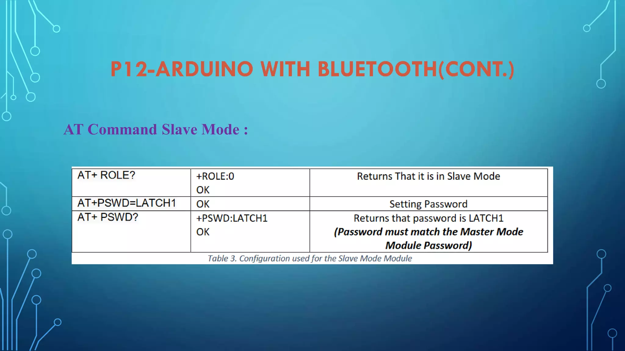
AT Command Mode:
AT mode refers to the form of communication to the HC-05 Bluetooth Module.
AT Commands are short for ATtention Commandswhich is a command
languageused for modems known as theHayes command set. Hayes command
setis a specific command language originally developed by Dennis Hayes for
the Hayes Smartmodem 300 baud modem in 1981 [2].The HC-05 Bluetooth
Module was used due to its ability to be configuredas Master or Slave mode as
well as adding a password to the module.](https://image.slidesharecdn.com/embeddedsystemcourseprojectsslideshare-210211164916/85/Embedded-system-course-projects-Arduino-Course-94-320.jpg)


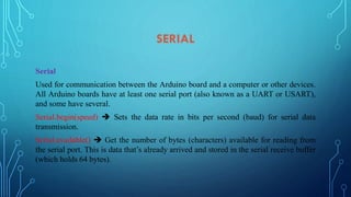
![PULSE WIDTH MODULATION (PWM)
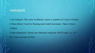
Pulse Width Modulation or PWM is a technique for supplying electrical power to a
load that has a relatively slow response. The supply signal consists of a train of
voltages pulses such that the width of individual pulses controls the elective voltage
level to the load. Both AC and DC signals can be simulated with PWM. In these notes
we will describe the use of PWM on an Arduino for controlling LEDs and DC motors.
An Arduino Uno has 14 digital I/O pin(s) 6 provide PWM output. The PWM give an
analog output signal in rage[0,255] where each 255samples means 5V digital so, to
determine the required analog output voltage use the relation:](https://image.slidesharecdn.com/embeddedsystemcourseprojectsslideshare-210211164916/75/Embedded-system-course-projects-Arduino-Course-36-2048.jpg)


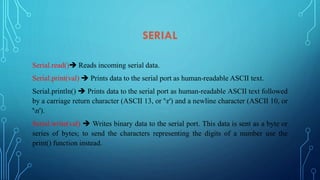
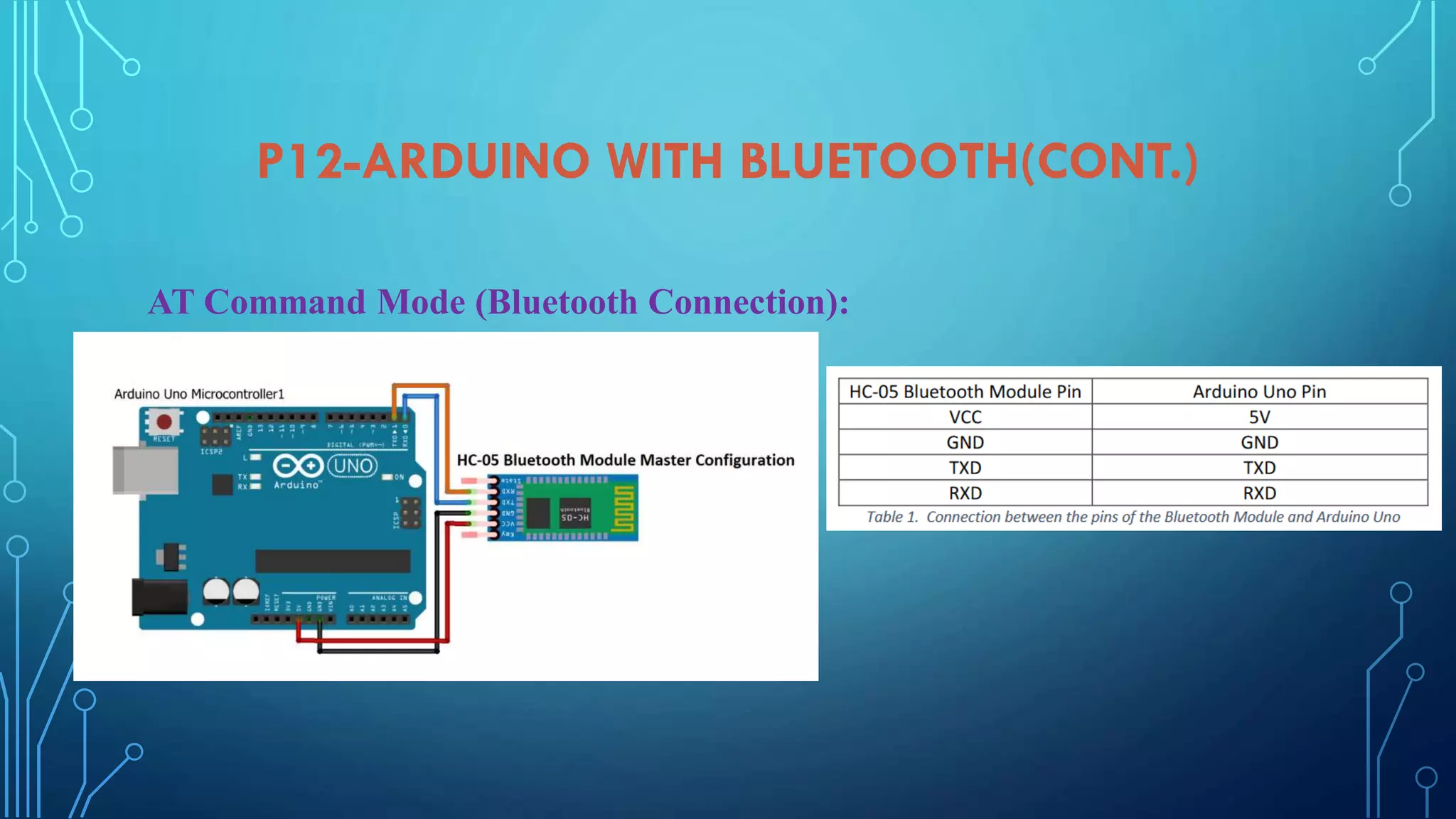
![P12-ARDUINO WITH BLUETOOTH
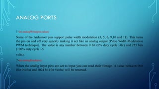
AT Command Mode:
AT mode refers to the form of communication to the HC-05 Bluetooth Module.
AT Commands are short for ATtention Commandswhich is a command
languageused for modems known as theHayes command set. Hayes command
setis a specific command language originally developed by Dennis Hayes for
the Hayes Smartmodem 300 baud modem in 1981 [2].The HC-05 Bluetooth
Module was used due to its ability to be configuredas Master or Slave mode as
well as adding a password to the module.](https://image.slidesharecdn.com/embeddedsystemcourseprojectsslideshare-210211164916/75/Embedded-system-course-projects-Arduino-Course-94-2048.jpg)


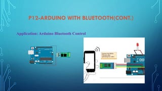
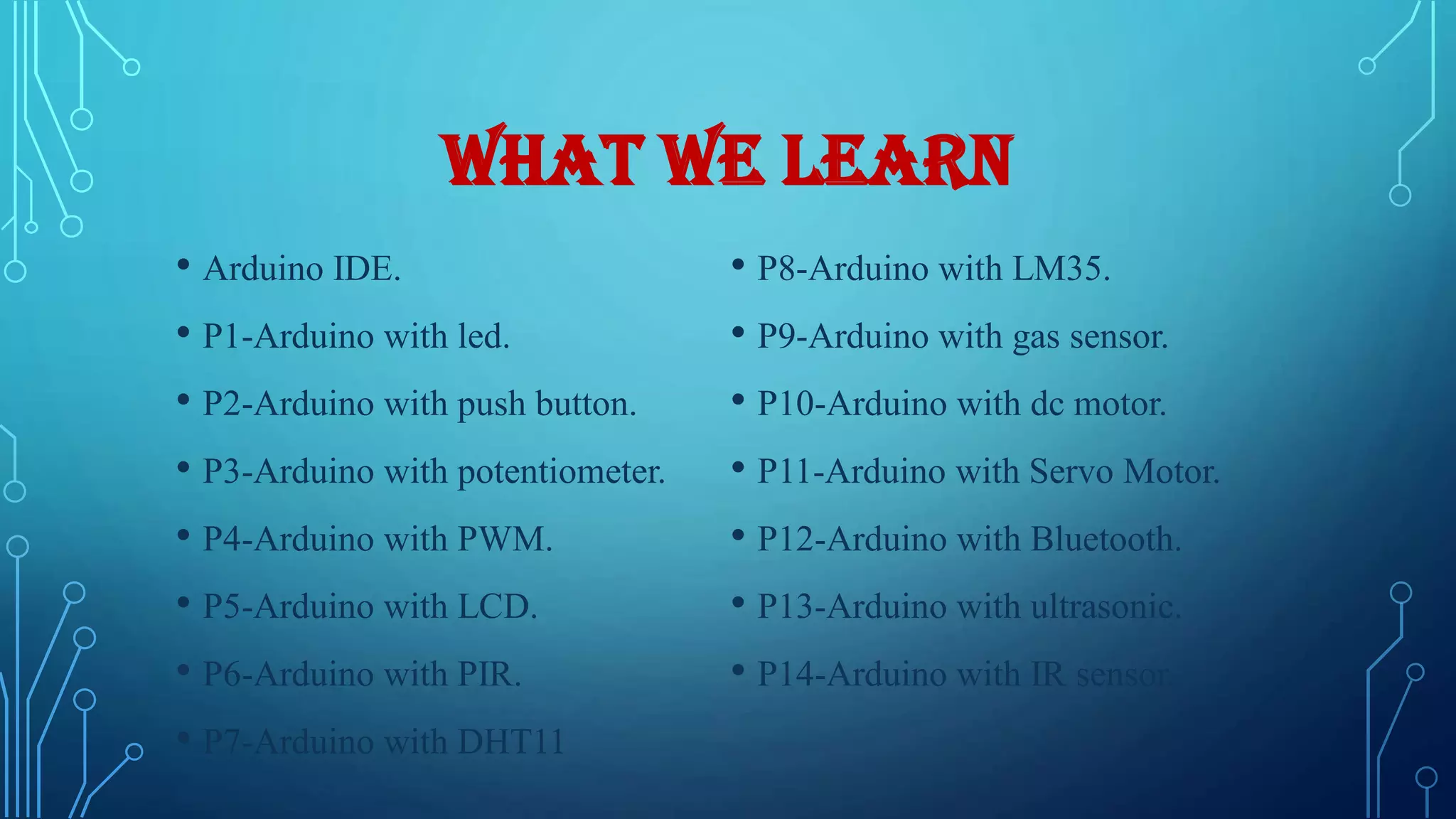
The document outlines an Arduino course that covers various projects involving components like sensors, motors, and displays. Key topics include using the Arduino IDE for programming with sketches, controlling outputs through PWM, and interfacing with various modules like Bluetooth and ultrasonic sensors. It provides detailed instructions and circuit designs for hands-on projects such as using LEDs, push buttons, and LCDs with the Arduino Uno.
Introduction of the Arduino course, learning objectives, and projects covering different Arduino applications.
Discussion on Arduino Integrated Development Environment (IDE) used for programming Arduino boards.
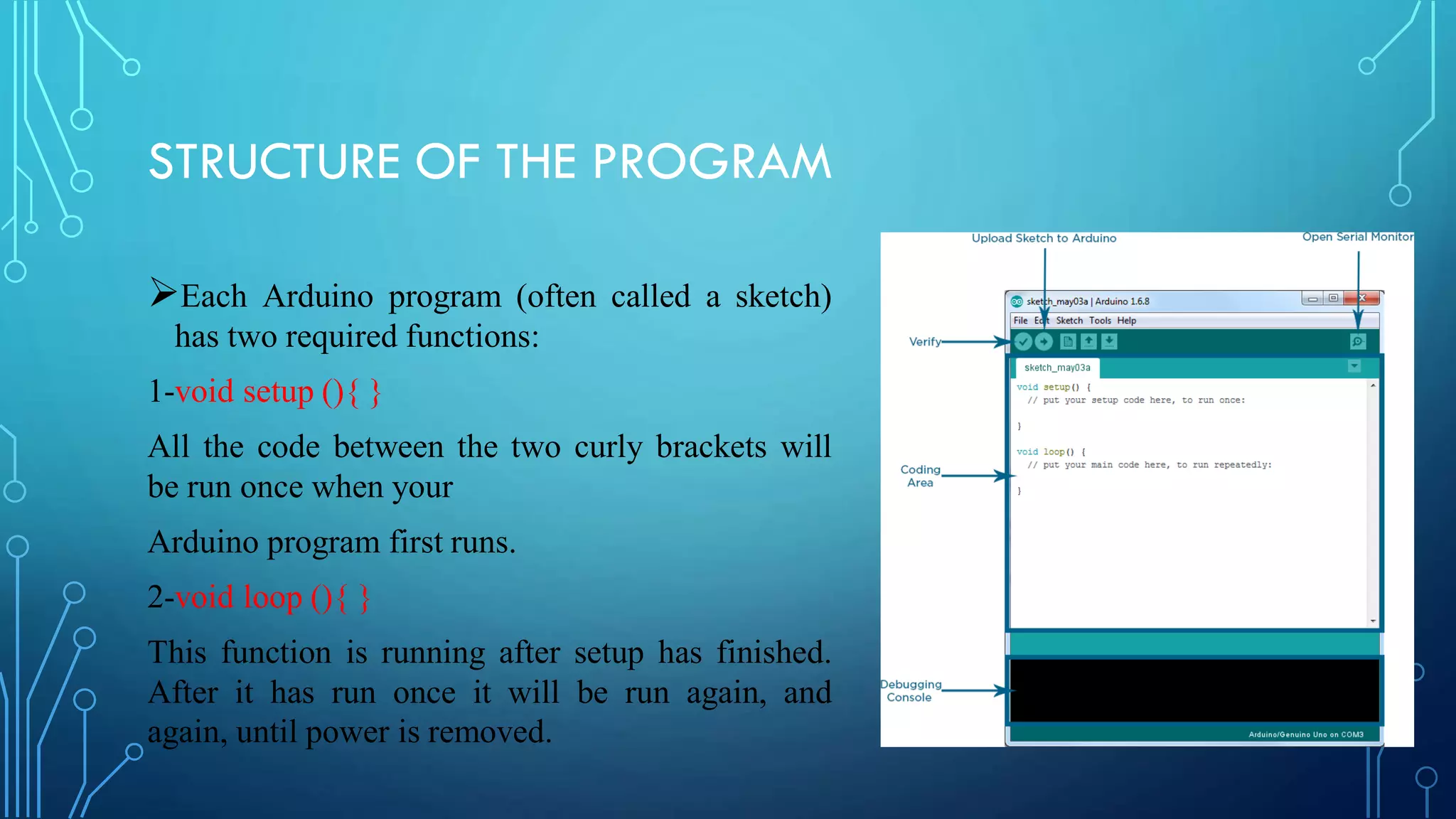
Basics of Arduino programming structure including setup and loop functions, and variable types: int, float, char.
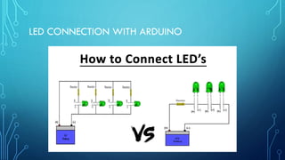
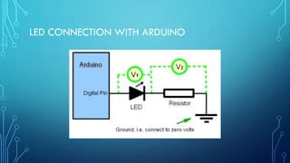
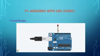
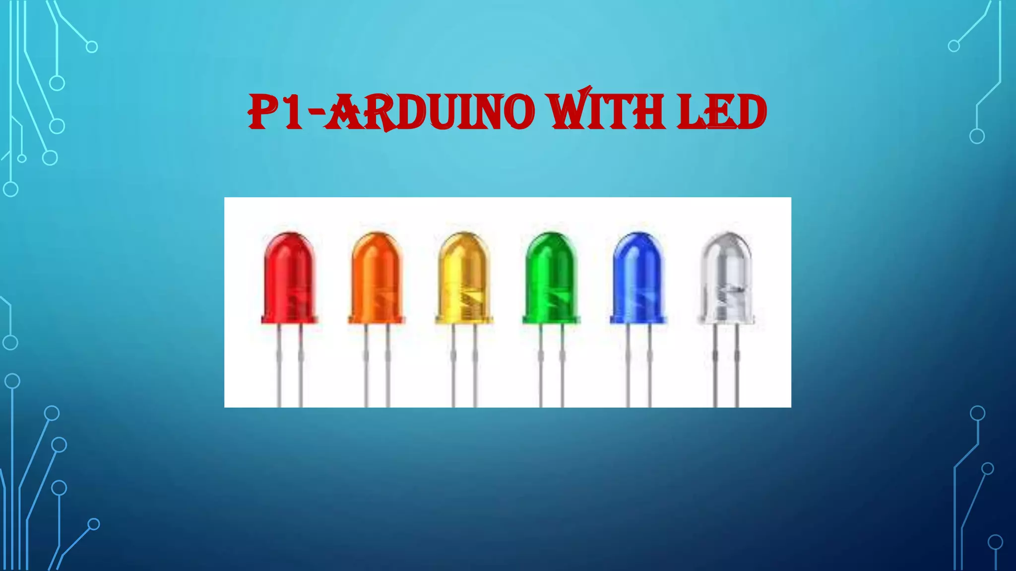
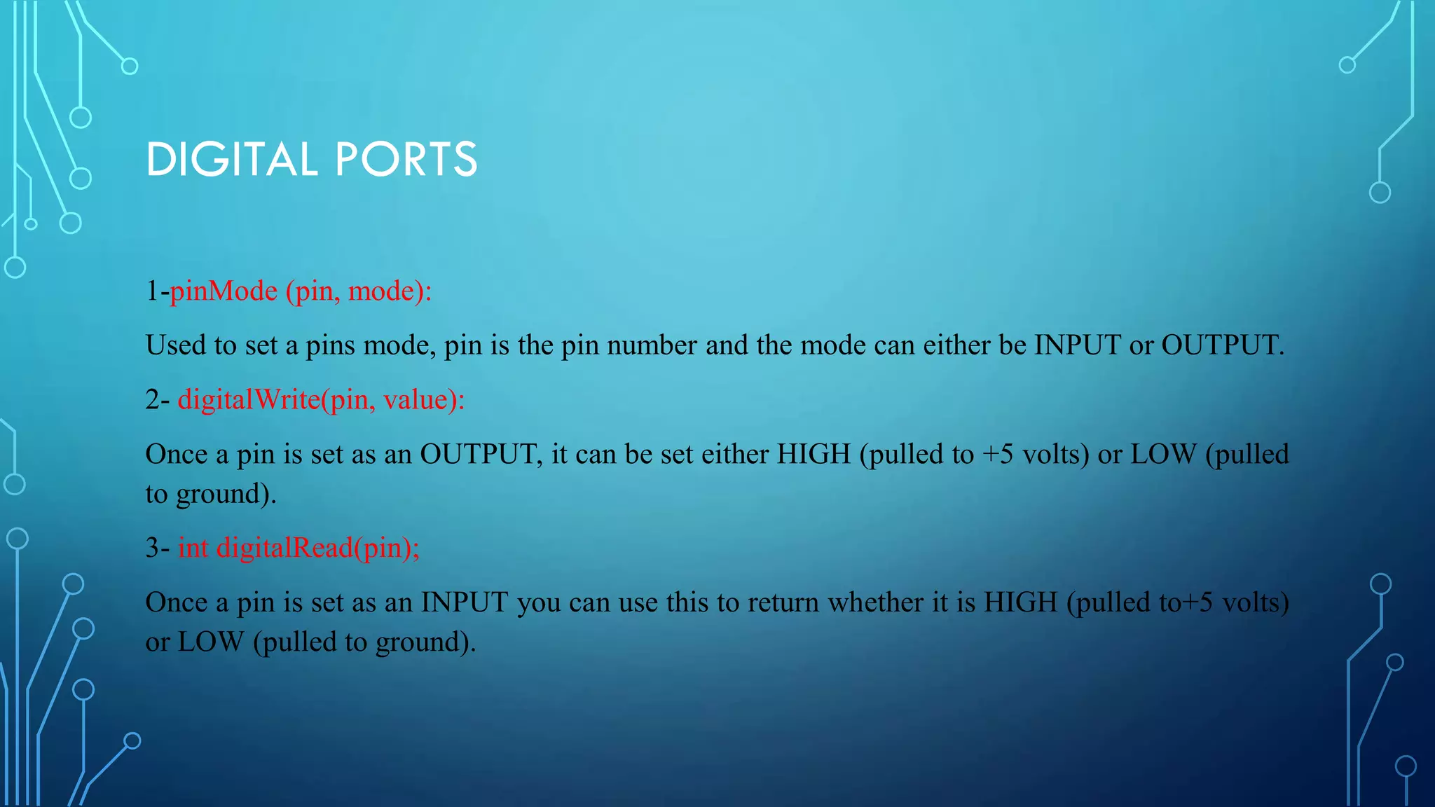
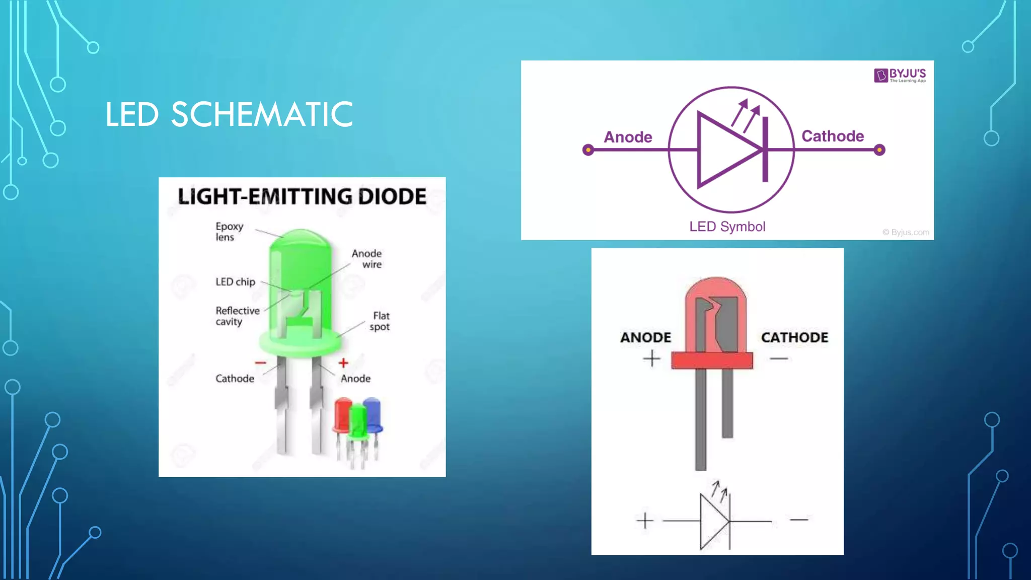
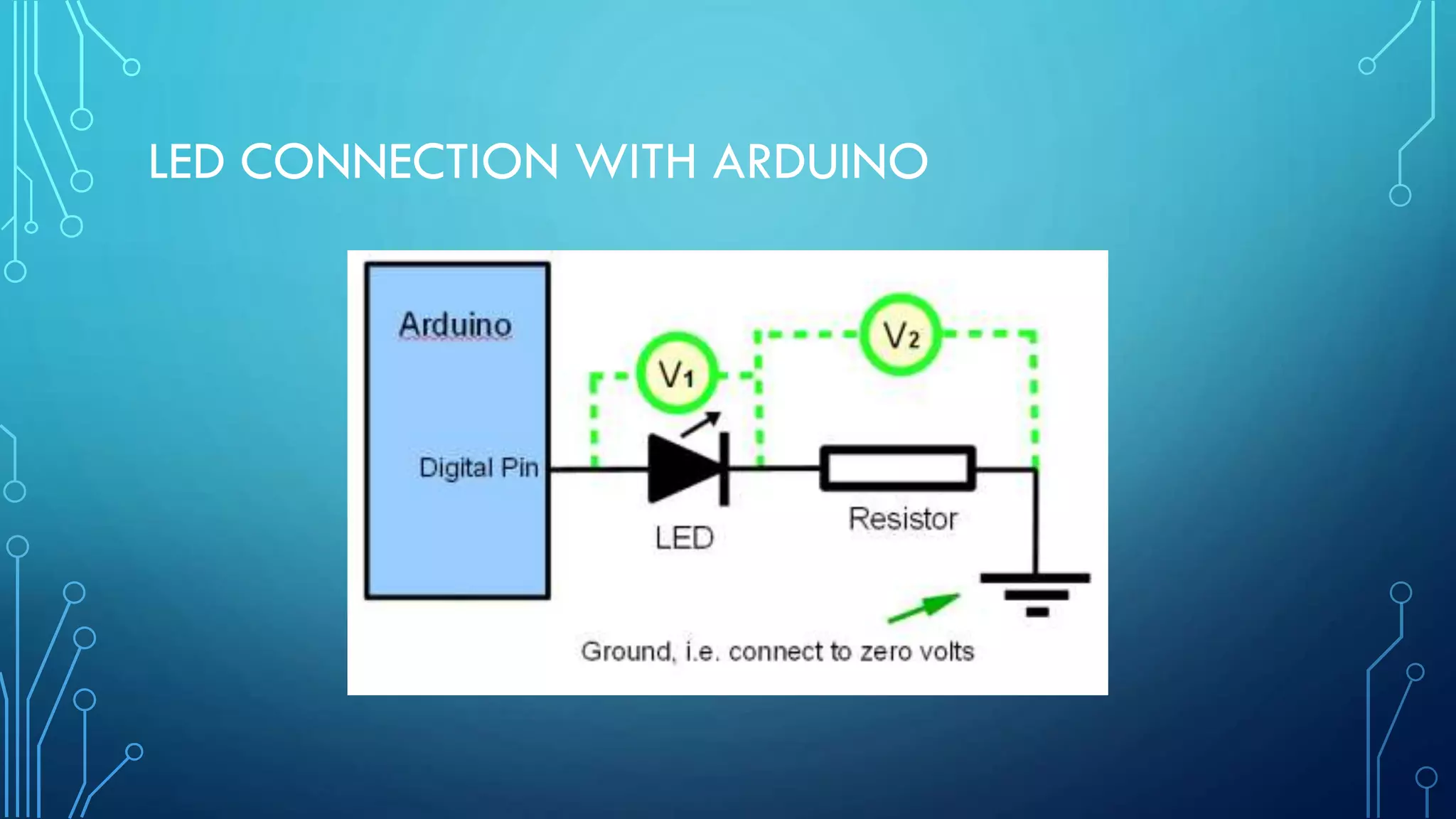
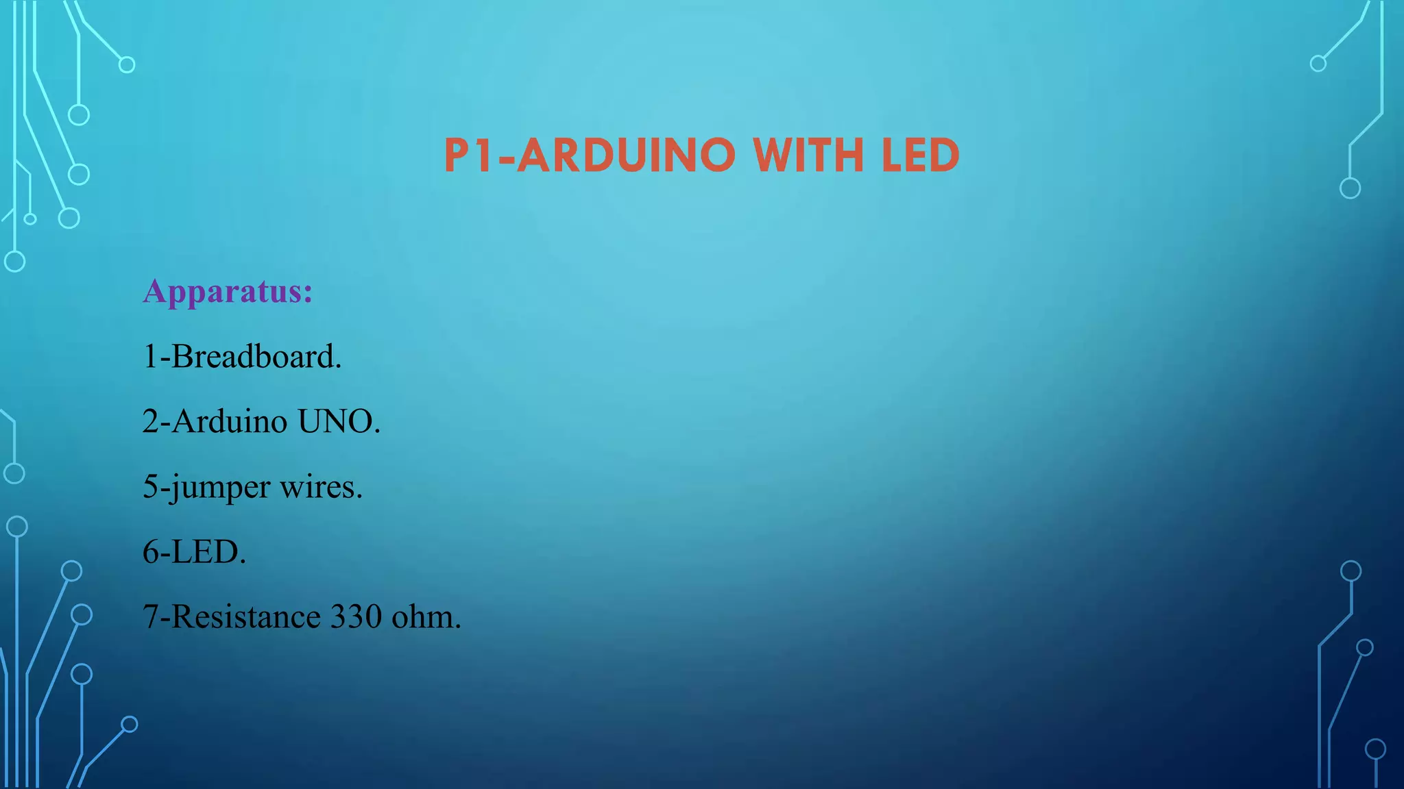
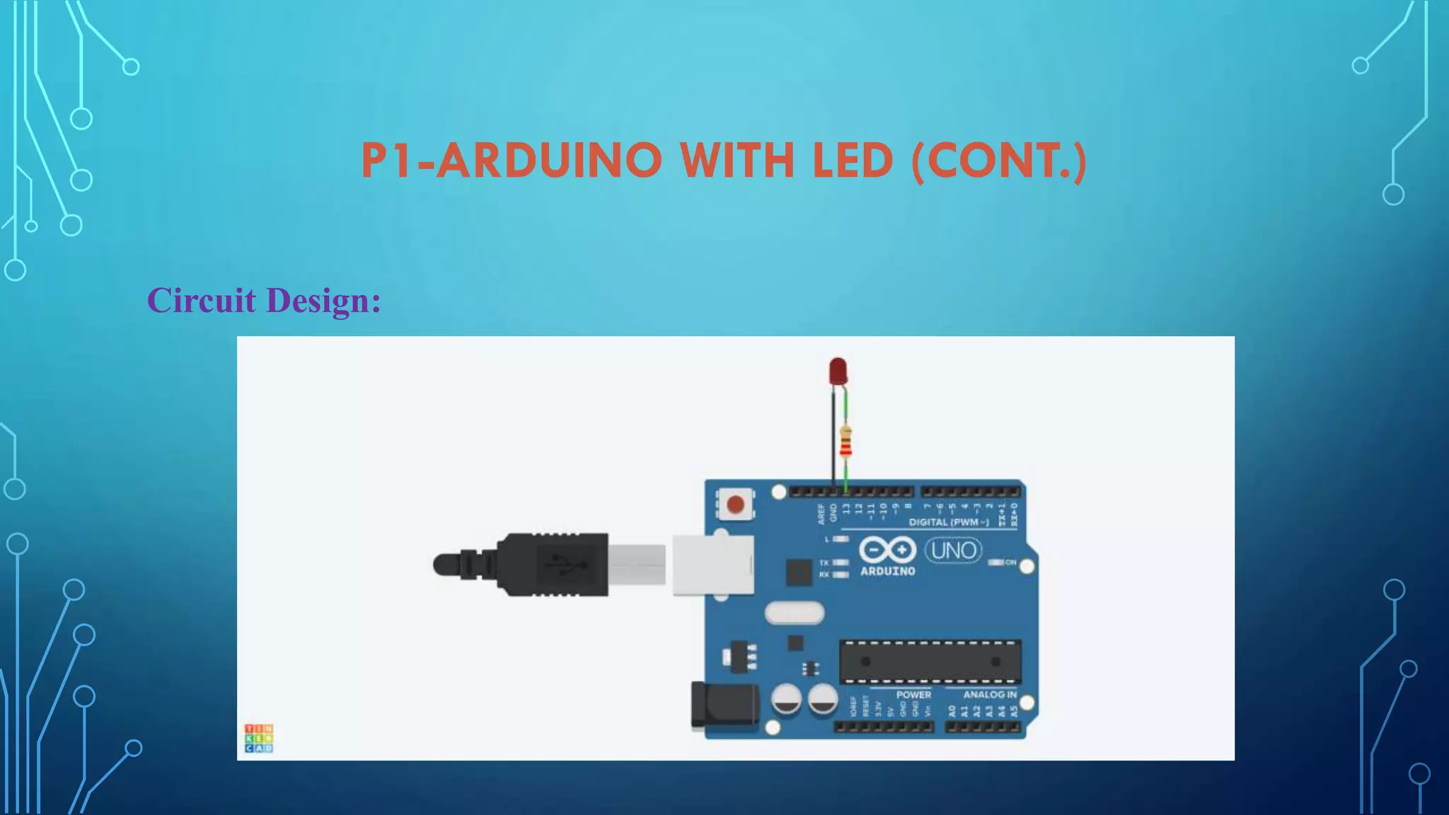
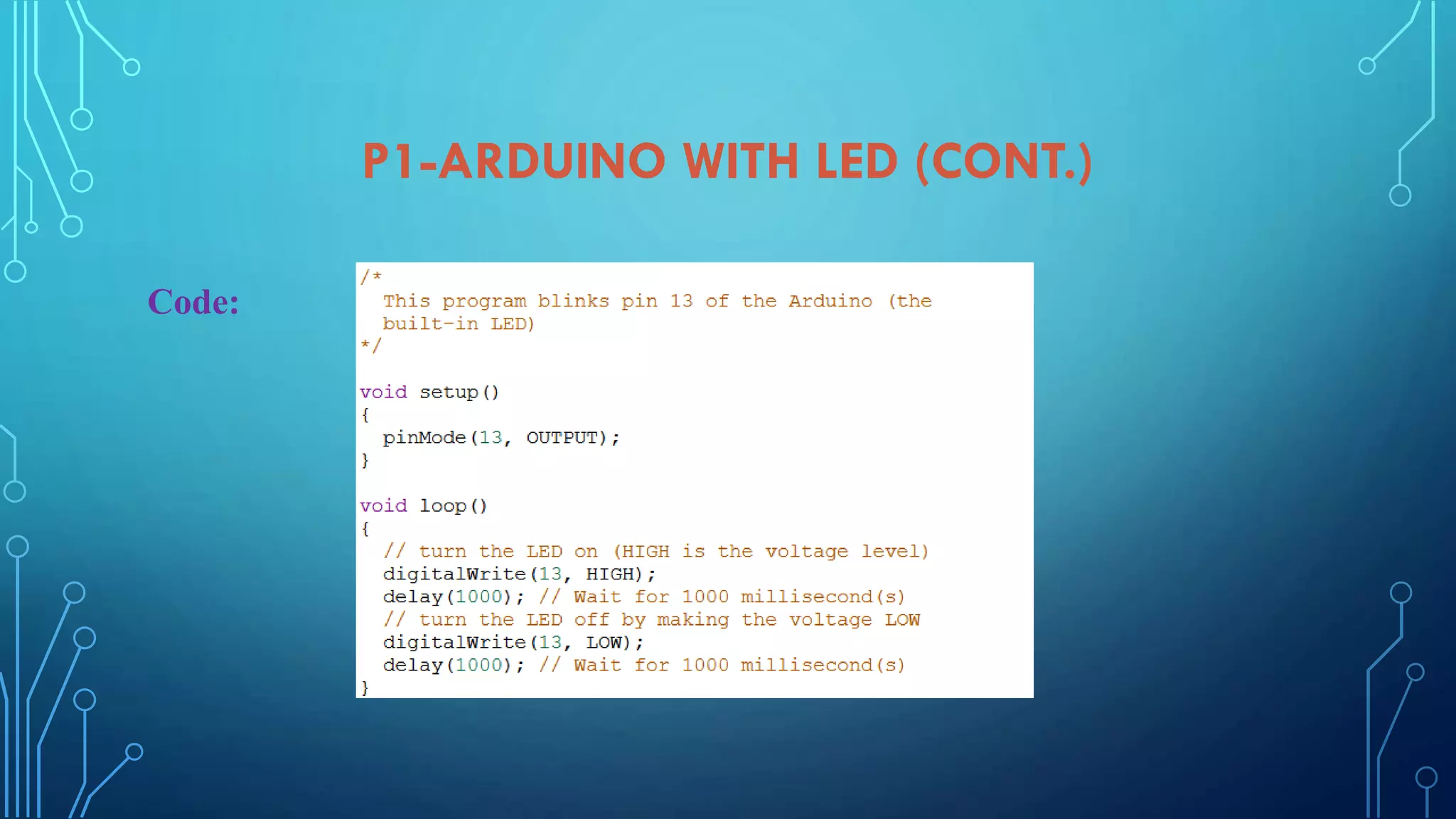
LED project details including digital ports configurations, circuit design, and coding instructions.
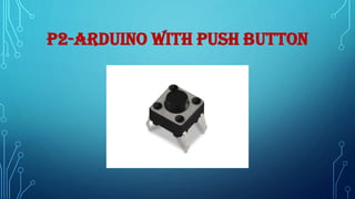
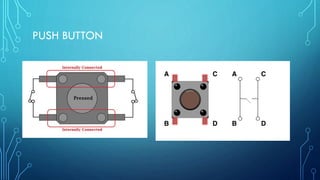
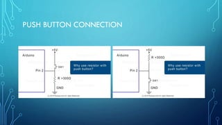
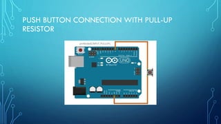
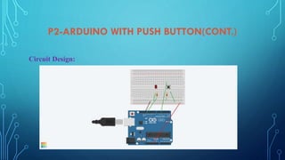
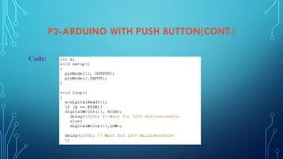
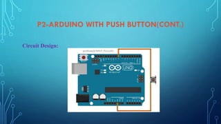
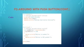
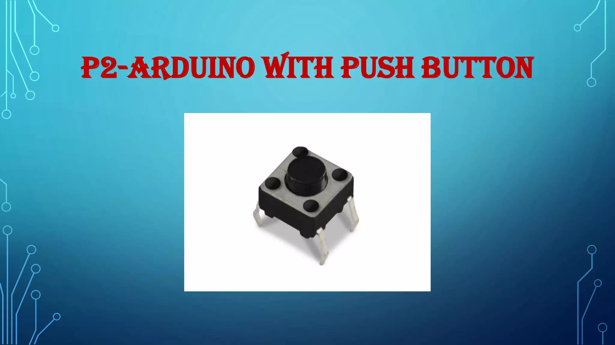
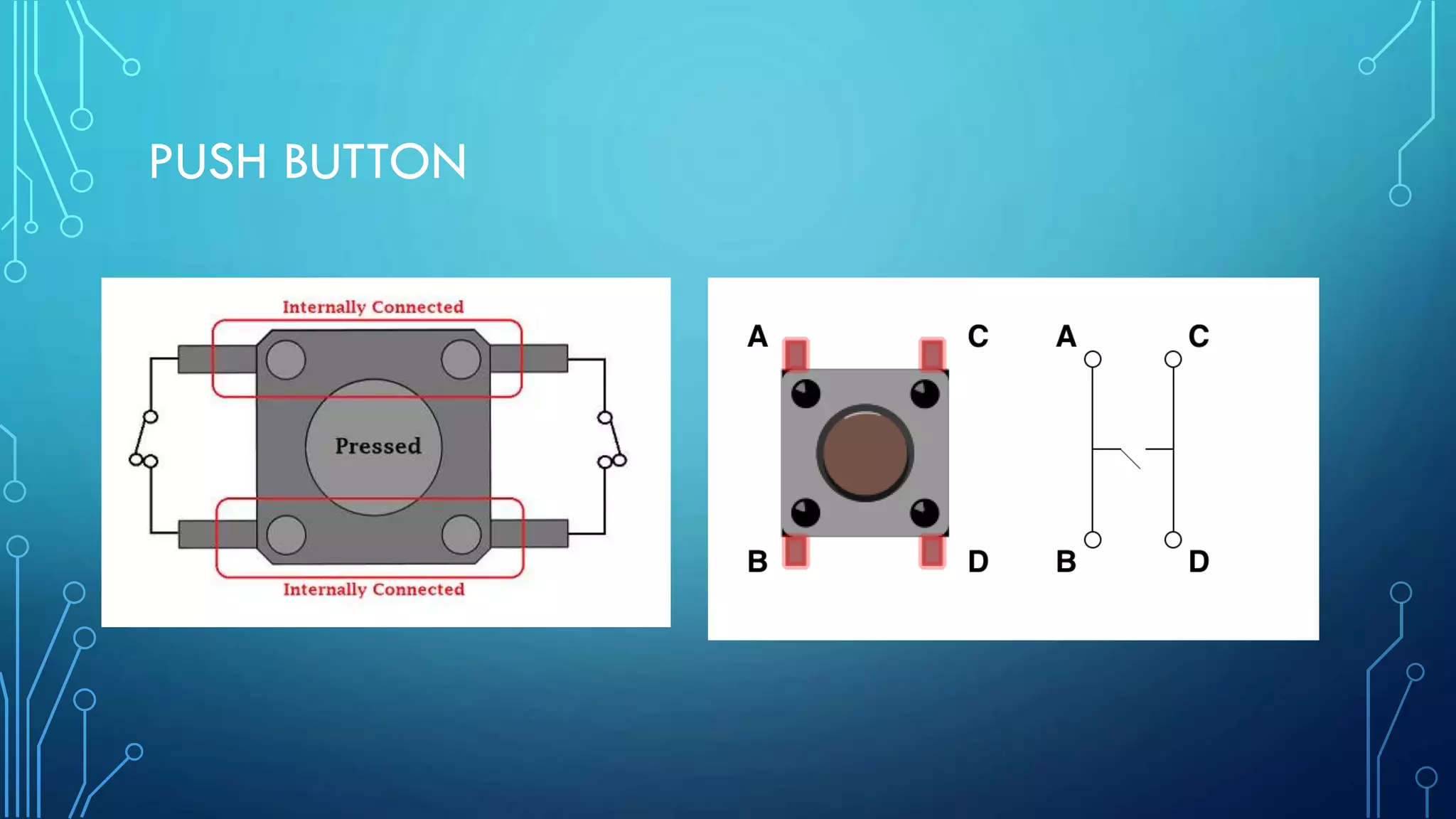
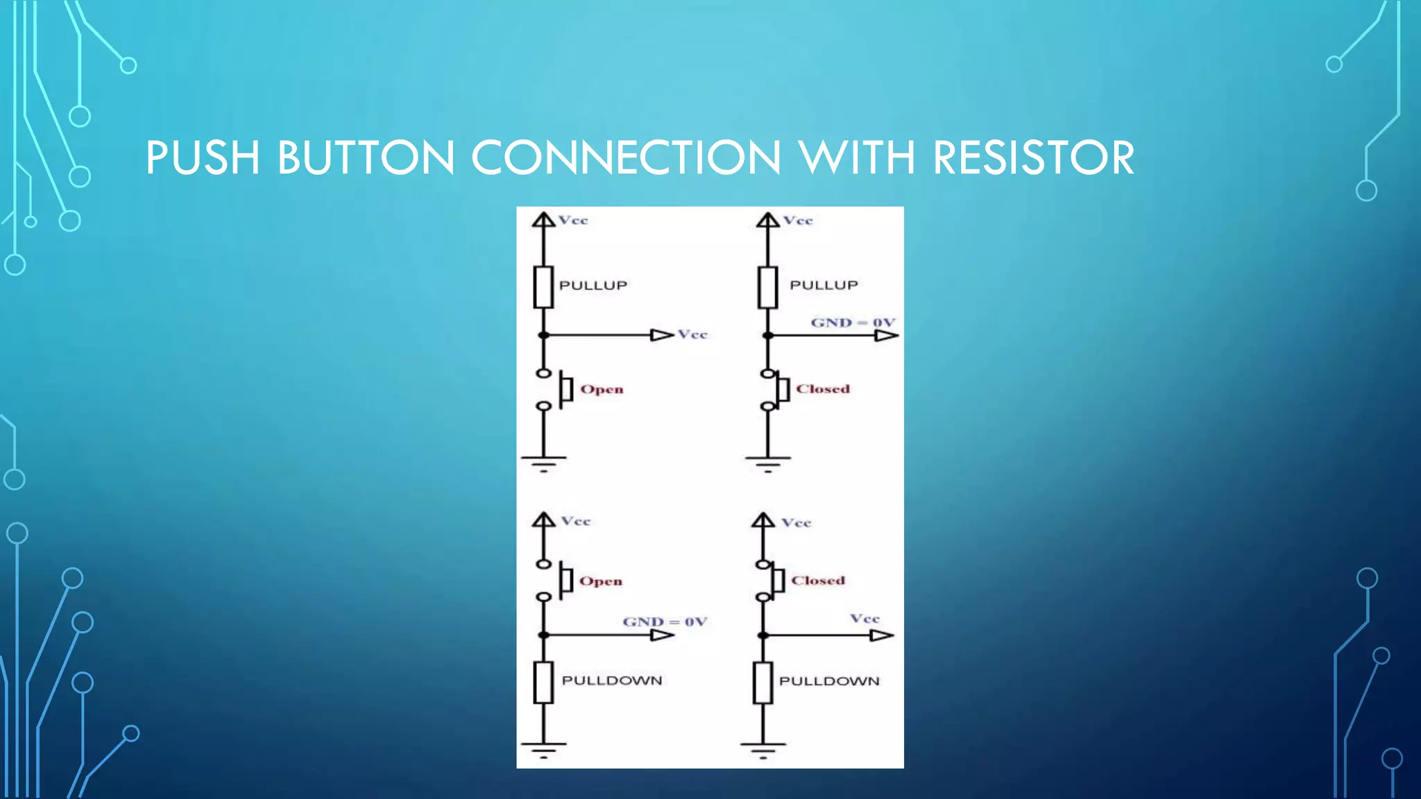
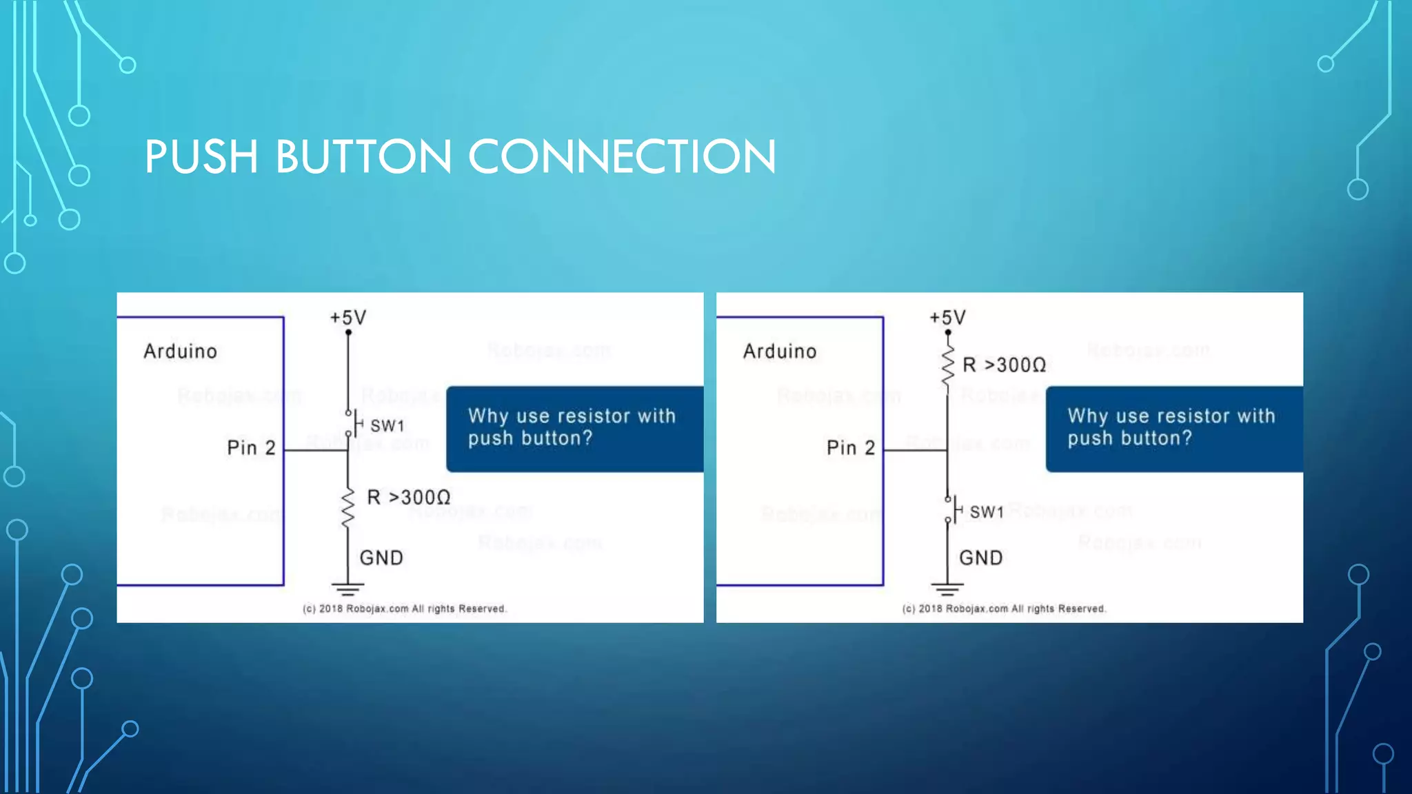
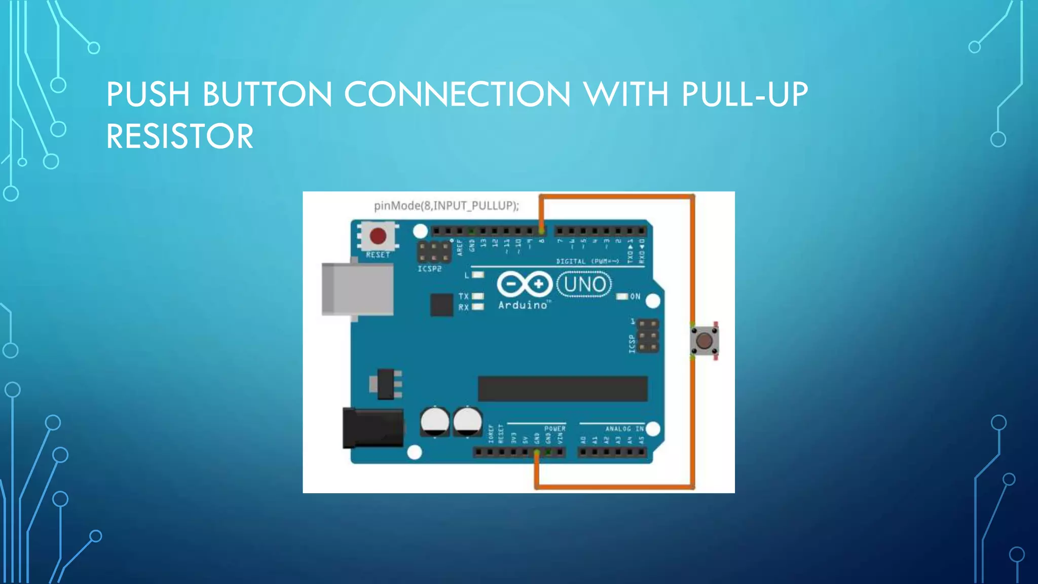
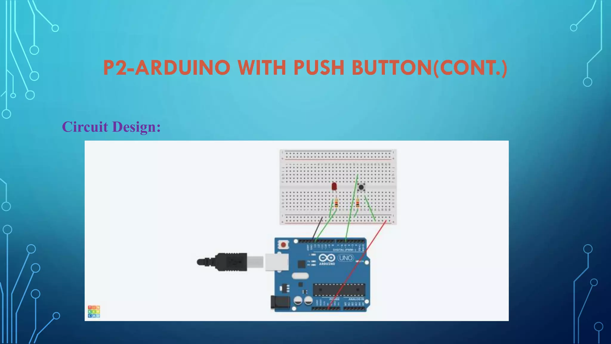
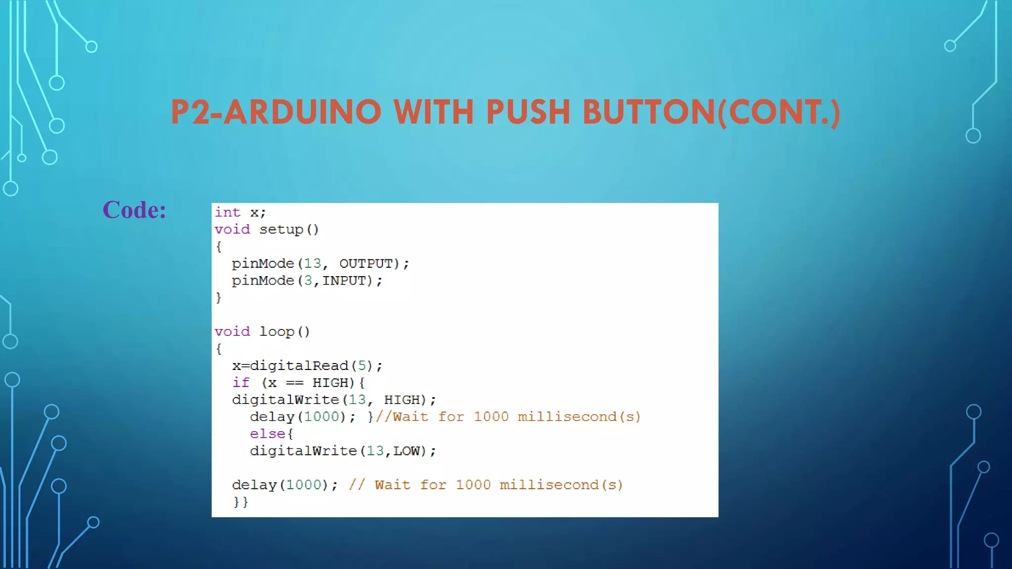
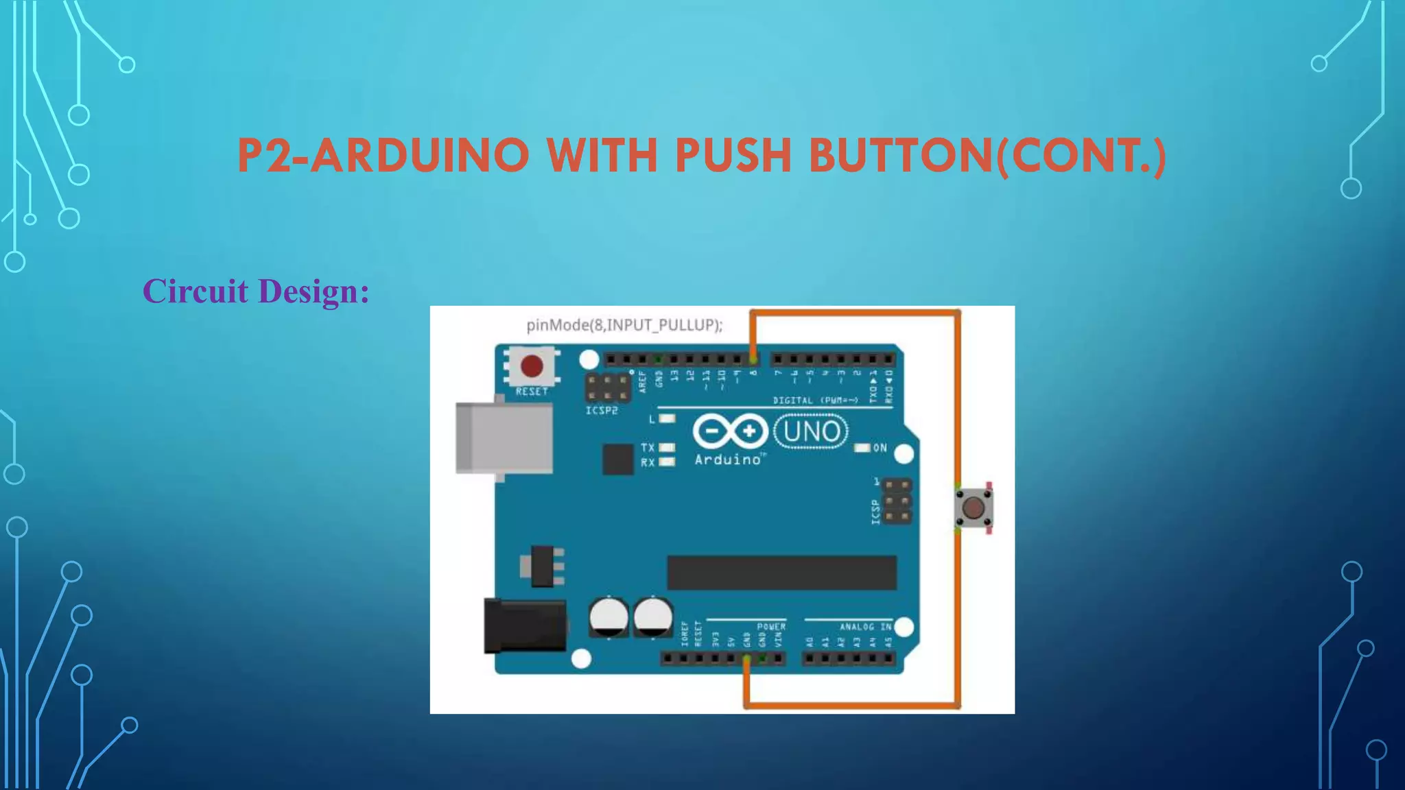
Implementing push button with Arduino, wiring diagrams, and coding for push button functionality.
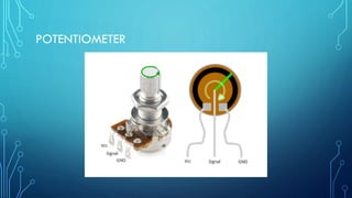
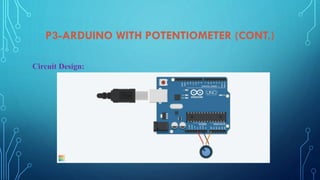
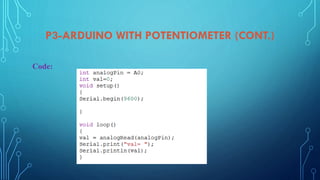
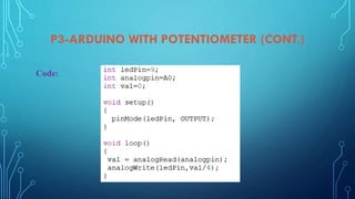
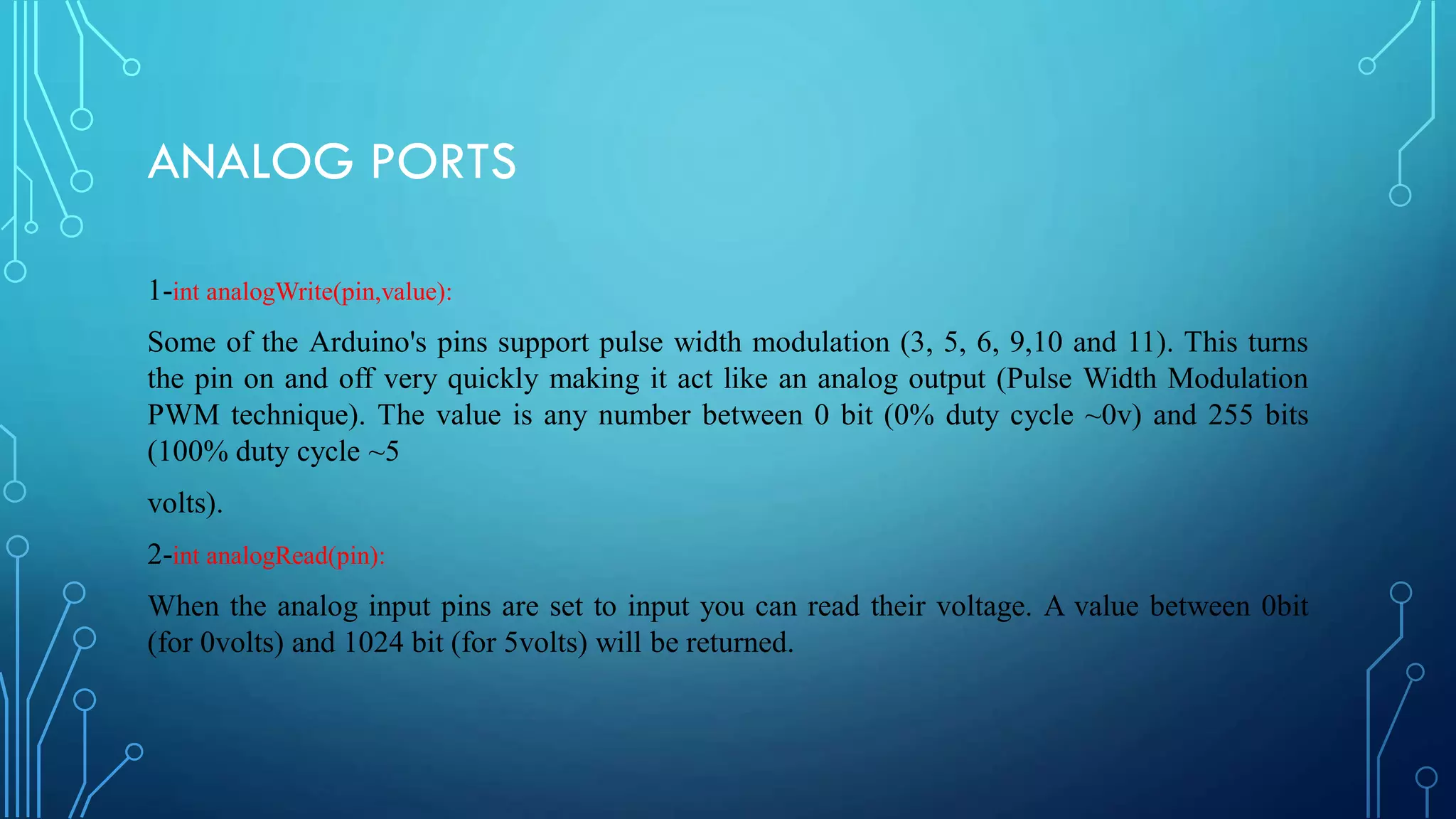
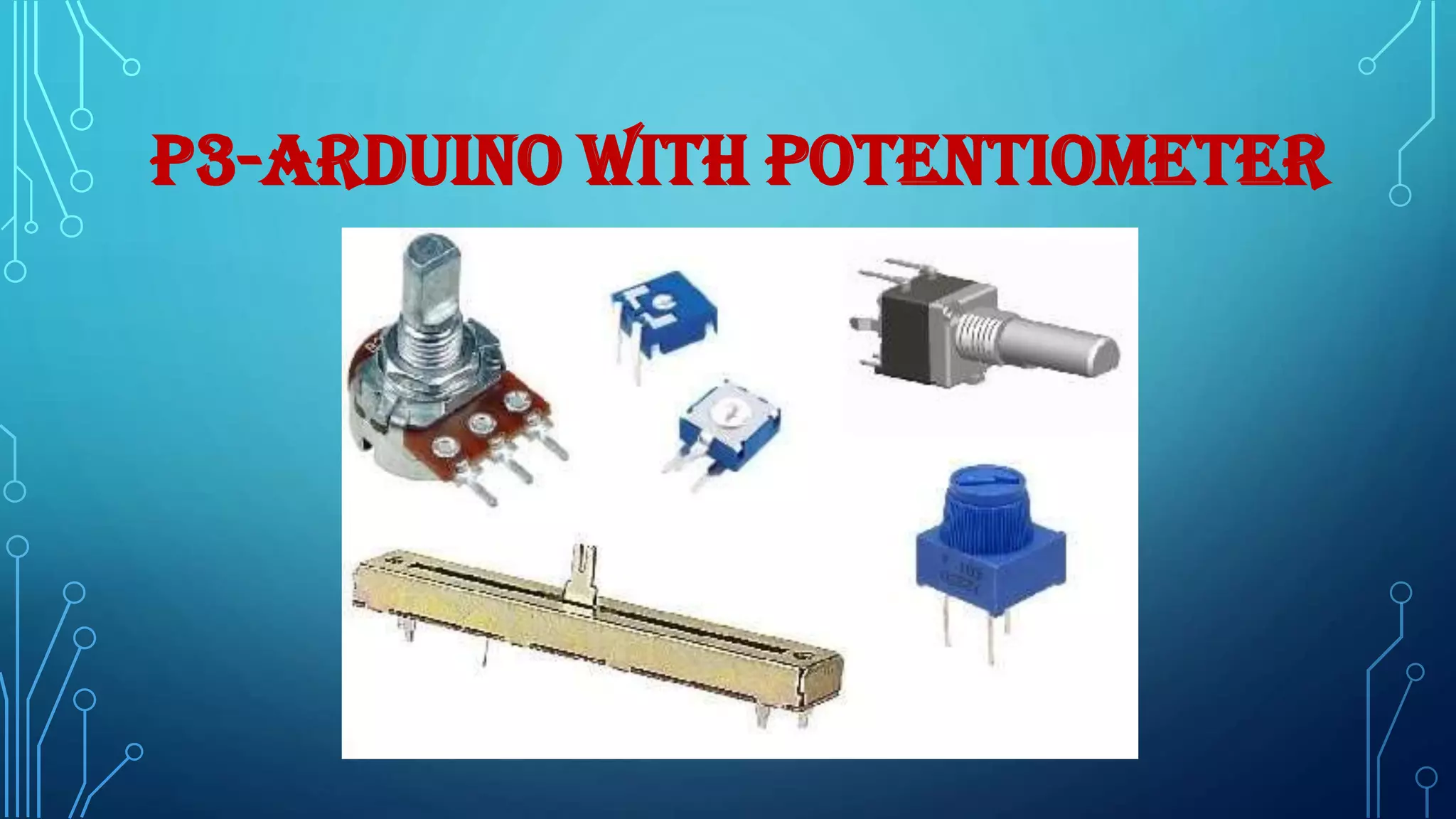
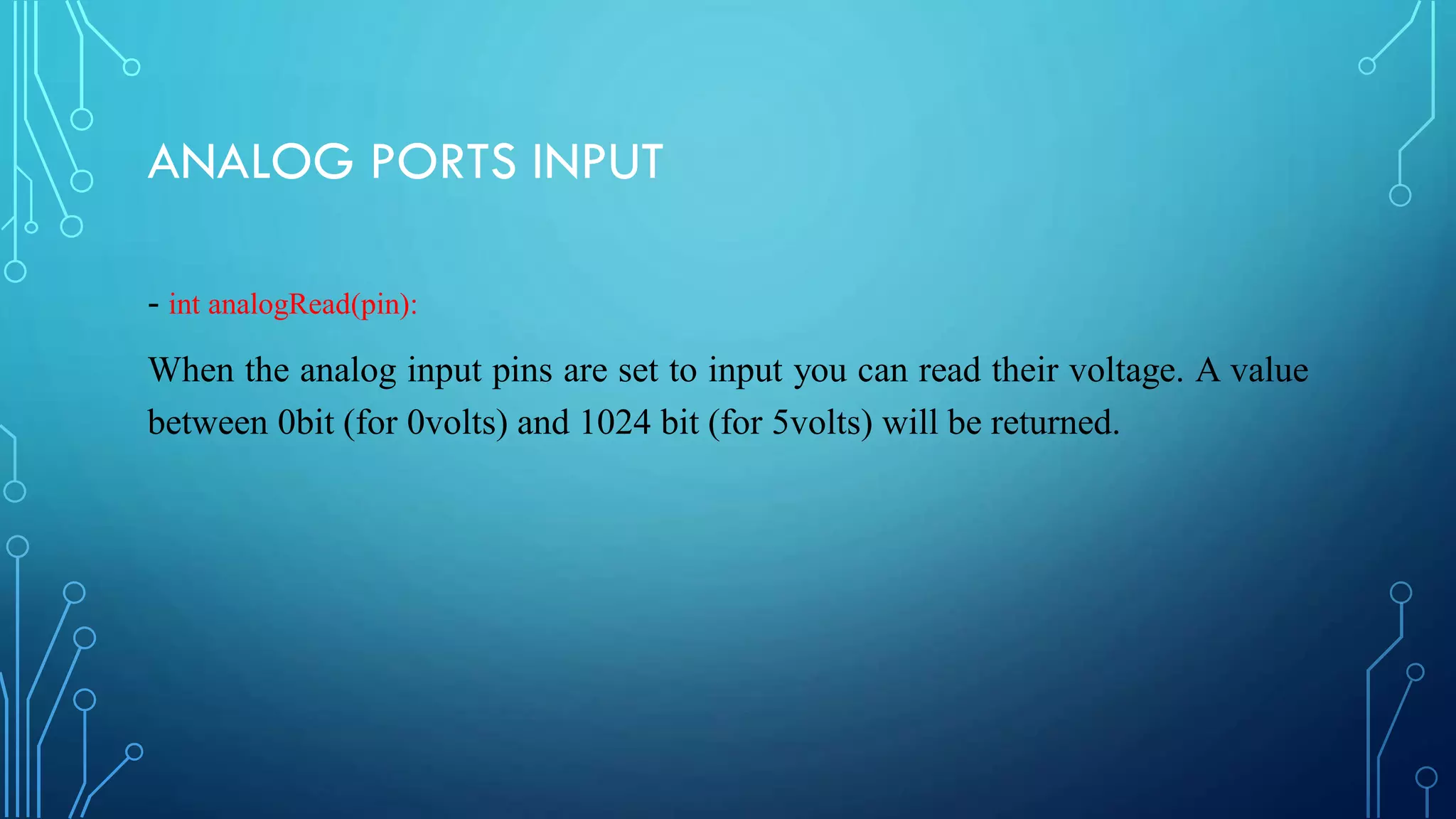
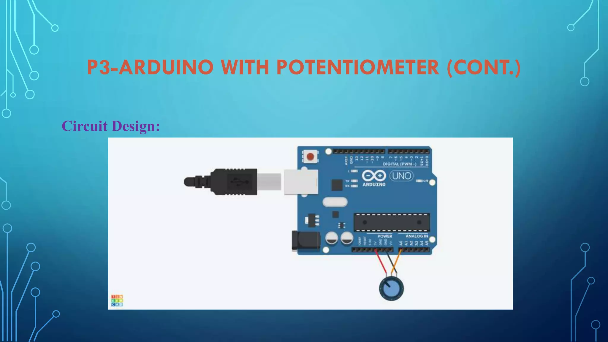
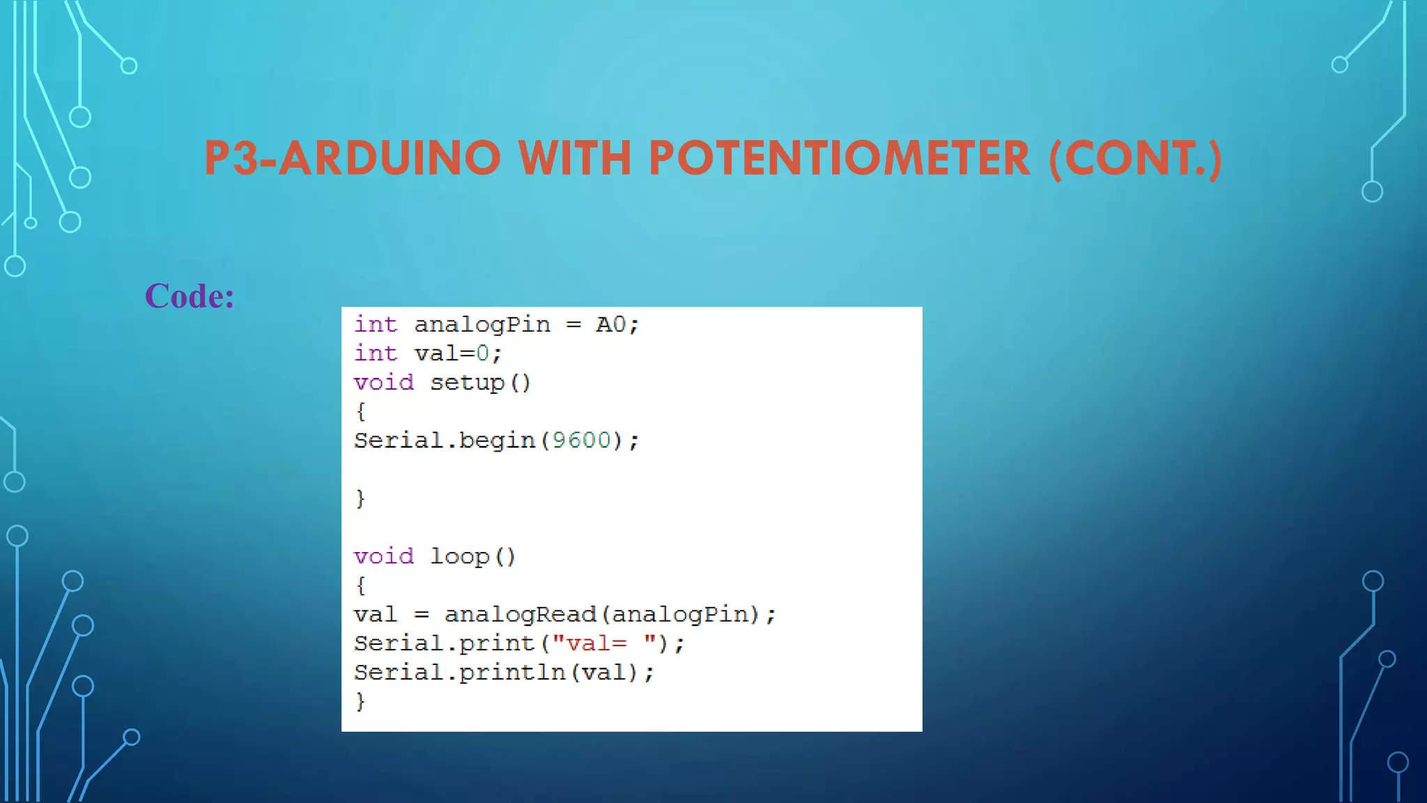
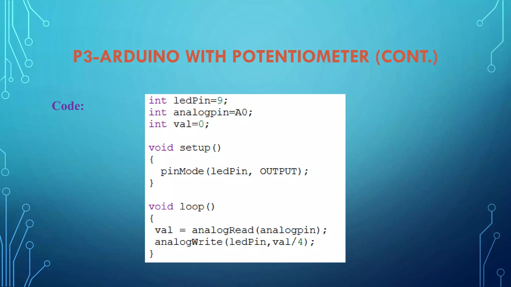
Connecting and coding a potentiometer with Arduino, including analog input readings and circuit design.
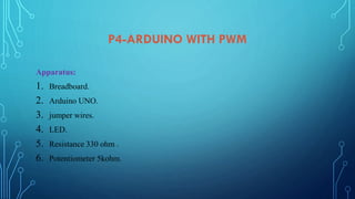
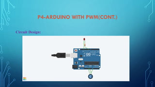
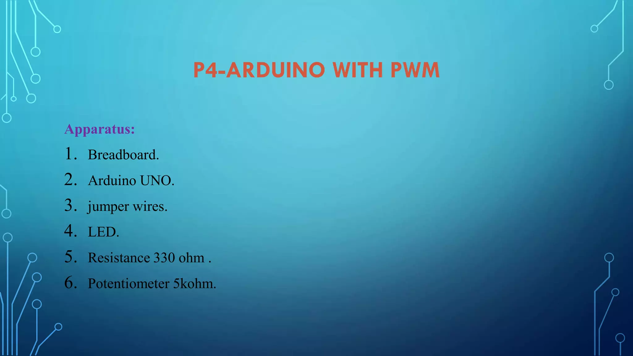
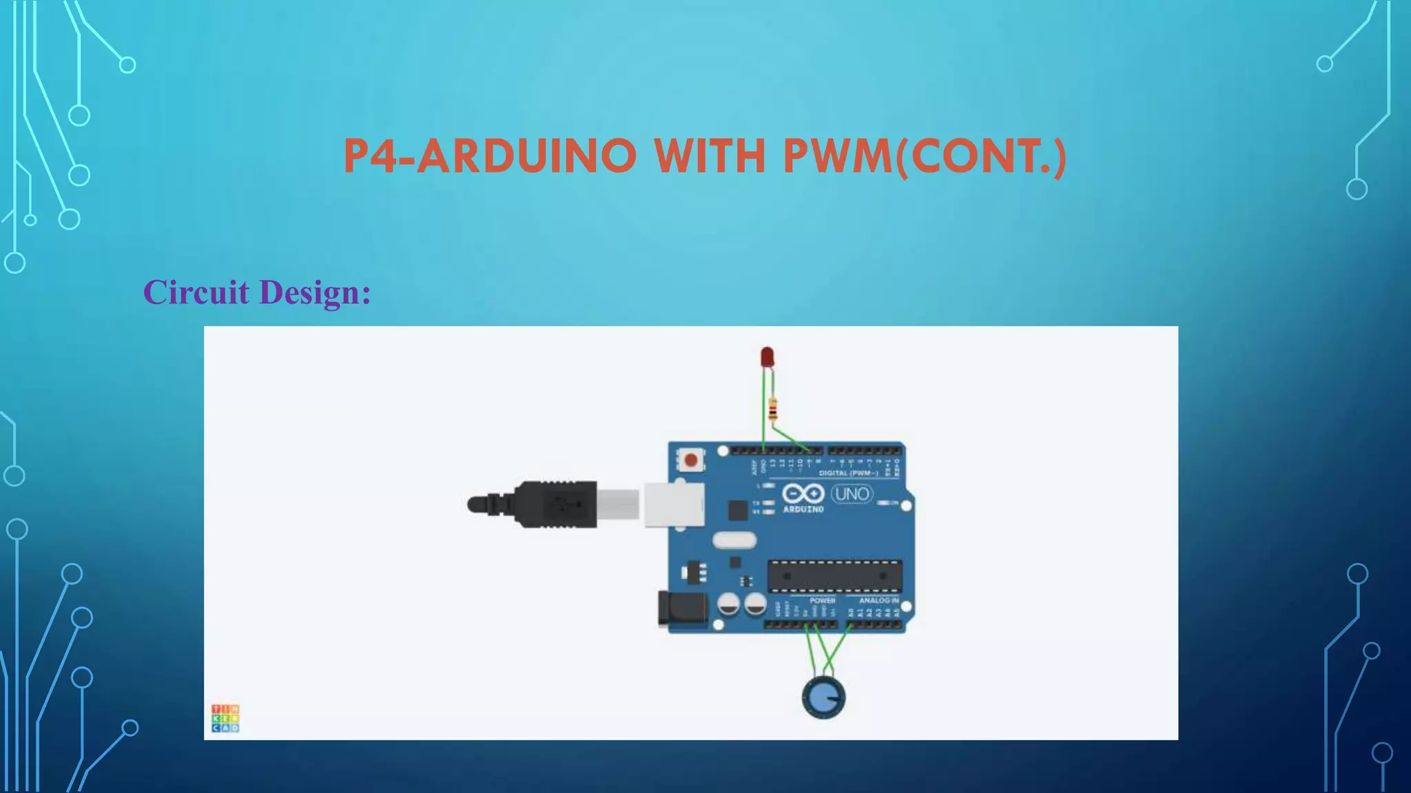
Concept and application of PWM in Arduino, including circuit design and code for controlling outputs.
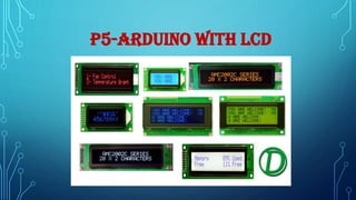
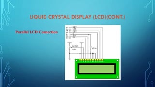
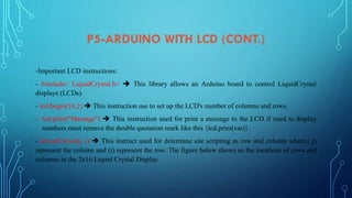
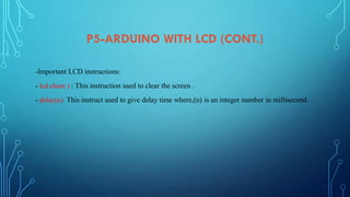
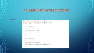
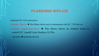
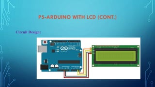
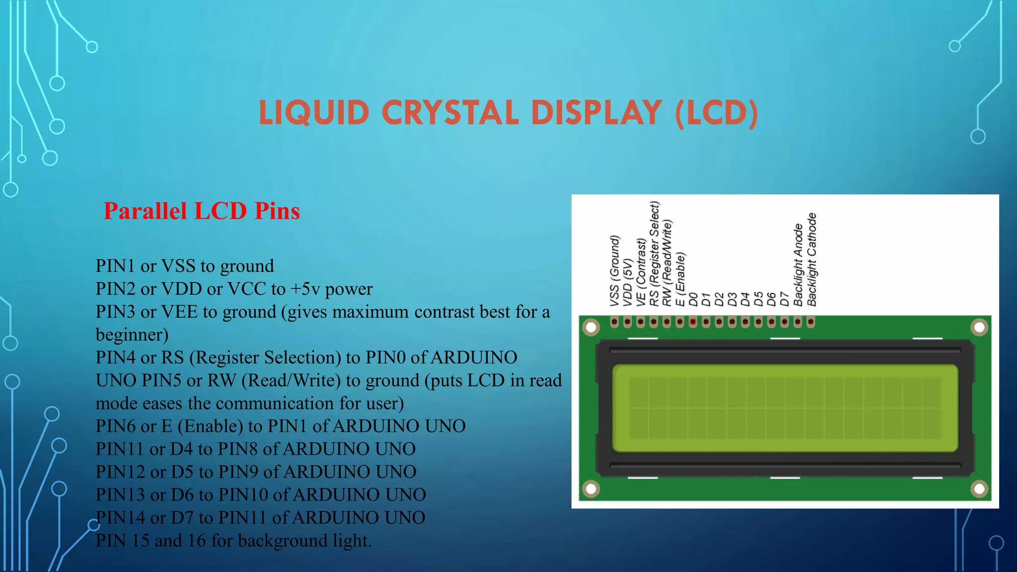
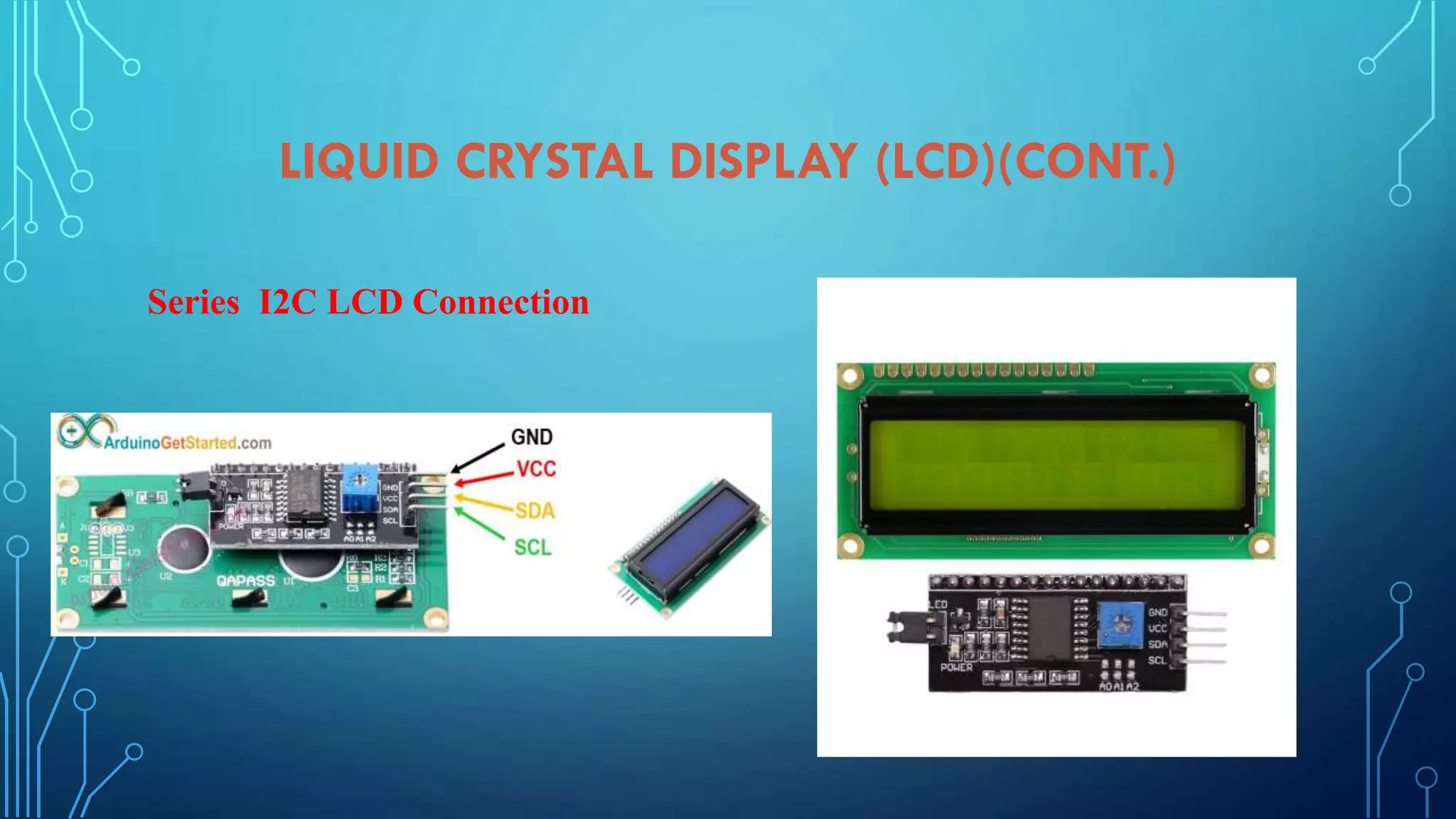
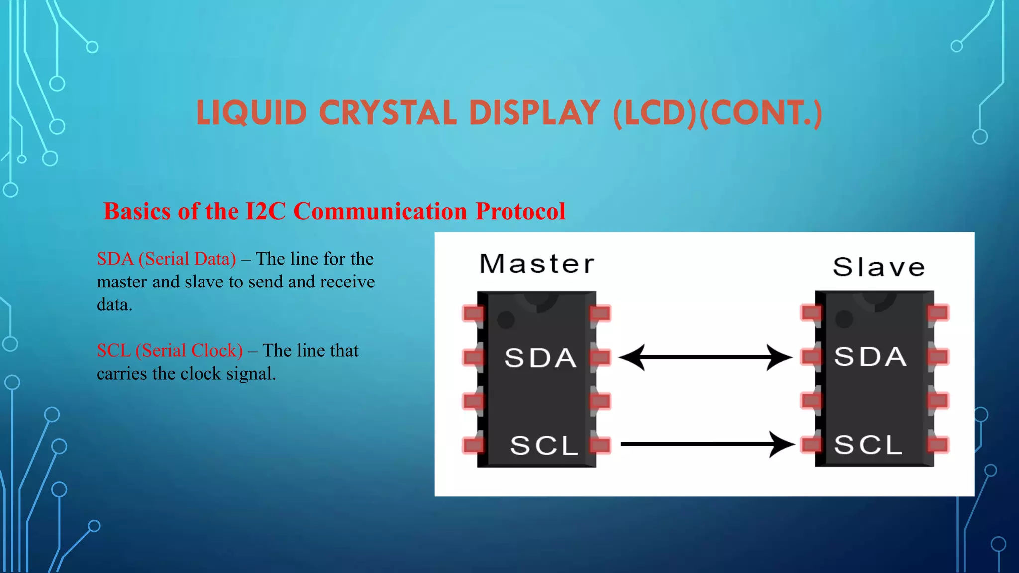
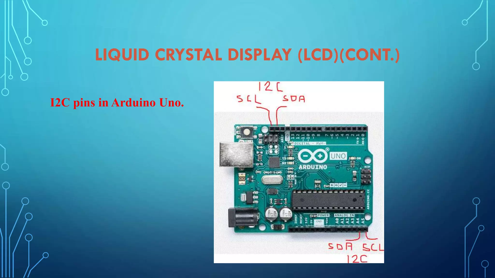
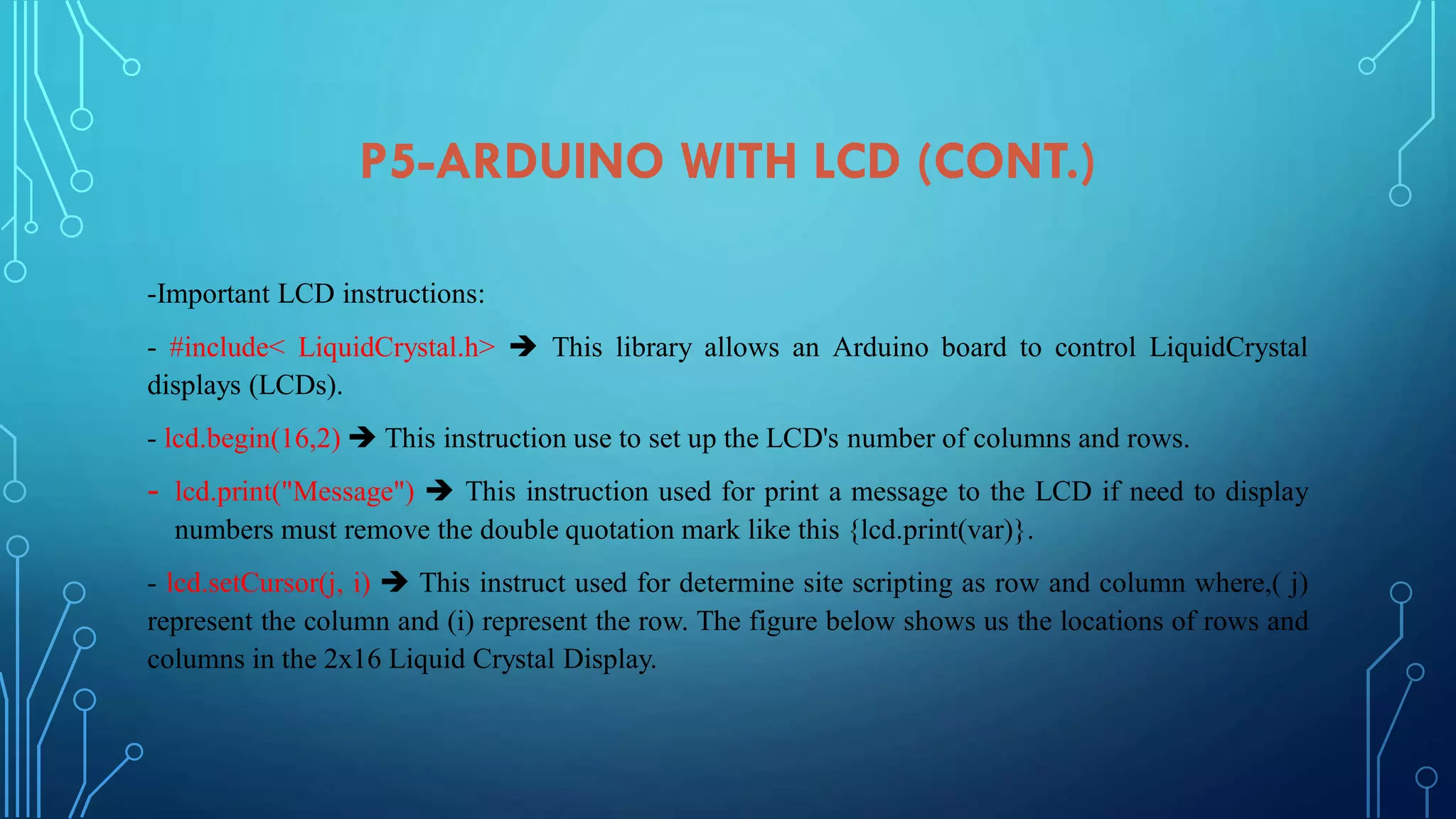
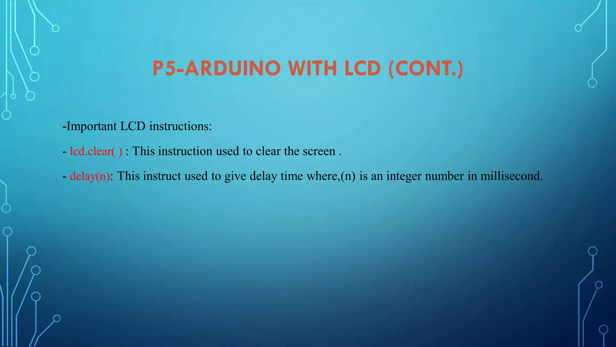
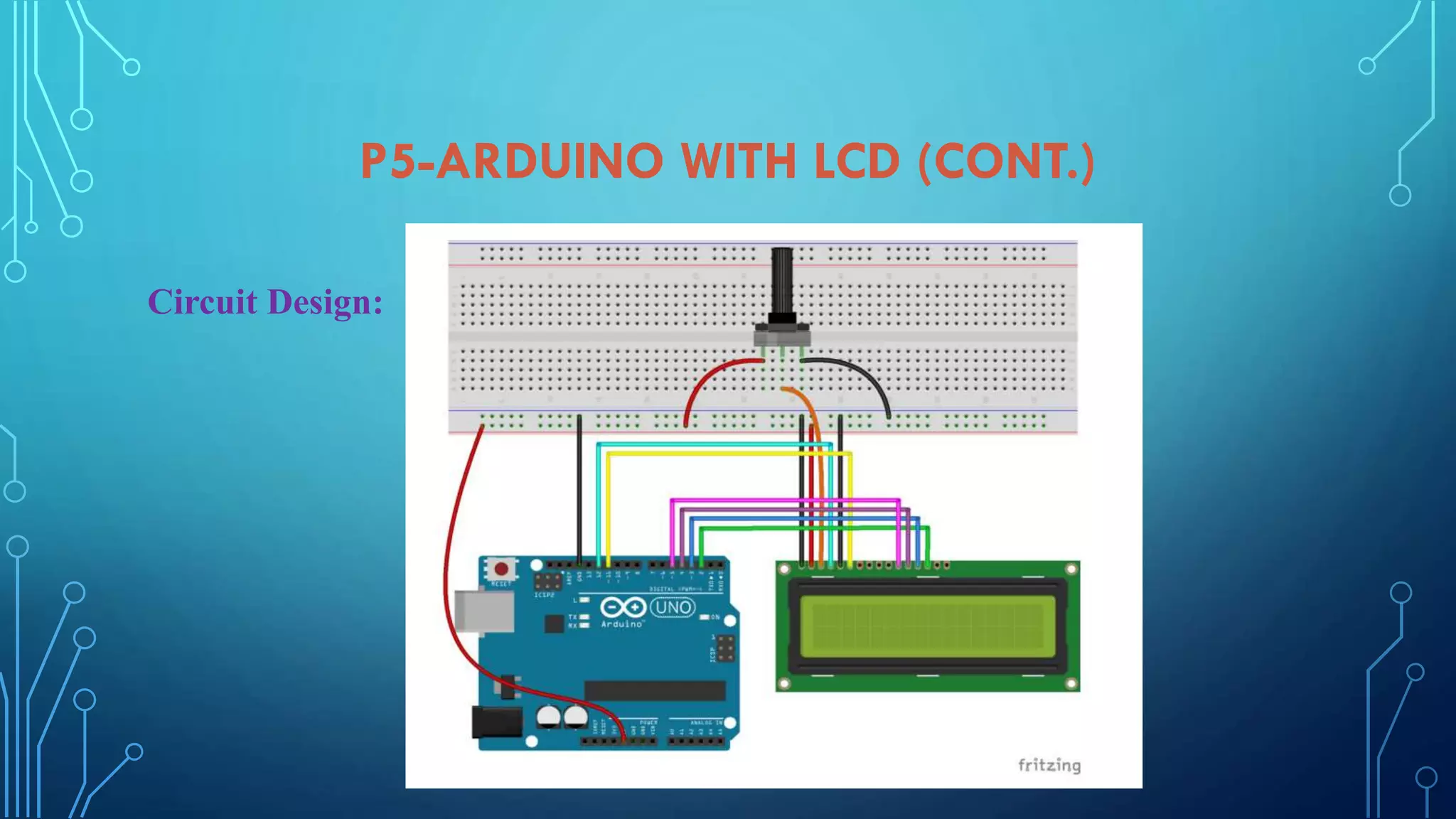
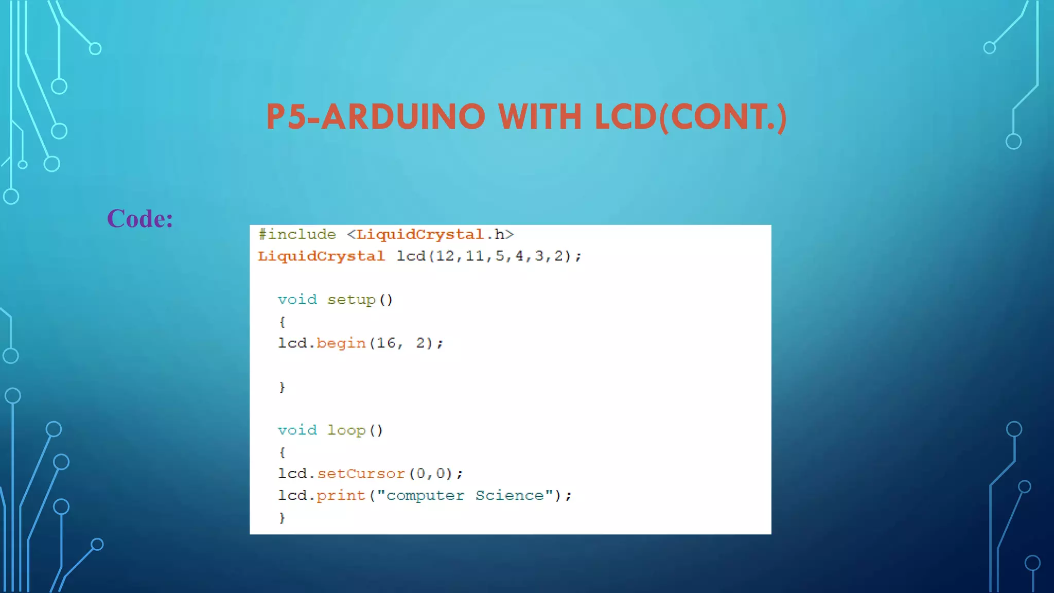
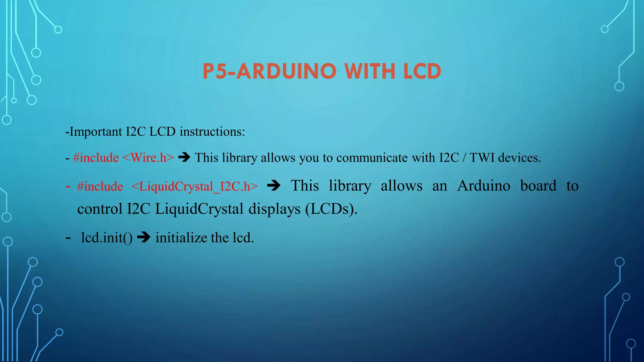
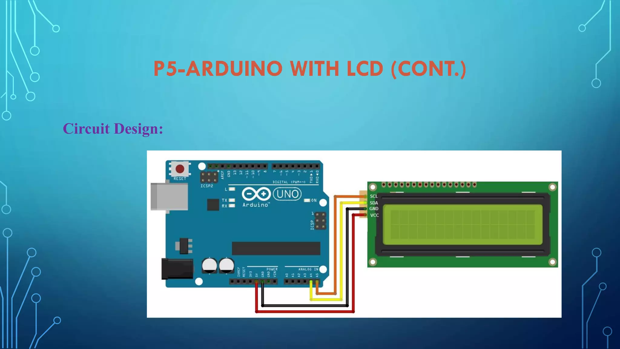
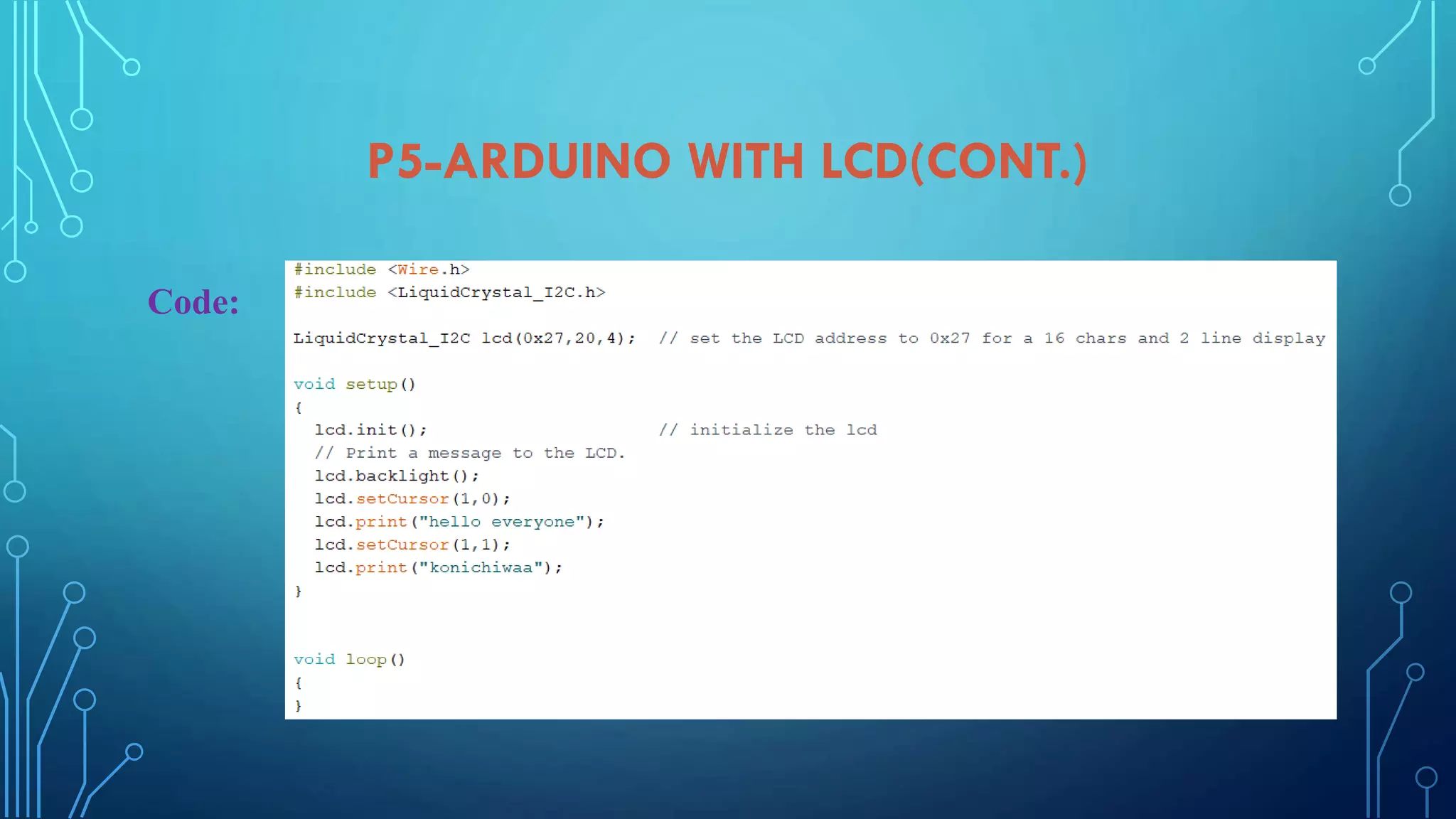
Instructions for connecting and programming an LCD display with Arduino, including circuit and library usage.
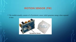
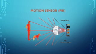
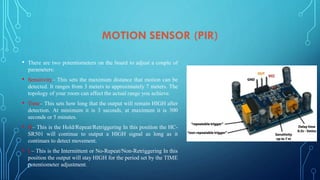
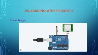
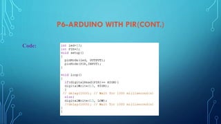
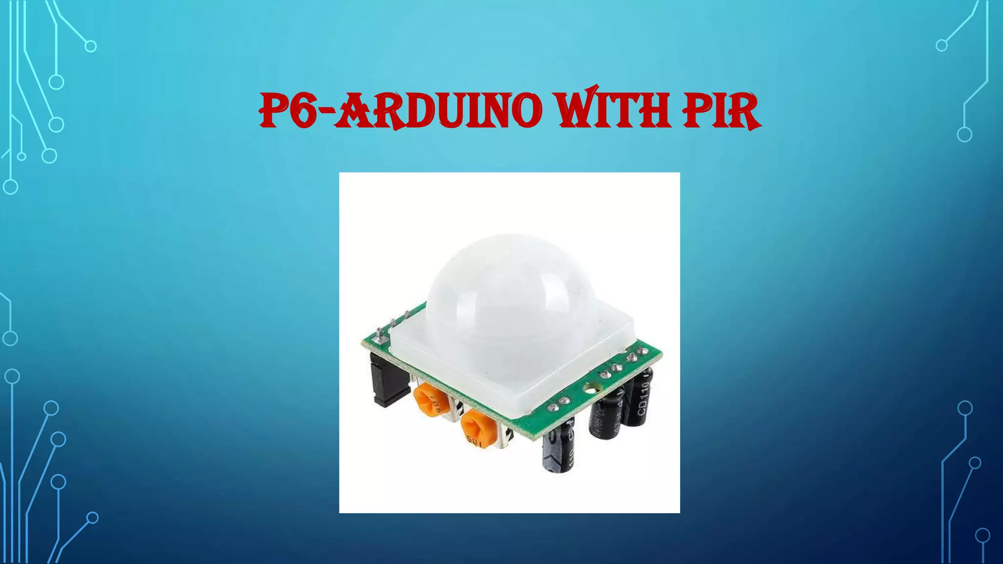
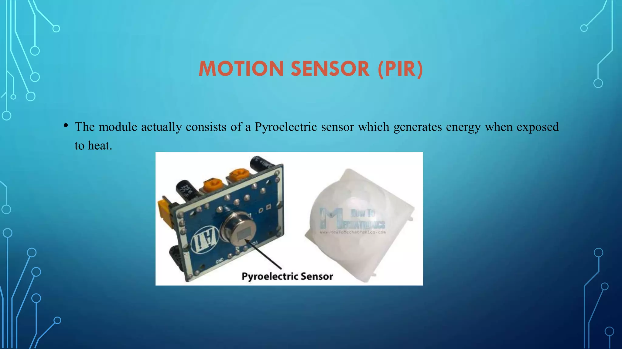
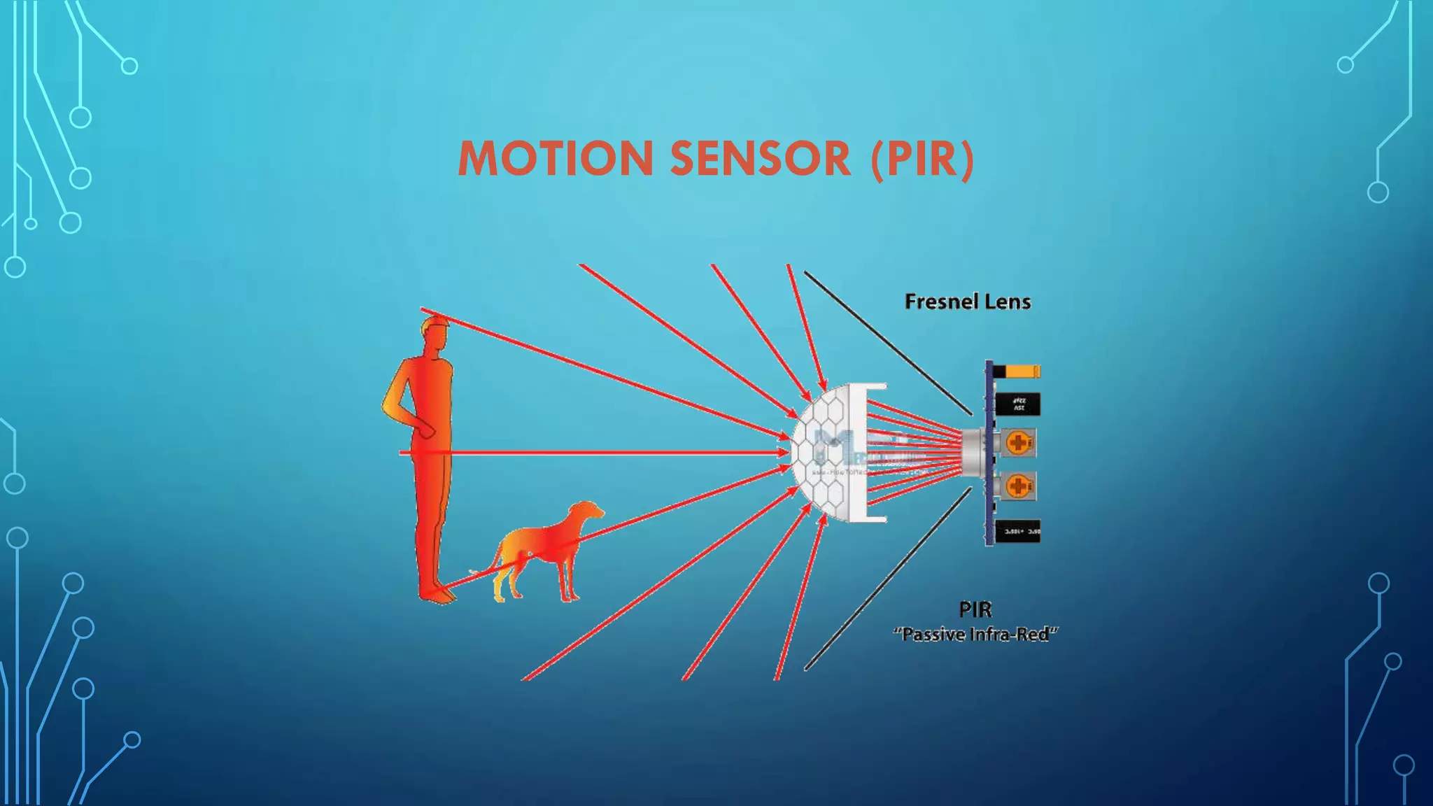
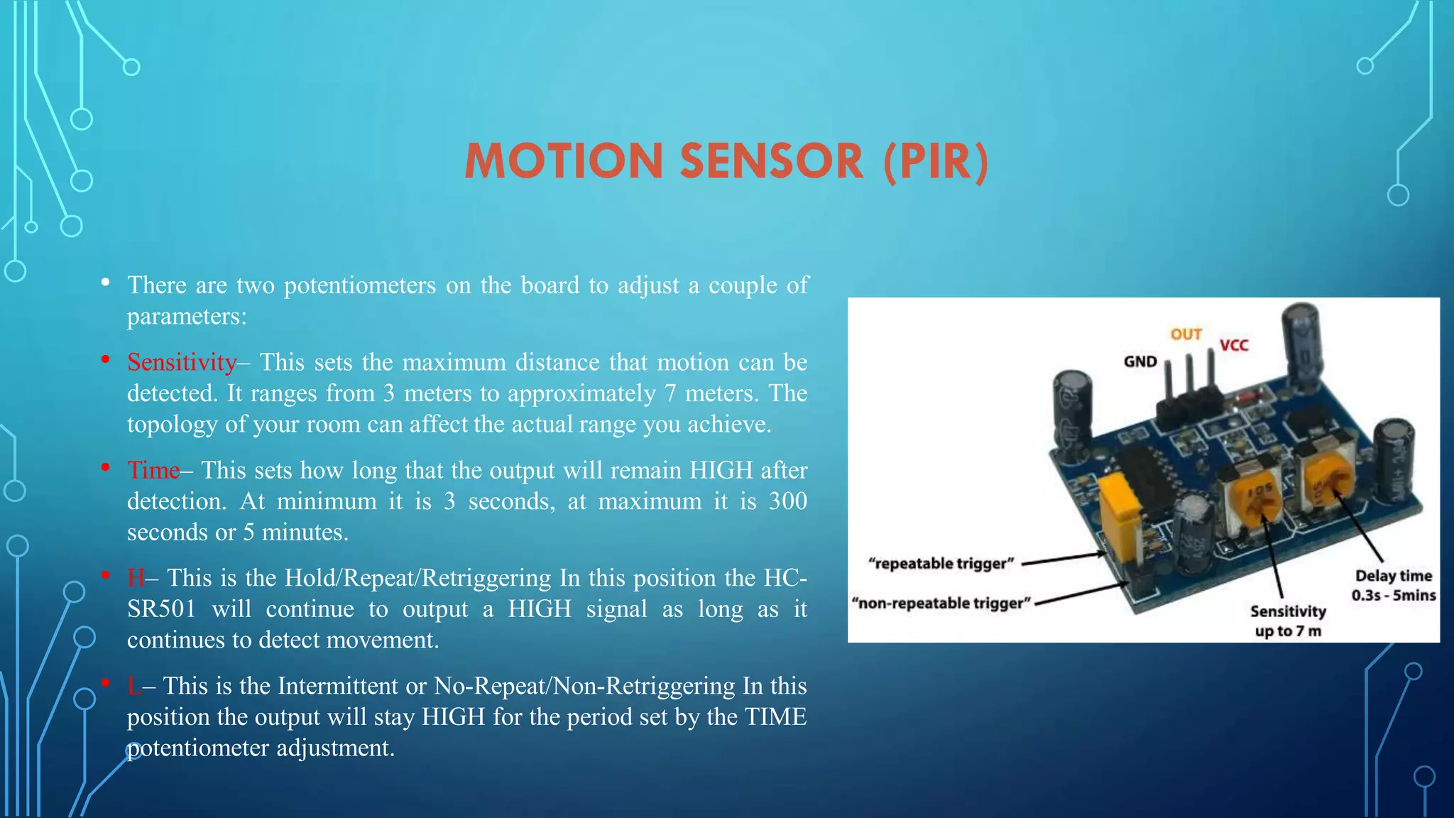
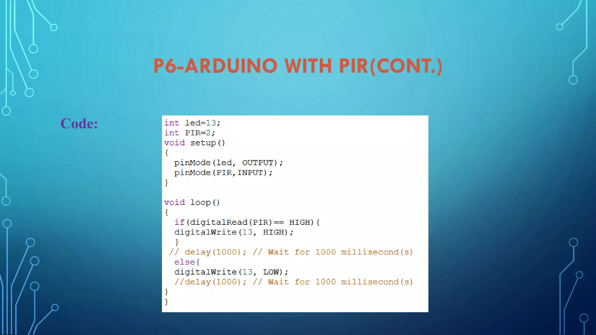
Details on using a PIR motion sensor with Arduino, including sensitivity settings and circuit design.
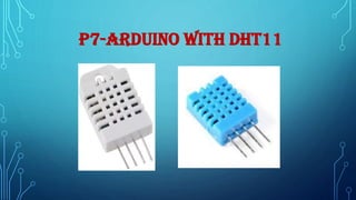
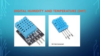
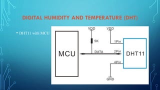
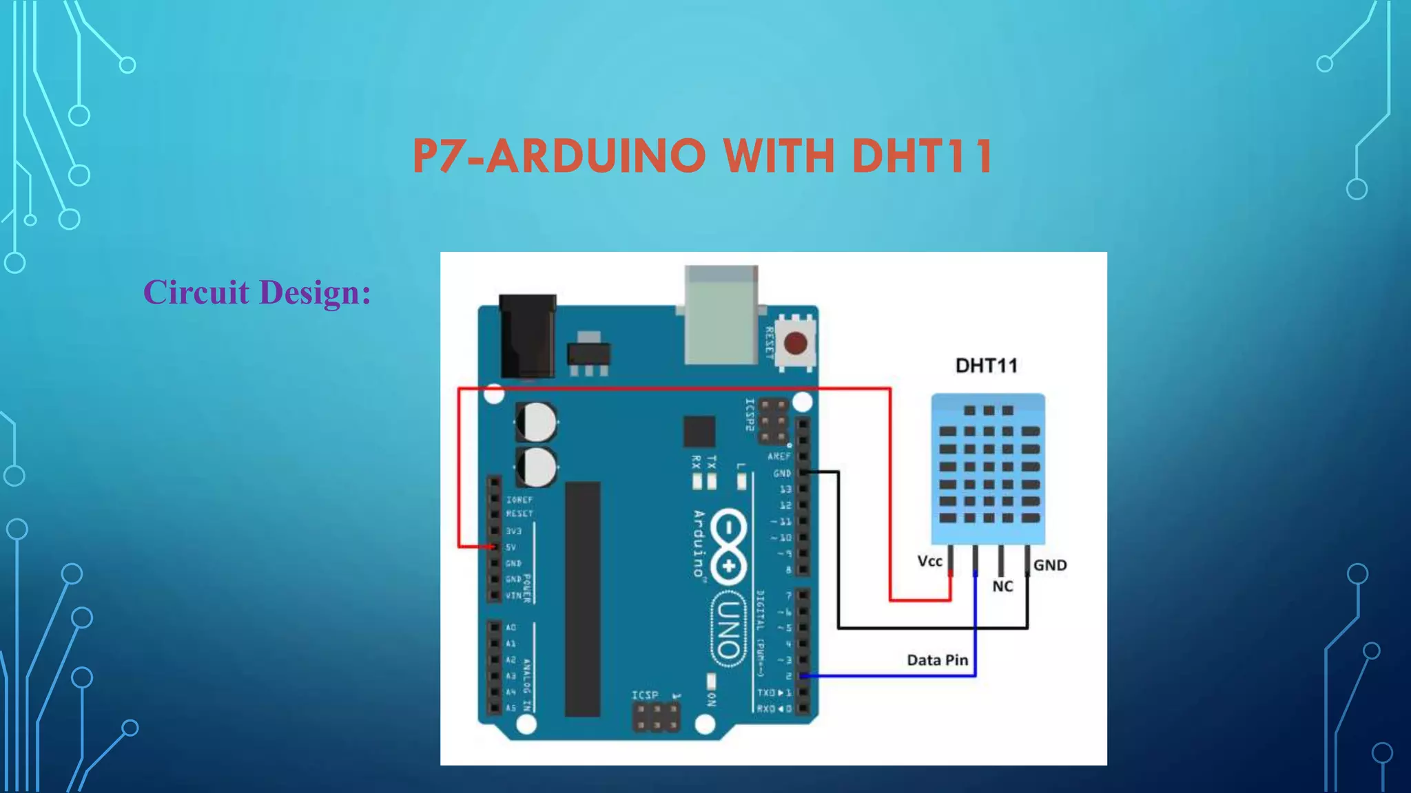
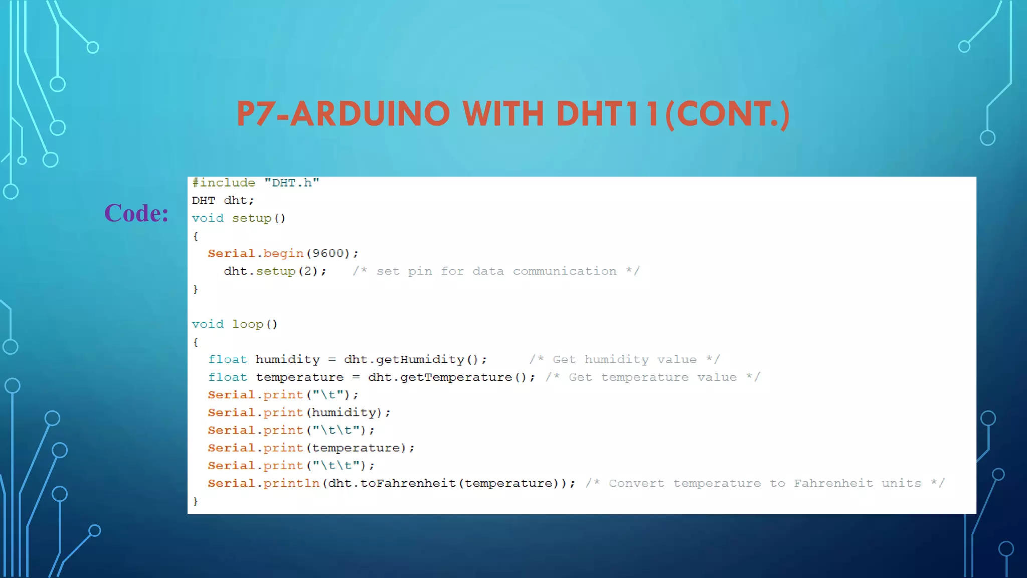
Implementing DHT11 sensor for humidity and temperature readings along with circuit design and code.
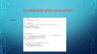
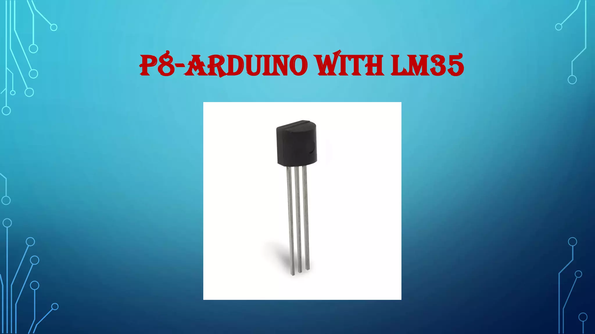
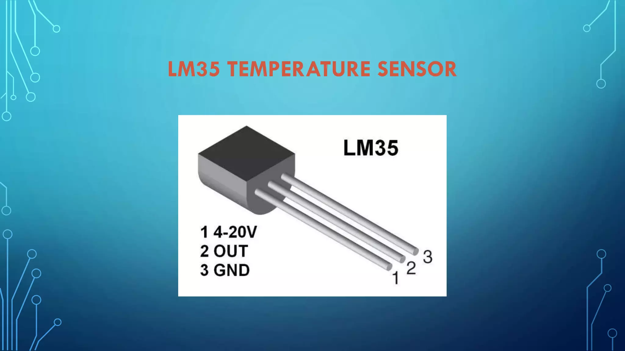
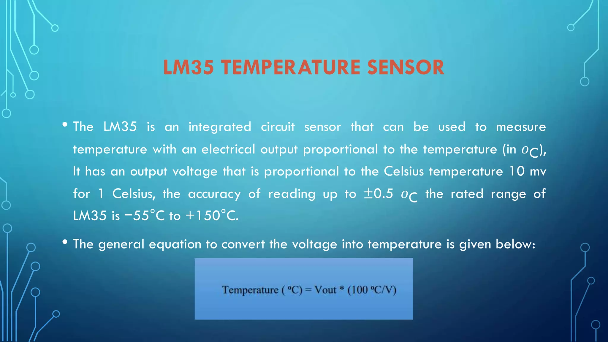
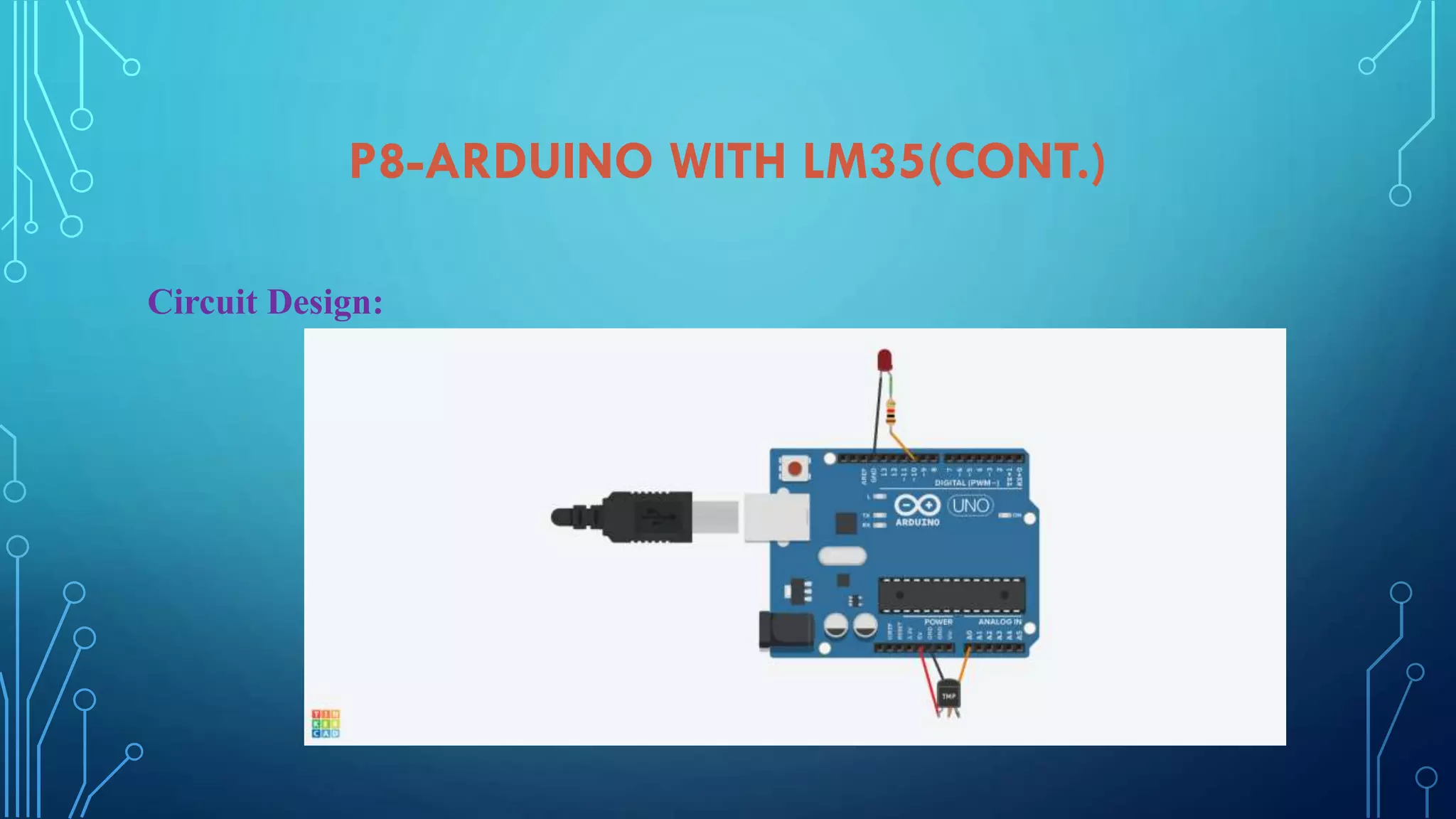
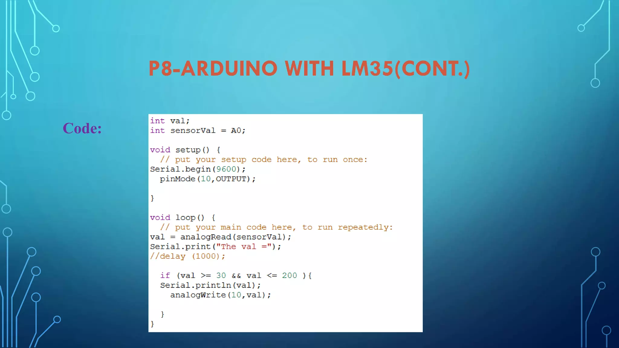
Detailed setup and coding for LM35 temperature sensor to measure temperature and its circuit design.
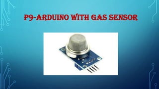
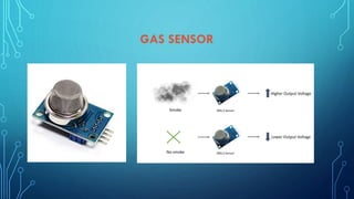
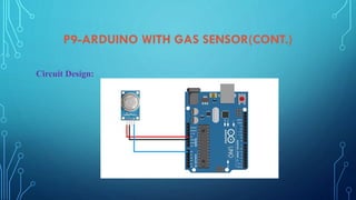
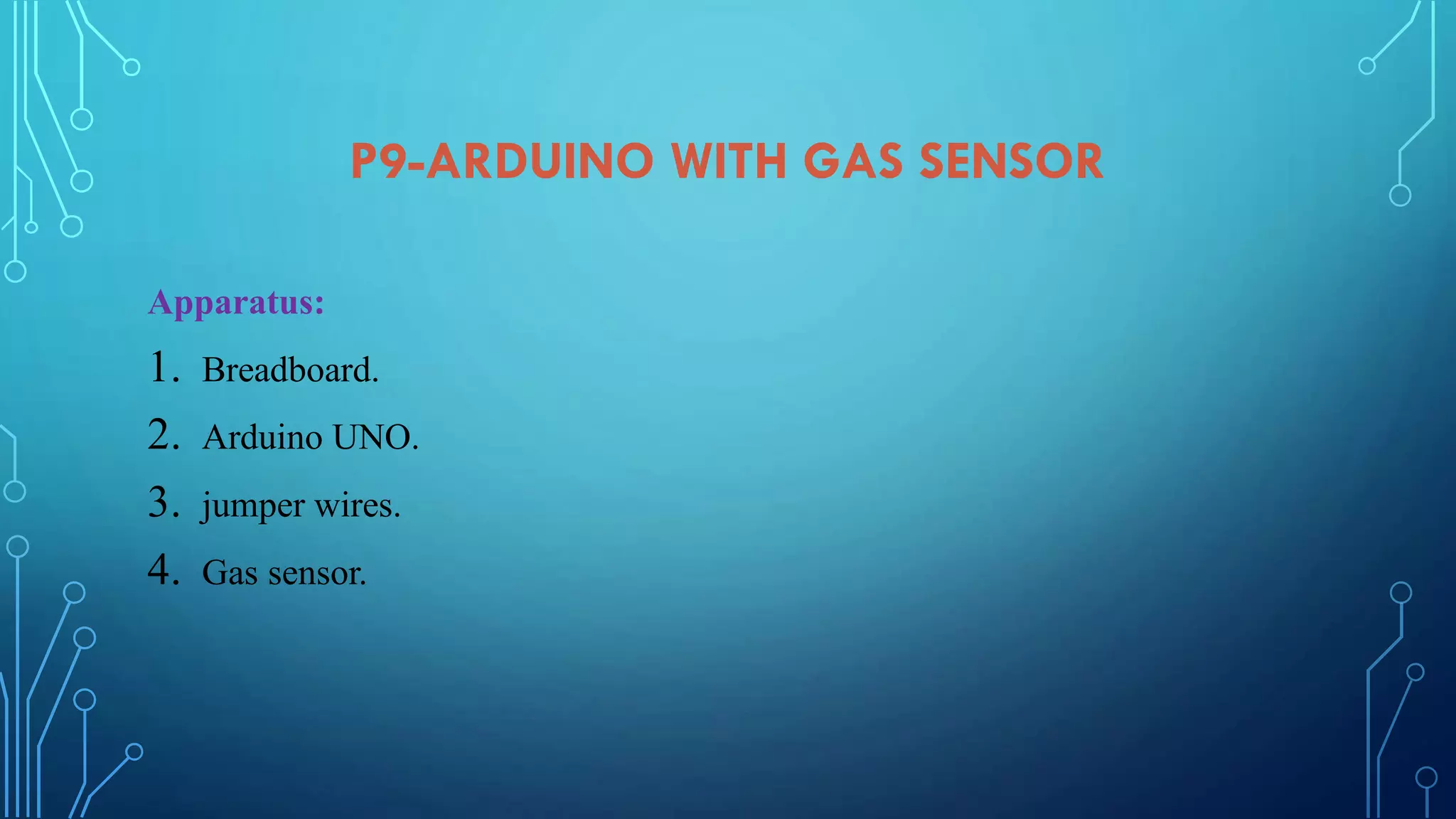
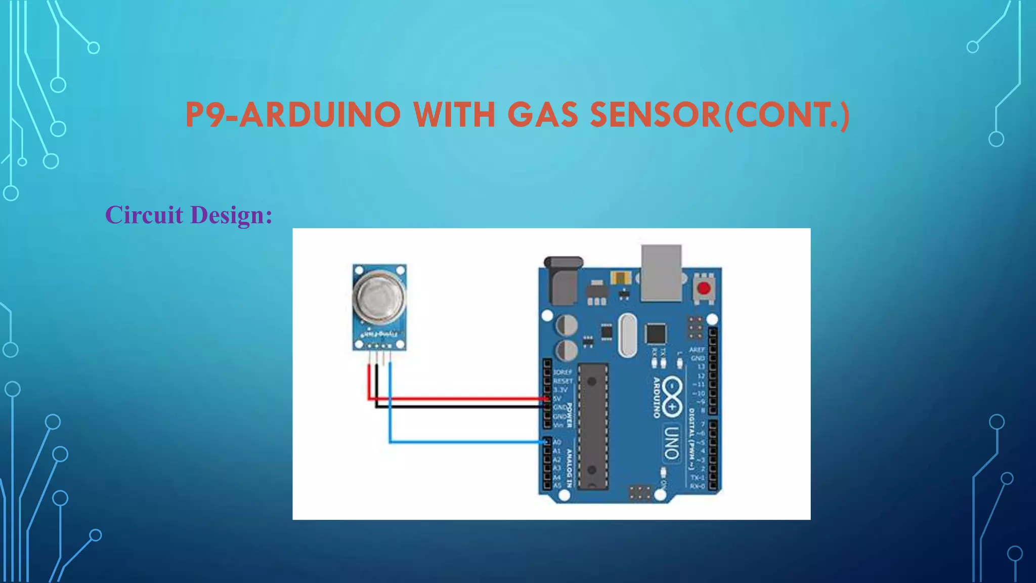
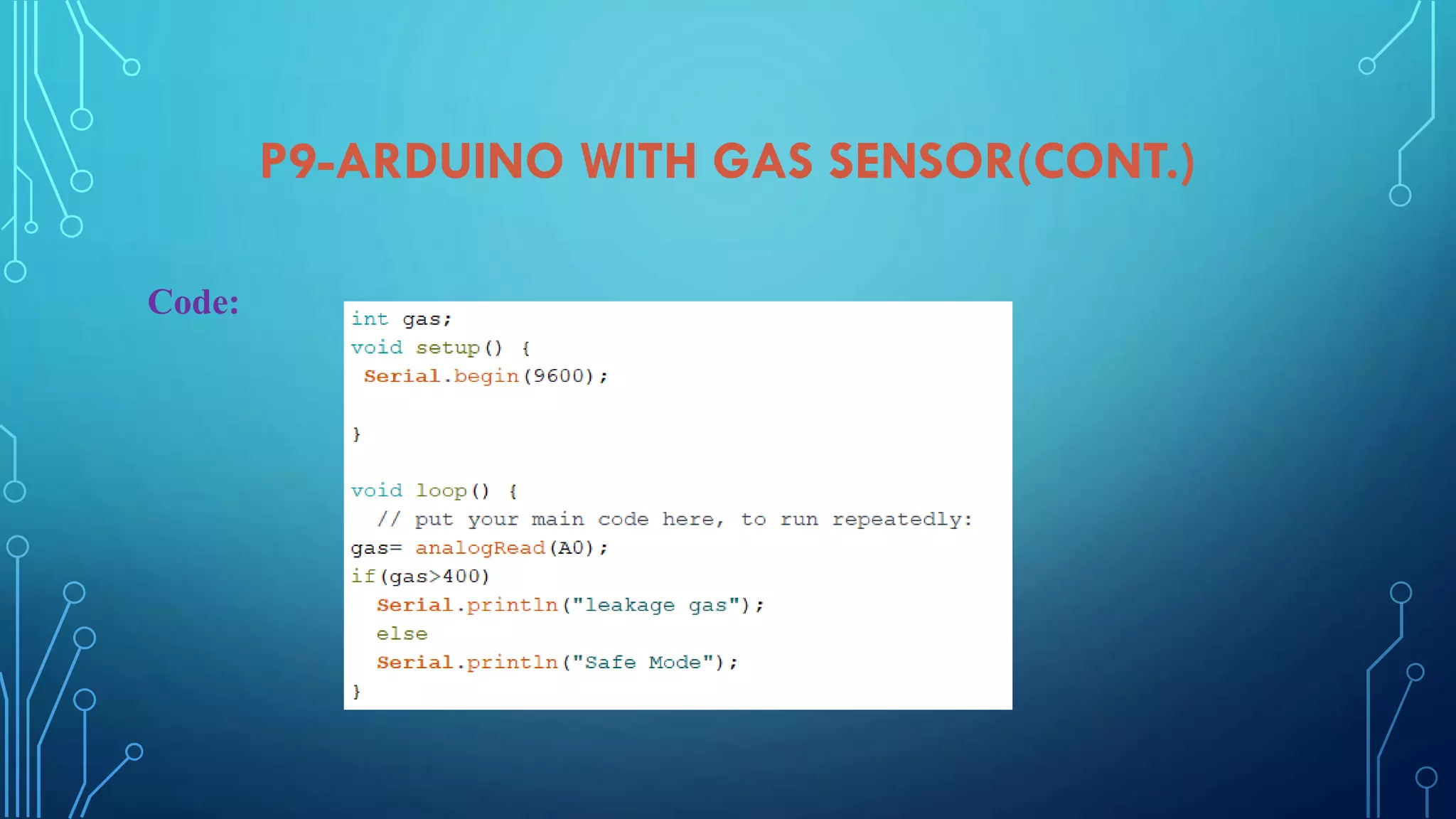
Gas sensor integration with Arduino, including apparatus, circuit design, and coding for monitoring gas.
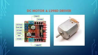
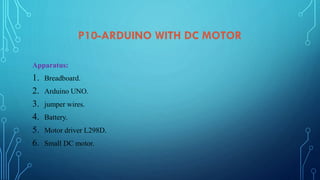
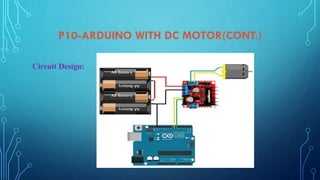
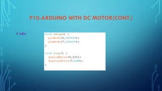
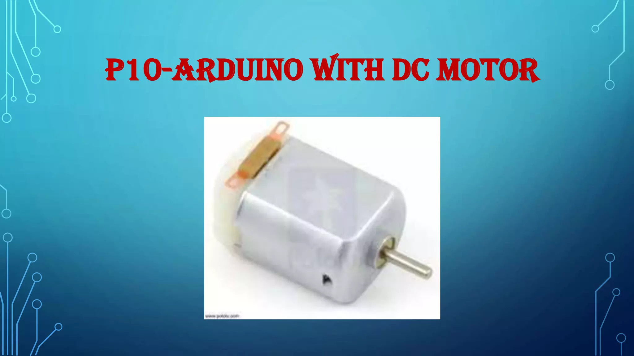
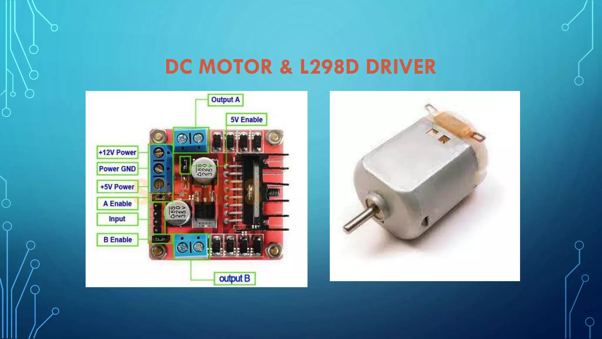
Implementing a DC motor with Arduino using a motor driver, including circuit and programming instructions.
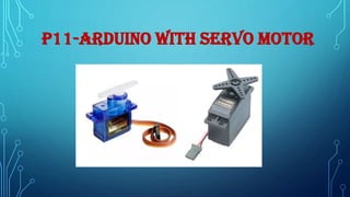
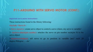
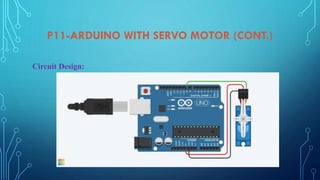
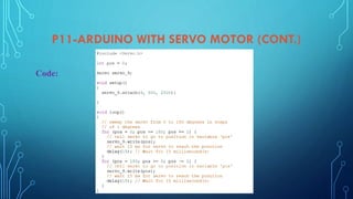
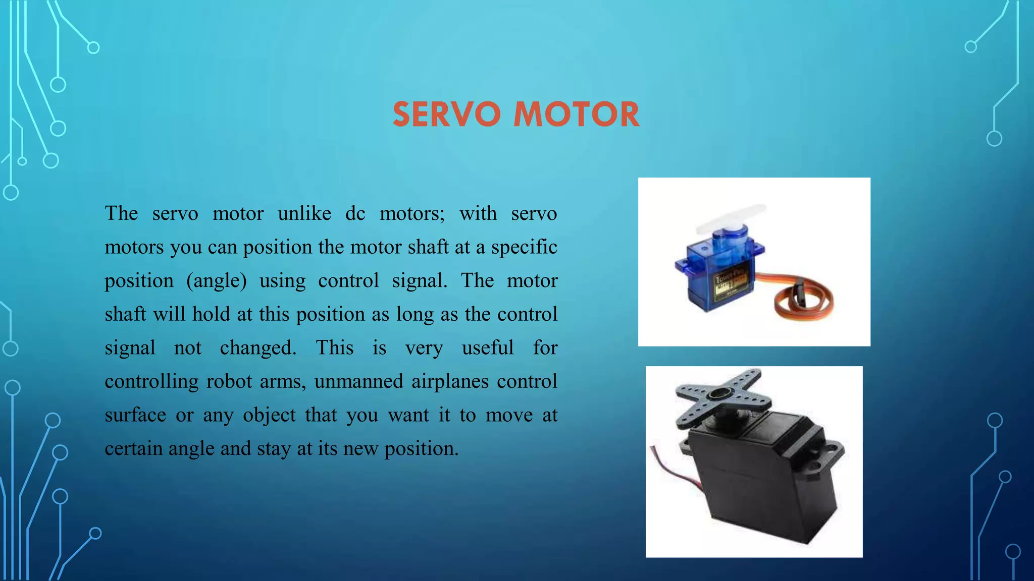
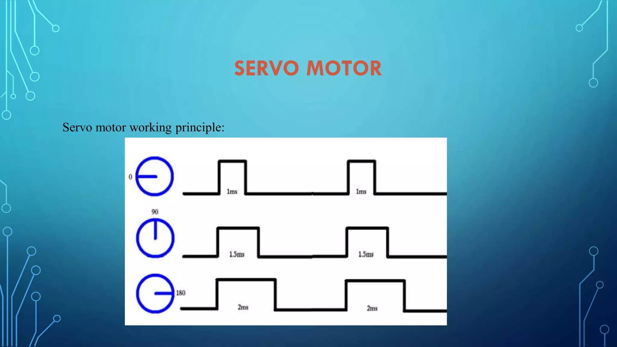
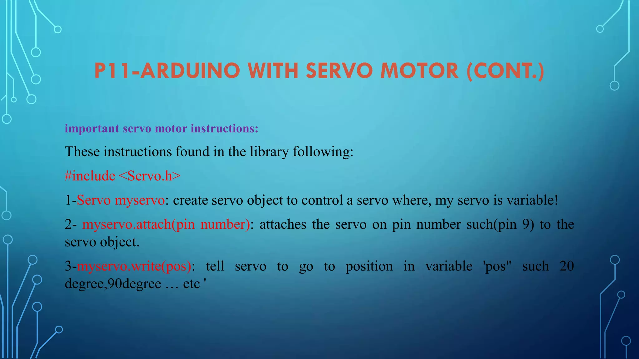
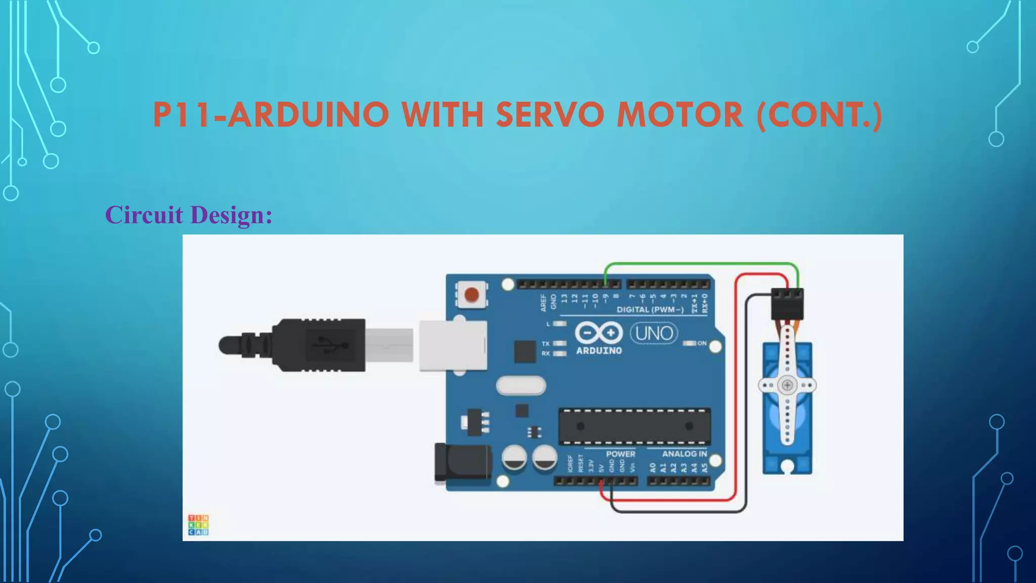
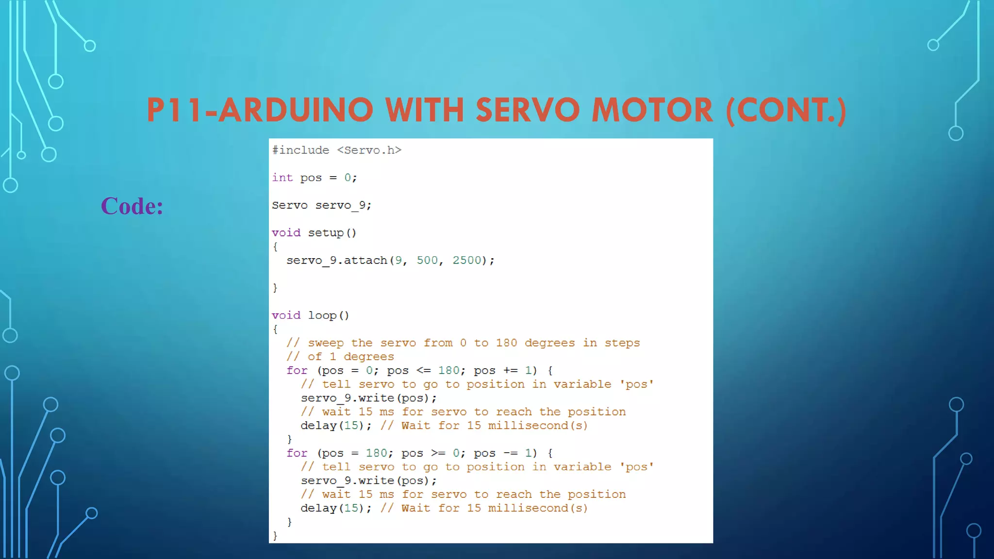
Setup and coding for servo motor control using Arduino, including functioning and circuit design.
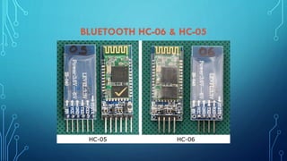
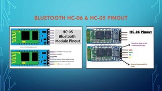
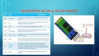
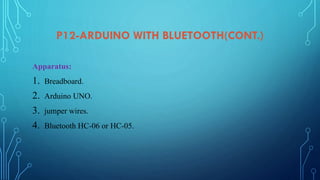
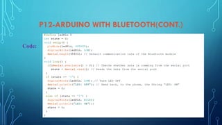
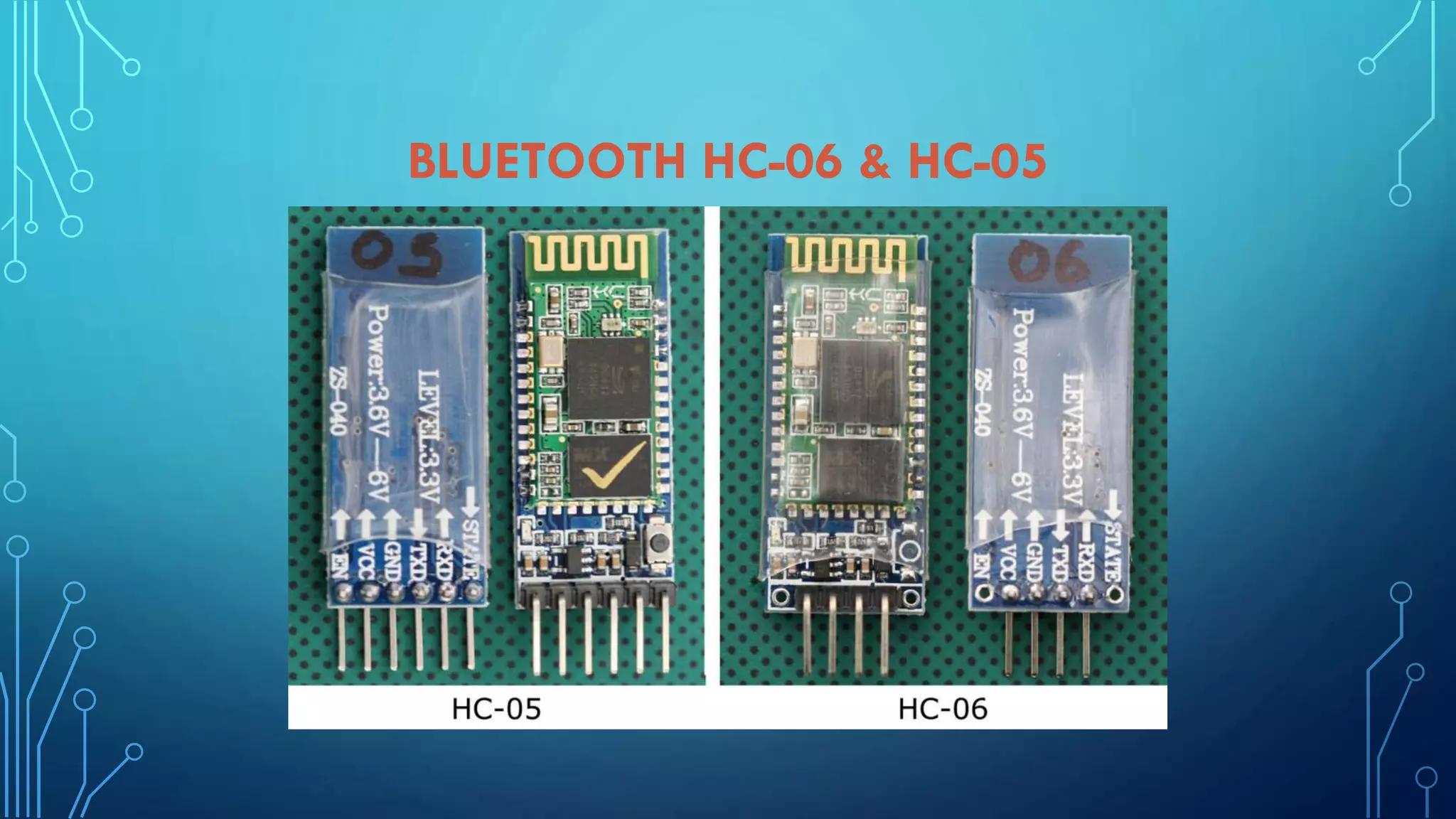
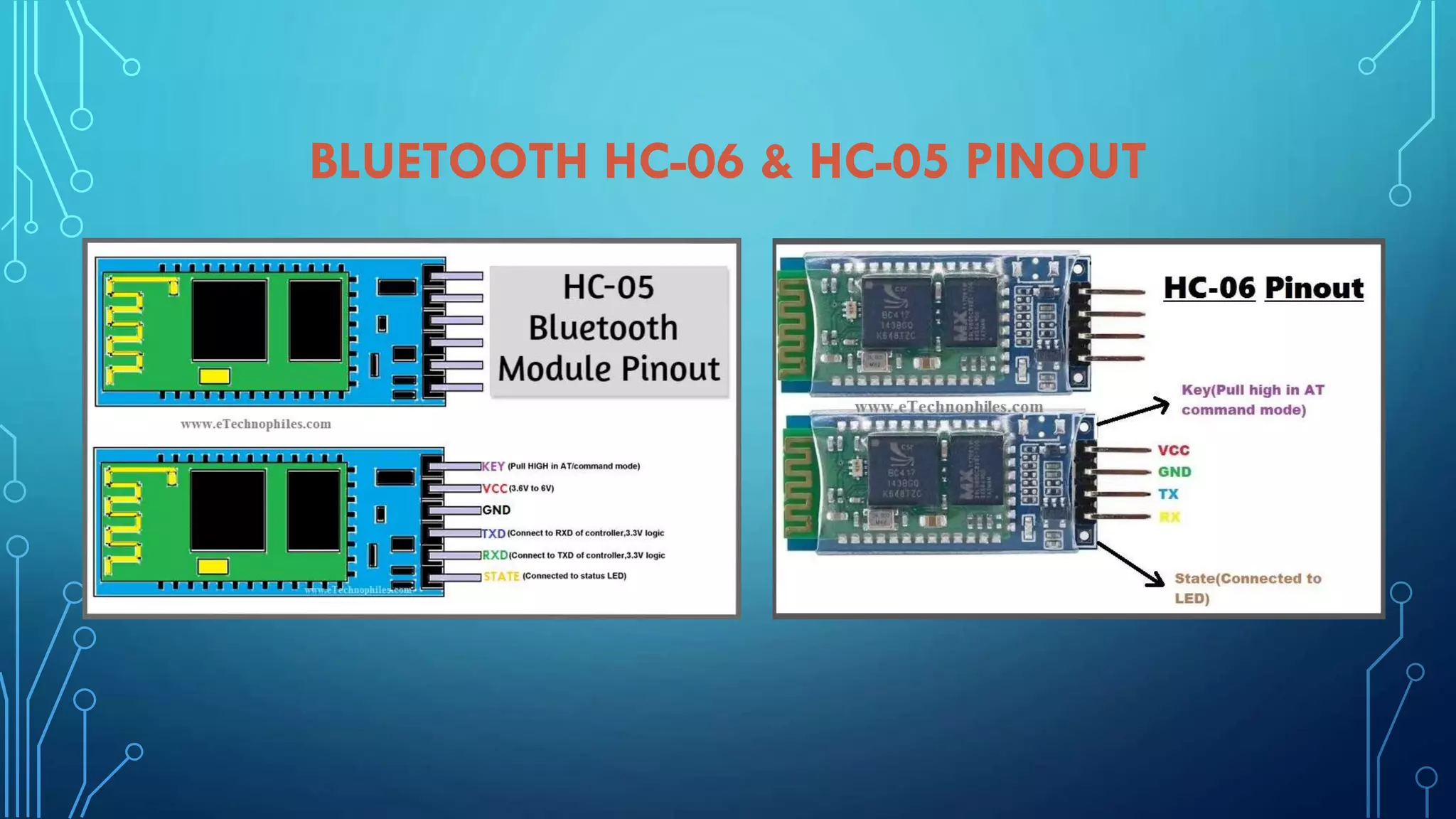
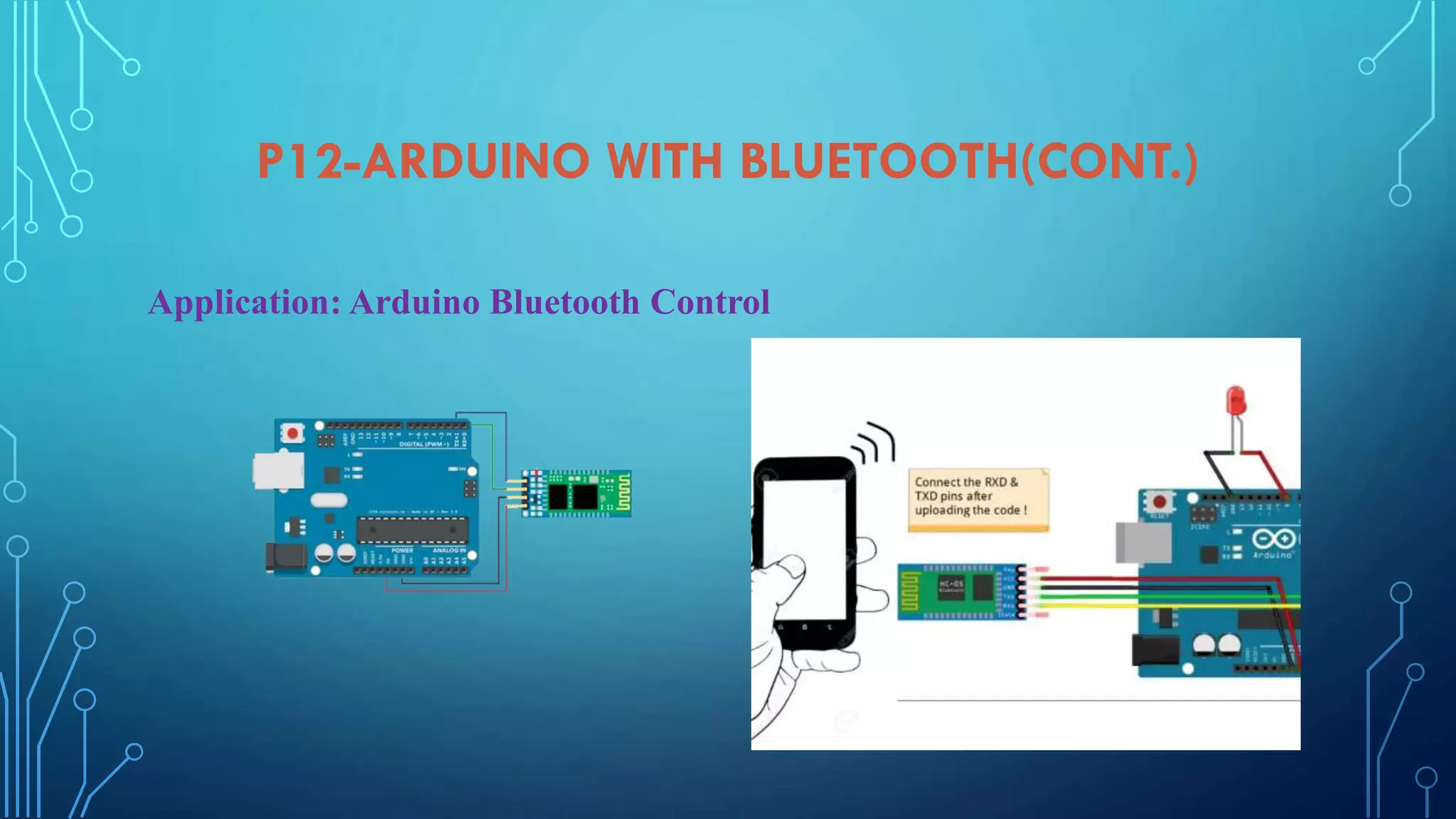
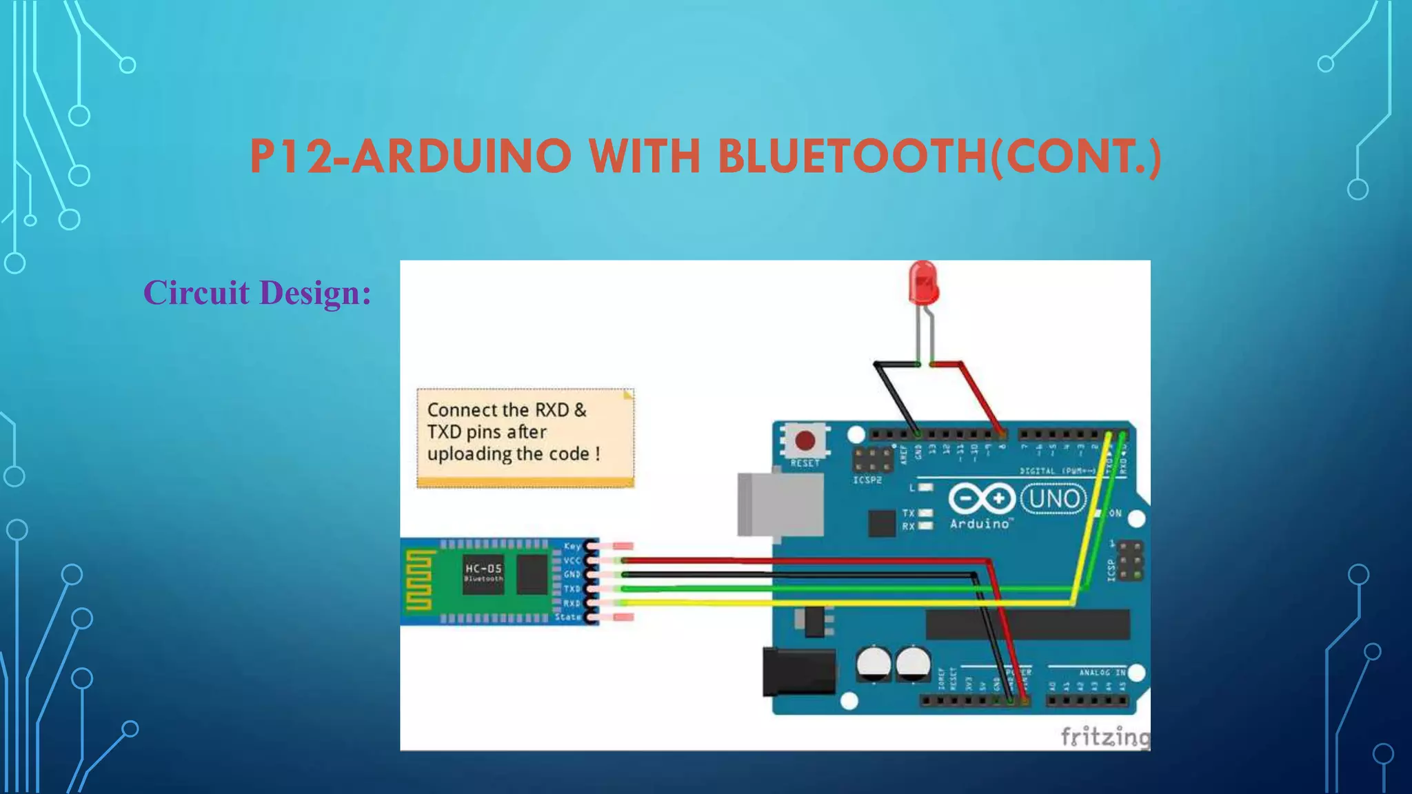
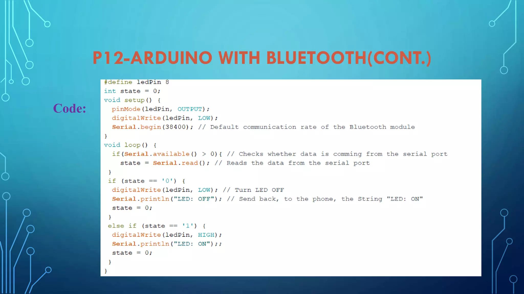
Working with Bluetooth HC-06/HC-05 module, including usage, AT command mode, and circuit design.
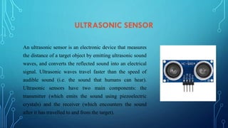
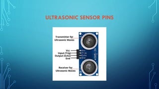
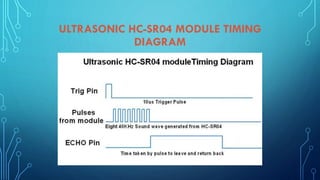
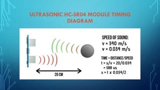
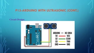
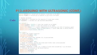
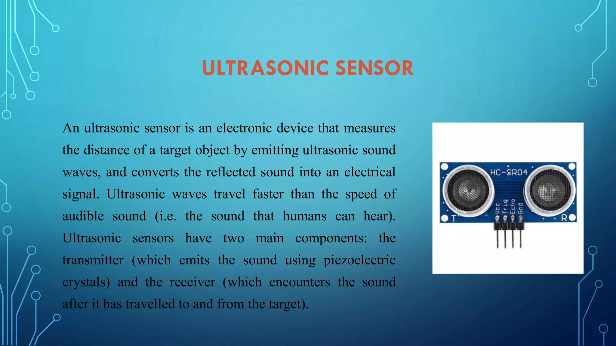
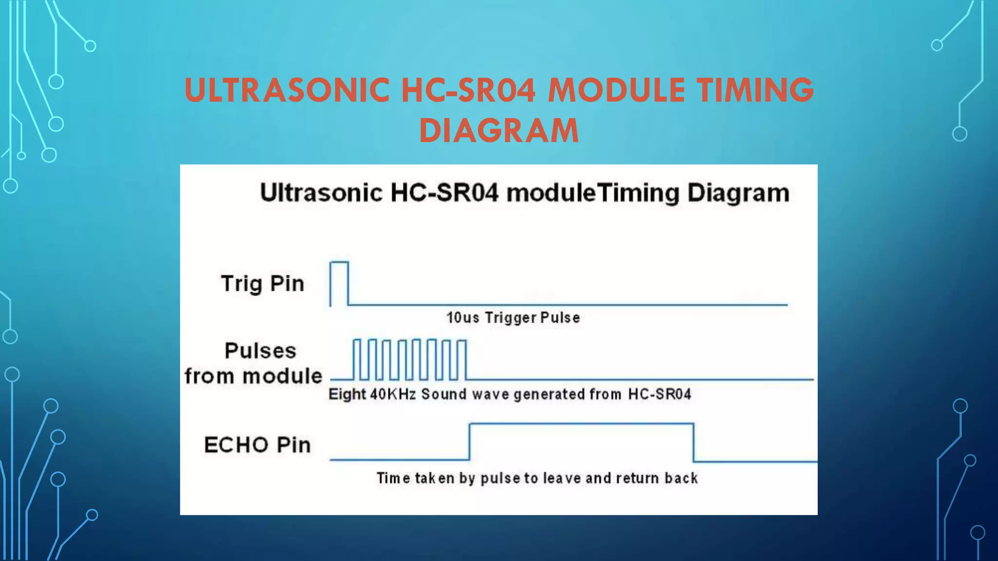
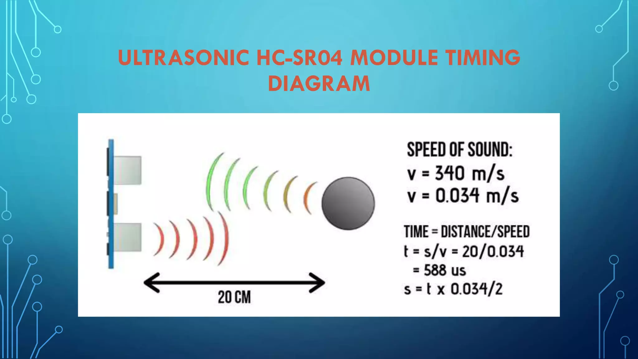
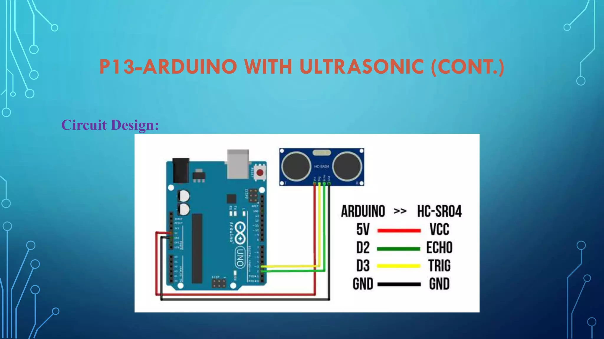
Overview of ultrasonic sensor functioning, circuit design, and coding for distance measurement.
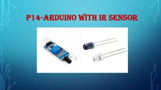
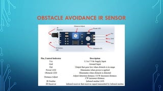
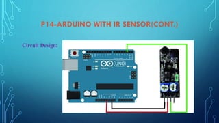
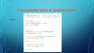
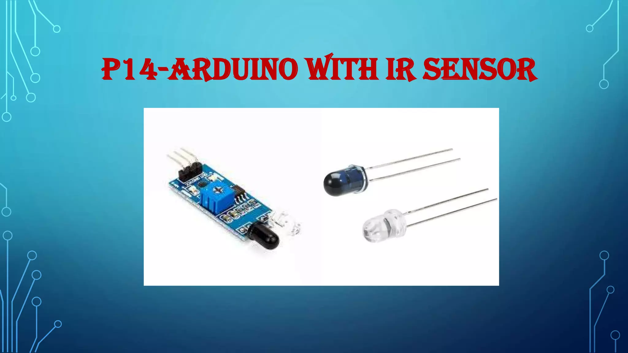
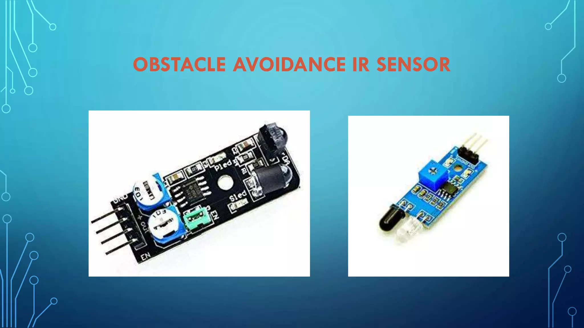
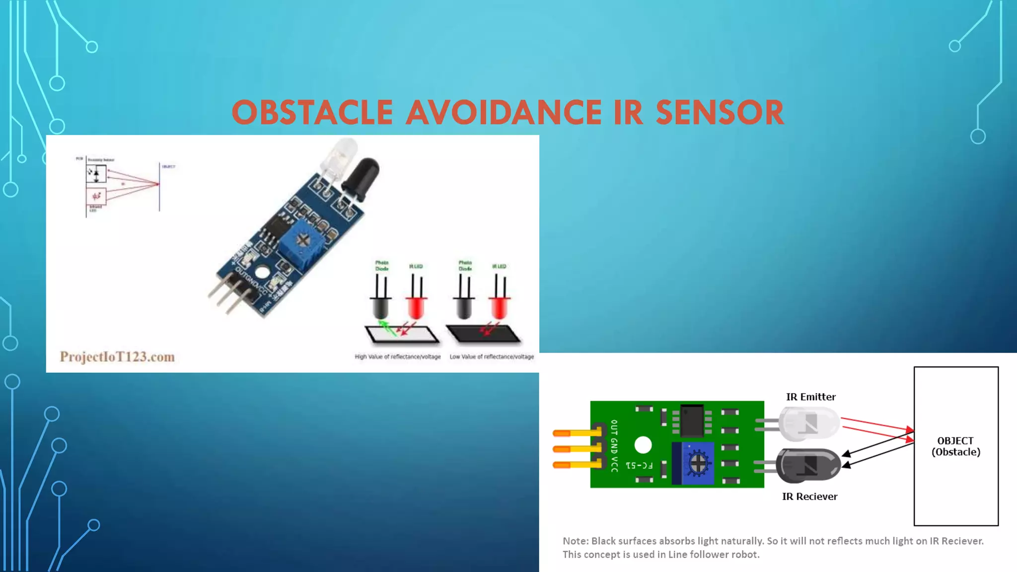
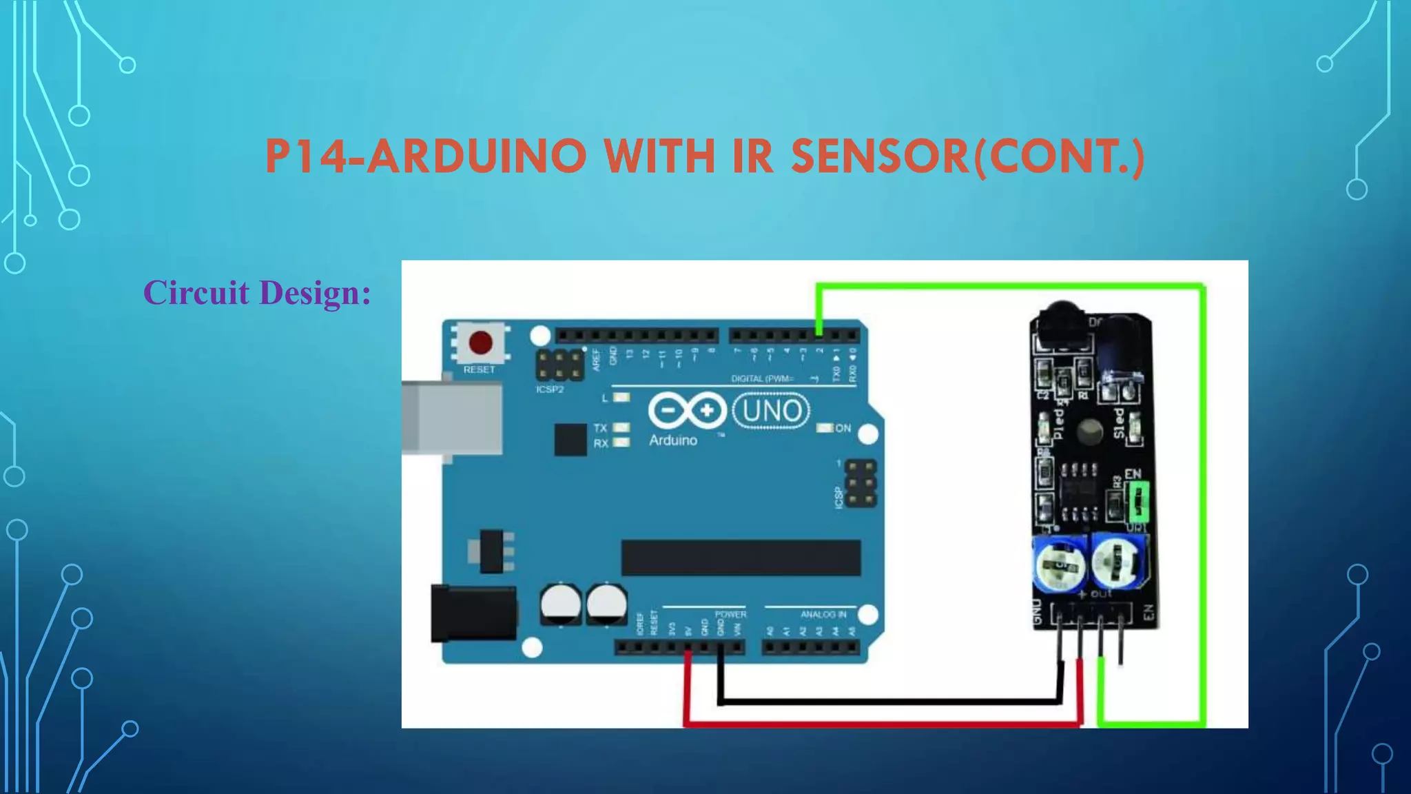
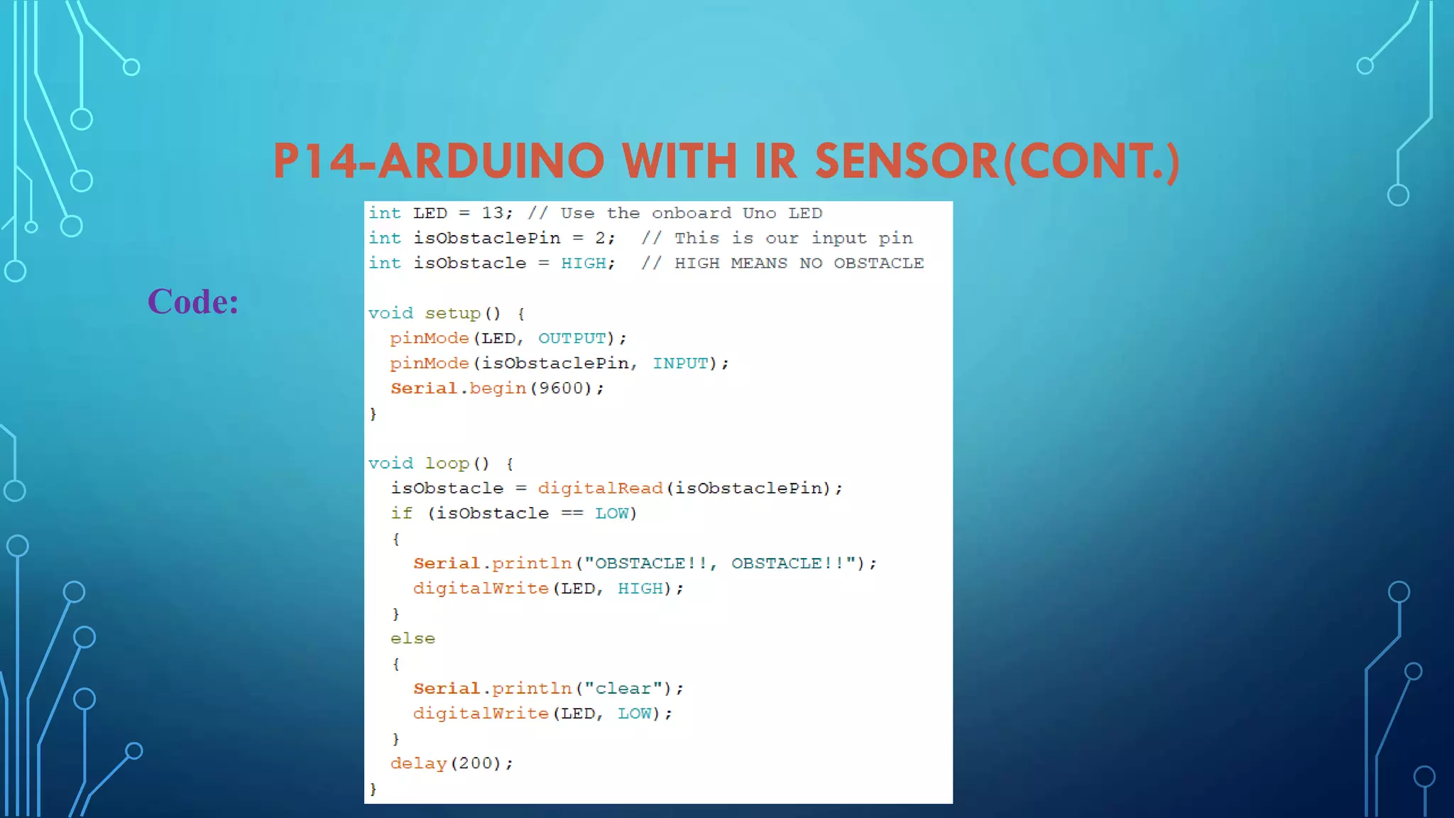
Details on using IR sensor for obstacle avoidance, including apparatus, circuit design, and coding.
Thank you note, contact details and links to author's professional profiles and resources.


![UiPath Automation Suite Installation (Hands-On) [2/3]](https://cdn.slidesharecdn.com/ss_thumbnails/automationsuitecommunitysession2-251015095633-a6d862f1-thumbnail.jpg?width=600ounds&width=560&fit=bounds)

