Downloaded 170 times


This project displays the current time and temperature using an Arduino board, LM35 temperature sensor, and DS1307 RTC module. The LM35 and DS1307 are connected to analog pins on the Arduino, which uses its onboard ADC to read the analog voltage values and display the converted time and temperature readings on an LCD screen. The key components required are the Arduino, sensors, LCD, and supporting electronics. The document provides details on how each component functions and how they interconnect and cooperate to continuously display the time and surrounding temperature.
Introduction to a project displaying time and temperature using Arduino, LM-35, and RTC DS-1307.
List of components needed for the project: Arduino board, sensors (temperature & time), LCD, breadboard, and miscellaneous items.
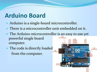
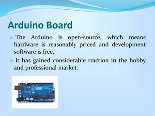
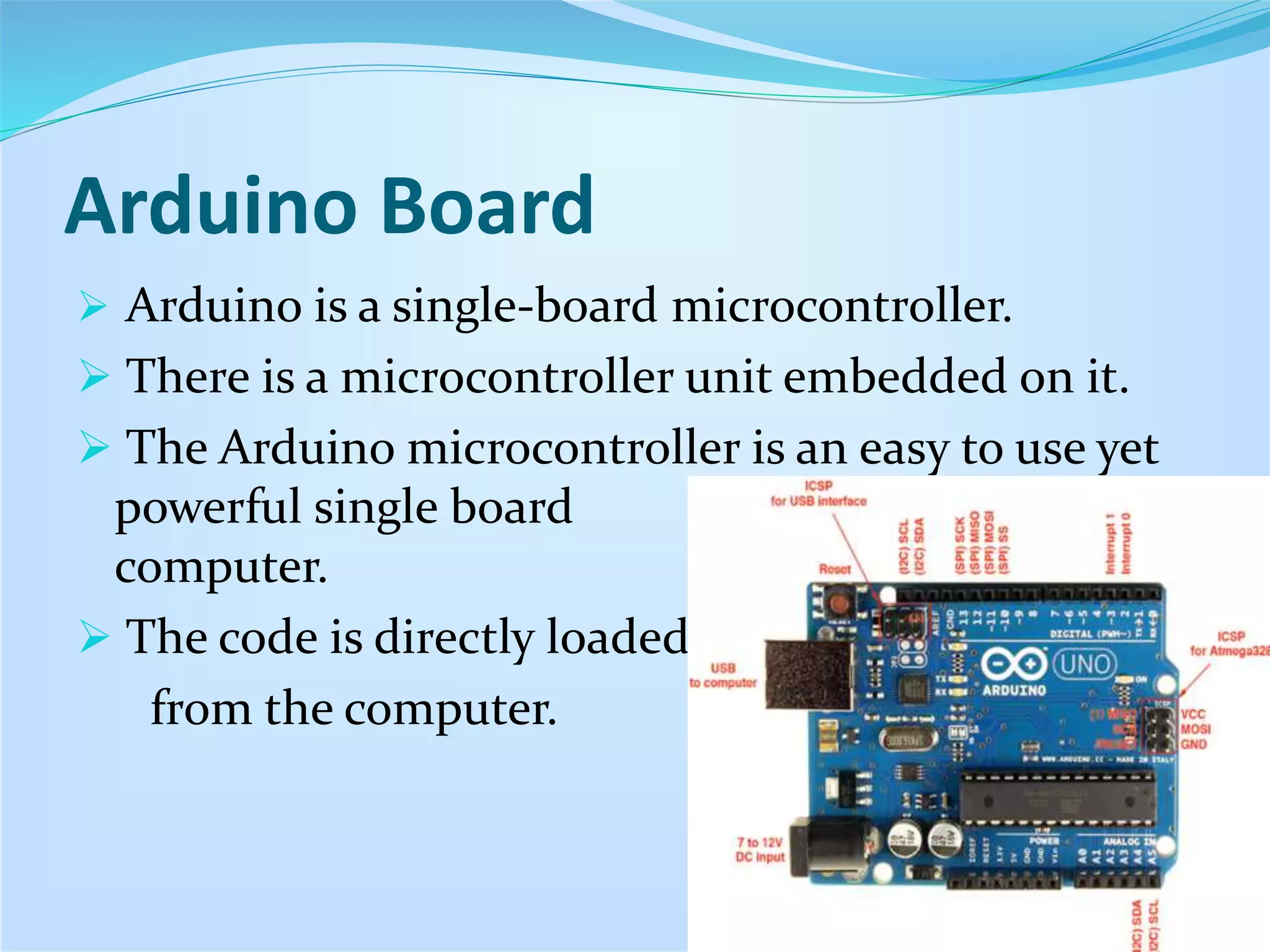
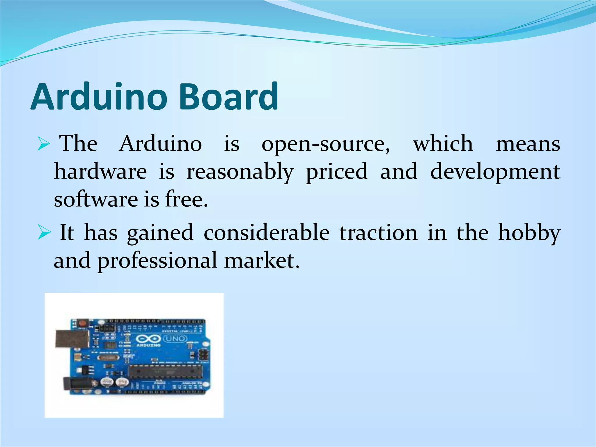
Description of Arduino as a single-board microcontroller, its ease of use, affordability, and popularity in various markets.
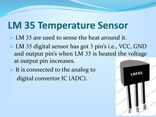
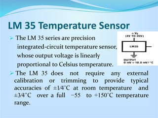
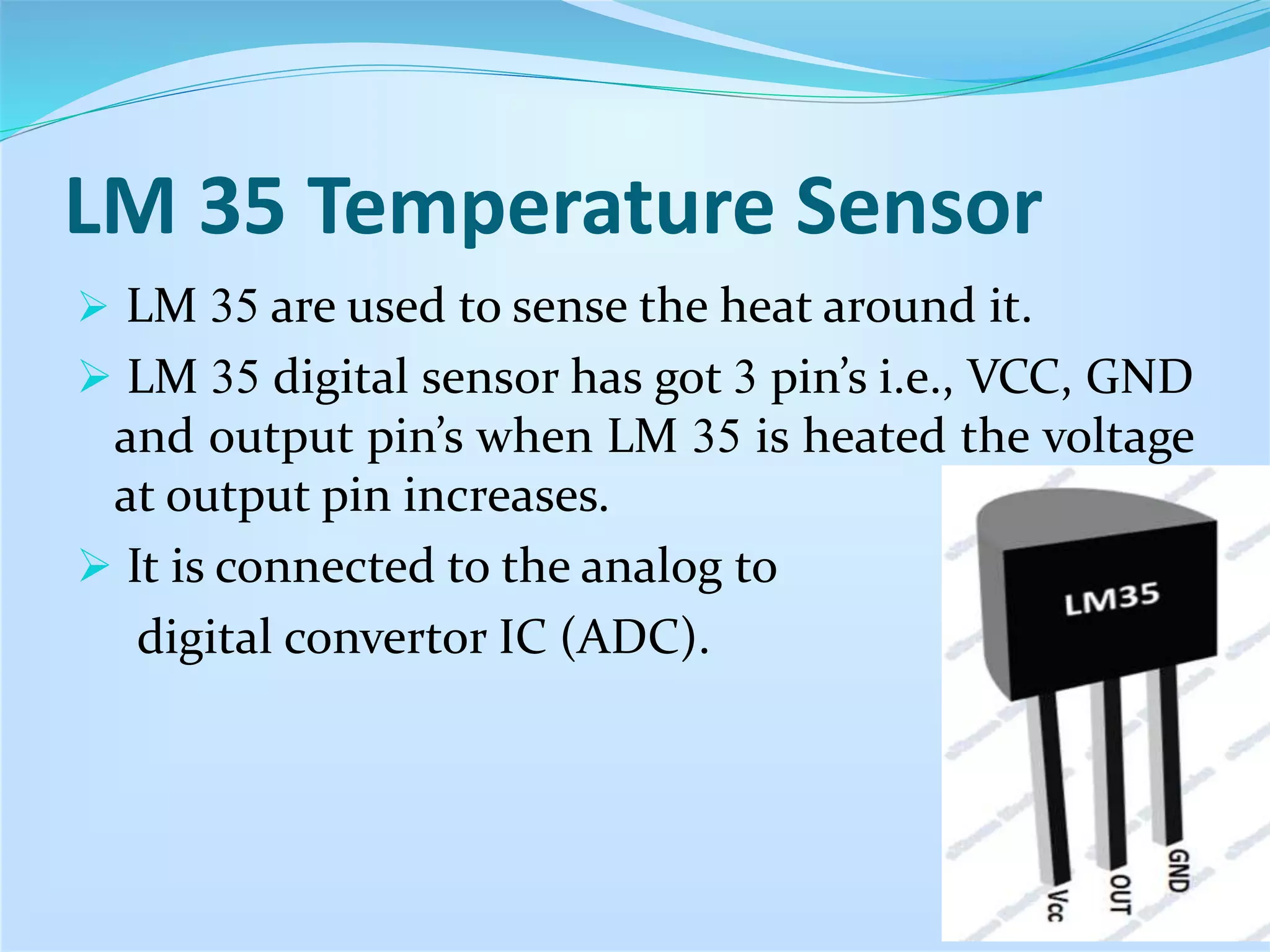
Details about LM 35 sensors: their operation, pin configuration, temperature sensitivity and accuracy without external calibration.
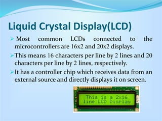
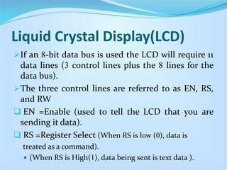
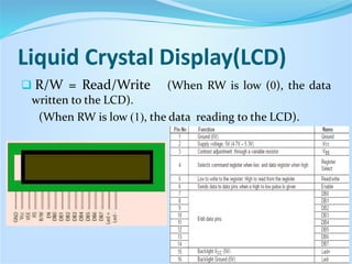
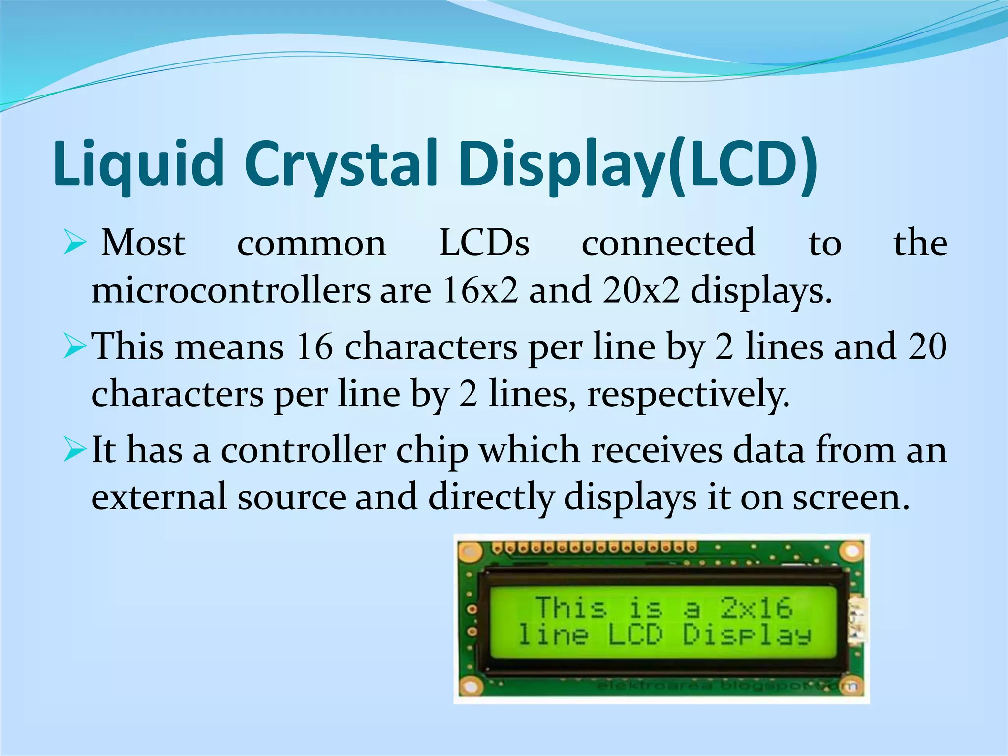
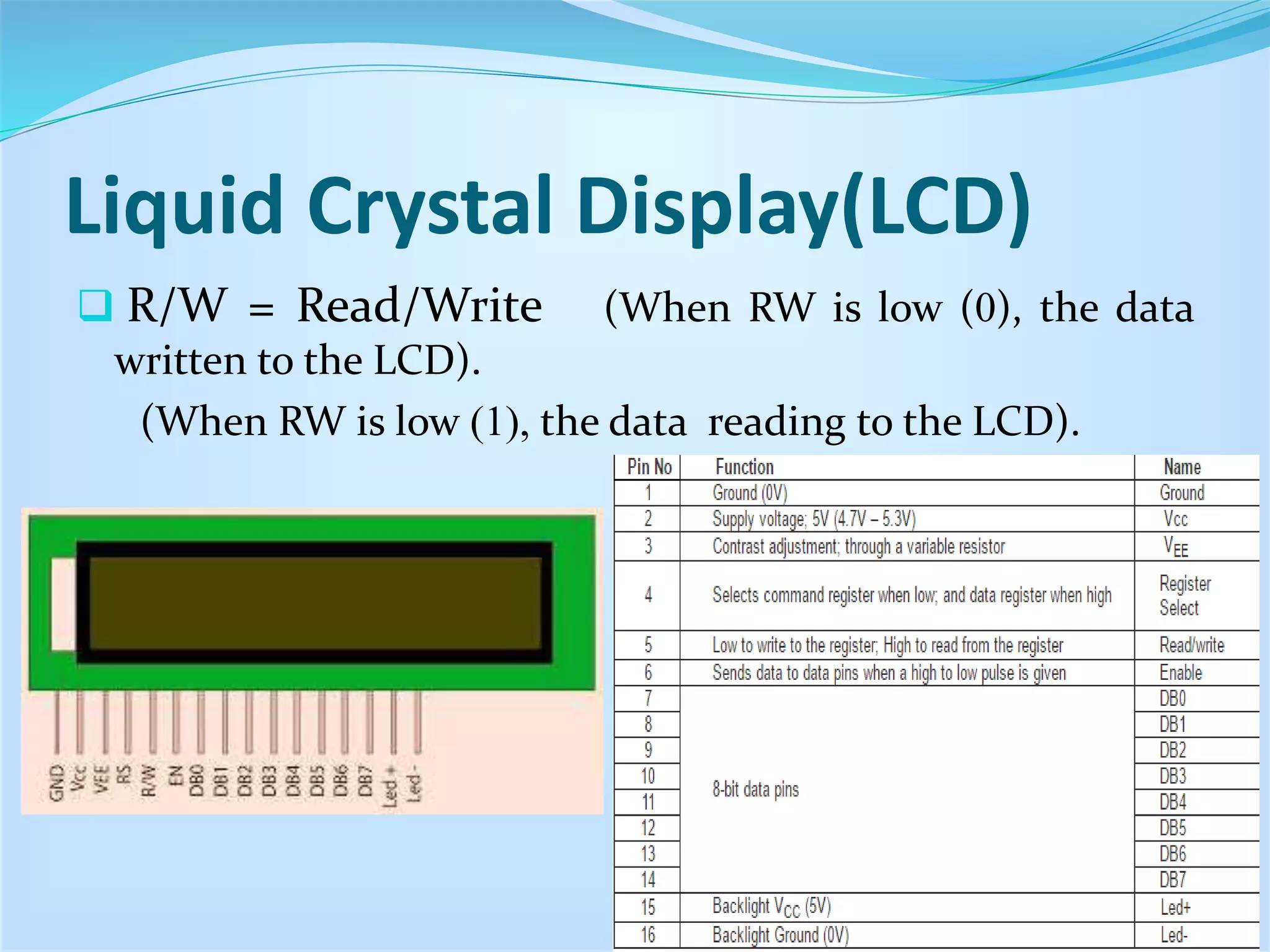
Overview of common LCD types (16x2, 20x2) and explanation of data bus and control lines essential for operation.
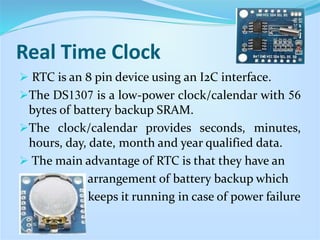
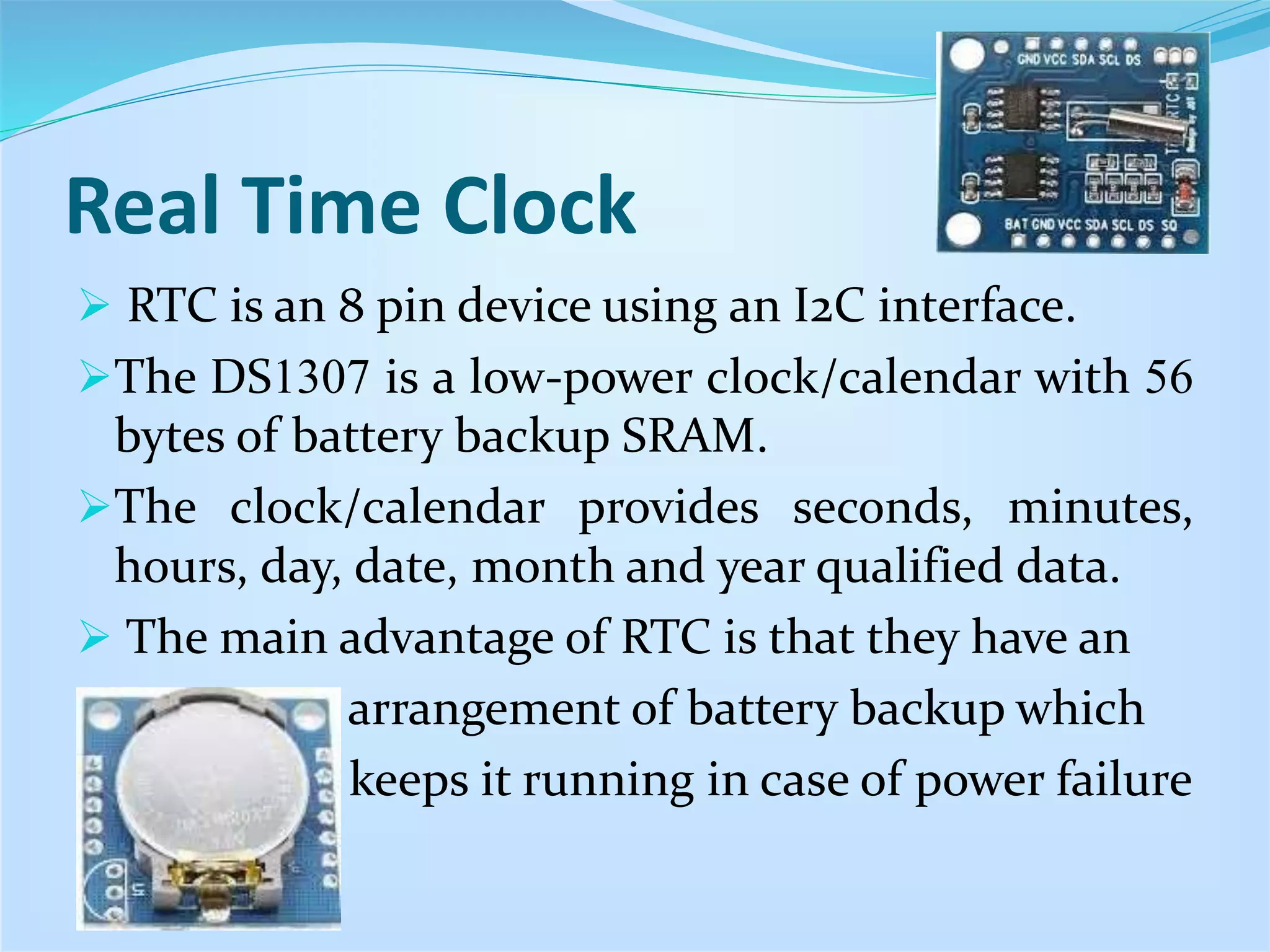
Introduction and features of RTC DS1307, including its low power consumption and battery backup to maintain time.
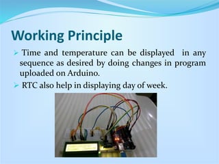
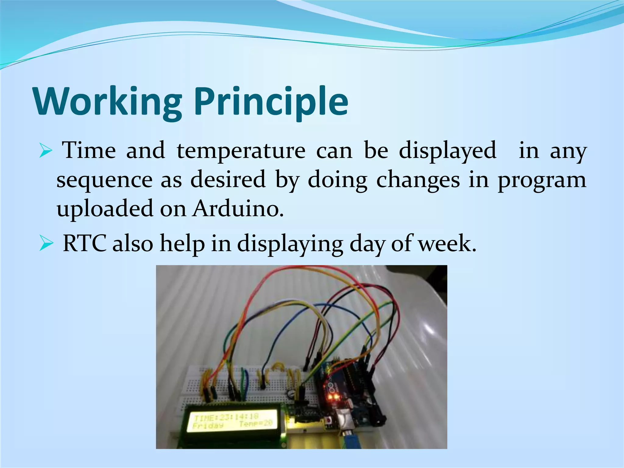
Explanation of the working principle of the setup using Arduino, LM-35, and RTC to output time and temperature on LCD.
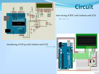
Diagram and explanation of interfacing between Arduino, RTC, LM 35, and the LCD.
References for the project provided, including acknowledgment of ECE teacher’s support.


