Downloaded 150 times

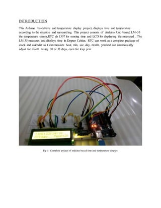


This project report describes an Arduino-based time and temperature display. The project uses an Arduino board interfaced with an LM35 temperature sensor to measure temperature and display it on an LCD. An RTC DS1307 module is also interfaced to measure the current time and display it along with the temperature on the LCD. The report provides details of the components used, circuit diagram, programming code and working of the project to continuously display current time and temperature.
Introduction of ECE project on Arduino-based time and temperature display and acknowledgments.
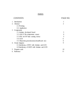
Project index detailing contents, figures, and visual representation related to the components.
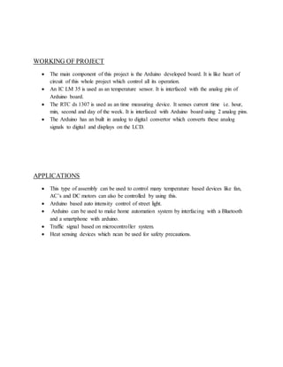
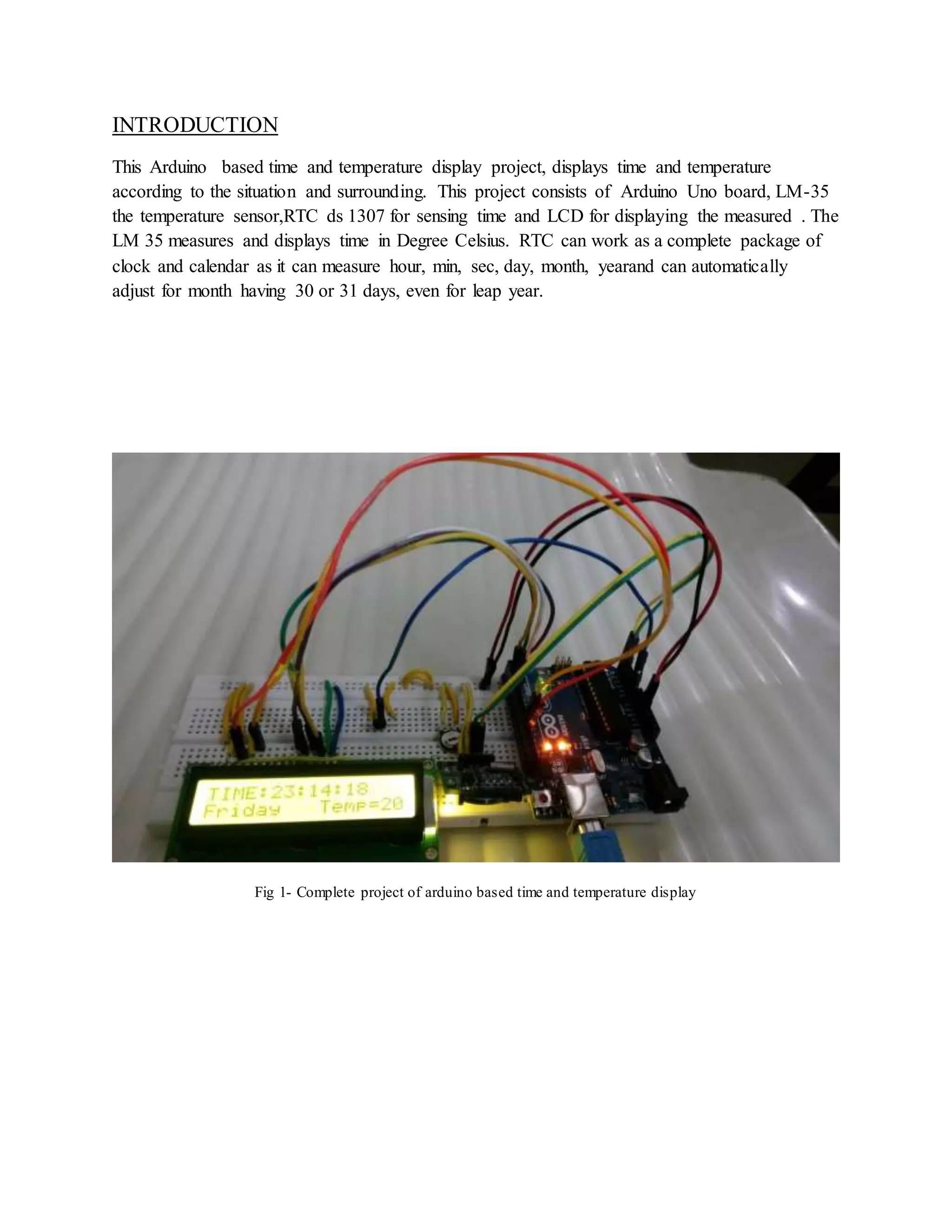
Overview of the project functionality, components, and applications including Arduino and sensors.
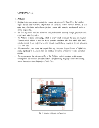
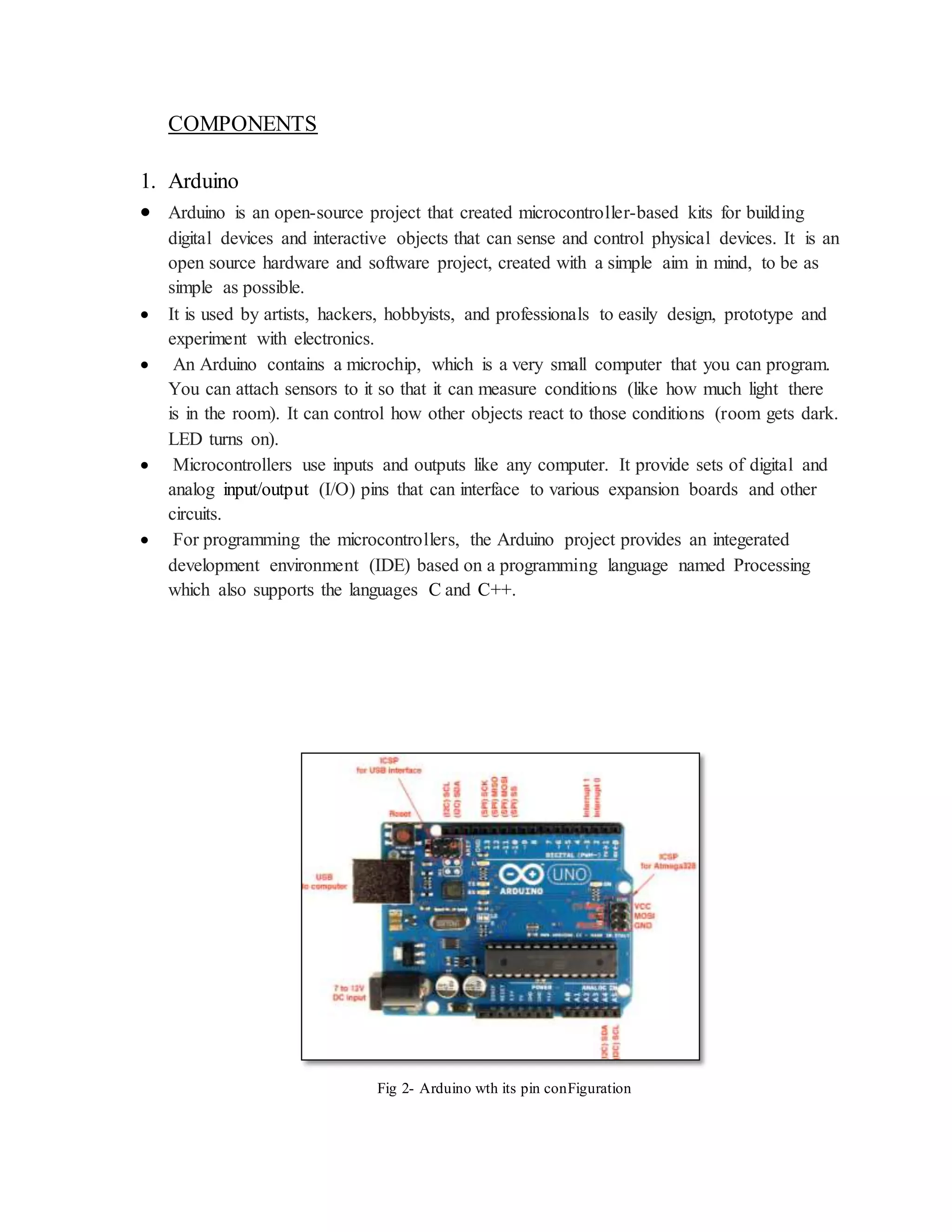
Details on Arduino as an open-source microcontroller used for various electronic applications.
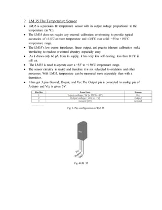
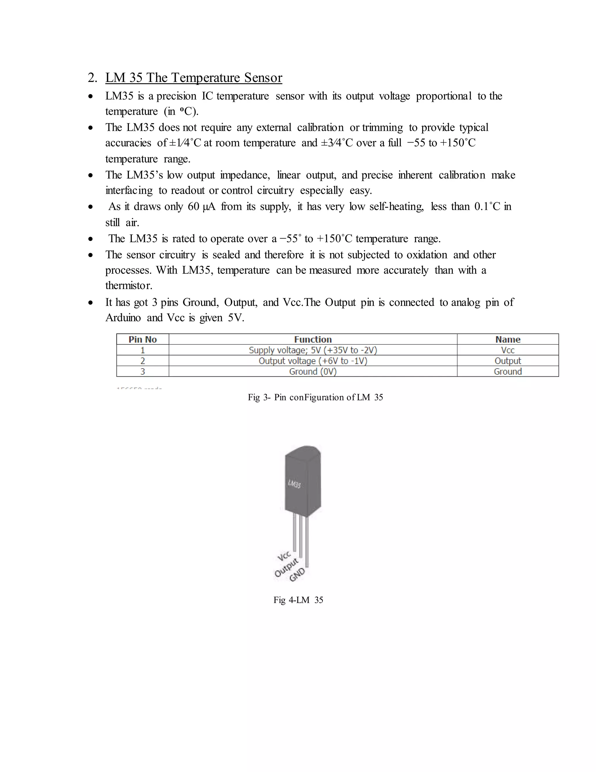
Description of LM35 sensor's specifications, accuracy, and use in measuring temperature.
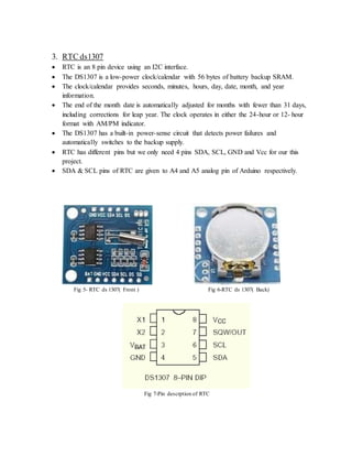
Information on RTC ds1307 functionality, powering, and interfacing with Arduino.
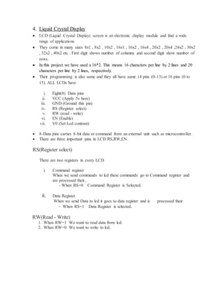
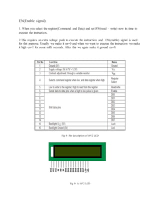
LCD details including types, pin functions, and usage in the project to display data.
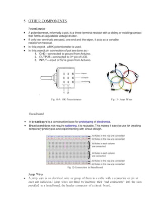
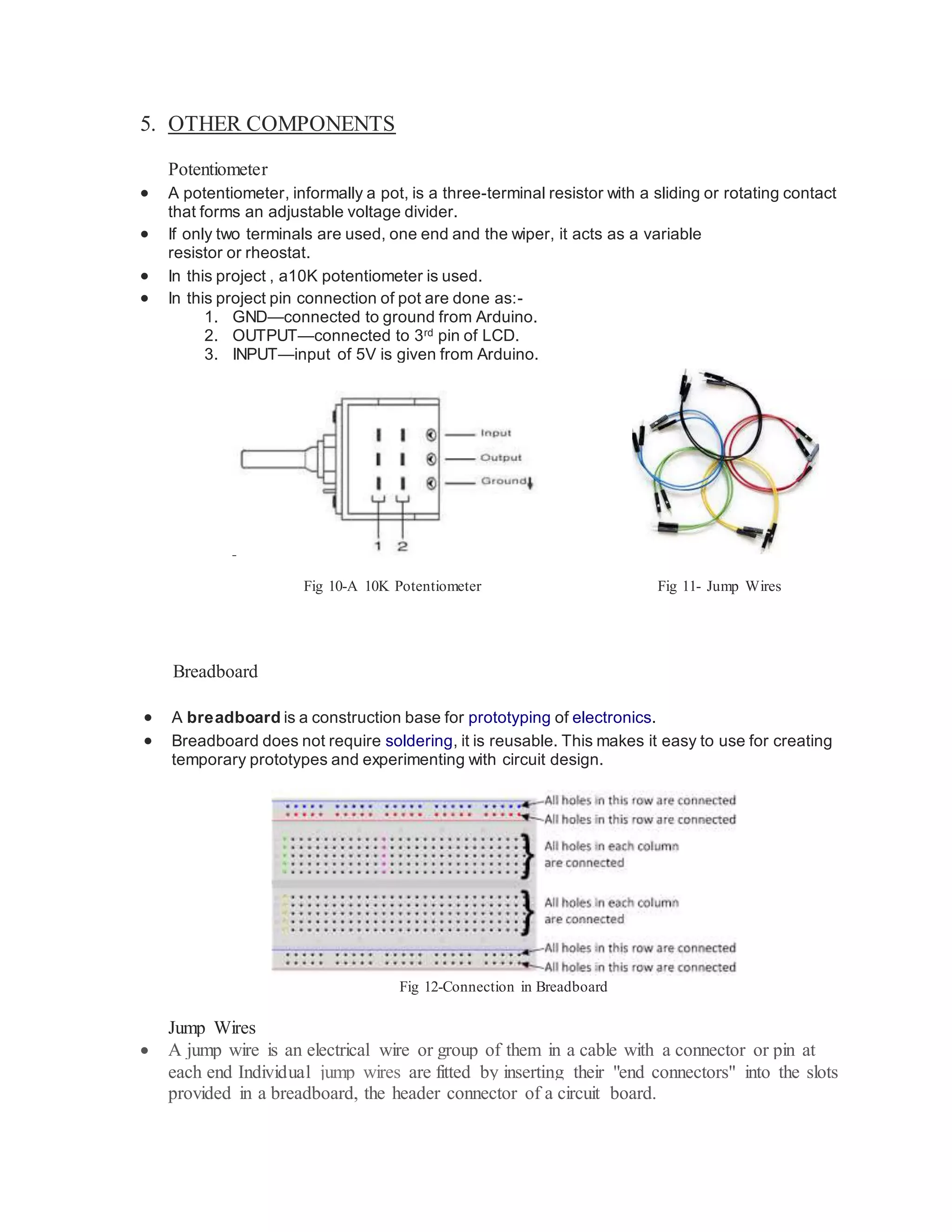
Explains the role of potentiometers, breadboards, and jump wires in the project.
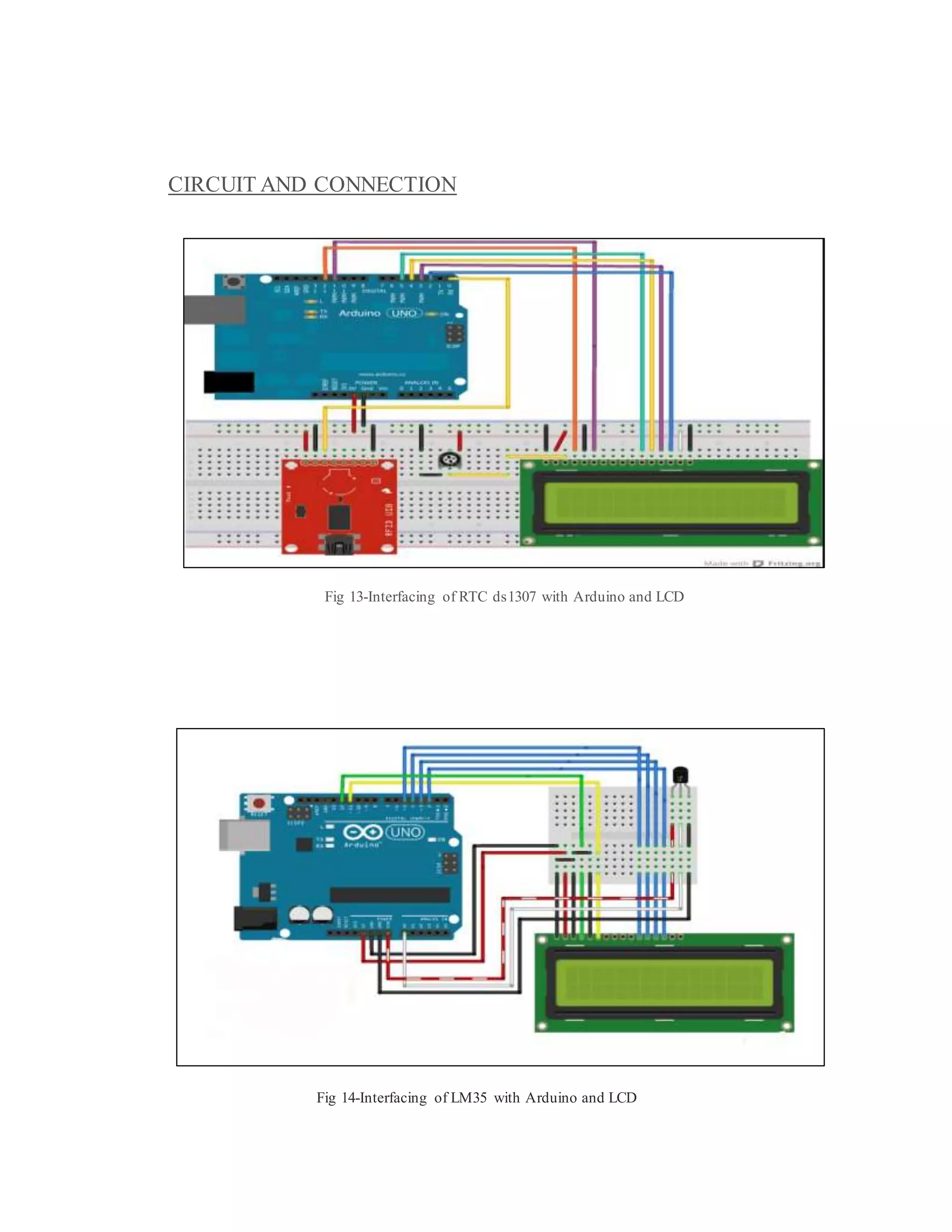
Visual representation of circuit connections between components such as the RTC and LM35.
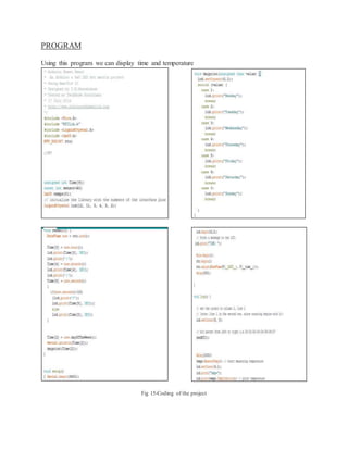
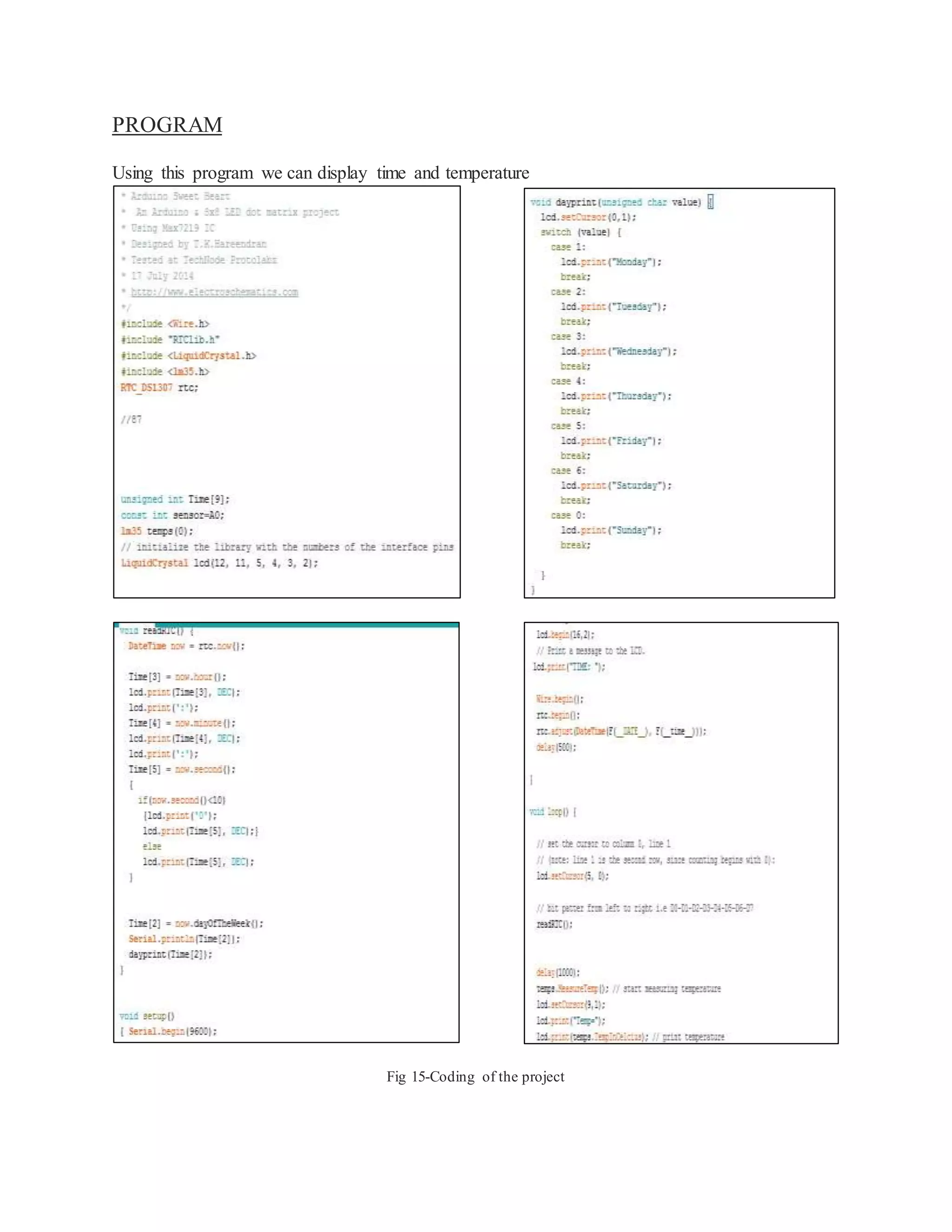
Overview of the program that enables functionality to display time and temperature.
Reflection on project execution and acknowledgments for resources and guidance provided.


![Advanced View Arduino Projects List - Use Arduino for Projects [04].pdf](https://cdn.slidesharecdn.com/ss_thumbnails/advancedviewarduinoprojectslist-usearduinoforprojects04-230111035056-673e6ac7-thumbnail.jpg?width=600ounds&width=560&fit=bounds)


