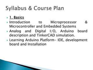
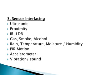
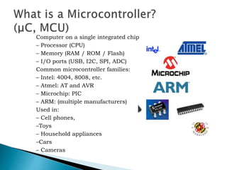
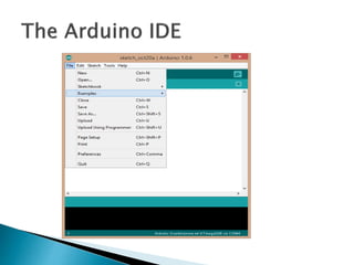
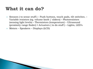
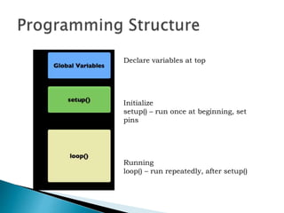
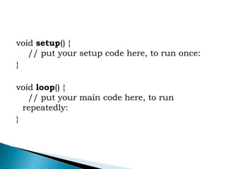
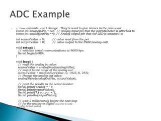
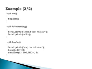
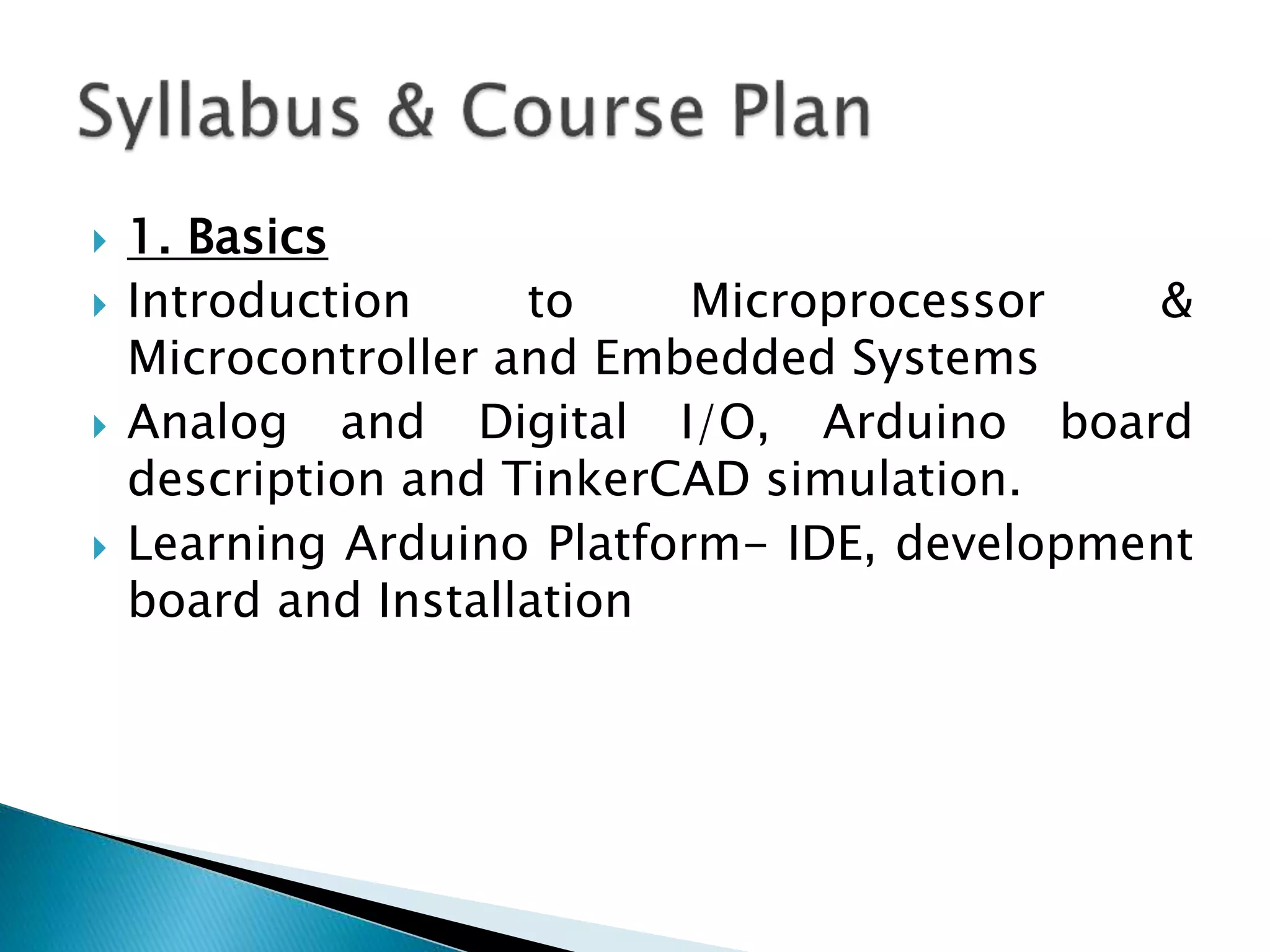
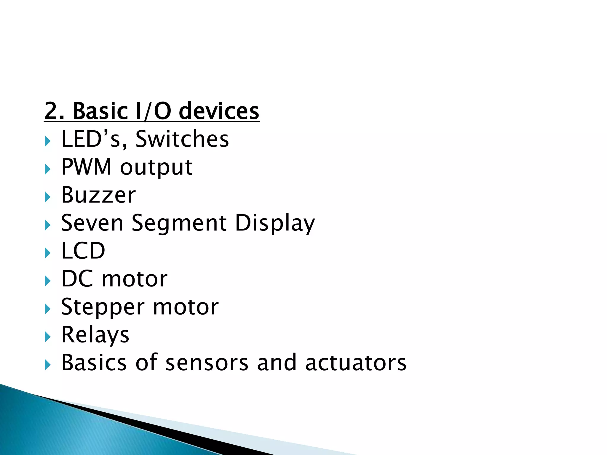
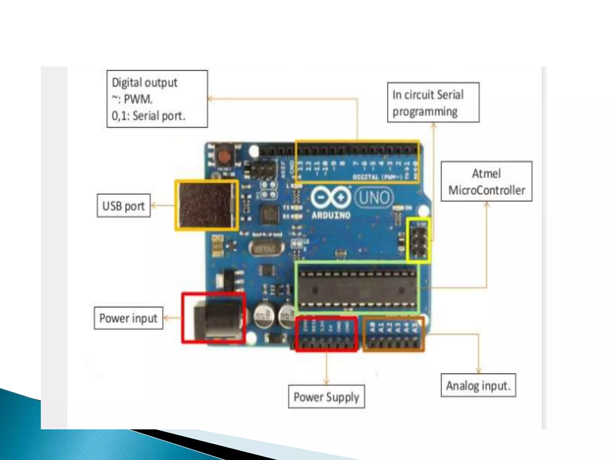
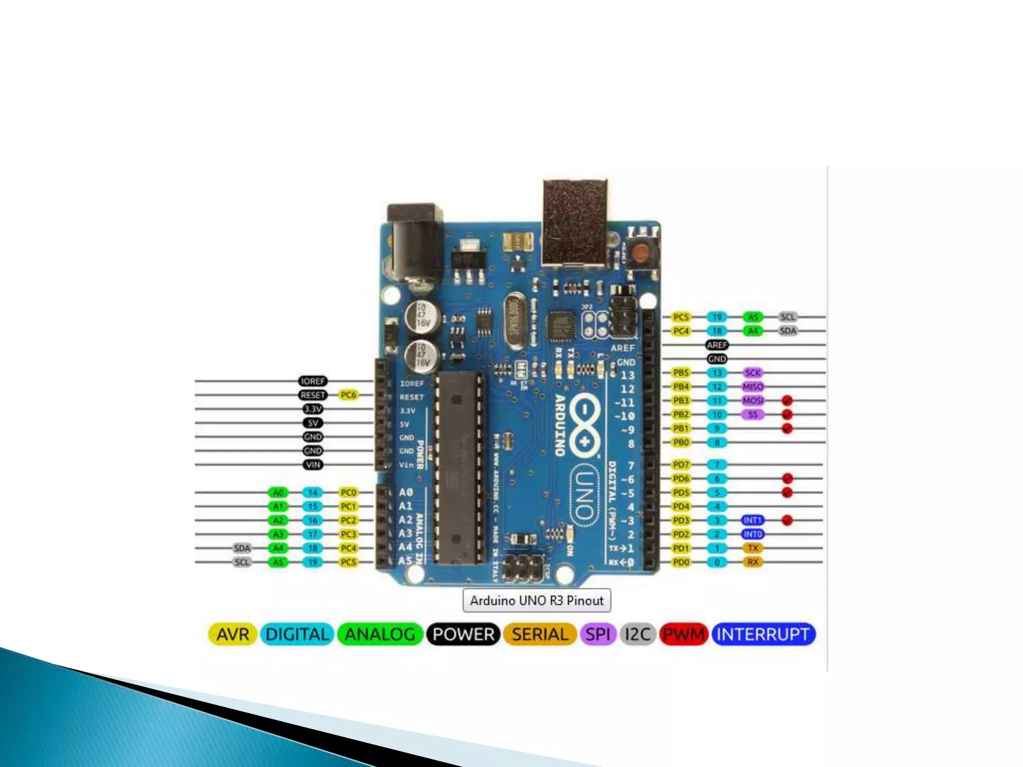
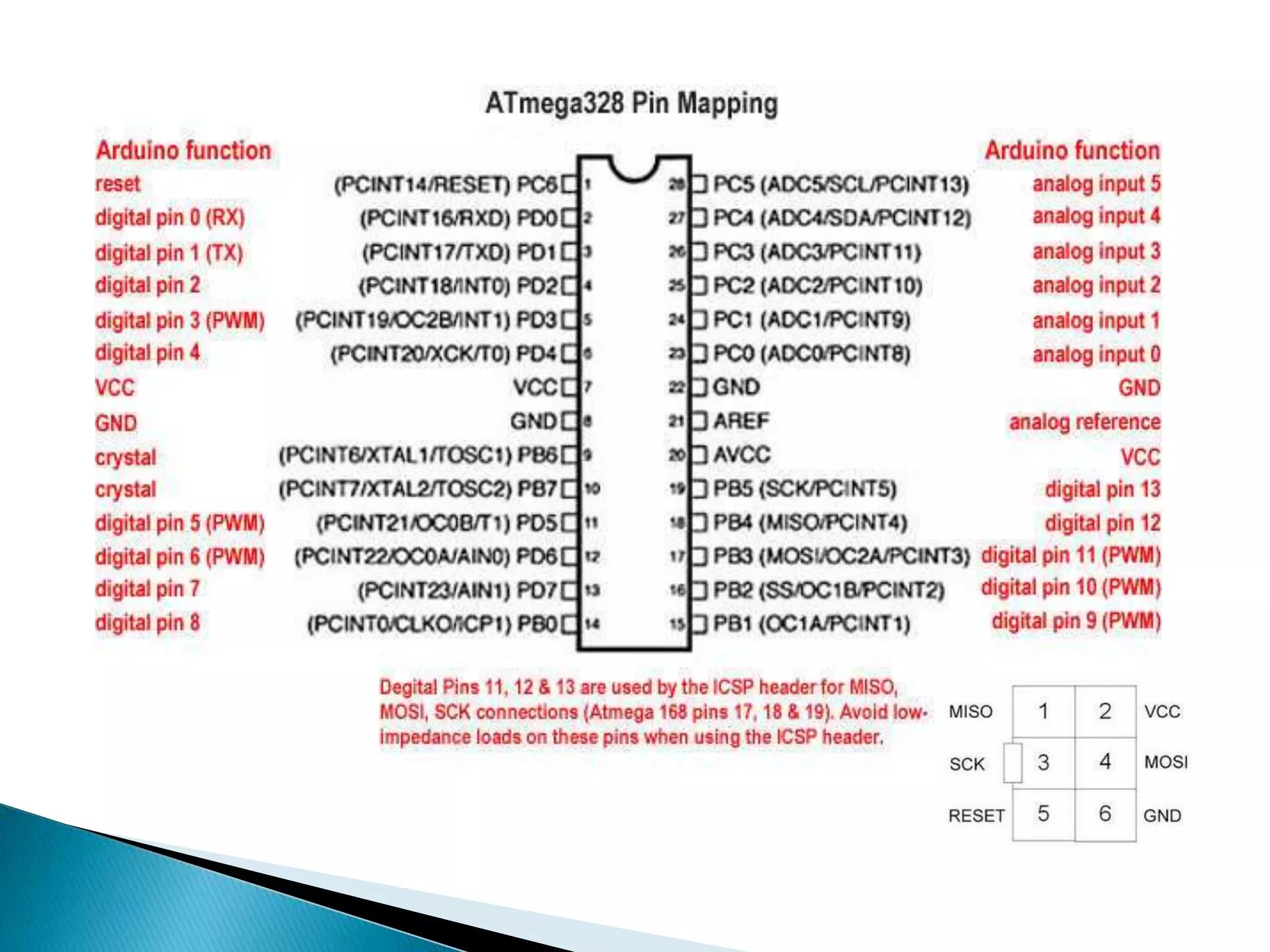
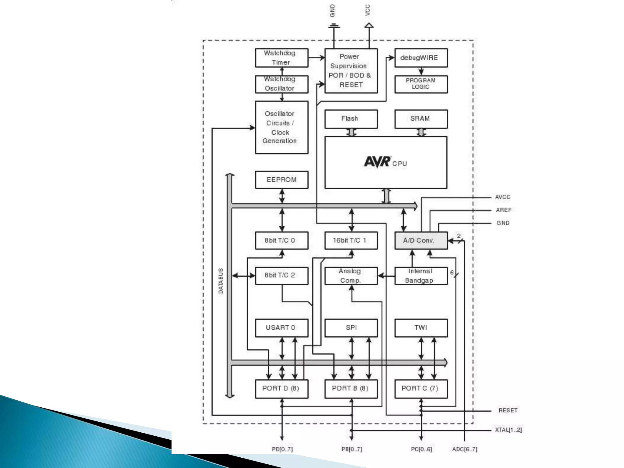
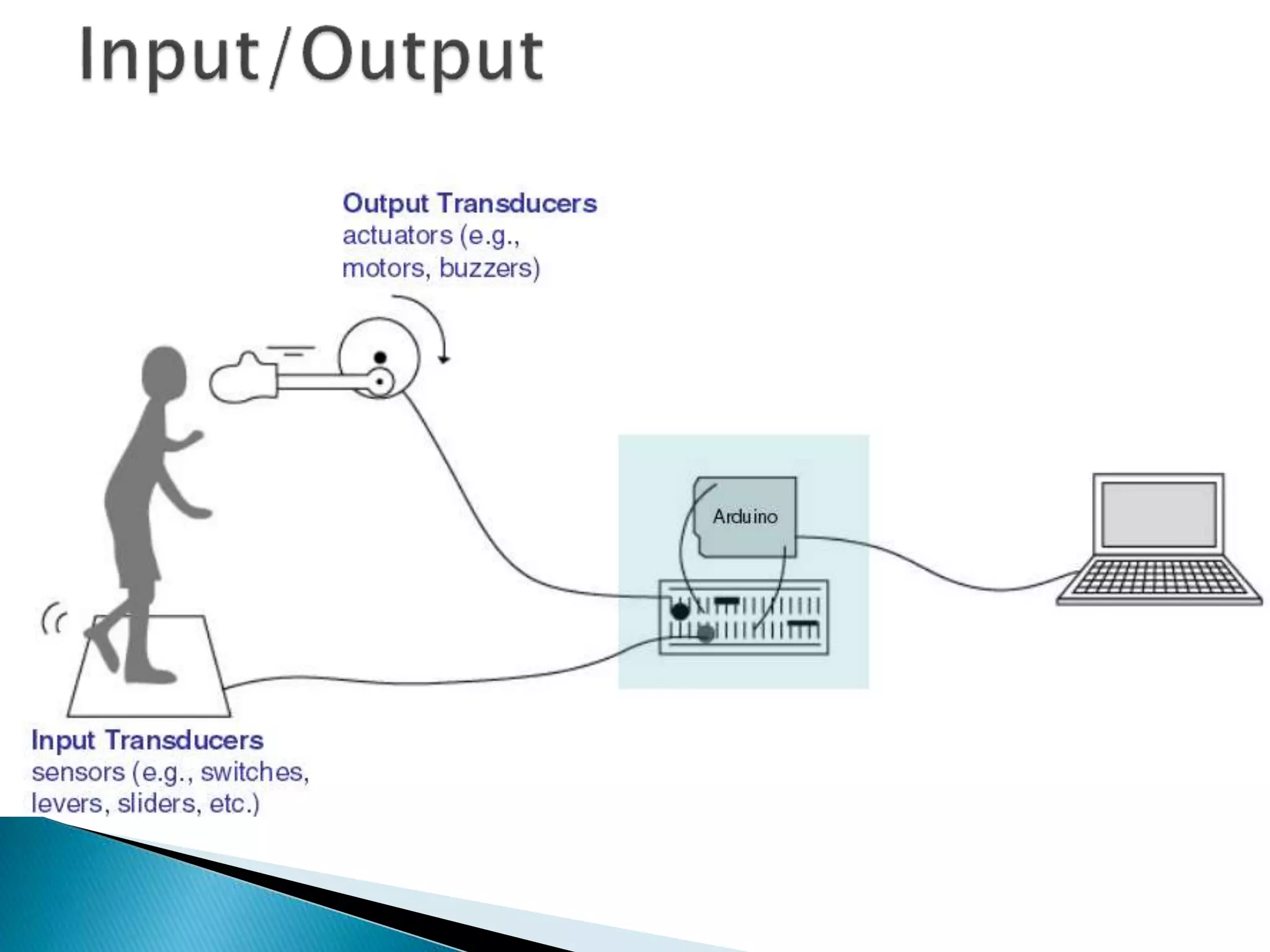
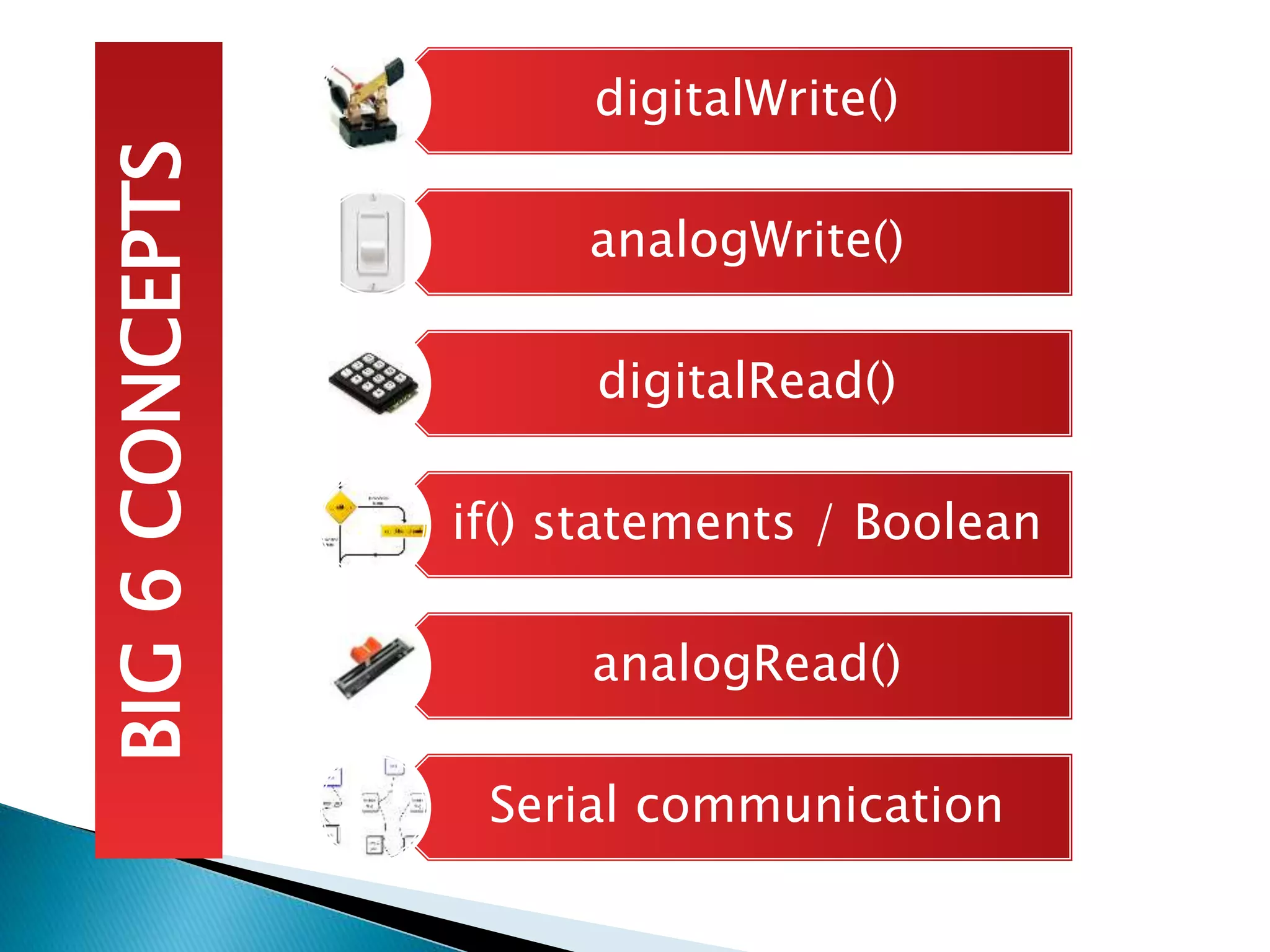
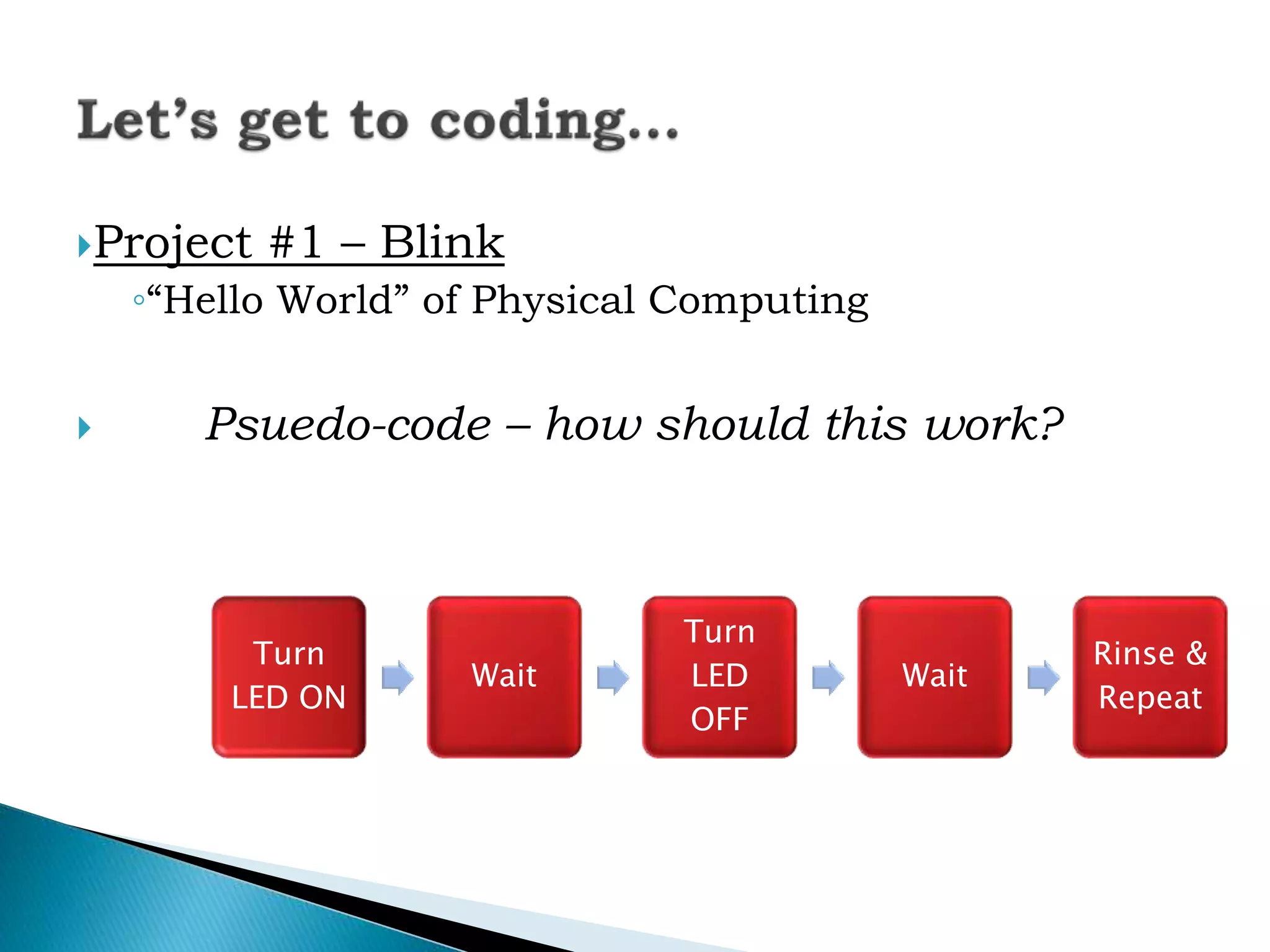
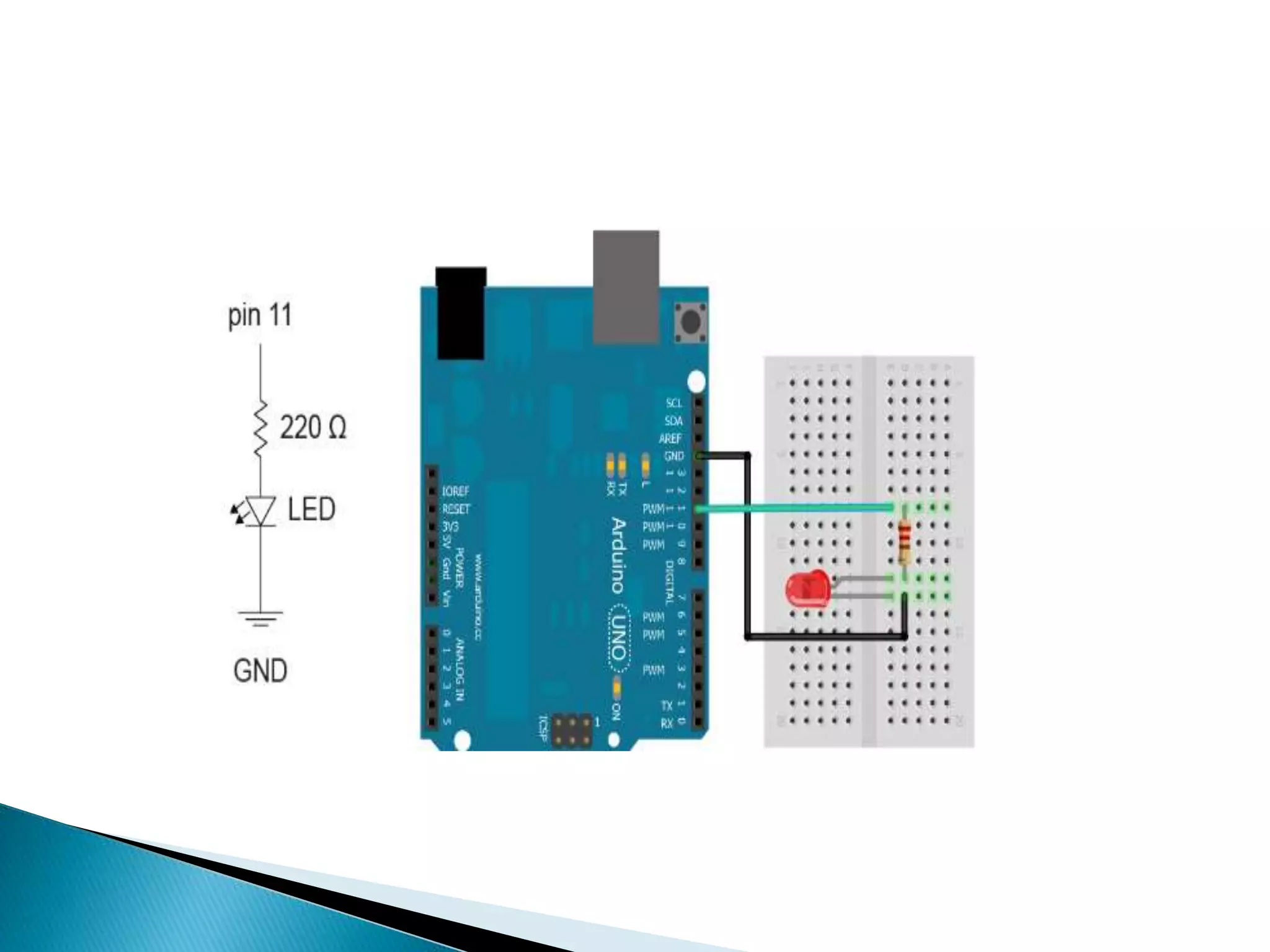
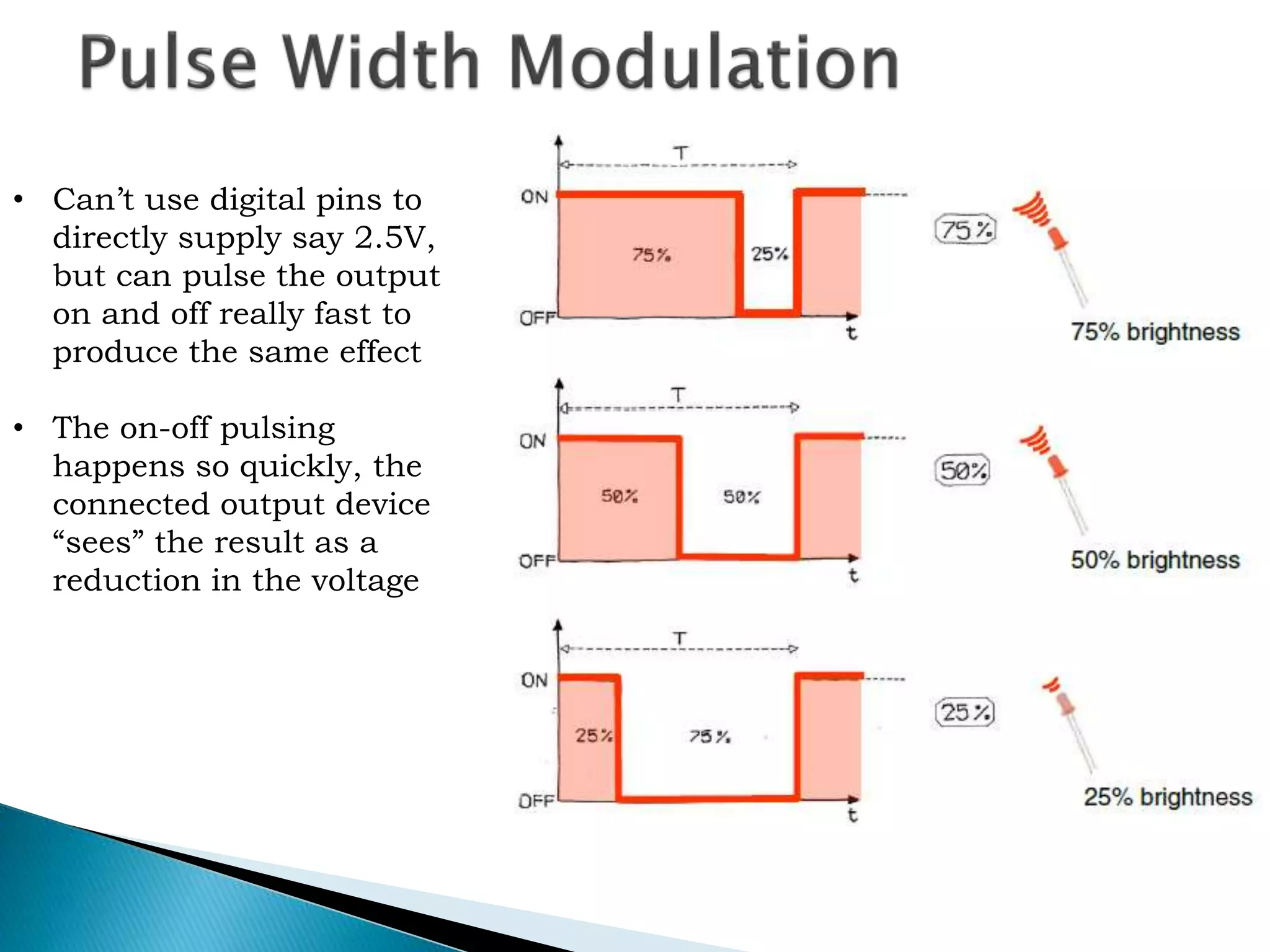
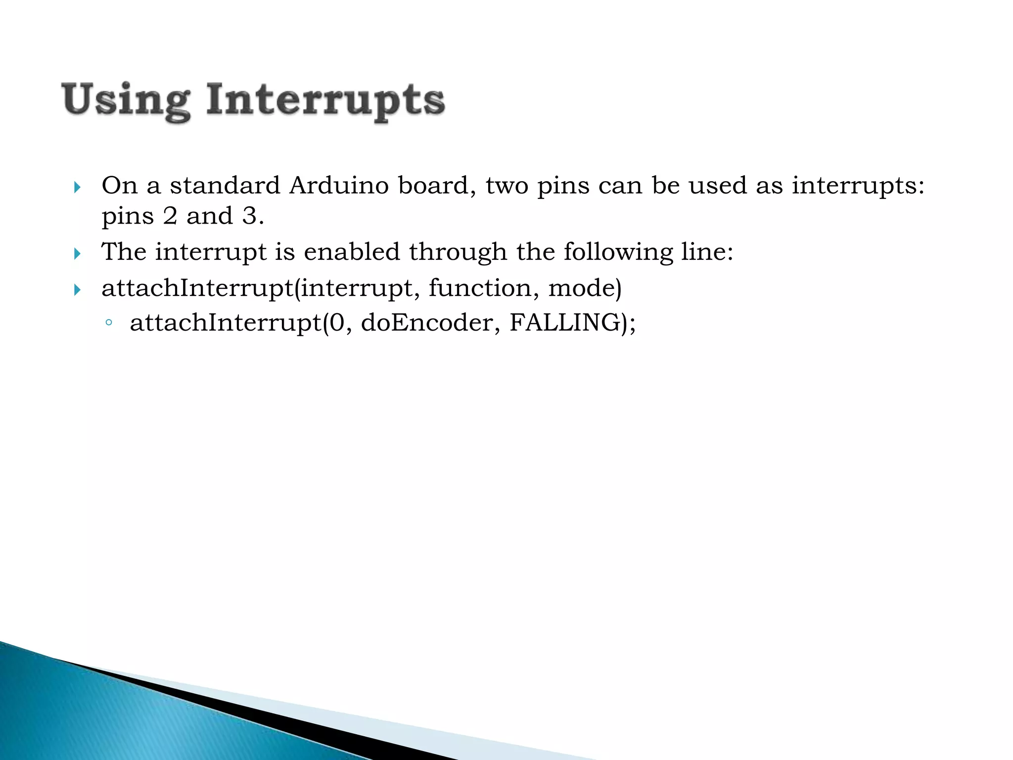
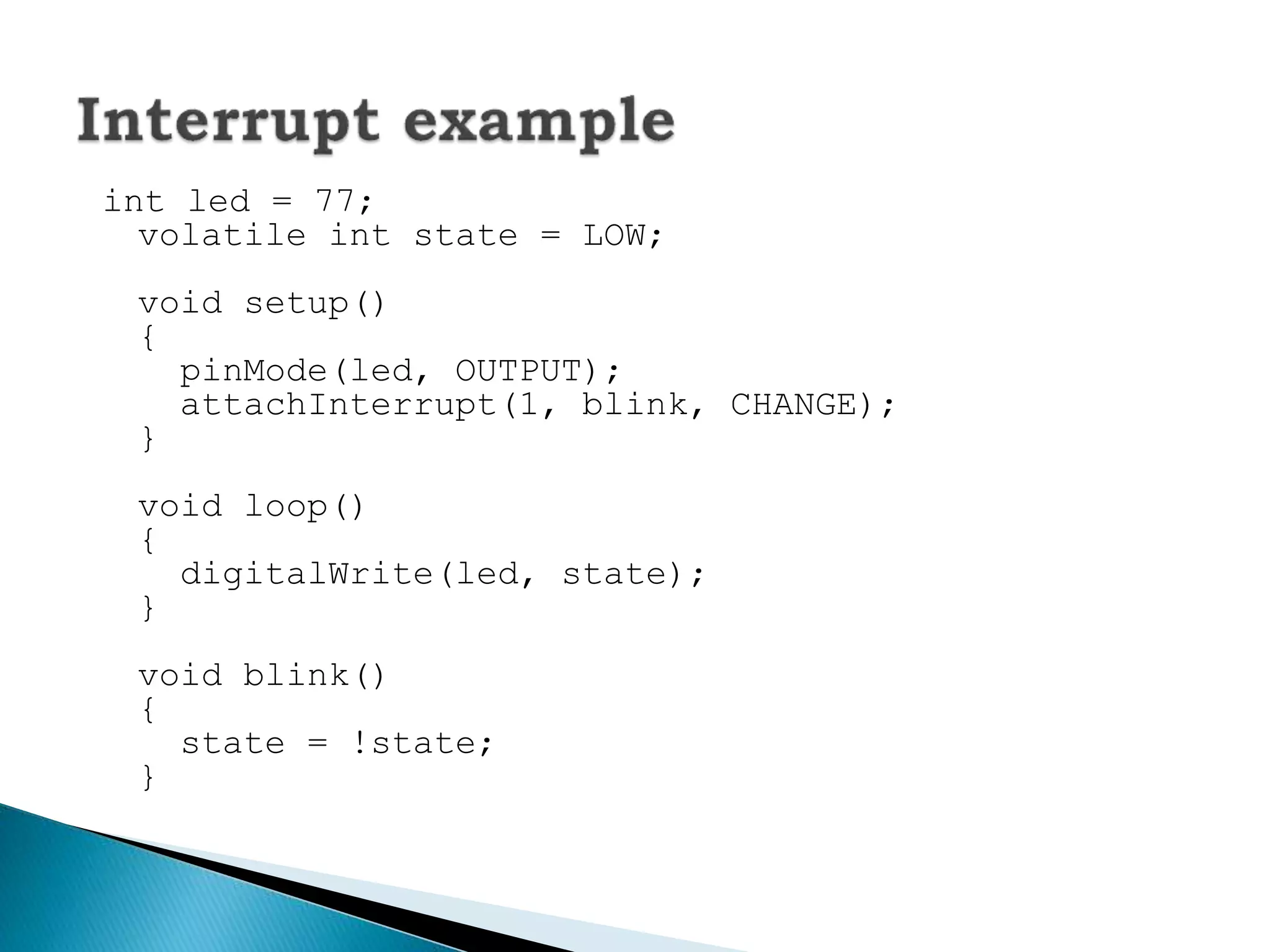
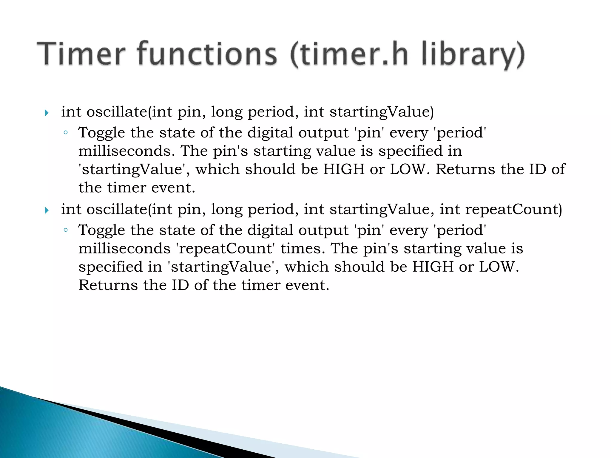
KEMBAR78
Arduino intro.pptx
 1. Basics
 Introduction to Microprocessor &
Microcontroller and Embedded Systems
 Analog and Digital I/O, Arduino board
description and TinkerCAD simulation.
 Learning Arduino Platform- IDE, development
board and Installation
2. Basic I/O devices
 LED’s, Switches
 PWM output
 Buzzer
 Seven Segment Display
 LCD
 DC motor
 Stepper motor
 Relays
 Basics of sensors and actuators
3. Sensor Interfacing
 Ultrasonic
 Proximity
 IR, LDR
 Gas, Smoke, Alcohol
 Rain, Temperature, Moisture / Humidity
 PIR Motion
 Accelerometer
 Vibration/ sound
 References
 1. Arduino-Based Embedded Systems: By Rajesh
Singh, Anita Gehlot, Bhupendra Singh, and
Sushabhan Choudhury.
 2. https ://www.arduino.cc/en/Tutorial/HomePage
 3. Arduino Made Simple by Ashwin Pajankar
https://spoken-tutorial.org/tutorial-
search/?search_foss=Arduino&search_language=Eng
lish
Computer on a single integrated chip
– Processor (CPU)
– Memory (RAM / ROM / Flash)
– I/O ports (USB, I2C, SPI, ADC)
Common microcontroller families:
– Intel: 4004, 8008, etc.
– Atmel: AT and AVR
– Microchip: PIC
– ARM: (multiple manufacturers)
Used in:
– Cell phones,
–Toys
– Household appliances
–Cars
– Cameras
 Open Source electronic prototyping platform based on
flexible easy to use hardware and software.
By Sebastian Goscik for EARS
Features
• 14 Digital I/O pins
• 6 Analogue inputs
• 6 PWM pins
• USB serial
• 16MHz Clock speed
• 32KB Flash memory
• 2KB SRAM
• 1KB EEPROM
Features
AVR 8-bit RISC architecture
Available in DIP package
Up to 20 MHz clock
Program Memory Type -Flash
Program Memory Size (KB) – 32
CPU Speed (MIPS/DMIPS) - 20
SRAM Bytes - 2,048
23 programmable I/O channels
Six 10-bit ADC inputs
Data EEPROM/HEF (bytes) - 1024
Digital Communication Peripherals -1-UART, 2-SPI, 1-I2C
Capture/Compare/PWM Peripherals -1 Input Capture, 1 CCP, 6PWM
Timers - 2 x 8-bit, 1 x 16-bit
Number of Comparators – 1
Operating Voltage Range (V) - 1.8 to 5.5
Pin Count - 32
TWI - I2C is a serial protocol for two-wire interface to connect low-speed
devices like microcontrollers, EEPROMs, A/D and D/A converters, I/O
interfaces and other similar peripherals in embedded systems
watchdog timer (sometimes called a computer operating properly or COP
timer, or simply a watchdog) is an electronic timer that is used to detect and
recover from computer malfunctions.
CCP Module
Capture - The contents of the 16 bit timer, upon detecting an n-th rising or falling edge, is written
to internal registers
Compare - Generate an interrupt, or change on output pin, when Timer 1 matches a preset
comparison value
PWM - -Create a reconfigurable steady duty cycle square wave output at a user set frequency
Download Arduino compiler and development environment
from:
http://arduino.cc/en/Main/Software
Available for:
 – Windows
 – MacOX
 – Linux
 Before running Arduino, plug in your board using USB
cable
(external power is not necessary)
By Sebastian Goscik for EARS
 Sensors ( to sense stuff ) – Push buttons, touch pads, tilt switches. –
Variable resistors (eg. volume knob / sliders) – Photoresistors
(sensing light levels) – Thermistors (temperature) – Ultrasound
(proximity range finder) • Actuators ( to do stuff ) – Lights, LED’s
 Motors – Speakers – Displays (LCD)
 Home Automations
 Sensor prototyping
 Robotics
 SP programming
 Easy Wifi ,Gsm ,Ethernet , Bluetooth , zigbee Conectivity
Declare variables at top
Initialize
setup() – run once at beginning, set
pins
Running
loop() – run repeatedly, after setup()
void setup() {
// put your setup code here, to run once:
}
void loop() {
// put your main code here, to run
repeatedly:
}
 A pin on arduino can be set as input or output by using
pinMode function.
 pinMode(13, OUTPUT); // sets pin 13 as output pin
 pinMode(13, INPUT); // sets pin 13 as input pin
digitalWrite()
analogWrite()
digitalRead()
if() statements / Boolean
analogRead()
Serial communication
BIG
6
CONCEPTS
Project #1 – Blink
◦“Hello World” of Physical Computing
 Psuedo-code – how should this work?
Turn
LED ON
Wait
Turn
LED
OFF
Wait
Rinse &
Repeat
 Serial.println(value);
◦ Prints the value to the Serial Monitor on your
computer
 pinMode(pin, mode);
◦ Configures a digital pin to read (input) or write
(output) a digital value
 digitalRead(pin);
◦ Reads a digital value (HIGH or LOW) on a pin set
for input
 digitalWrite(pin, value);
◦ Writes the digital value (HIGH or LOW) to a pin
set for output
 digitalWrite(13, LOW); // Makes the output voltage on pin 13
, 0V
 digitalWrite(13, HIGH); // Makes the output voltage on pin
13 , 5V
 int buttonState = digitalRead(2); // reads the value of pin 2
in buttonState
 What is analog ?
 It is continuous range of voltage values (not just 0 or 5V)
 Why convert to digital ?
 Because our microcontroller only understands digital.
 The Arduino Uno board contains 6 pins for ADC
 10-bit analog to digital converter
 This means that it will map input voltages between 0 and 5
volts into integer values between 0 and 1023
 analogRead(A0); // used to read the analog value
from the pin A0
 analogWrite(2,128);
Method used to transfer data between two devices.
Arduino dedicates Digital I/O pin # 0 to
receiving and Digital I/O pin #1 to
transmit.
Data passes between the computer and Arduino
through the USB cable. Data is transmitted as
zeros (‘0’) and ones (‘1’) sequentially.
PWM allows you to create a fake
analogue signal by toggling a pin high
and low. The amount of overall time the
pin spends high effects the average
voltage of the signal.
This works well for dimming LEDs so
long as the frequency of pulses is faster
than the eye can pick up
An Arduino UNO can only do PWM on
pins:
3, 5, 6, 9, 10 and 11
• Can’t use digital pins to
directly supply say 2.5V,
but can pulse the output
on and off really fast to
produce the same effect
• The on-off pulsing
happens so quickly, the
connected output device
“sees” the result as a
reduction in the voltage
• Command:
analogWrite(pin,value)
• value is duty cycle: between
0 and 255
• Examples:
analogWrite(9, 128)
for a 50% duty cycle
analogWrite(11, 64)
for a 25% duty cycle
 // These constants won't change. They're used to give names to the pins used:
const int analogInPin = A0; // Analog input pin that the potentiometer is attached to
const int analogOutPin = 9; // Analog output pin that the LED is attached to
int sensorValue = 0; // value read from the pot
int outputValue = 0; // value output to the PWM (analog out)
void setup() {
// initialize serial communications at 9600 bps:
Serial.begin(9600);
}
void loop() {
// read the analog in value:
sensorValue = analogRead(analogInPin);
// map it to the range of the analog out:
outputValue = map(sensorValue, 0, 1023, 0, 255);
// change the analog out value:
analogWrite(analogOutPin, outputValue);
// print the results to the serial monitor:
Serial.print("sensor = " );
Serial.print(sensorValue);
Serial.print("t output = ");
Serial.println(outputValue);
// wait 2 milliseconds before the next loop
// for the analog-to-digital converter to settle
// after the last reading:
delay(2);
}
 On a standard Arduino board, two pins can be used as interrupts:
pins 2 and 3.
 The interrupt is enabled through the following line:
 attachInterrupt(interrupt, function, mode)
◦ attachInterrupt(0, doEncoder, FALLING);
int led = 77;
volatile int state = LOW;
void setup()
{
pinMode(led, OUTPUT);
attachInterrupt(1, blink, CHANGE);
}
void loop()
{
digitalWrite(led, state);
}
void blink()
{
state = !state;
}
 int oscillate(int pin, long period, int startingValue)
◦ Toggle the state of the digital output 'pin' every 'period'
milliseconds. The pin's starting value is specified in
'startingValue', which should be HIGH or LOW. Returns the ID of
the timer event.
 int oscillate(int pin, long period, int startingValue, int repeatCount)
◦ Toggle the state of the digital output 'pin' every 'period'
milliseconds 'repeatCount' times. The pin's starting value is
specified in 'startingValue', which should be HIGH or LOW.
Returns the ID of the timer event.
 int pulse(int pin, long period, int startingValue)
◦ Toggle the state of the digital output 'pin' just once after 'period'
milliseconds. The pin's starting value is specified in
'startingValue', which should be HIGH or LOW. Returns the ID of
the timer event.
 int stop(int id)
◦ Stop the timer event running. Returns the ID of the timer event.
 int update()
◦ Must be called from 'loop'. This will service all the events
associated with the timer.
#include "Timer.h"
Timer t;
int ledEvent;
void setup()
{
Serial.begin(9600);
int tickEvent = t.every(2000, doSomething);
Serial.print("2 second tick started id=");
Serial.println(tickEvent);
pinMode(13, OUTPUT);
ledEvent = t.oscillate(13, 50, HIGH);
Serial.print("LED event started id=");
Serial.println(ledEvent);
int afterEvent = t.after(10000, doAfter);
Serial.print("After event started id=");
Serial.println(afterEvent);
}
void loop()
{
t.update();
}
void doSomething()
{
Serial.print("2 second tick: millis()=");
Serial.println(millis());
}
void doAfter()
{
Serial.println("stop the led event");
t.stop(ledEvent);
t.oscillate(13, 500, HIGH, 5);
}

Arduino intro.pptx

  • 1.
     1. Basics Introduction to Microprocessor & Microcontroller and Embedded Systems  Analog and Digital I/O, Arduino board description and TinkerCAD simulation.  Learning Arduino Platform- IDE, development board and Installation
  • 2.
    2. Basic I/Odevices  LED’s, Switches  PWM output  Buzzer  Seven Segment Display  LCD  DC motor  Stepper motor  Relays  Basics of sensors and actuators
  • 3.
    3. Sensor Interfacing Ultrasonic  Proximity  IR, LDR  Gas, Smoke, Alcohol  Rain, Temperature, Moisture / Humidity  PIR Motion  Accelerometer  Vibration/ sound
  • 4.
     References  1.Arduino-Based Embedded Systems: By Rajesh Singh, Anita Gehlot, Bhupendra Singh, and Sushabhan Choudhury.  2. https ://www.arduino.cc/en/Tutorial/HomePage  3. Arduino Made Simple by Ashwin Pajankar https://spoken-tutorial.org/tutorial- search/?search_foss=Arduino&search_language=Eng lish
  • 5.
    Computer on asingle integrated chip – Processor (CPU) – Memory (RAM / ROM / Flash) – I/O ports (USB, I2C, SPI, ADC) Common microcontroller families: – Intel: 4004, 8008, etc. – Atmel: AT and AVR – Microchip: PIC – ARM: (multiple manufacturers) Used in: – Cell phones, –Toys – Household appliances –Cars – Cameras
  • 6.
     Open Sourceelectronic prototyping platform based on flexible easy to use hardware and software.
  • 8.
    By Sebastian Goscikfor EARS Features • 14 Digital I/O pins • 6 Analogue inputs • 6 PWM pins • USB serial • 16MHz Clock speed • 32KB Flash memory • 2KB SRAM • 1KB EEPROM
  • 14.
    Features AVR 8-bit RISCarchitecture Available in DIP package Up to 20 MHz clock Program Memory Type -Flash Program Memory Size (KB) – 32 CPU Speed (MIPS/DMIPS) - 20 SRAM Bytes - 2,048 23 programmable I/O channels Six 10-bit ADC inputs Data EEPROM/HEF (bytes) - 1024 Digital Communication Peripherals -1-UART, 2-SPI, 1-I2C Capture/Compare/PWM Peripherals -1 Input Capture, 1 CCP, 6PWM Timers - 2 x 8-bit, 1 x 16-bit Number of Comparators – 1 Operating Voltage Range (V) - 1.8 to 5.5 Pin Count - 32
  • 15.
    TWI - I2Cis a serial protocol for two-wire interface to connect low-speed devices like microcontrollers, EEPROMs, A/D and D/A converters, I/O interfaces and other similar peripherals in embedded systems watchdog timer (sometimes called a computer operating properly or COP timer, or simply a watchdog) is an electronic timer that is used to detect and recover from computer malfunctions. CCP Module Capture - The contents of the 16 bit timer, upon detecting an n-th rising or falling edge, is written to internal registers Compare - Generate an interrupt, or change on output pin, when Timer 1 matches a preset comparison value PWM - -Create a reconfigurable steady duty cycle square wave output at a user set frequency
  • 16.
    Download Arduino compilerand development environment from: http://arduino.cc/en/Main/Software Available for:  – Windows  – MacOX  – Linux  Before running Arduino, plug in your board using USB cable (external power is not necessary)
  • 19.
  • 22.
     Sensors (to sense stuff ) – Push buttons, touch pads, tilt switches. – Variable resistors (eg. volume knob / sliders) – Photoresistors (sensing light levels) – Thermistors (temperature) – Ultrasound (proximity range finder) • Actuators ( to do stuff ) – Lights, LED’s  Motors – Speakers – Displays (LCD)
  • 23.
     Home Automations Sensor prototyping  Robotics  SP programming  Easy Wifi ,Gsm ,Ethernet , Bluetooth , zigbee Conectivity
  • 25.
    Declare variables attop Initialize setup() – run once at beginning, set pins Running loop() – run repeatedly, after setup()
  • 26.
    void setup() { //put your setup code here, to run once: } void loop() { // put your main code here, to run repeatedly: }
  • 27.
     A pinon arduino can be set as input or output by using pinMode function.  pinMode(13, OUTPUT); // sets pin 13 as output pin  pinMode(13, INPUT); // sets pin 13 as input pin
  • 28.
    digitalWrite() analogWrite() digitalRead() if() statements /Boolean analogRead() Serial communication BIG 6 CONCEPTS
  • 29.
    Project #1 –Blink ◦“Hello World” of Physical Computing  Psuedo-code – how should this work? Turn LED ON Wait Turn LED OFF Wait Rinse & Repeat
  • 31.
     Serial.println(value); ◦ Printsthe value to the Serial Monitor on your computer  pinMode(pin, mode); ◦ Configures a digital pin to read (input) or write (output) a digital value  digitalRead(pin); ◦ Reads a digital value (HIGH or LOW) on a pin set for input  digitalWrite(pin, value); ◦ Writes the digital value (HIGH or LOW) to a pin set for output
  • 32.
     digitalWrite(13, LOW);// Makes the output voltage on pin 13 , 0V  digitalWrite(13, HIGH); // Makes the output voltage on pin 13 , 5V  int buttonState = digitalRead(2); // reads the value of pin 2 in buttonState
  • 33.
     What isanalog ?  It is continuous range of voltage values (not just 0 or 5V)  Why convert to digital ?  Because our microcontroller only understands digital.
  • 35.
     The ArduinoUno board contains 6 pins for ADC  10-bit analog to digital converter  This means that it will map input voltages between 0 and 5 volts into integer values between 0 and 1023
  • 36.
     analogRead(A0); //used to read the analog value from the pin A0  analogWrite(2,128);
  • 37.
    Method used totransfer data between two devices. Arduino dedicates Digital I/O pin # 0 to receiving and Digital I/O pin #1 to transmit. Data passes between the computer and Arduino through the USB cable. Data is transmitted as zeros (‘0’) and ones (‘1’) sequentially.
  • 38.
    PWM allows youto create a fake analogue signal by toggling a pin high and low. The amount of overall time the pin spends high effects the average voltage of the signal. This works well for dimming LEDs so long as the frequency of pulses is faster than the eye can pick up An Arduino UNO can only do PWM on pins: 3, 5, 6, 9, 10 and 11
  • 39.
    • Can’t usedigital pins to directly supply say 2.5V, but can pulse the output on and off really fast to produce the same effect • The on-off pulsing happens so quickly, the connected output device “sees” the result as a reduction in the voltage
  • 40.
    • Command: analogWrite(pin,value) • valueis duty cycle: between 0 and 255 • Examples: analogWrite(9, 128) for a 50% duty cycle analogWrite(11, 64) for a 25% duty cycle
  • 41.
     // Theseconstants won't change. They're used to give names to the pins used: const int analogInPin = A0; // Analog input pin that the potentiometer is attached to const int analogOutPin = 9; // Analog output pin that the LED is attached to int sensorValue = 0; // value read from the pot int outputValue = 0; // value output to the PWM (analog out) void setup() { // initialize serial communications at 9600 bps: Serial.begin(9600); } void loop() { // read the analog in value: sensorValue = analogRead(analogInPin); // map it to the range of the analog out: outputValue = map(sensorValue, 0, 1023, 0, 255); // change the analog out value: analogWrite(analogOutPin, outputValue); // print the results to the serial monitor: Serial.print("sensor = " ); Serial.print(sensorValue); Serial.print("t output = "); Serial.println(outputValue); // wait 2 milliseconds before the next loop // for the analog-to-digital converter to settle // after the last reading: delay(2); }
  • 42.
     On astandard Arduino board, two pins can be used as interrupts: pins 2 and 3.  The interrupt is enabled through the following line:  attachInterrupt(interrupt, function, mode) ◦ attachInterrupt(0, doEncoder, FALLING);
  • 43.
    int led =77; volatile int state = LOW; void setup() { pinMode(led, OUTPUT); attachInterrupt(1, blink, CHANGE); } void loop() { digitalWrite(led, state); } void blink() { state = !state; }
  • 44.
     int oscillate(intpin, long period, int startingValue) ◦ Toggle the state of the digital output 'pin' every 'period' milliseconds. The pin's starting value is specified in 'startingValue', which should be HIGH or LOW. Returns the ID of the timer event.  int oscillate(int pin, long period, int startingValue, int repeatCount) ◦ Toggle the state of the digital output 'pin' every 'period' milliseconds 'repeatCount' times. The pin's starting value is specified in 'startingValue', which should be HIGH or LOW. Returns the ID of the timer event.
  • 45.
     int pulse(intpin, long period, int startingValue) ◦ Toggle the state of the digital output 'pin' just once after 'period' milliseconds. The pin's starting value is specified in 'startingValue', which should be HIGH or LOW. Returns the ID of the timer event.  int stop(int id) ◦ Stop the timer event running. Returns the ID of the timer event.  int update() ◦ Must be called from 'loop'. This will service all the events associated with the timer.
  • 46.
    #include "Timer.h" Timer t; intledEvent; void setup() { Serial.begin(9600); int tickEvent = t.every(2000, doSomething); Serial.print("2 second tick started id="); Serial.println(tickEvent); pinMode(13, OUTPUT); ledEvent = t.oscillate(13, 50, HIGH); Serial.print("LED event started id="); Serial.println(ledEvent); int afterEvent = t.after(10000, doAfter); Serial.print("After event started id="); Serial.println(afterEvent); }
  • 47.
    void loop() { t.update(); } void doSomething() { Serial.print("2second tick: millis()="); Serial.println(millis()); } void doAfter() { Serial.println("stop the led event"); t.stop(ledEvent); t.oscillate(13, 500, HIGH, 5); }