Downloaded 207 times


![Five Execution Steps
Step name
Action for R-type
instructions
Action for Memoryreference Instructions
Action for
branches
Instruction fetch
IR = MEM[PC]
PC = PC + 4
Instruction decode/ register
fetch
Action for
jumps
A = Reg[IR[25-21]]
B = Reg[IR[20-16]]
ALUOut = PC + (sign extend (IR[15-0])<<2)
Execution, address
computation, branch/jump
completion
ALUOut = A op B
ALUOut = A+sign
extend(IR[15-0])
Memory access or R-type
completion
Reg[IR[15-11]] =
ALUOut
Load:MDR =Mem[ALUOut]
or
Store:Mem[ALUOut] = B
Memory read completion
Load: Reg[IR[20-16]] =
MDR
IF(A==B) Then
PC=ALUOut
PC=PC[3128]||(IR[250]<<2)](https://image.slidesharecdn.com/basicstructureofcomputers-140206030905-phpapp01/85/Basic-structure-of-computers-9-320.jpg)


![Five Execution Steps
Step name
Action for R-type
instructions
Action for Memoryreference Instructions
Action for
branches
Instruction fetch
IR = MEM[PC]
PC = PC + 4
Instruction decode/ register
fetch
Action for
jumps
A = Reg[IR[25-21]]
B = Reg[IR[20-16]]
ALUOut = PC + (sign extend (IR[15-0])<<2)
Execution, address
computation, branch/jump
completion
ALUOut = A op B
ALUOut = A+sign
extend(IR[15-0])
Memory access or R-type
completion
Reg[IR[15-11]] =
ALUOut
Load:MDR =Mem[ALUOut]
or
Store:Mem[ALUOut] = B
Memory read completion
Load: Reg[IR[20-16]] =
MDR
IF(A==B) Then
PC=ALUOut
PC=PC[3128]||(IR[250]<<2)](https://image.slidesharecdn.com/basicstructureofcomputers-140206030905-phpapp01/75/Basic-structure-of-computers-9-2048.jpg)
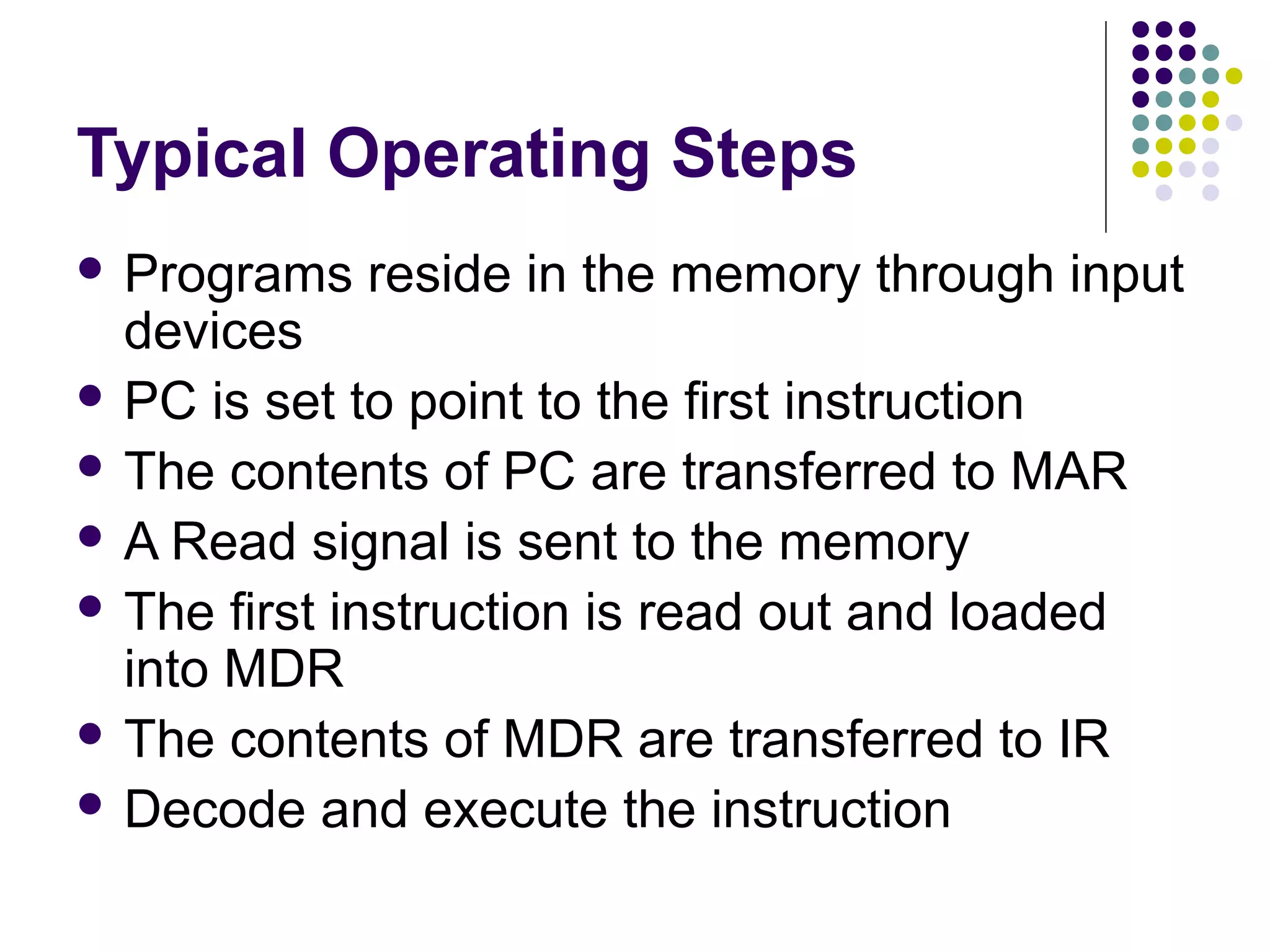


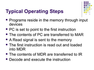
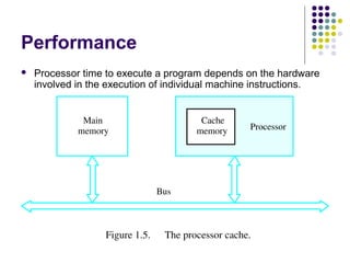
The document summarizes the basic functional units and operations of a computer system. It describes how a computer contains a central processing unit (CPU) that includes an arithmetic logic unit (ALU) and control unit to execute instructions. A computer also has memory to store programs and data, and input/output (I/O) devices to accept and output information. The CPU fetches instructions from memory, retrieves operands from memory or registers, performs operations in the ALU, and stores results back to memory or registers. The control unit coordinates the flow of data and execution of instructions. Performance can be improved by increasing clock speed, reducing the number of steps per instruction through pipelining and superscalar techniques, and optimizing compilers
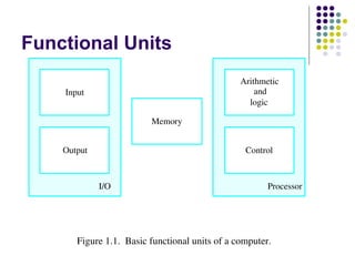
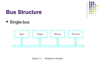
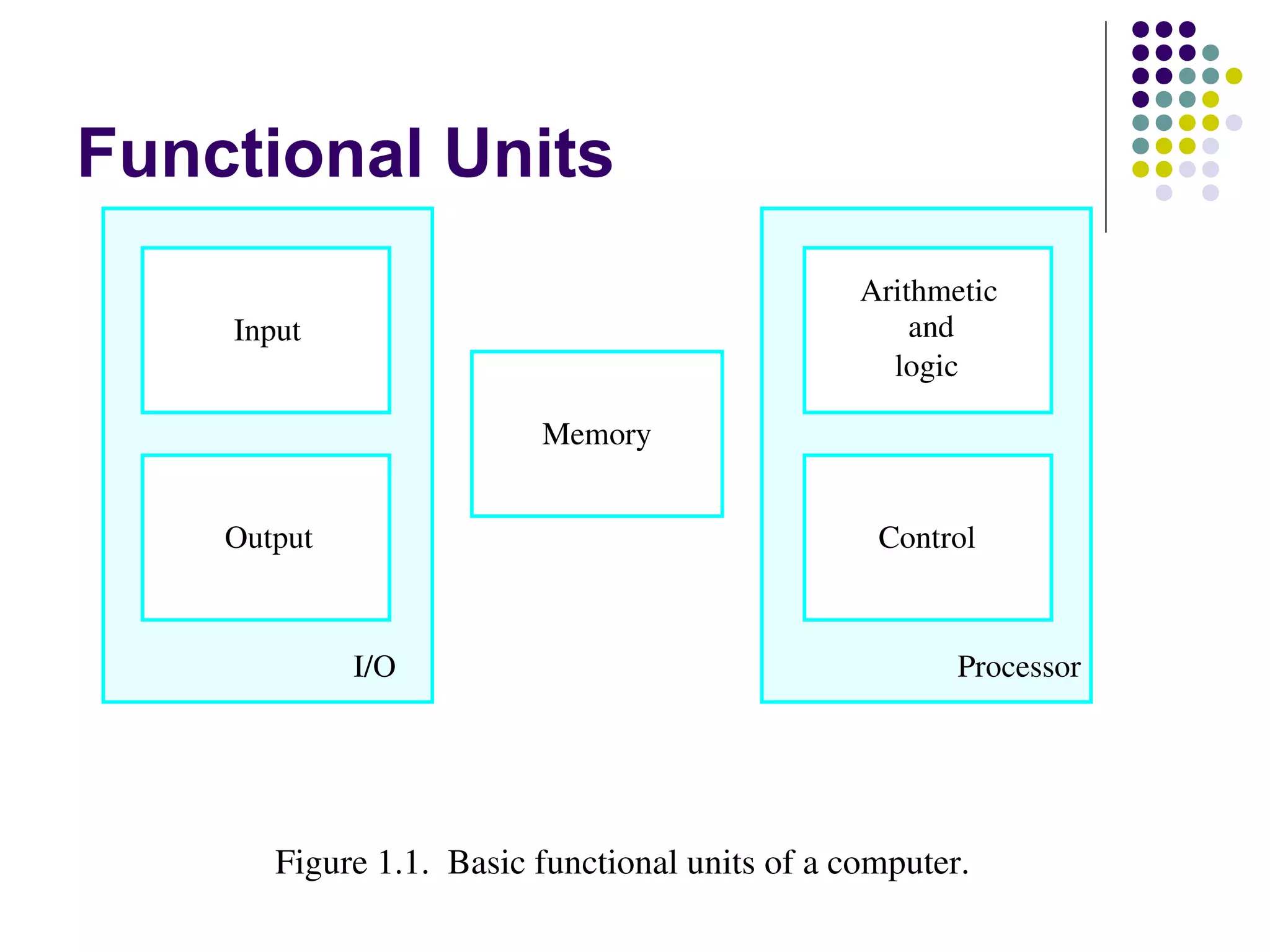
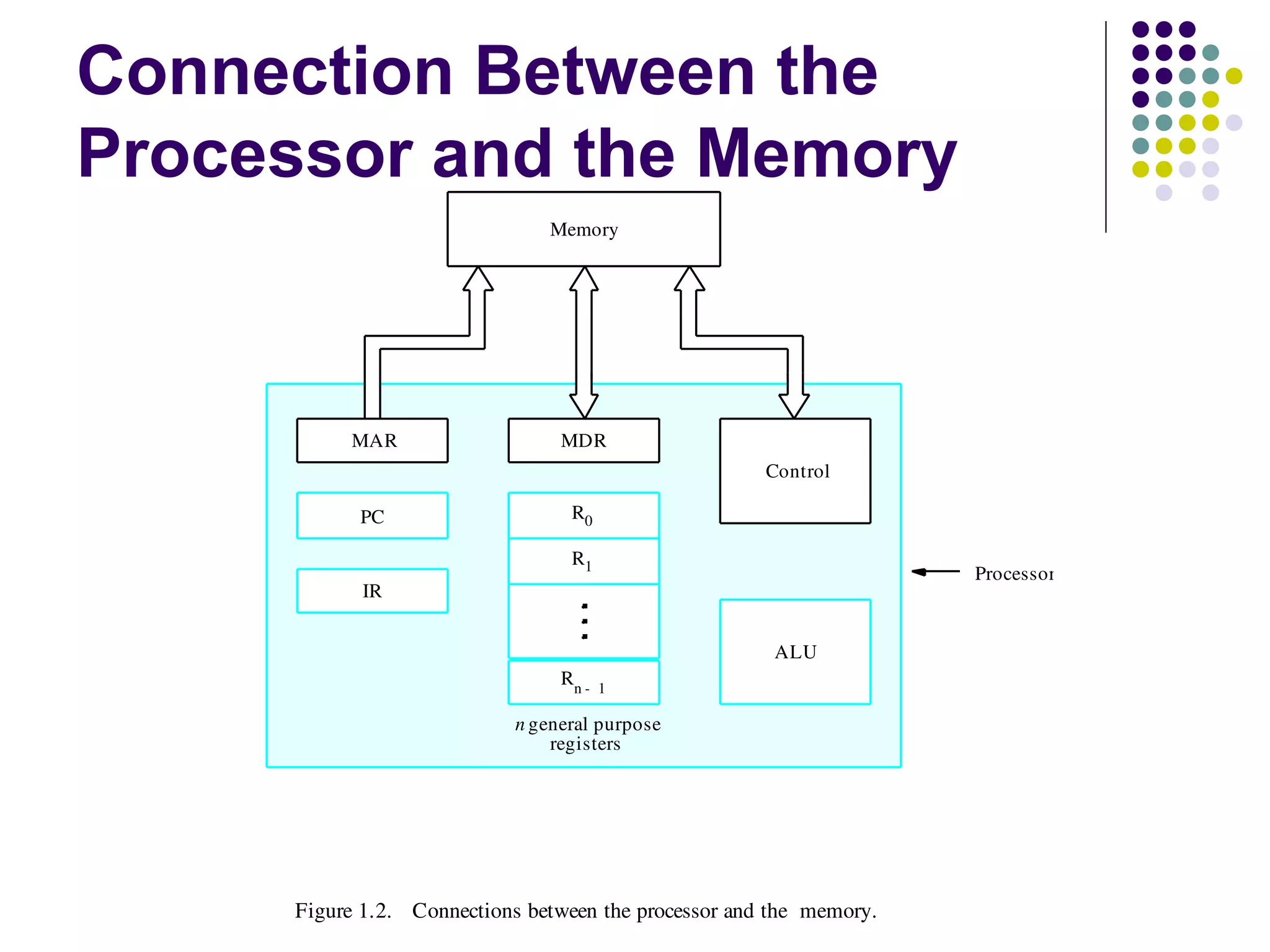
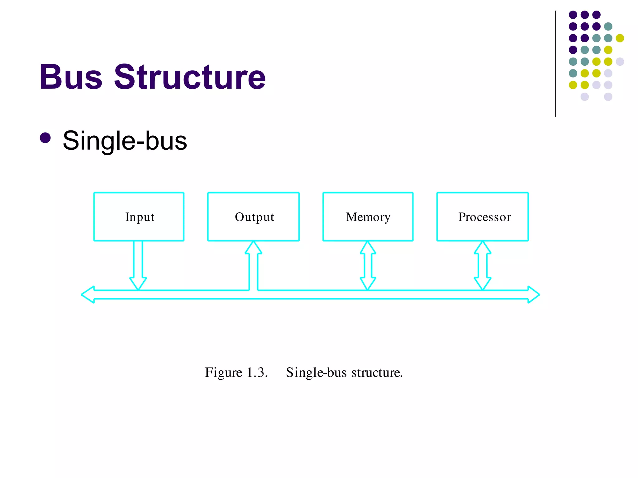
Overview of computer structure focusing on functional units: Input, Output, Control, Memory, and Processor.
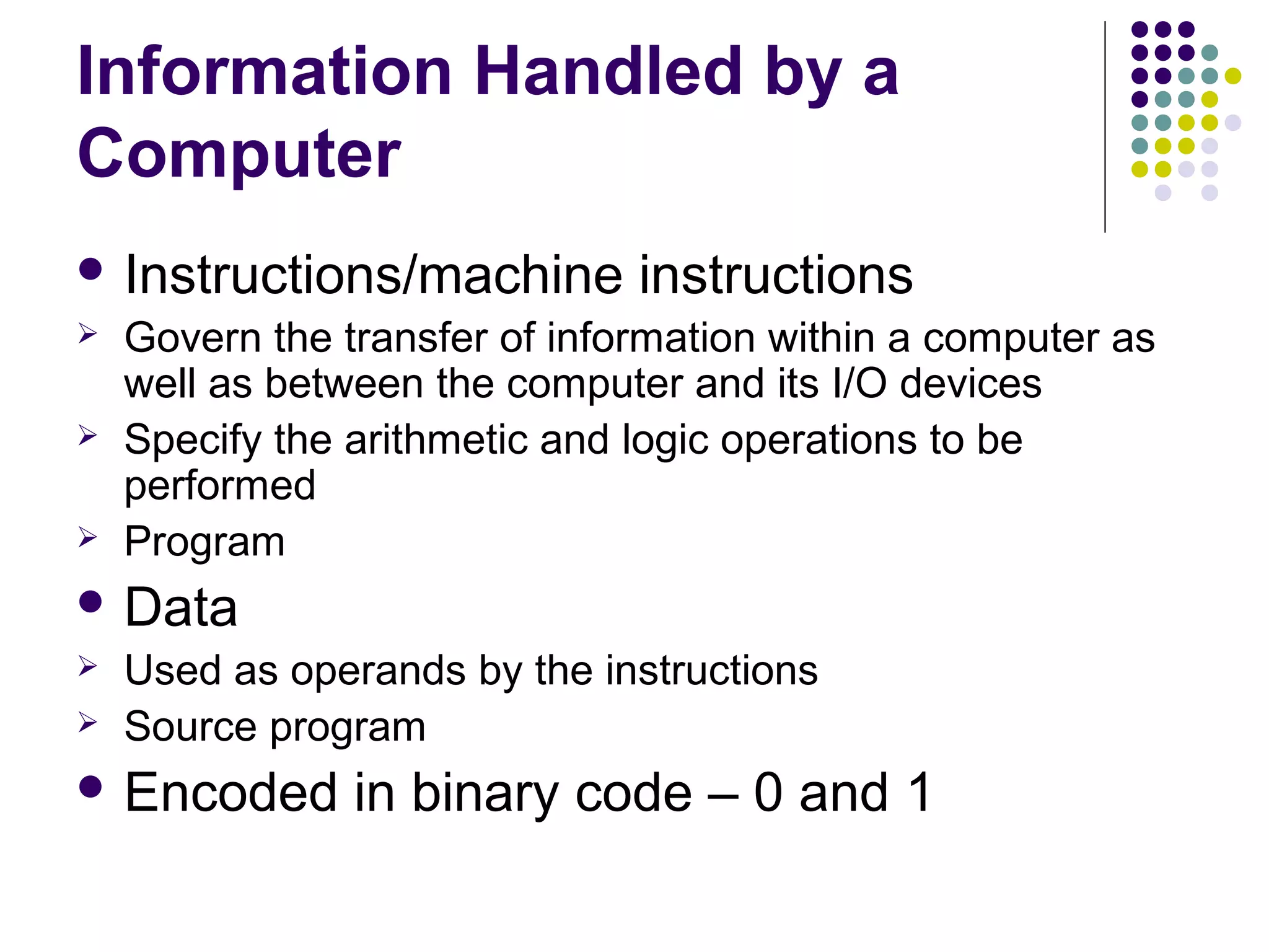
Explanation of data and instructions used by computers, including their representation in binary.
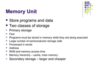
Description of Memory Unit categories: Primary (fast, necessary for operations) and Secondary (larger, cheaper storage).
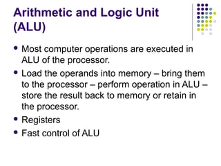
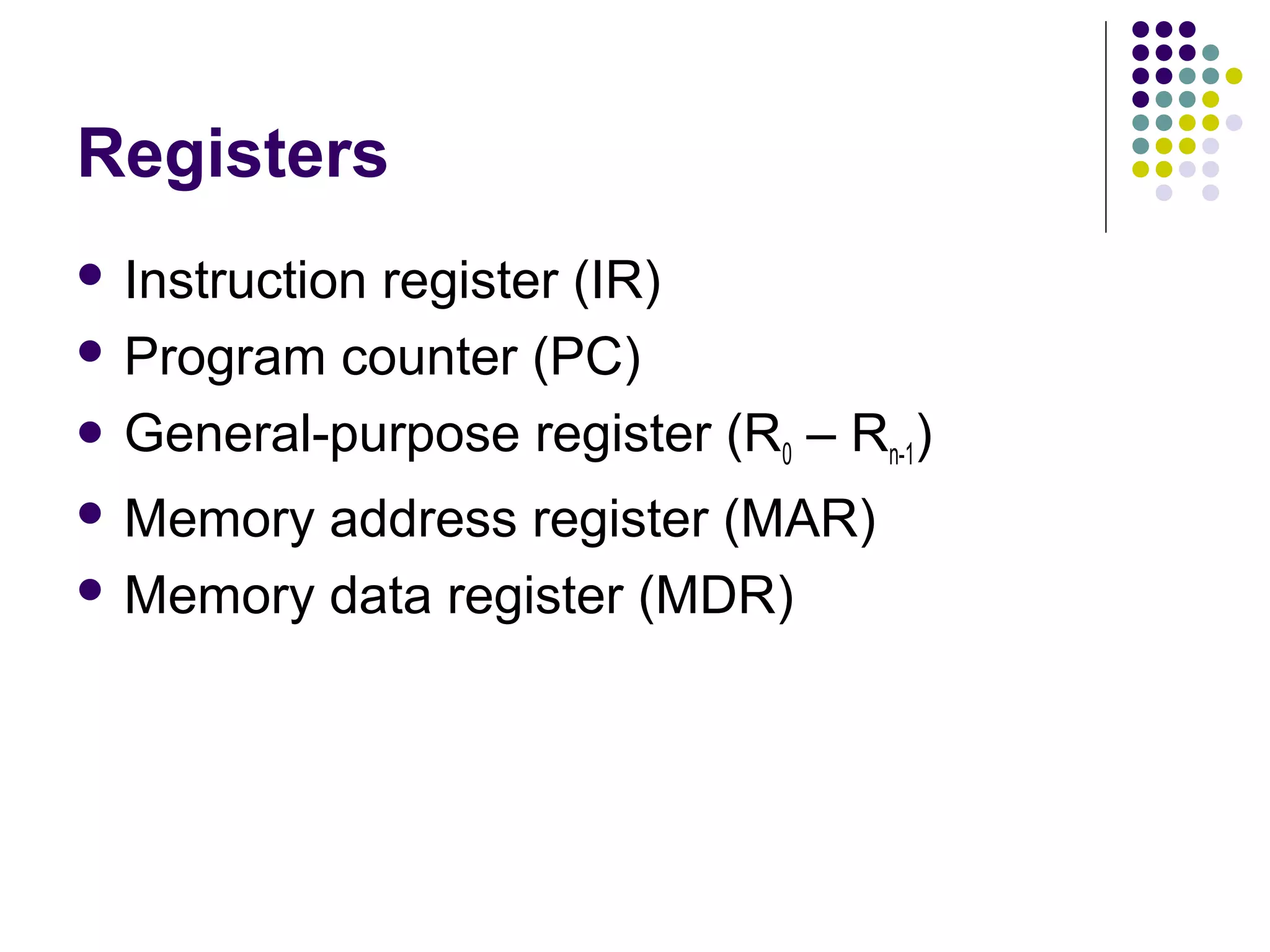
Details on processor functions, including Data Path, ALU, Control Unit, and interconnections with memory.
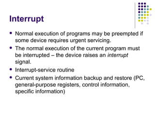
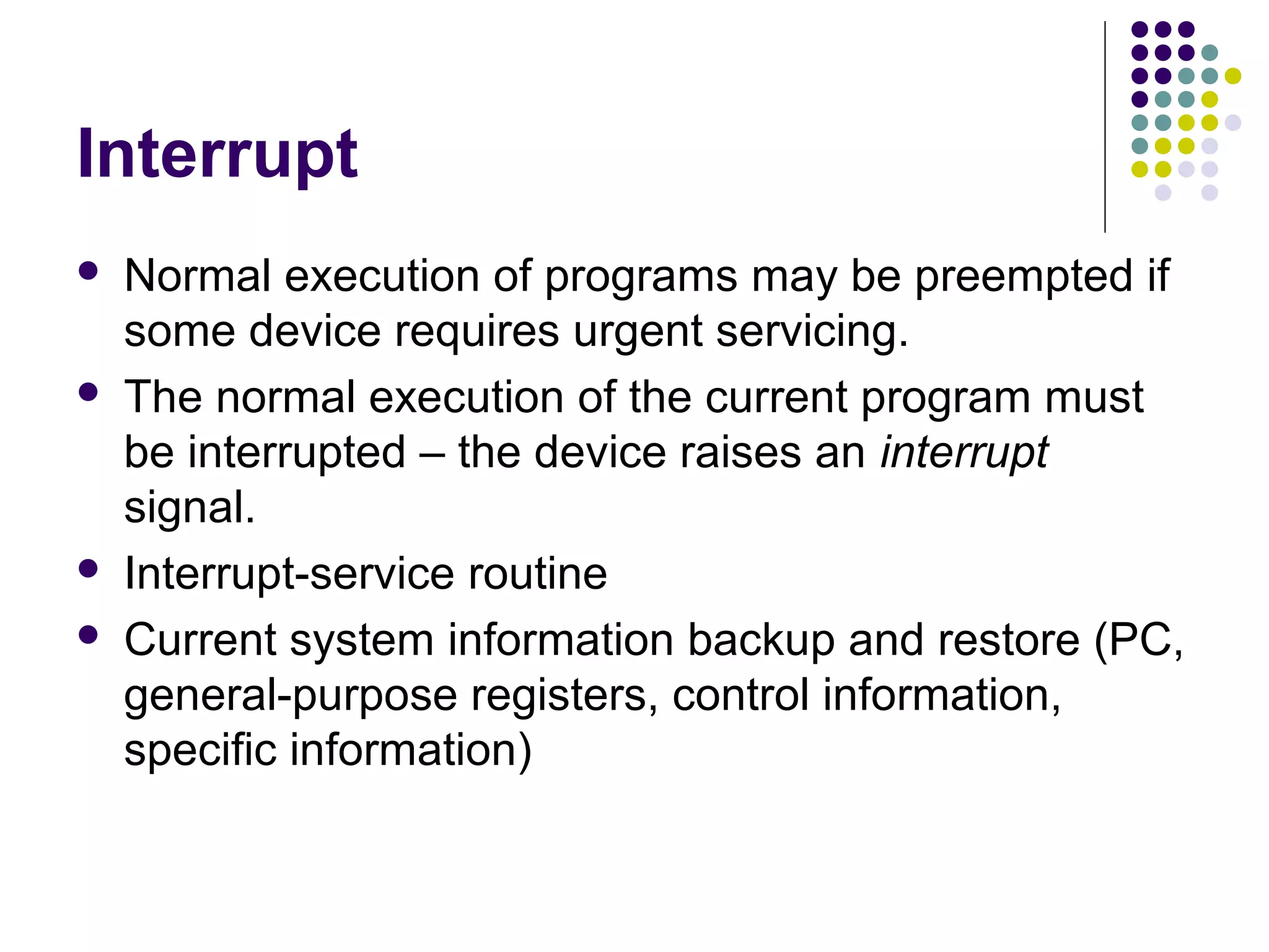
Understanding interrupts and the need for interrupt-service routines in normal program execution.
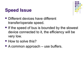
Explains bus structures for connecting the different parts of a computer and its impact on performance.
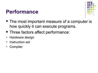
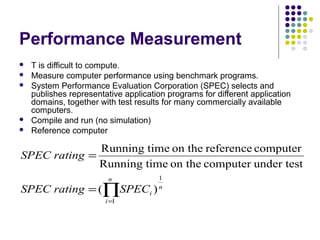
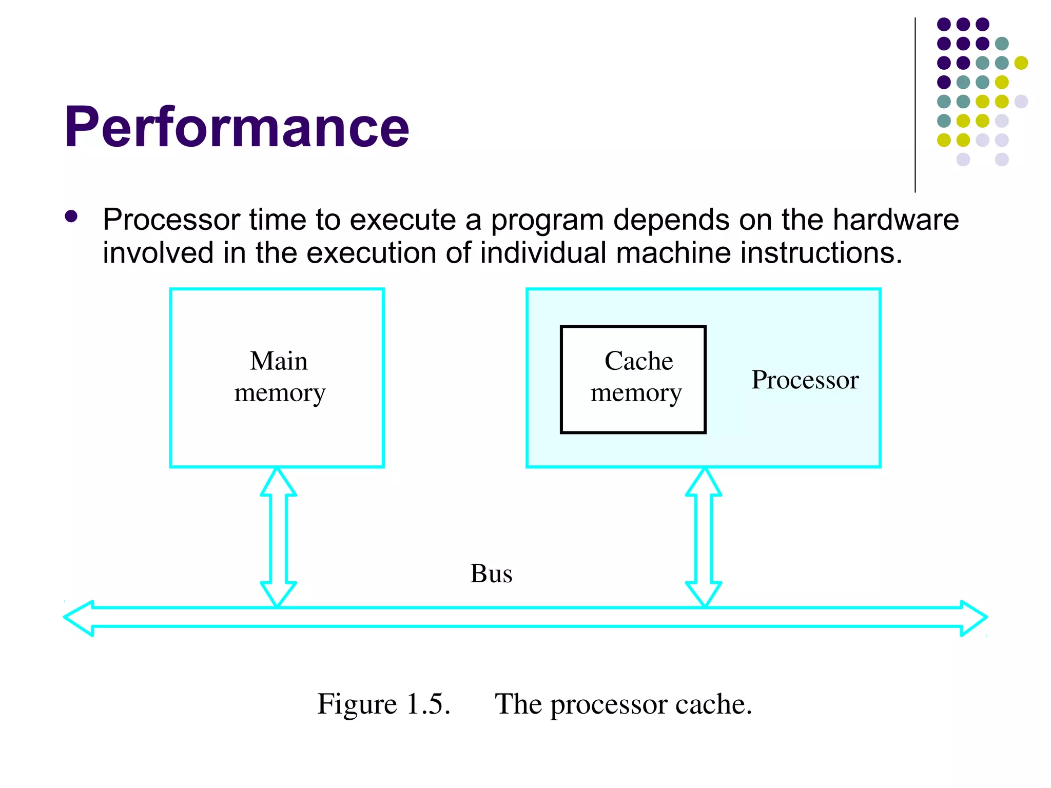
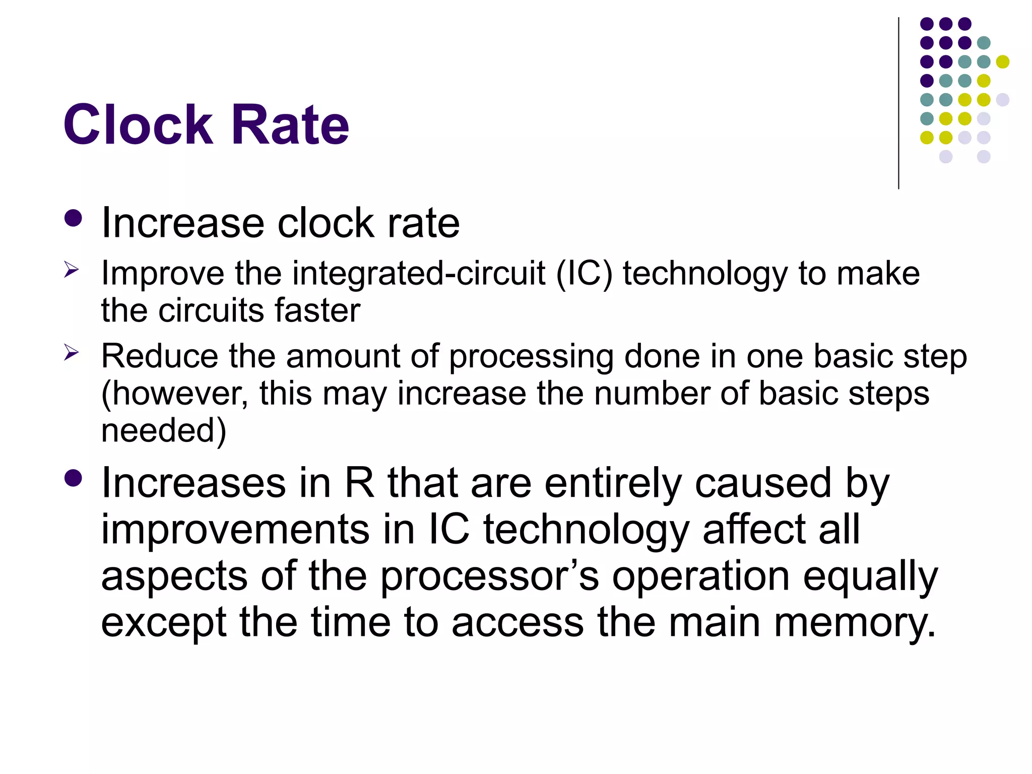
Discussion on performance, influenced by speed, hardware design, compiler efficiency, and clock speed.
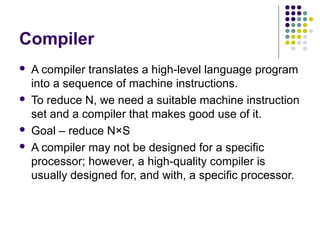
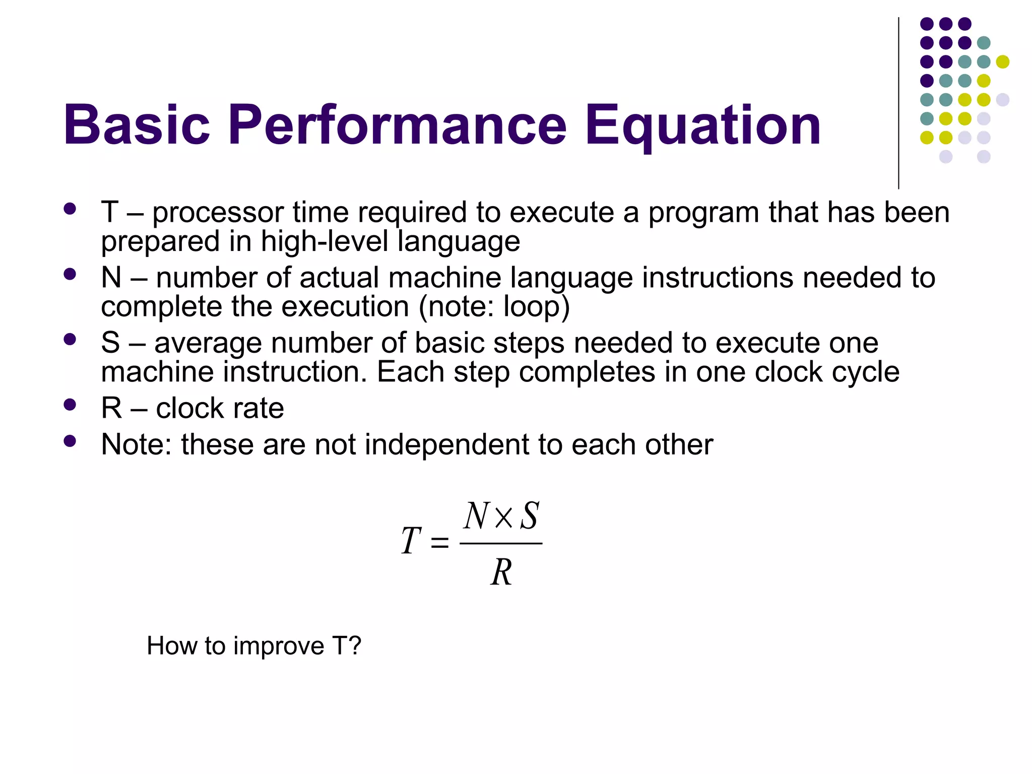
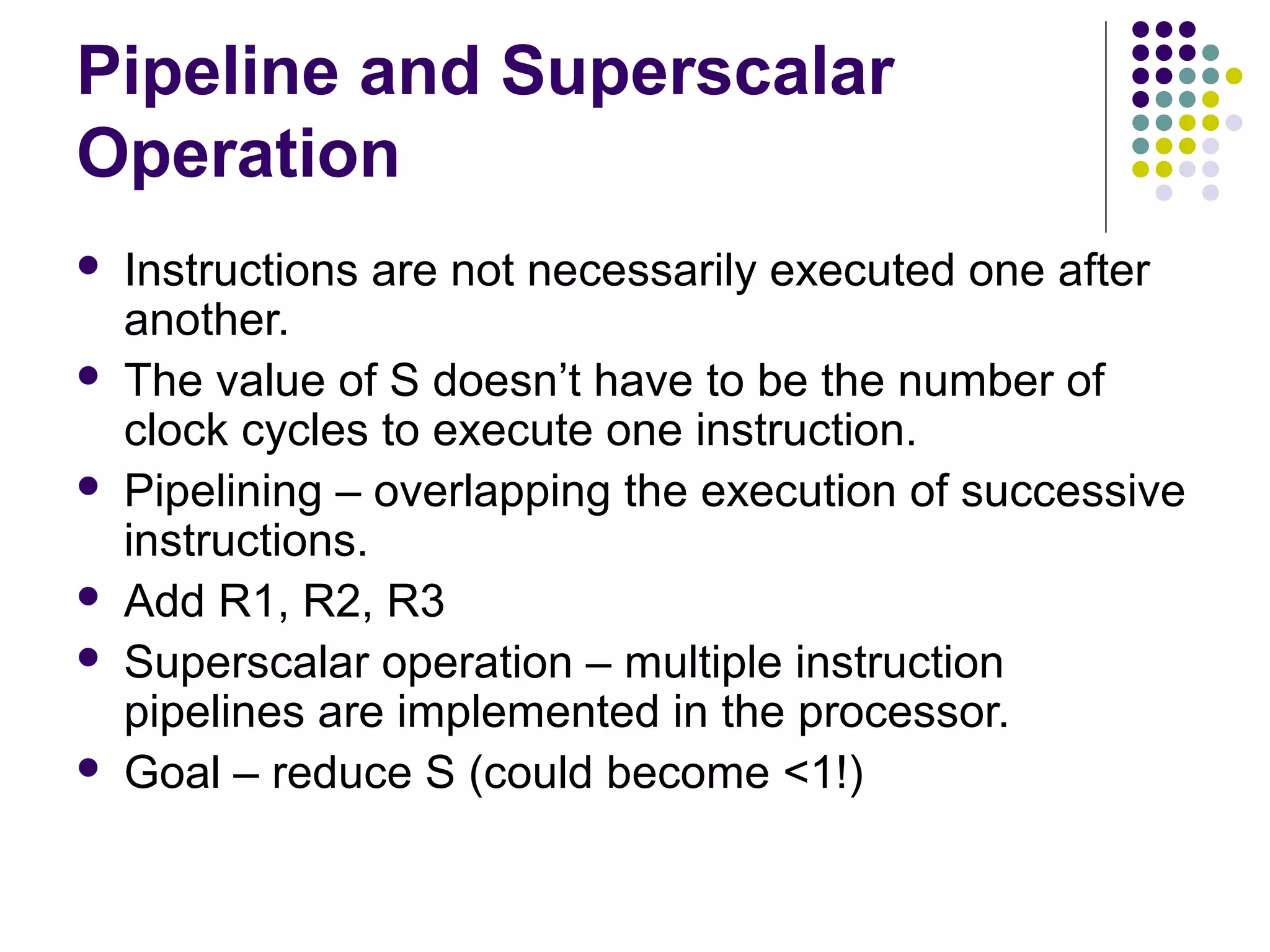
Introduction of basic performance equations and relationships affecting execution time and instruction sets.Role of compilers in optimizing instruction execution and methods for evaluating computer performance.
Distinction between multiprocessors for parallel tasks with shared memory and multicomputers with separate memory.


