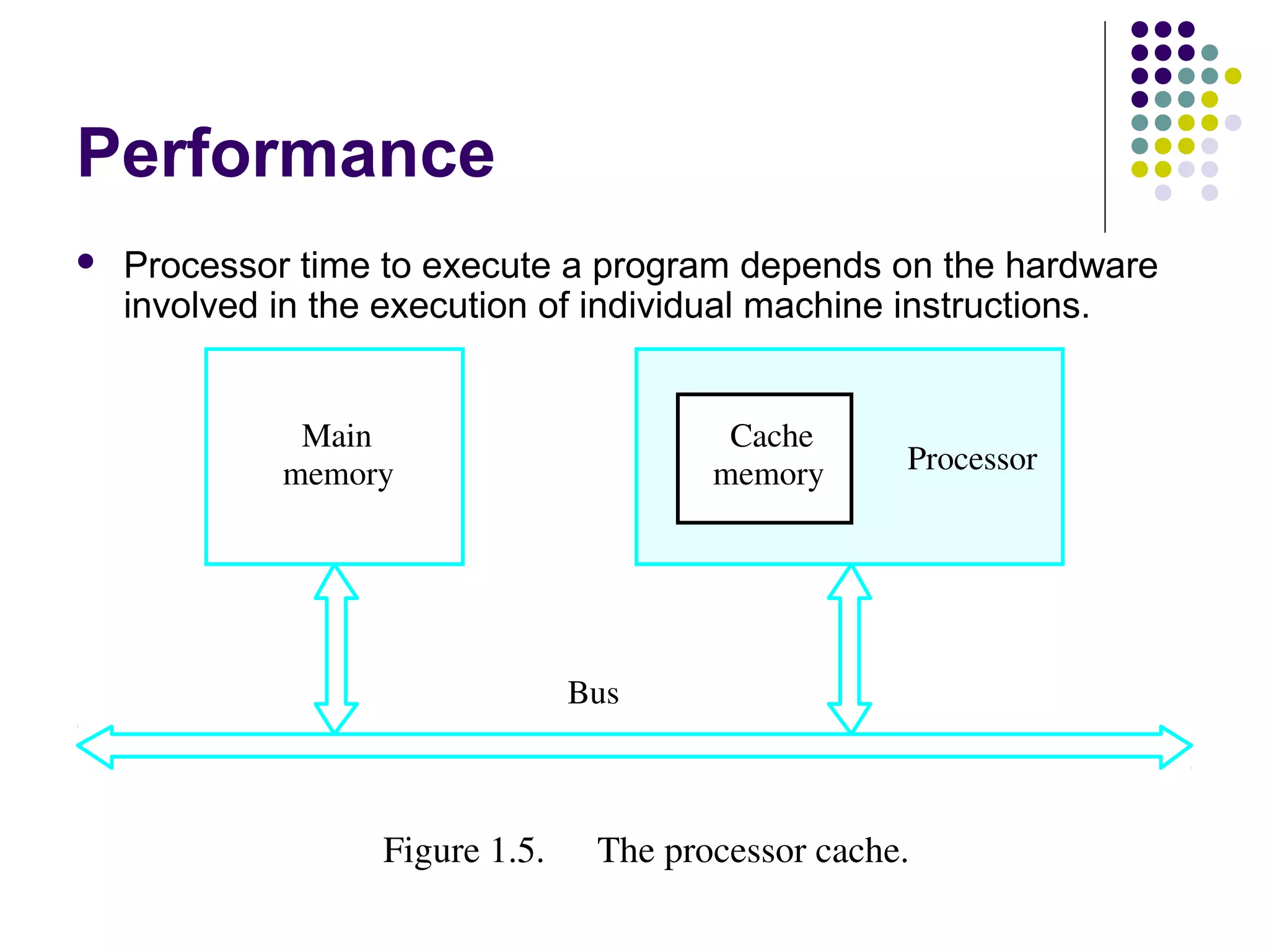
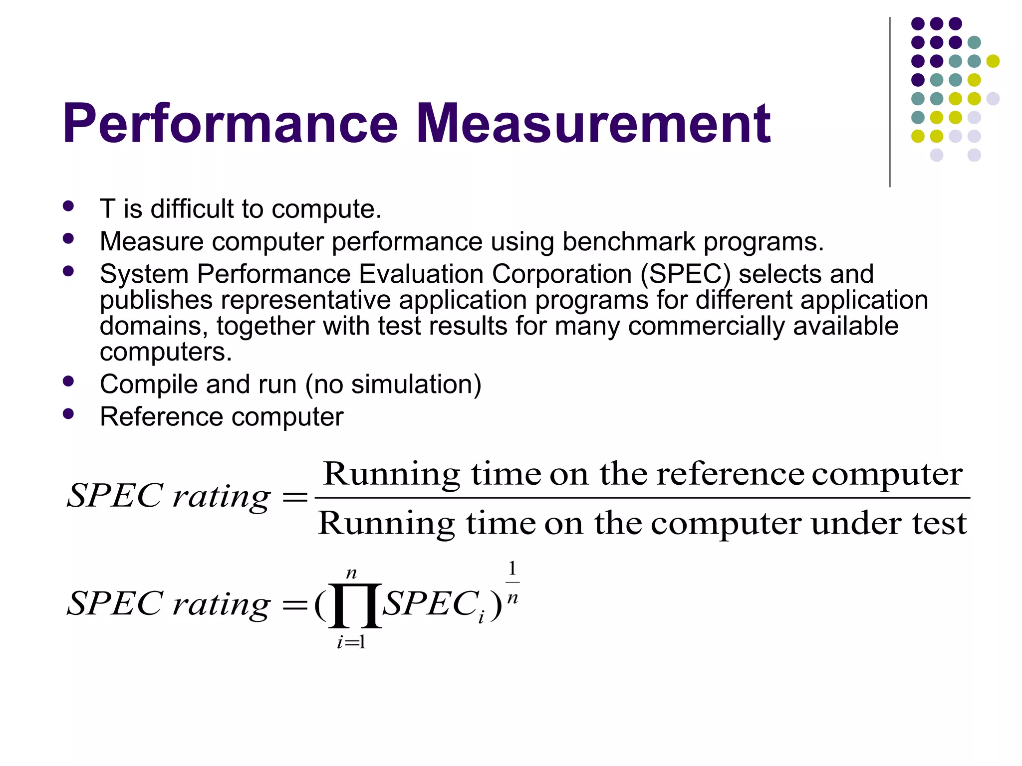
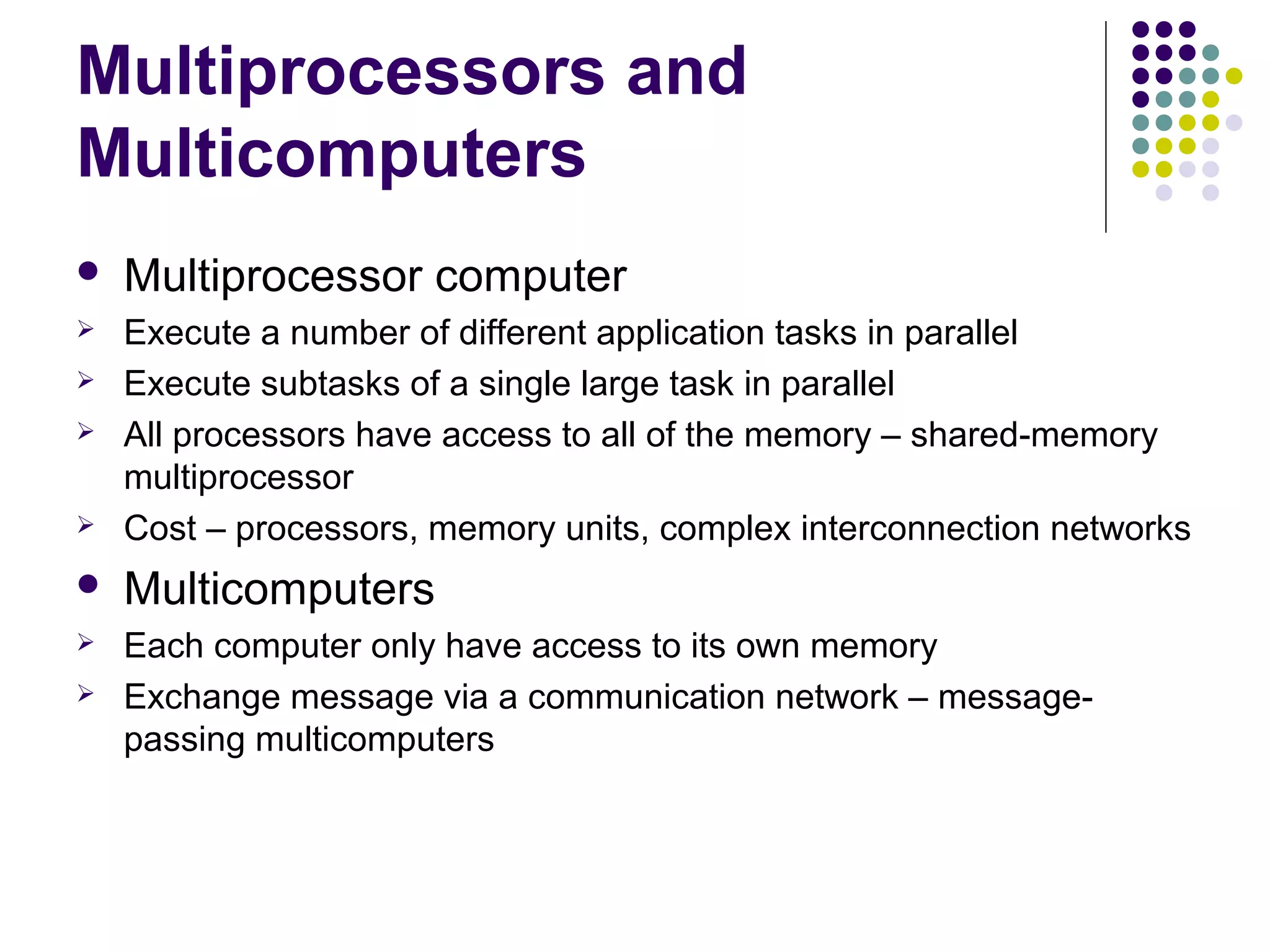
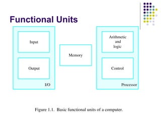
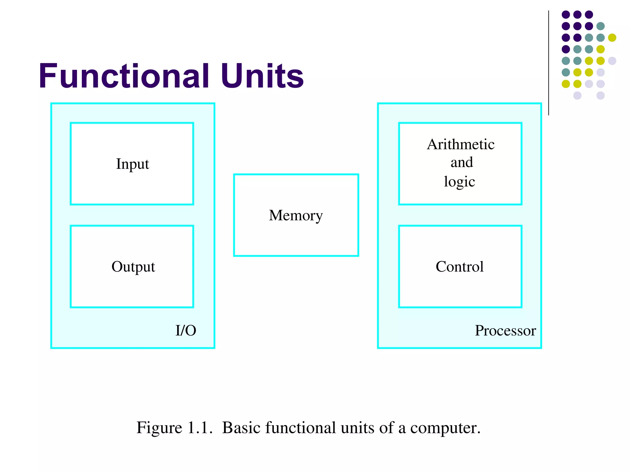
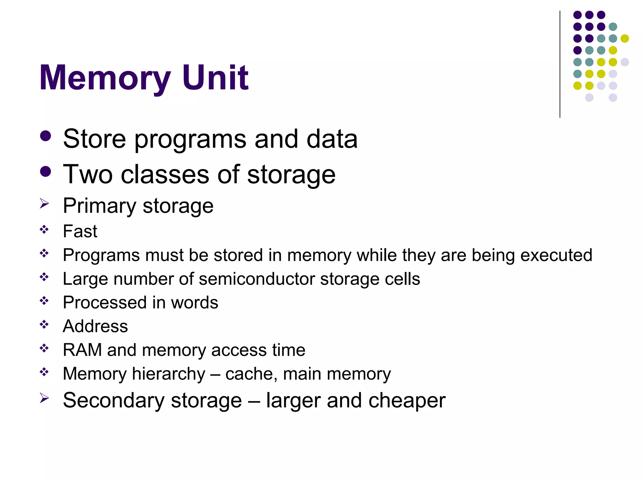
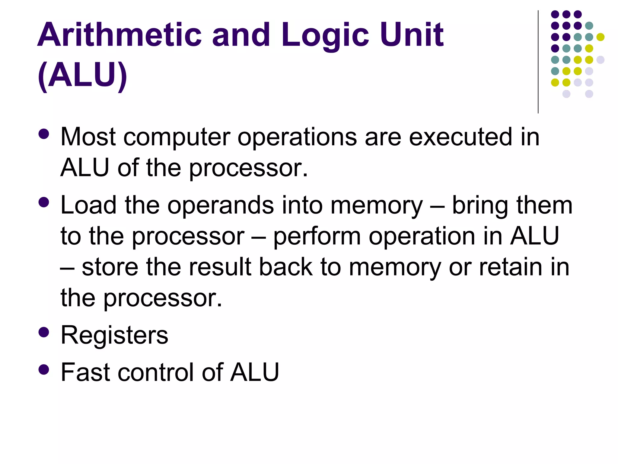
KEMBAR78
basic structure of computers | PPT
Chapter 1. Basic
Structure of Computers
Functional Units
Functional Units
                                                 Arithmetic
    Input                                            and
                                                   logic

                          Memory


    Output                                        Control


             I/O                                        Processor


       Figure 1.1.  Basic functional units of a computer.
Information Handled by a
Computer
 Instructions/machine         instructions
   Govern the transfer of information within a computer as
    well as between the computer and its I/O devices
   Specify the arithmetic and logic operations to be
    performed
   Program
 Data
   Used as operands by the instructions
   Source program
 Encoded       in binary code – 0 and 1
Memory Unit
 Storeprograms and data
 Two classes of storage
   Primary storage
   Fast
   Programs must be stored in memory while they are being executed
   Large number of semiconductor storage cells
   Processed in words
   Address
   RAM and memory access time
   Memory hierarchy – cache, main memory
   Secondary storage – larger and cheaper
Arithmetic and Logic Unit
(ALU)
 Most  computer operations are executed in
  ALU of the processor.
 Load the operands into memory – bring them
  to the processor – perform operation in ALU
  – store the result back to memory or retain in
  the processor.
 Registers

 Fast control of ALU
Control Unit
   All computer operations are controlled by the control
    unit.
   The timing signals that govern the I/O transfers are
    also generated by the control unit.
   Control unit is usually distributed throughout the
    machine instead of standing alone.
   Operations of a computer:
   Accept information in the form of programs and data through an
    input unit and store it in the memory
   Fetch the information stored in the memory, under program control,
    into an ALU, where the information is processed
   Output the processed information through an output unit
   Control all activities inside the machine through a control unit
The processor : Data Path and
Control


Two types of functional units:
   elements that operate on data values (combinational)
    elements that contain state (state elements)
Five Execution Steps
        Step name              Action for R-type         Action for Memory-        Action for    Action for
                                 instructions          reference Instructions      branches       jumps

     Instruction fetch                                          IR = MEM[PC]
                                                                 PC = PC + 4

Instruction decode/ register                                 A = Reg[IR[25-21]]
            fetch                                            B = Reg[IR[20-16]]
                                                   ALUOut = PC + (sign extend (IR[15-0])<<2)

   Execution, address          ALUOut = A op B           ALUOut = A+sign         IF(A==B) Then   PC=PC[31-
computation, branch/jump                                 extend(IR[15-0])         PC=ALUOut      28]||(IR[25-
      completion                                                                                   0]<<2)

 Memory access or R-type       Reg[IR[15-11]] =      Load:MDR =Mem[ALUOut]
      completion                  ALUOut                       or
                                                      Store:Mem[ALUOut] = B


 Memory read completion                                Load: Reg[IR[20-16]] =
                                                               MDR
Basic Operational
       Concepts
Review
   Activity in a computer is governed by instructions.
   To perform a task, an appropriate program
    consisting of a list of instructions is stored in the
    memory.
   Individual instructions are brought from the memory
    into the processor, which executes the specified
    operations.
   Data to be used as operands are also stored in the
    memory.
A Typical Instruction
   Add LOCA, R0
   Add the operand at memory location LOCA to the
    operand in a register R0 in the processor.
   Place the sum into register R0.
   The original contents of LOCA are preserved.
   The original contents of R0 is overwritten.
   Instruction is fetched from the memory into the
    processor – the operand at LOCA is fetched and
    added to the contents of R0 – the resulting sum is
    stored in register R0.
Separate Memory Access and
ALU Operation
 Load LOCA, R1
 Add R1, R0

 Whose contents will be overwritten?
Connection Between the
Processor and the Memory
                                 Memory


           MAR                    MDR
                                                        Control

            PC                     R0

                                   R1
                                                                        Processor
            IR


                                                         ALU
                                  Rn ­   1

                             n general purpose
                                 registers


     Figure 1.2.   Connections between the processor and the  memory.
Registers
 Instruction
            register (IR)
 Program counter (PC)

 General-purpose register (R – R )
                             0   n-1

 Memory address register (MAR)
 Memory data register (MDR)
Typical Operating Steps
 Programs   reside in the memory through input
  devices
 PC is set to point to the first instruction
 The contents of PC are transferred to MAR
 A Read signal is sent to the memory
 The first instruction is read out and loaded
  into MDR
 The contents of MDR are transferred to IR
 Decode and execute the instruction
Typical Operating Steps
(Cont’)
 Get   operands for ALU
    General-purpose register
    Memory (address to MAR – Read – MDR to ALU)
 Perform  operation in ALU
 Store the result back
    To general-purpose register
    To memory (address to MAR, result to MDR – Write)
 During
       the execution, PC is
 incremented to the next instruction
Interrupt
   Normal execution of programs may be preempted if
    some device requires urgent servicing.
   The normal execution of the current program must
    be interrupted – the device raises an interrupt
    signal.
   Interrupt-service routine
   Current system information backup and restore (PC,
    general-purpose registers, control information,
    specific information)
Bus Structures
 There  are many ways to connect different
  parts inside a computer together.
 A group of lines that serves as a connecting
  path for several devices is called a bus.
 Address/data/control
Bus Structure
 Single-bus


      Input         Output              Memory        Processor


               Figure 1.3.    Single­bus structure.
Speed Issue
 Different devices have different
  transfer/operate speed.
 If the speed of bus is bounded by the slowest
  device connected to it, the efficiency will be
  very low.
 How to solve this?

 A common approach – use buffers.
Performance
Performance
 The most important measure of a computer is
  how quickly it can execute programs.
 Three factors affect performance:
   Hardware design
   Instruction set
   Compiler
Performance
   Processor time to execute a program depends on the hardware
    involved in the execution of individual machine instructions.


              Main                        Cache
             memory                      memory      Processor


                                 Bus


                   Figure 1.5.    The processor cache.
Performance
 The  processor and a relatively small cache
  memory can be fabricated on a single
  integrated circuit chip.
 Speed

 Cost

 Memory management
Processor Clock
 Clock, clock cycle, and clock rate
 The execution of each instruction is divided
  into several steps, each of which completes
  in one clock cycle.
 Hertz – cycles per second
Basic Performance Equation
   T – processor time required to execute a program that has been
    prepared in high-level language
   N – number of actual machine language instructions needed to
    complete the execution (note: loop)
   S – average number of basic steps needed to execute one
    machine instruction. Each step completes in one clock cycle
   R – clock rate
   Note: these are not independent to each other

                              N×S
                           T=
                               R
       How to improve T?
Pipeline and Superscalar
Operation
   Instructions are not necessarily executed one after
    another.
   The value of S doesn’t have to be the number of
    clock cycles to execute one instruction.
   Pipelining – overlapping the execution of successive
    instructions.
   Add R1, R2, R3
   Superscalar operation – multiple instruction
    pipelines are implemented in the processor.
   Goal – reduce S (could become <1!)
Clock Rate
 Increase    clock rate
   Improve the integrated-circuit (IC) technology to make
    the circuits faster
   Reduce the amount of processing done in one basic step
    (however, this may increase the number of basic steps
    needed)
 Increases   in R that are entirely caused by
    improvements in IC technology affect all
    aspects of the processor’s operation equally
    except the time to access the main memory.
CISC and RISC
 Tradeoffbetween N and S
 A key consideration is the use of pipelining
   S is close to 1 even though the number of basic steps
    per instruction may be considerably larger
   It is much easier to implement efficient pipelining in
    processor with simple instruction sets
 Reduced Instruction Set Computers (RISC)
 Complex Instruction Set Computers (CISC)
Compiler
   A compiler translates a high-level language program
    into a sequence of machine instructions.
   To reduce N, we need a suitable machine
    instruction set and a compiler that makes good use
    of it.
   Goal – reduce N×S
   A compiler may not be designed for a specific
    processor; however, a high-quality compiler is
    usually designed for, and with, a specific processor.
Performance Measurement
   T is difficult to compute.
   Measure computer performance using benchmark programs.
   System Performance Evaluation Corporation (SPEC) selects and
    publishes representative application programs for different application
    domains, together with test results for many commercially available
    computers.
   Compile and run (no simulation)
   Reference computer

              Running time on the reference computer
SPEC rating =
              Running time on the computer under test
                         n            1
SPEC rating = (∏SPECi )               n

                        i =1
Multiprocessors and
Multicomputers
   Multiprocessor computer
   Execute a number of different application tasks in parallel
   Execute subtasks of a single large task in parallel
   All processors have access to all of the memory – shared-memory
    multiprocessor
   Cost – processors, memory units, complex interconnection networks
   Multicomputers
   Each computer only have access to its own memory
   Exchange message via a communication network – message-
    passing multicomputers

basic structure of computers

  • 1.
  • 2.
  • 3.
    Functional Units Arithmetic Input and logic Memory Output Control I/O Processor Figure 1.1.  Basic functional units of a computer.
  • 4.
    Information Handled bya Computer  Instructions/machine instructions  Govern the transfer of information within a computer as well as between the computer and its I/O devices  Specify the arithmetic and logic operations to be performed  Program  Data  Used as operands by the instructions  Source program  Encoded in binary code – 0 and 1
  • 5.
    Memory Unit  Storeprogramsand data  Two classes of storage  Primary storage  Fast  Programs must be stored in memory while they are being executed  Large number of semiconductor storage cells  Processed in words  Address  RAM and memory access time  Memory hierarchy – cache, main memory  Secondary storage – larger and cheaper
  • 6.
    Arithmetic and LogicUnit (ALU)  Most computer operations are executed in ALU of the processor.  Load the operands into memory – bring them to the processor – perform operation in ALU – store the result back to memory or retain in the processor.  Registers  Fast control of ALU
  • 7.
    Control Unit  All computer operations are controlled by the control unit.  The timing signals that govern the I/O transfers are also generated by the control unit.  Control unit is usually distributed throughout the machine instead of standing alone.  Operations of a computer:  Accept information in the form of programs and data through an input unit and store it in the memory  Fetch the information stored in the memory, under program control, into an ALU, where the information is processed  Output the processed information through an output unit  Control all activities inside the machine through a control unit
  • 8.
    The processor :Data Path and Control Two types of functional units: elements that operate on data values (combinational)  elements that contain state (state elements)
  • 9.
    Five Execution Steps Step name Action for R-type Action for Memory- Action for Action for instructions reference Instructions branches jumps Instruction fetch IR = MEM[PC] PC = PC + 4 Instruction decode/ register A = Reg[IR[25-21]] fetch B = Reg[IR[20-16]] ALUOut = PC + (sign extend (IR[15-0])<<2) Execution, address ALUOut = A op B ALUOut = A+sign IF(A==B) Then PC=PC[31- computation, branch/jump extend(IR[15-0]) PC=ALUOut 28]||(IR[25- completion 0]<<2) Memory access or R-type Reg[IR[15-11]] = Load:MDR =Mem[ALUOut] completion ALUOut or Store:Mem[ALUOut] = B Memory read completion Load: Reg[IR[20-16]] = MDR
  • 10.
  • 11.
    Review  Activity in a computer is governed by instructions.  To perform a task, an appropriate program consisting of a list of instructions is stored in the memory.  Individual instructions are brought from the memory into the processor, which executes the specified operations.  Data to be used as operands are also stored in the memory.
  • 12.
    A Typical Instruction  Add LOCA, R0  Add the operand at memory location LOCA to the operand in a register R0 in the processor.  Place the sum into register R0.  The original contents of LOCA are preserved.  The original contents of R0 is overwritten.  Instruction is fetched from the memory into the processor – the operand at LOCA is fetched and added to the contents of R0 – the resulting sum is stored in register R0.
  • 13.
    Separate Memory Accessand ALU Operation  Load LOCA, R1  Add R1, R0  Whose contents will be overwritten?
  • 14.
    Connection Between the Processorand the Memory Memory MAR MDR Control PC R0 R1 Processor IR ALU Rn ­ 1 n general purpose registers Figure 1.2.   Connections between the processor and the  memory.
  • 15.
    Registers  Instruction register (IR)  Program counter (PC)  General-purpose register (R – R ) 0 n-1  Memory address register (MAR)  Memory data register (MDR)
  • 16.
    Typical Operating Steps Programs reside in the memory through input devices  PC is set to point to the first instruction  The contents of PC are transferred to MAR  A Read signal is sent to the memory  The first instruction is read out and loaded into MDR  The contents of MDR are transferred to IR  Decode and execute the instruction
  • 17.
    Typical Operating Steps (Cont’) Get operands for ALU  General-purpose register  Memory (address to MAR – Read – MDR to ALU)  Perform operation in ALU  Store the result back  To general-purpose register  To memory (address to MAR, result to MDR – Write)  During the execution, PC is incremented to the next instruction
  • 18.
    Interrupt  Normal execution of programs may be preempted if some device requires urgent servicing.  The normal execution of the current program must be interrupted – the device raises an interrupt signal.  Interrupt-service routine  Current system information backup and restore (PC, general-purpose registers, control information, specific information)
  • 19.
    Bus Structures  There are many ways to connect different parts inside a computer together.  A group of lines that serves as a connecting path for several devices is called a bus.  Address/data/control
  • 20.
    Bus Structure  Single-bus Input Output Memory Processor Figure 1.3.    Single­bus structure.
  • 21.
    Speed Issue  Differentdevices have different transfer/operate speed.  If the speed of bus is bounded by the slowest device connected to it, the efficiency will be very low.  How to solve this?  A common approach – use buffers.
  • 22.
  • 23.
    Performance  The mostimportant measure of a computer is how quickly it can execute programs.  Three factors affect performance:  Hardware design  Instruction set  Compiler
  • 24.
    Performance  Processor time to execute a program depends on the hardware involved in the execution of individual machine instructions. Main Cache memory memory Processor Bus Figure 1.5. The processor cache.
  • 25.
    Performance  The processor and a relatively small cache memory can be fabricated on a single integrated circuit chip.  Speed  Cost  Memory management
  • 26.
    Processor Clock  Clock,clock cycle, and clock rate  The execution of each instruction is divided into several steps, each of which completes in one clock cycle.  Hertz – cycles per second
  • 27.
    Basic Performance Equation  T – processor time required to execute a program that has been prepared in high-level language  N – number of actual machine language instructions needed to complete the execution (note: loop)  S – average number of basic steps needed to execute one machine instruction. Each step completes in one clock cycle  R – clock rate  Note: these are not independent to each other N×S T= R How to improve T?
  • 28.
    Pipeline and Superscalar Operation  Instructions are not necessarily executed one after another.  The value of S doesn’t have to be the number of clock cycles to execute one instruction.  Pipelining – overlapping the execution of successive instructions.  Add R1, R2, R3  Superscalar operation – multiple instruction pipelines are implemented in the processor.  Goal – reduce S (could become <1!)
  • 29.
    Clock Rate  Increase clock rate  Improve the integrated-circuit (IC) technology to make the circuits faster  Reduce the amount of processing done in one basic step (however, this may increase the number of basic steps needed)  Increases in R that are entirely caused by improvements in IC technology affect all aspects of the processor’s operation equally except the time to access the main memory.
  • 30.
    CISC and RISC Tradeoffbetween N and S  A key consideration is the use of pipelining  S is close to 1 even though the number of basic steps per instruction may be considerably larger  It is much easier to implement efficient pipelining in processor with simple instruction sets  Reduced Instruction Set Computers (RISC)  Complex Instruction Set Computers (CISC)
  • 31.
    Compiler  A compiler translates a high-level language program into a sequence of machine instructions.  To reduce N, we need a suitable machine instruction set and a compiler that makes good use of it.  Goal – reduce N×S  A compiler may not be designed for a specific processor; however, a high-quality compiler is usually designed for, and with, a specific processor.
  • 32.
    Performance Measurement  T is difficult to compute.  Measure computer performance using benchmark programs.  System Performance Evaluation Corporation (SPEC) selects and publishes representative application programs for different application domains, together with test results for many commercially available computers.  Compile and run (no simulation)  Reference computer Running time on the reference computer SPEC rating = Running time on the computer under test n 1 SPEC rating = (∏SPECi ) n i =1
  • 33.
    Multiprocessors and Multicomputers  Multiprocessor computer  Execute a number of different application tasks in parallel  Execute subtasks of a single large task in parallel  All processors have access to all of the memory – shared-memory multiprocessor  Cost – processors, memory units, complex interconnection networks  Multicomputers  Each computer only have access to its own memory  Exchange message via a communication network – message- passing multicomputers