Downloaded 1,825 times
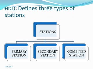
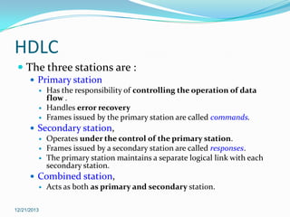
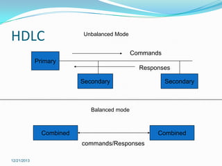
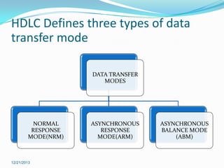
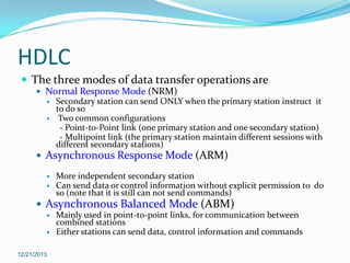

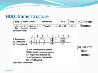


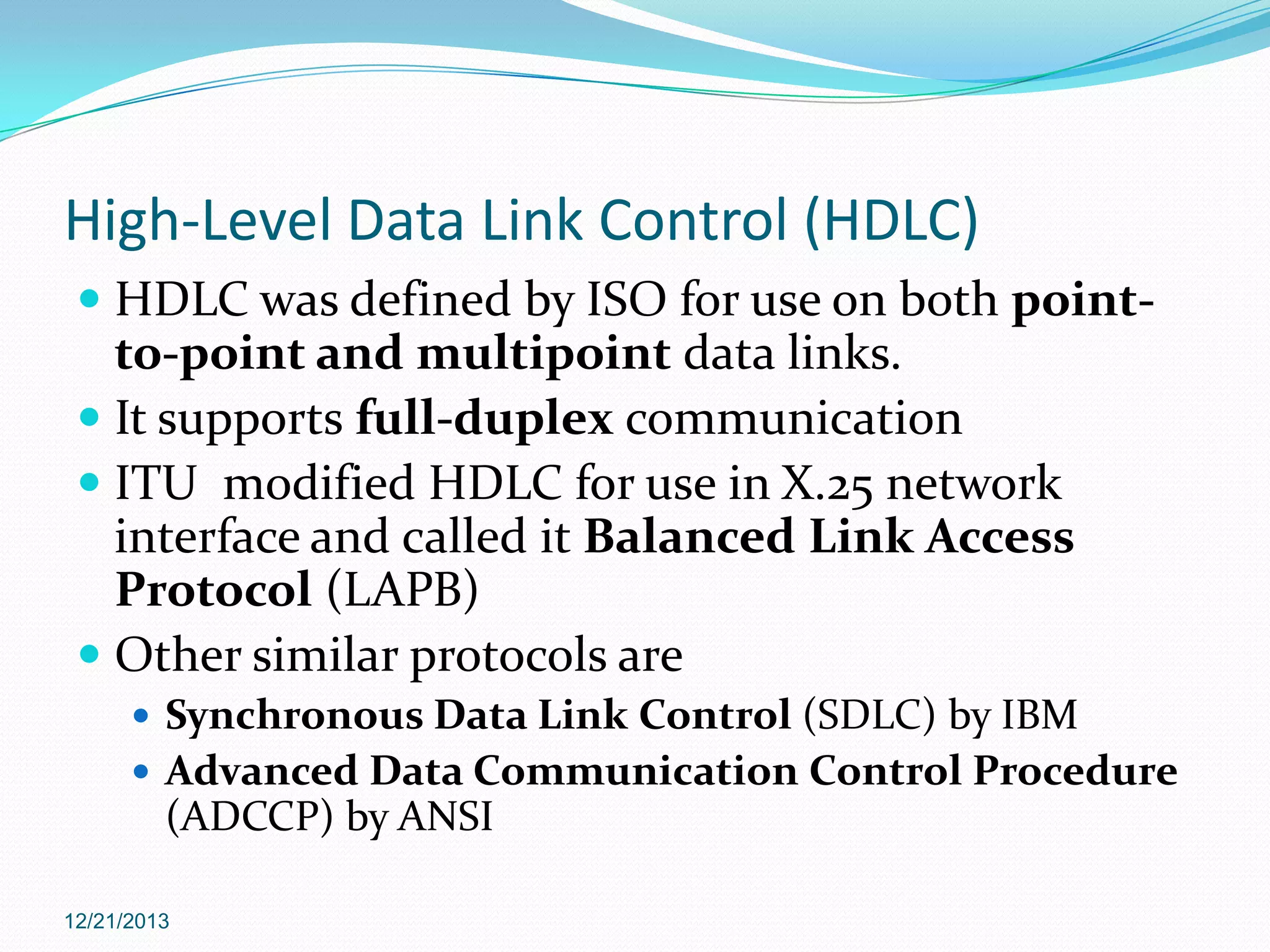
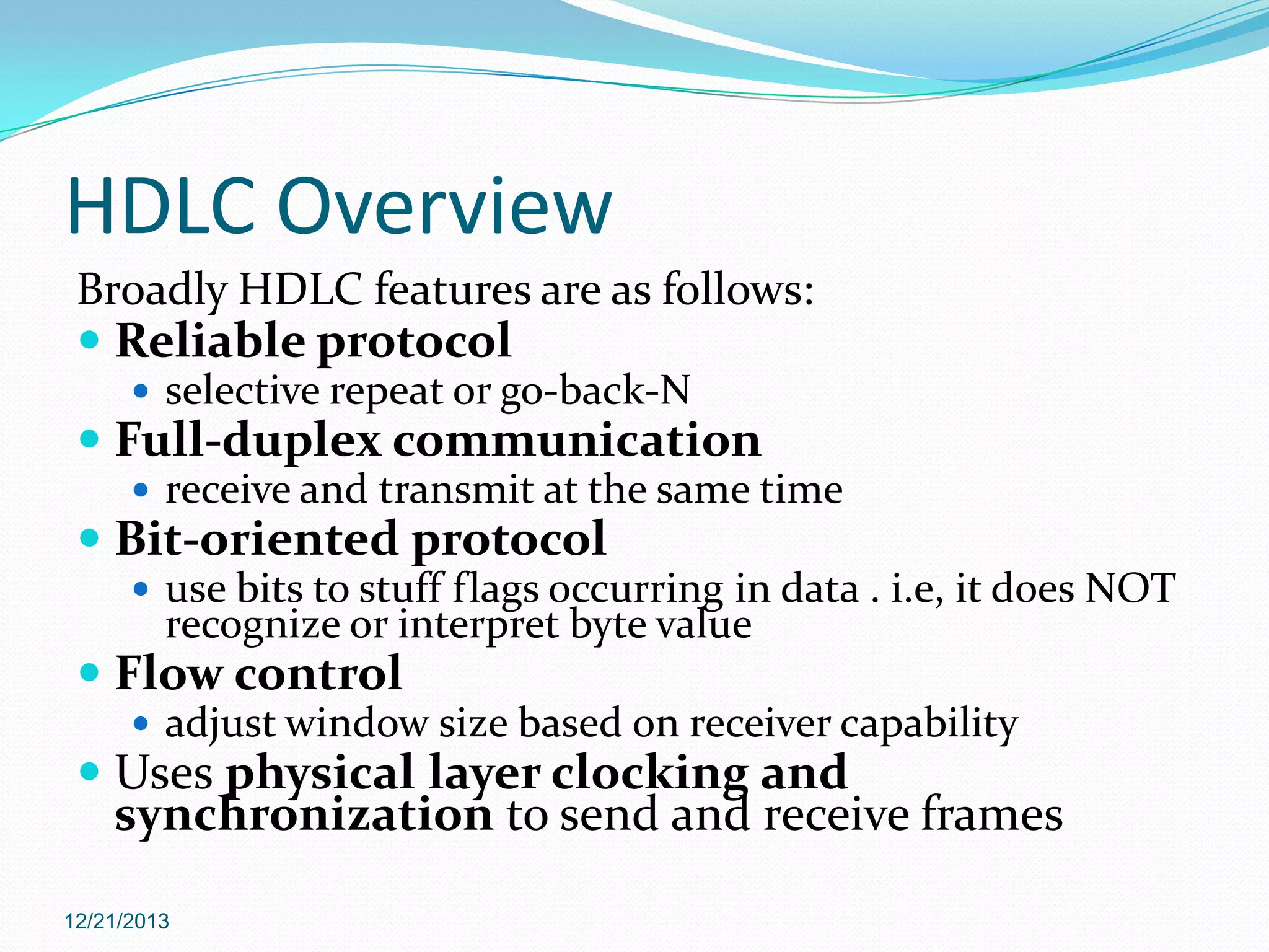
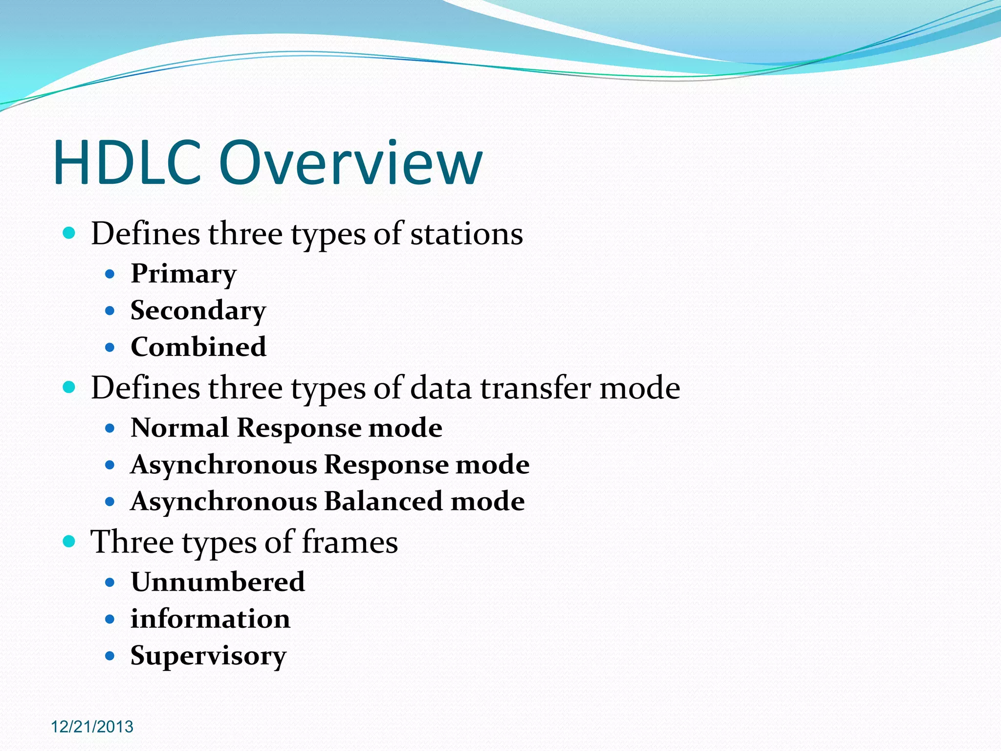


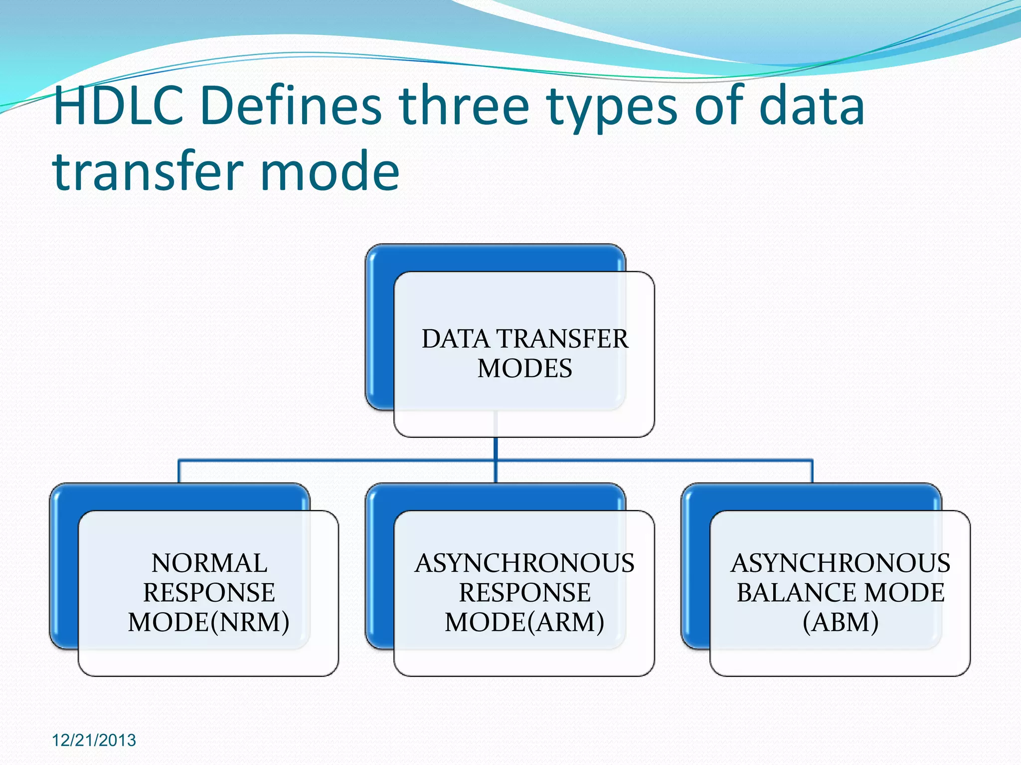

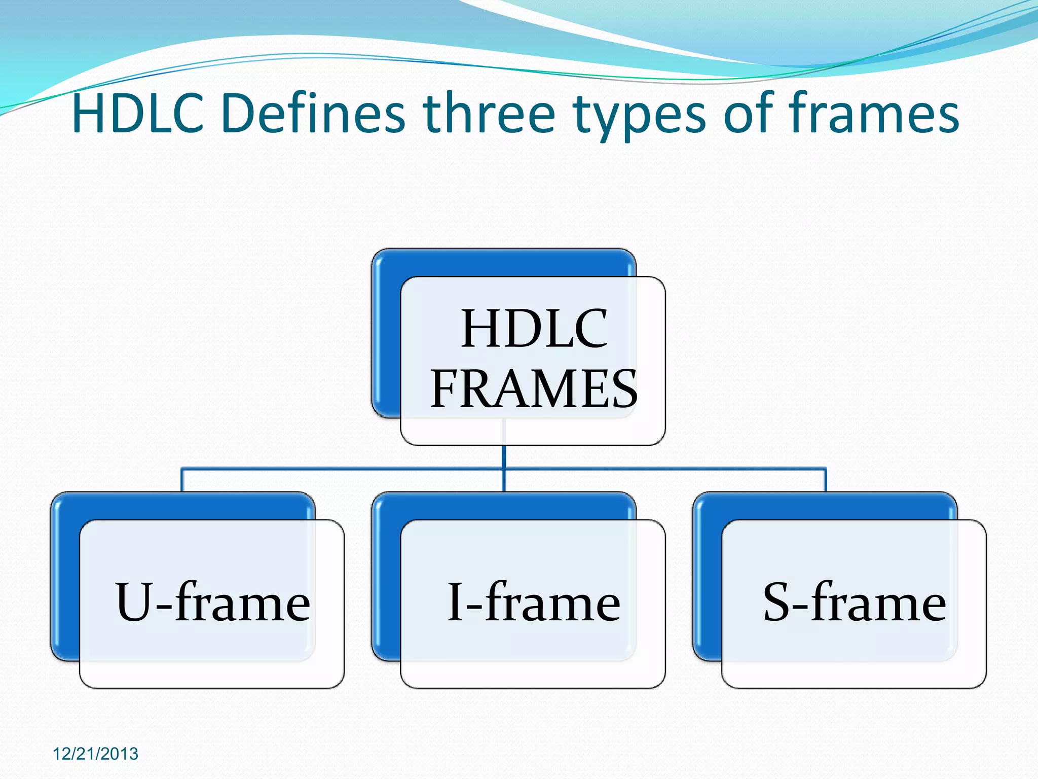
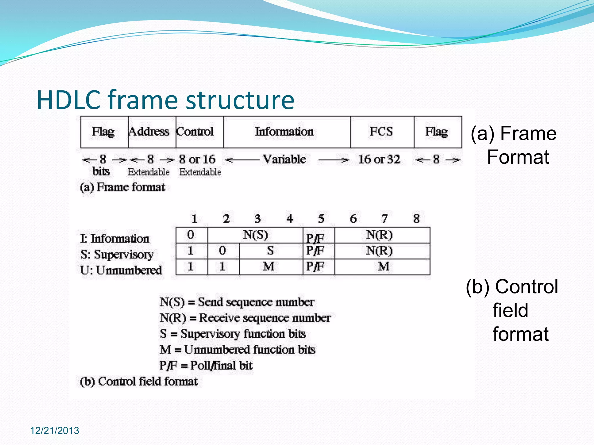

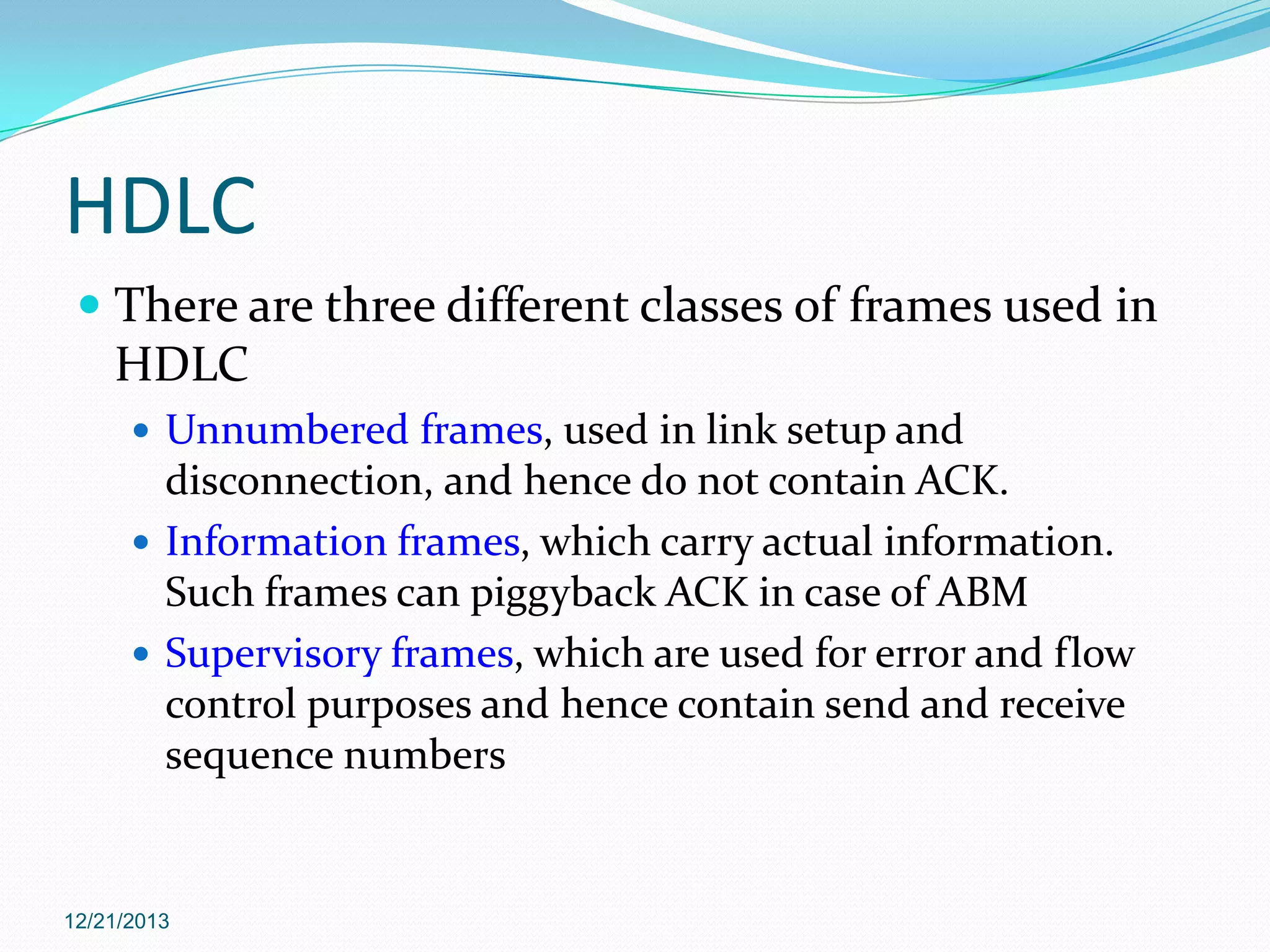


The document describes High-Level Data Link Control (HDLC), a bit-oriented protocol developed by ISO for point-to-point and multipoint data links. HDLC supports full-duplex communication and was modified by ITU as Balanced Link Access Protocol for use in X.25 networks. It defines three types of stations (primary, secondary, combined), three modes of data transfer (normal response, asynchronous response, asynchronous balanced), and three types of frames (unnumbered, information, supervisory). HDLC provides reliable communication, flow control, and uses physical layer synchronization.


