Downloaded 65 times


![Dotted Decimal Notation
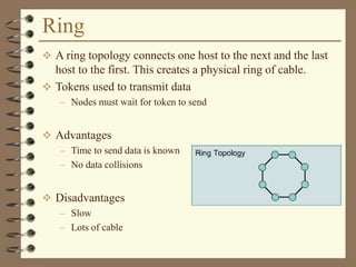
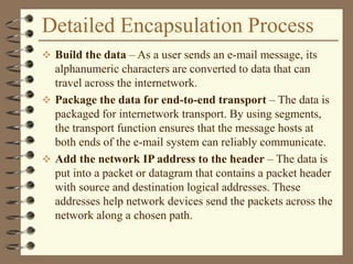
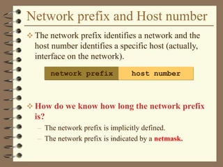
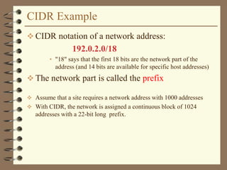
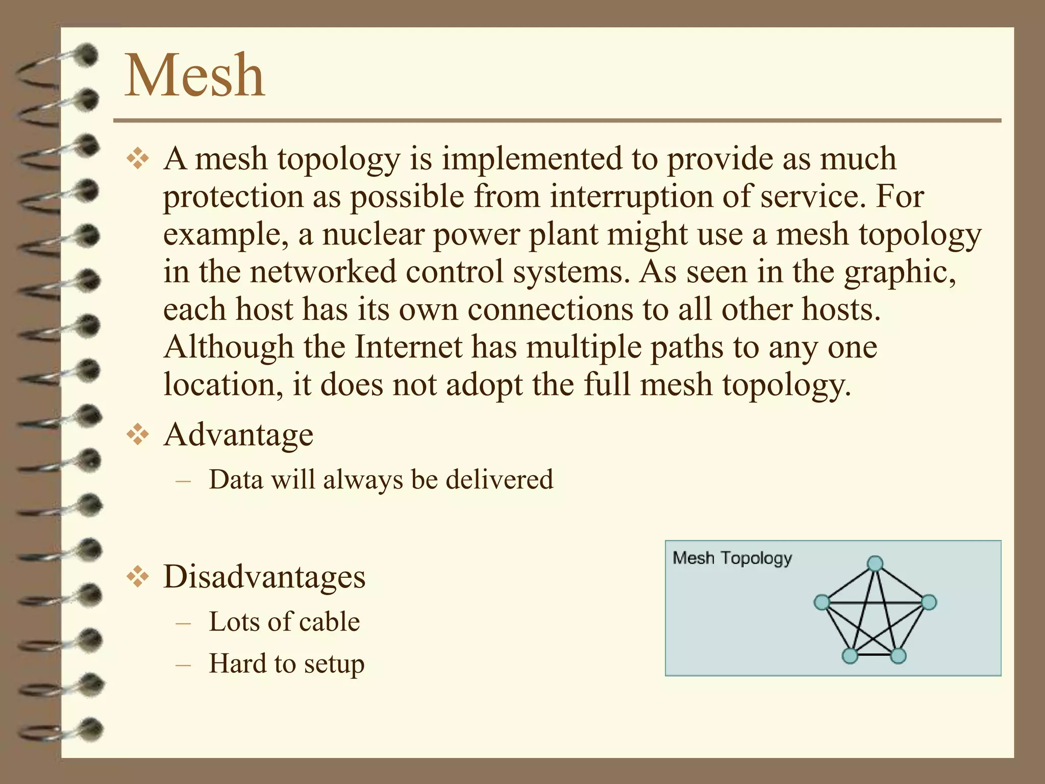
IP addresses are written in a so-called dotted
decimal notation
Each byte is identified by a decimal number in the
range [0..255]:
Example:
1000111110000000 10001001 10010000
1st Byte
= 128
2nd
Byte
= 143
3rd Byte
= 137
4th Byte
= 144
128.143.137.144](https://image.slidesharecdn.com/introductiontocomputernetwork-170621080423/85/Introduction-to-computer-network-134-320.jpg)
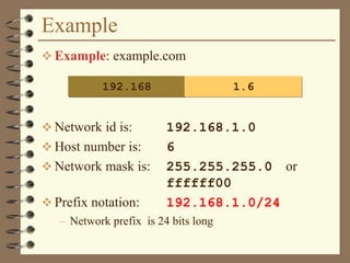

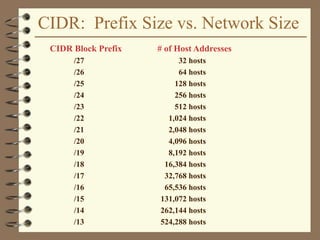
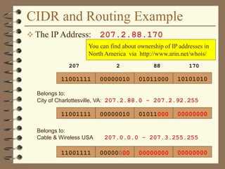


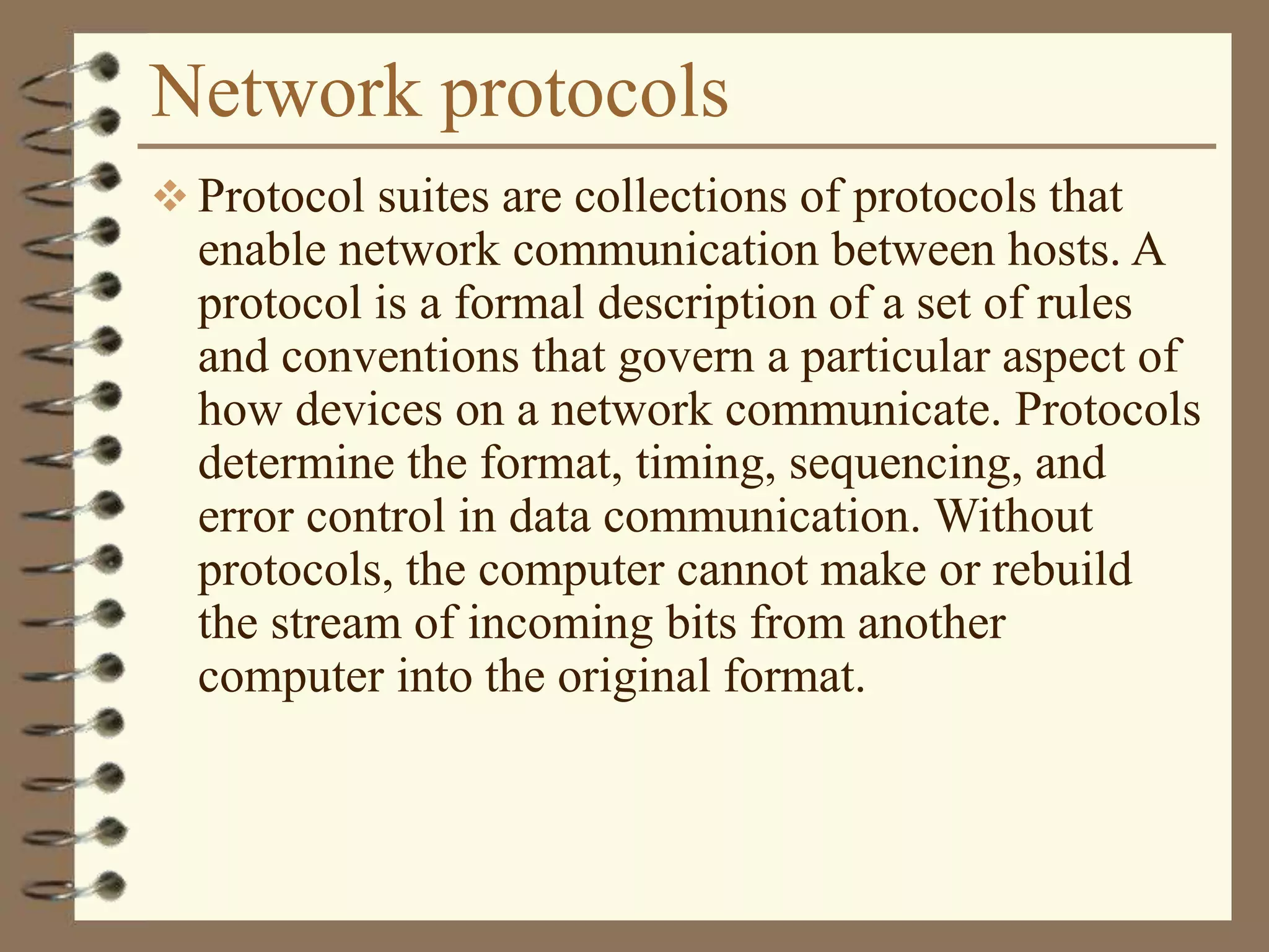


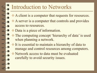
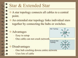
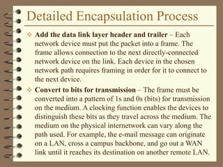
![Dotted Decimal Notation
IP addresses are written in a so-called dotted
decimal notation
Each byte is identified by a decimal number in the
range [0..255]:
Example:
1000111110000000 10001001 10010000
1st Byte
= 128
2nd
Byte
= 143
3rd Byte
= 137
4th Byte
= 144
128.143.137.144](https://image.slidesharecdn.com/introductiontocomputernetwork-170621080423/75/Introduction-to-computer-network-134-2048.jpg)


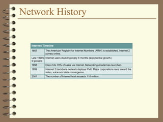
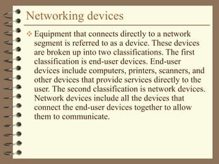
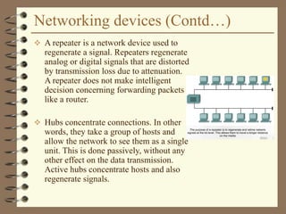
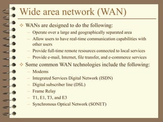
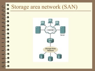
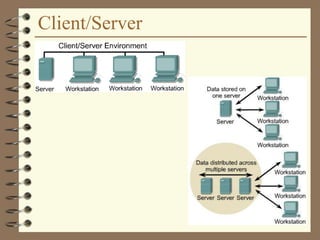
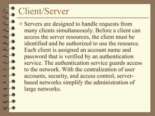
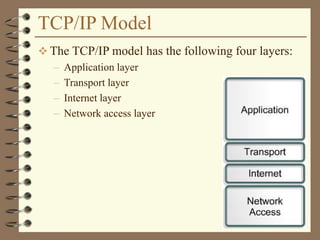
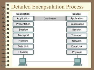
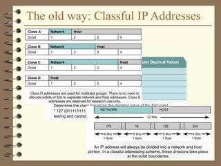
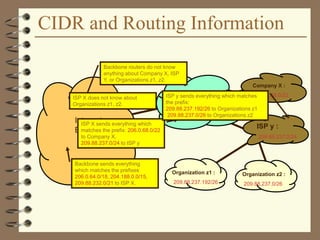
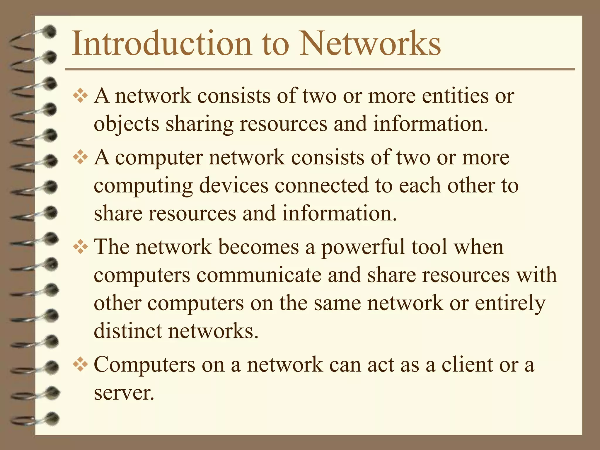
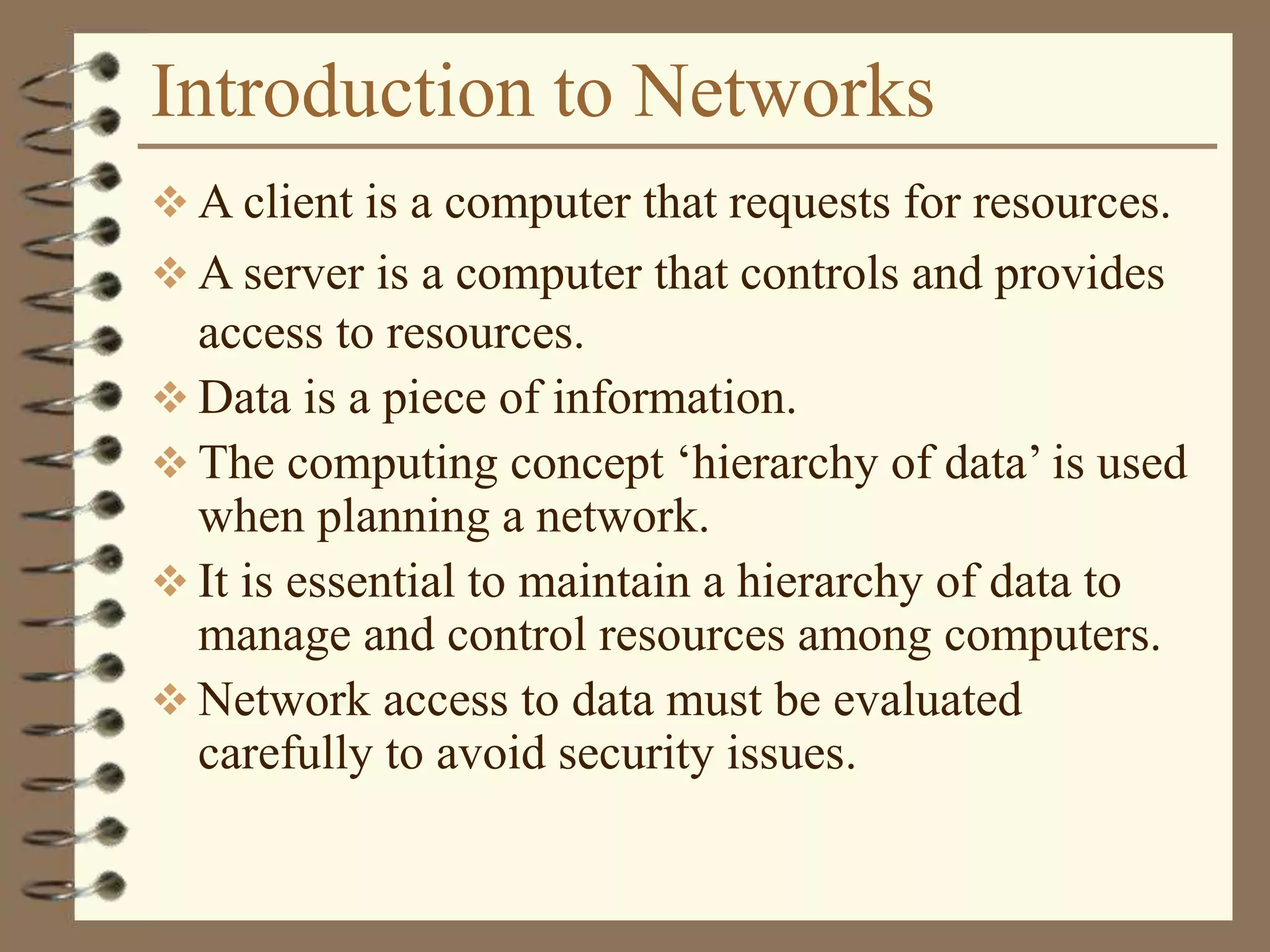
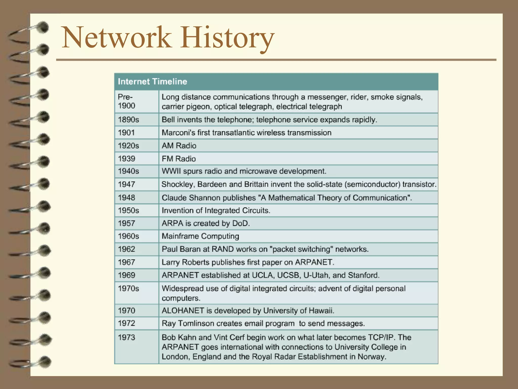
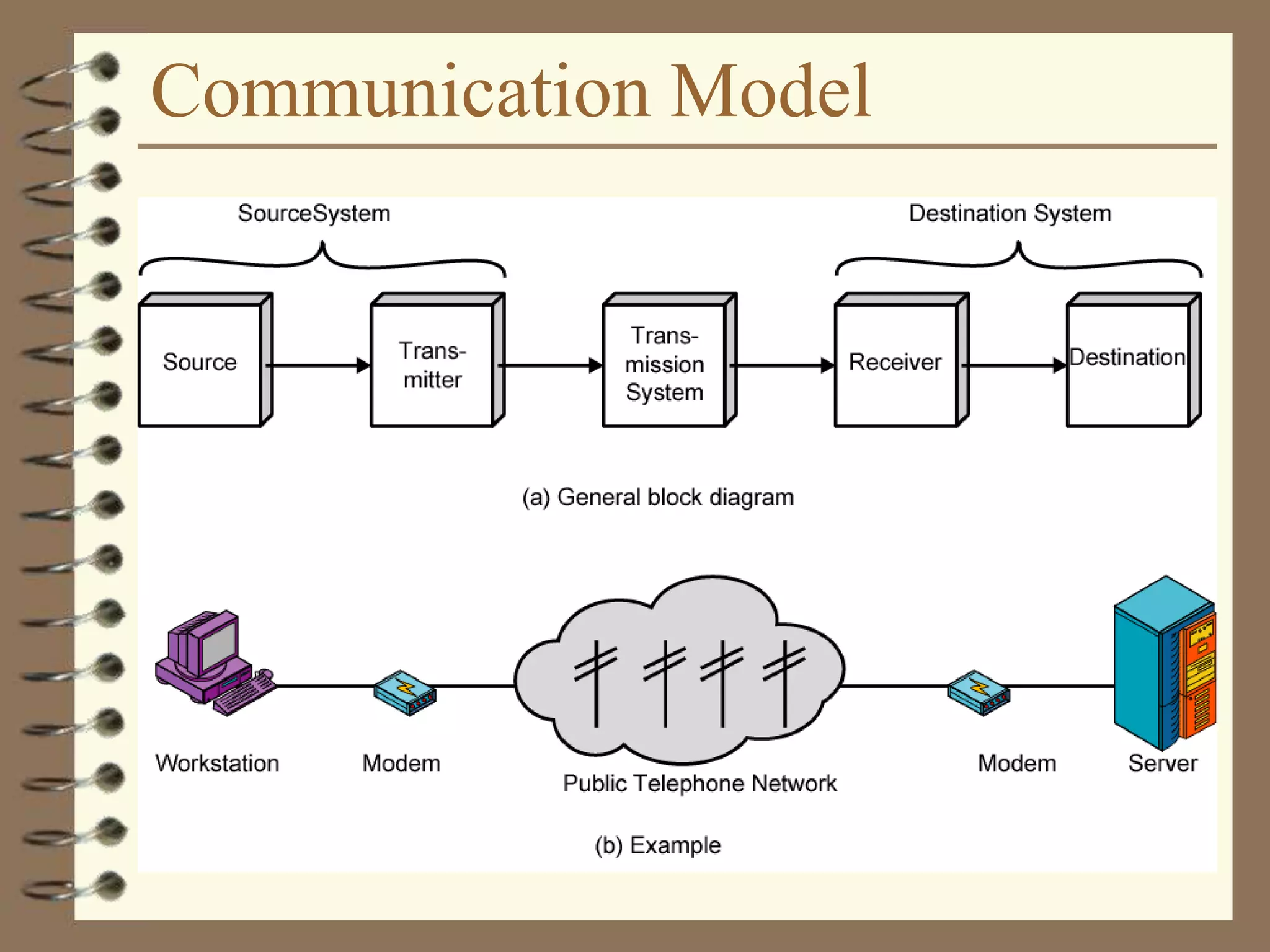
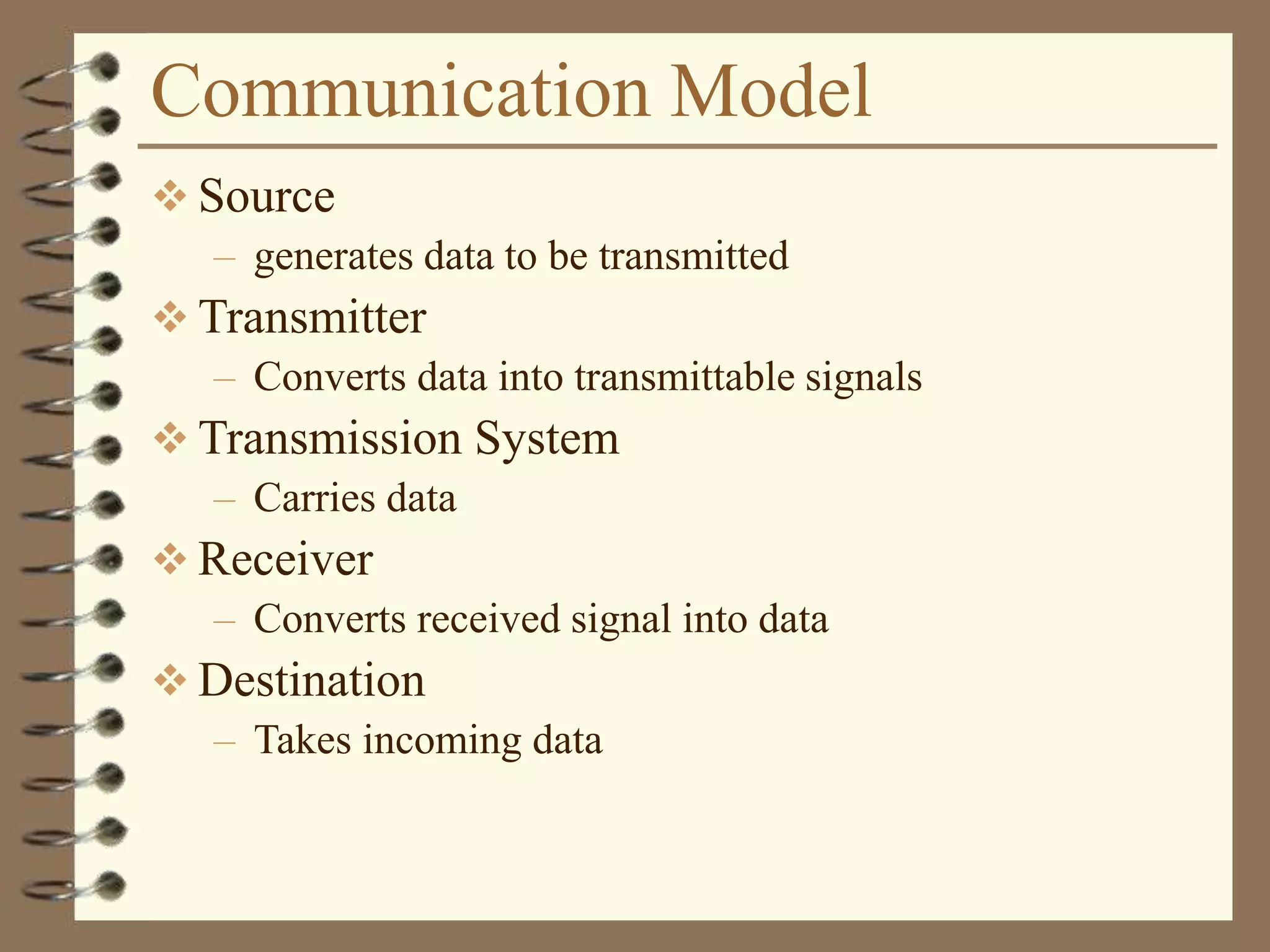
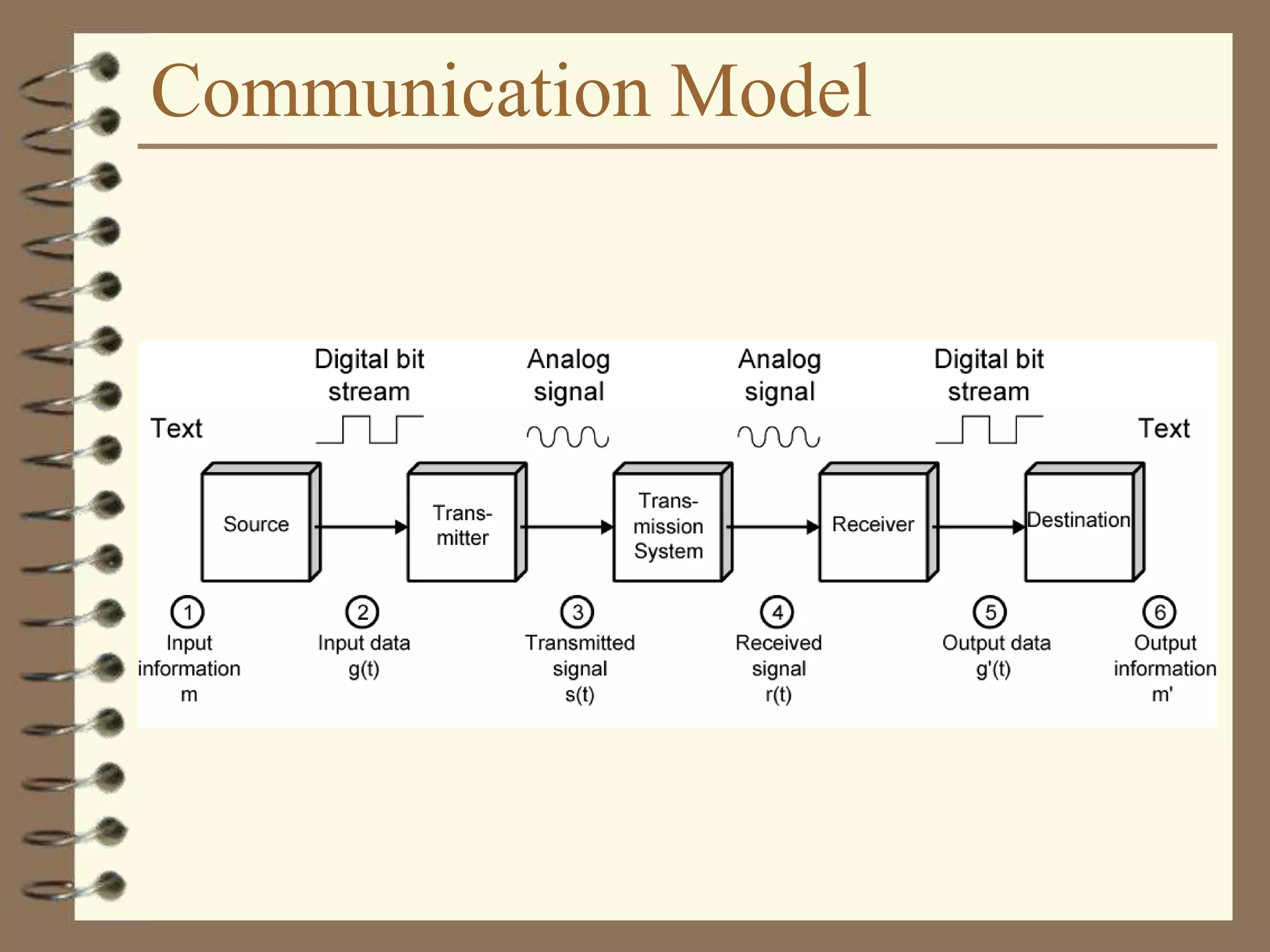
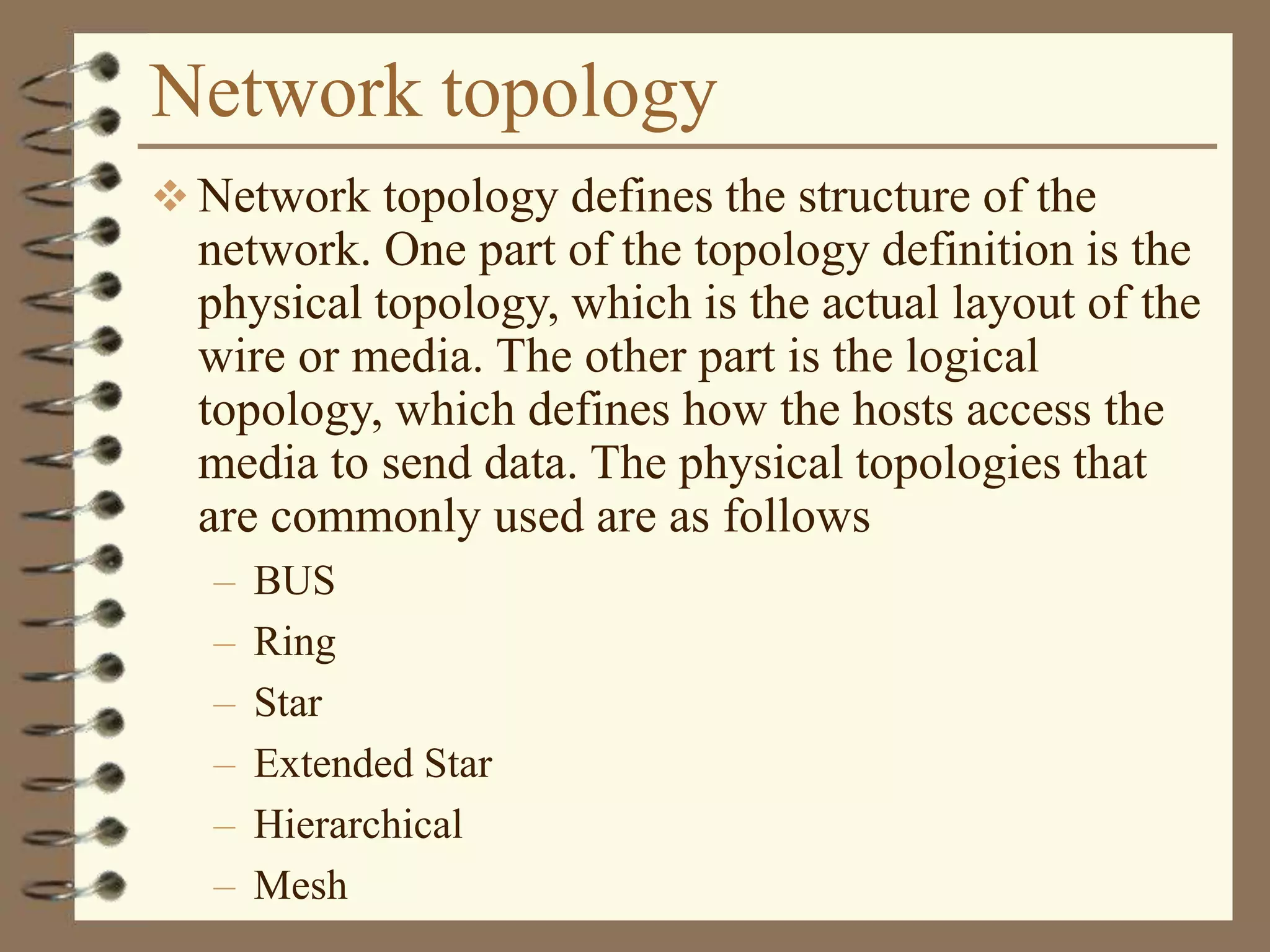
The document provides an overview of computer networks, including definitions, the communication model, and types of networks such as LANs, WANs, and SANs. It discusses the roles of clients and servers, advantages and disadvantages of peer-to-peer versus client/server networks, networking devices, topologies, protocols, and models. The information serves as an introductory guide for understanding the key concepts and components involved in networking.


![UiPath Automation Suite Installation (Hands-On) [2/3]](https://cdn.slidesharecdn.com/ss_thumbnails/automationsuitecommunitysession2-251015095633-a6d862f1-thumbnail.jpg?width=600ounds&width=560&fit=bounds)


