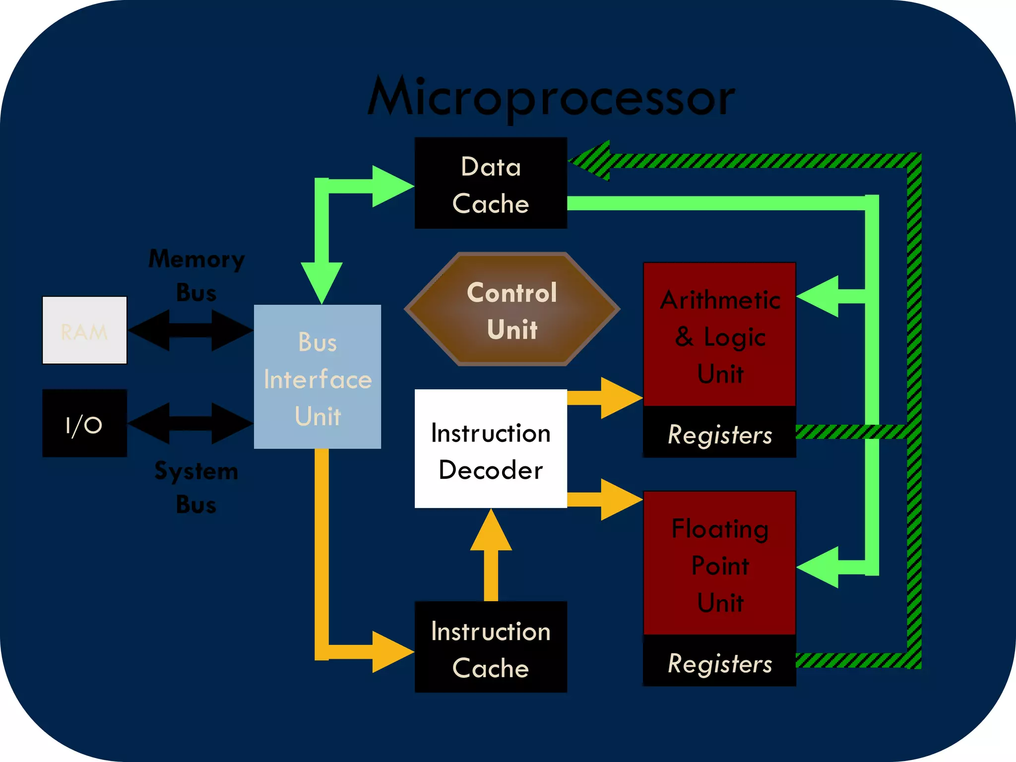
Microprocessors are central processing units contained on a single chip. They power modern computers and digital devices. A microprocessor has several components including a control unit, arithmetic logic unit, registers, instruction decoder, and bus interface unit. It communicates with memory and peripherals using an instruction set and addressing modes. Interfacing devices like USART, PPI, and DMA controllers allow microprocessors to connect to external components and transfer data. Interrupts and polling allow microprocessors to multitask and respond to events. Microprocessors have evolved over generations from 4-bit to 64-bit designs, increasing capabilities.
Overview of computers as programmable machines; defining characteristics and hardware/software components.
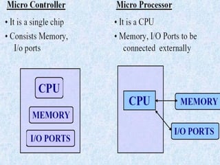
Definition of microprocessors as CPUs on chips; characteristics like instruction set, bus width, and clock speed.
Definition and components of microcontrollers, emphasizing their dedicated task functionality.
Historical progression of microprocessors since the Intel 4004, detailing features and key processors in each generation.Description of microprocessor architecture including units such as Arithmetic Logic Unit (ALU) and Control Unit.Explanation of instruction sets and various addressing modes that dictate data operations in microprocessors.
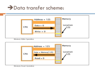
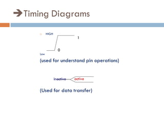
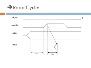
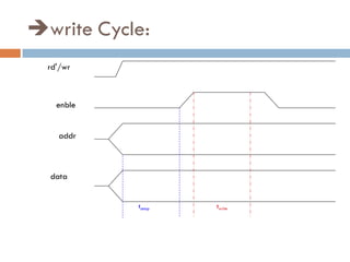
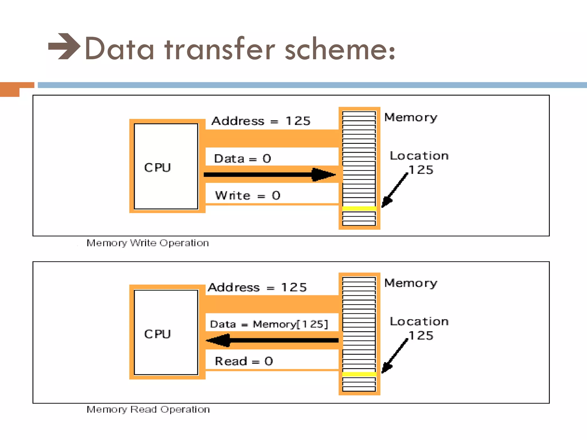
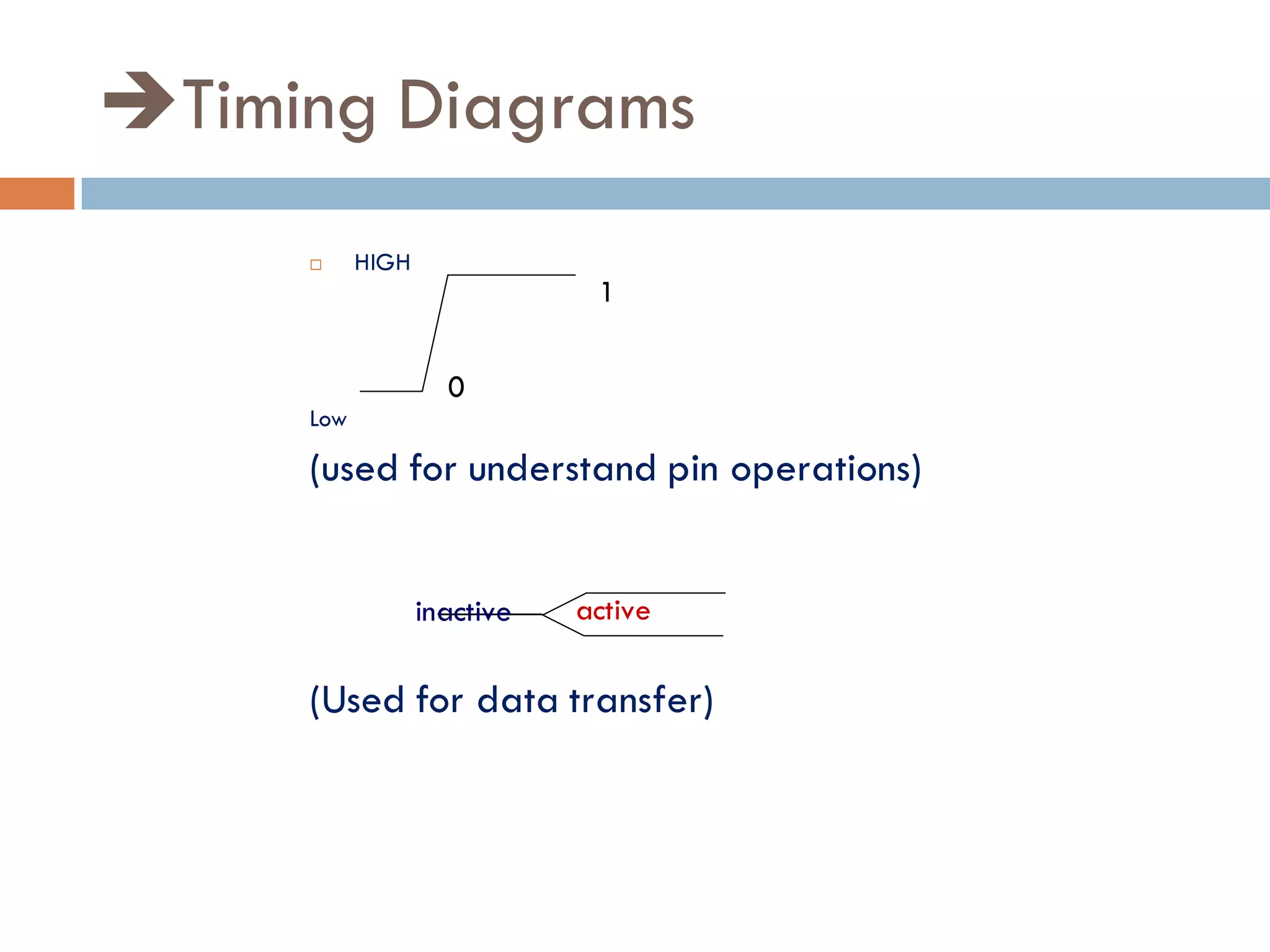
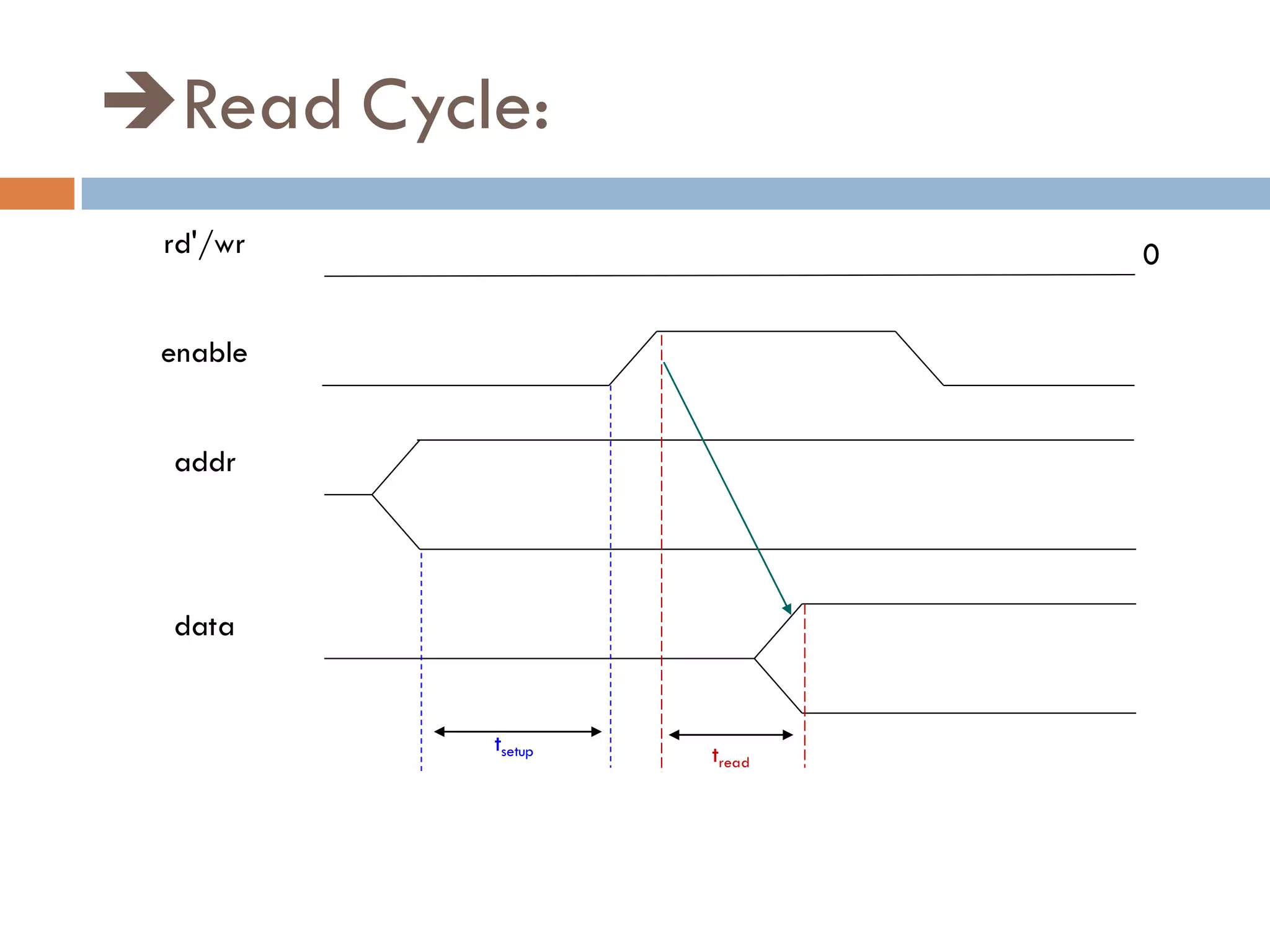
Data transfer mechanisms and timing diagrams to describe the operational timing of read/write cycles.
Discussion on interfacing techniques and devices such as USART and DMA controller for communication.Three modes of interfacing; continuous, polling, and interrupt mode for effective sensor communication.
Closing remarks on the microprocessor presentation.
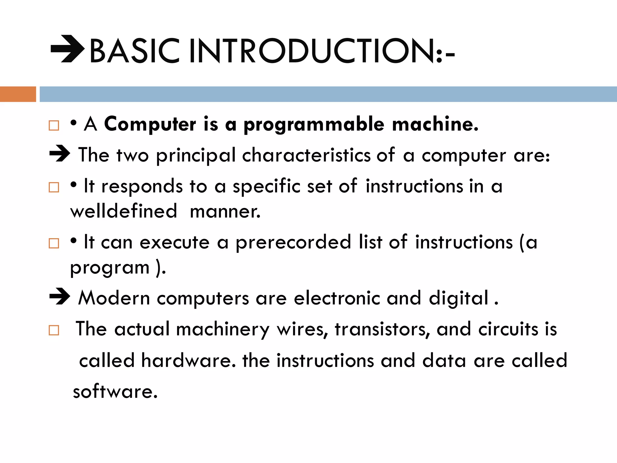
BASIC INTRODUCTION:-
•A Computer is a programmable machine.
The two principal characteristics of a computer are:
• It responds to a specific set of instructions in a
welldefined manner.
• It can execute a prerecorded list of instructions (a
program ).
Modern computers are electronic and digital .
The actual machinery wires, transistors, and circuits is
called hardware. the instructions and data are called
software.
5.
MICROPROCESSOR:-
A siliconchip that contains a CPU.
“CPU ON SIGLE CHIP”
In the world of personal computers, the terms
microprocessor and CPU are used interchangeably.
A microprocessor(sometimes abbreviated µP)is
a digital electronic component with miniaturized
transistors on a single semiconductor integrated
circuit (IC).
6.
One or moremicroprocessors
typically serve as a central
processing unit (CPU) in a
computer system or handheld
device.
7.
APPLICATIONS:
Microprocessors made possiblethe advent of the
microcomputer.
At the heart of all personal computers and most
working stations sits a microprocessor.
Microprocessors also control the logic of almost all
digital devices, from clock radios to fuel-injection
systems for automobiles.
8.
CHARACTERSTICS PARAMETERS:-
Three basiccharacteristics differentiate
microprocessors:
Instruction set: The set of instructions that the
microprocessor can execute.
Bus width : The number of bits processed in a
single instruction.
Clock speed : Given in megahertz (MHz), the
clock speed determines how many instructions per
second the processor can execute.
9.
NOTE:
In both cases,the higher the value, the more
powerful the CPU. For example, a 32 bit
microprocessor that runs at 50MHz is more
powerful than a 16-bit microprocessor that
runs at 50MHz.
10.
MICROCONTROLLER:-
“A Microcontroller isnothing but a complete
microcomputer”
Typically this includes a CPU, RAM, some form of
ROM, I/O ports, and timers.
a microcontroller is designed for a very specific task -
to control a particular system.
A microcontroller is meant to be more self-contained
and independent, and functions as a tiny, dedicated
computer.
12.
Evolution of MicroProcessor:-
History shows that the ancient Babylonians first began
using abacus(a primitive calculator made of beads)
in about 500B.C
in 1971 Intel corporation released worlds first
microprocessor the INTEL 4004, a 4- bit
microprocessor.
13.
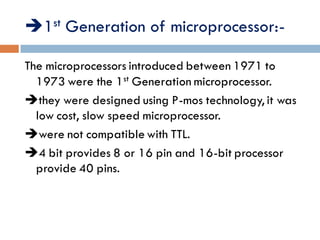
1st Generation ofmicroprocessor:-
The microprocessors introduced between 1971 to
1973 were the 1st Generation microprocessor.
they were designed using P-mos technology, it was
low cost, slow speed microprocessor.
were not compatible with TTL.
4 bit provides 8 or 16 pin and 16-bit processor
provide 40 pins.
14.
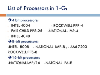
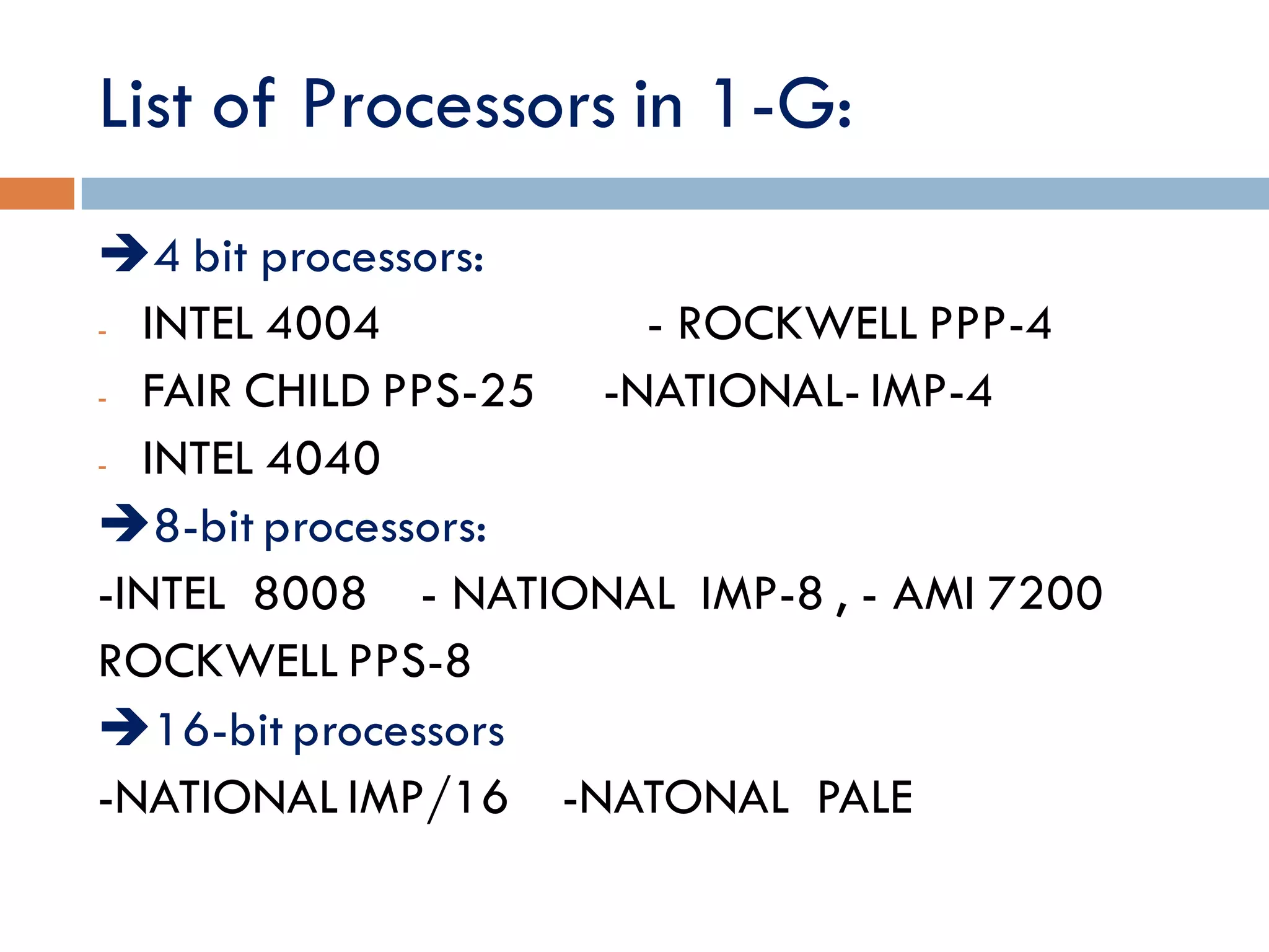
List of Processorsin 1-G:
4 bit processors:
- INTEL 4004 - ROCKWELL PPP-4
- FAIR CHILD PPS-25 -NATIONAL- IMP-4
- INTEL 4040
8-bit processors:
-INTEL 8008 - NATIONAL IMP-8 , - AMI 7200
ROCKWELL PPS-8
16-bit processors
-NATIONAL IMP/16 -NATONAL PALE
15.
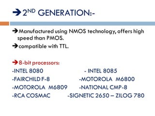
2ND GENERATION:-
Manufactured usingNMOS technology, offers high
speed than PMOS.
compatible with TTL.
LIST OF PROCESSORS:
8-bit processors:
-INTEL 8080 - INTEL 8085
-FAIRCHILD F-8 -MOTOROLA M6800
-MOTOROLA M6809 -NATIONAL CMP-8
-RCA COSMAC -SIGNETIC 2650 – ZILOG 780
16.
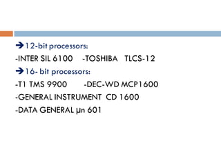
12-bit processors:
-INTER SIL6100 -TOSHIBA TLCS-12
16- bit processors:
-T1 TMS 9900 -DEC-WD MCP1600
-GENERAL INSTRUMENT CD 1600
-DATA GENERAL µn 601
17.
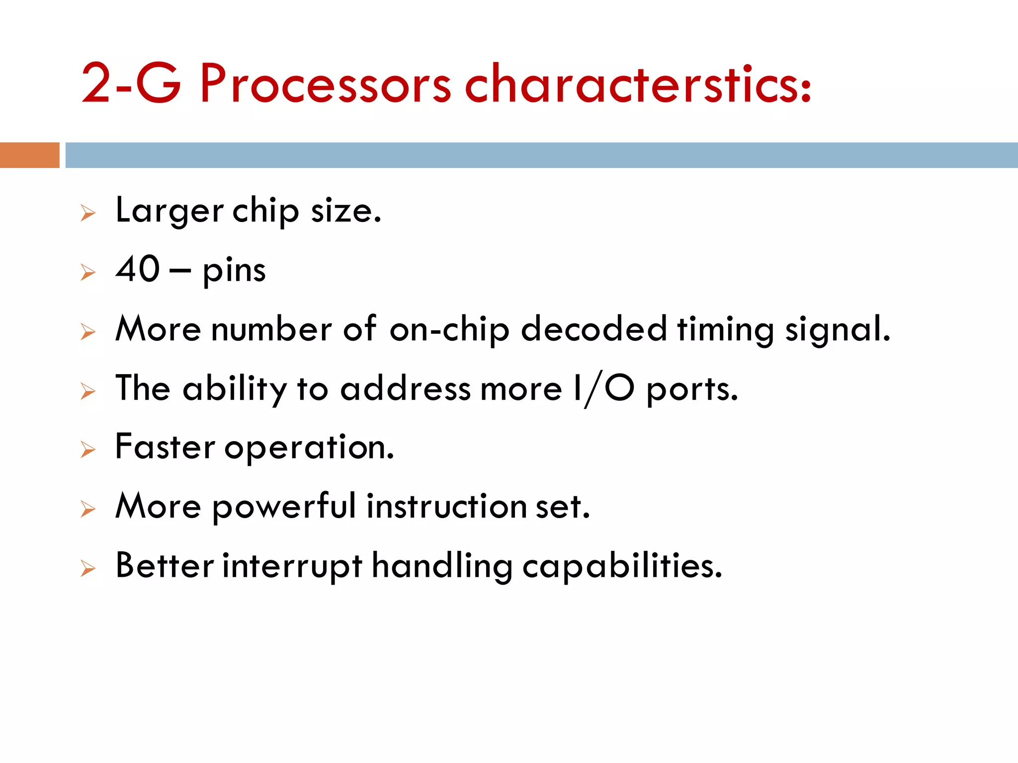
2-G Processors characterstics:
Larger chip size.
40 – pins
More number of on-chip decoded timing signal.
The ability to address more I/O ports.
Faster operation.
More powerful instruction set.
Better interrupt handling capabilities.
18.
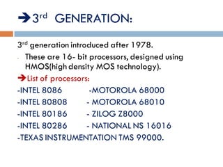
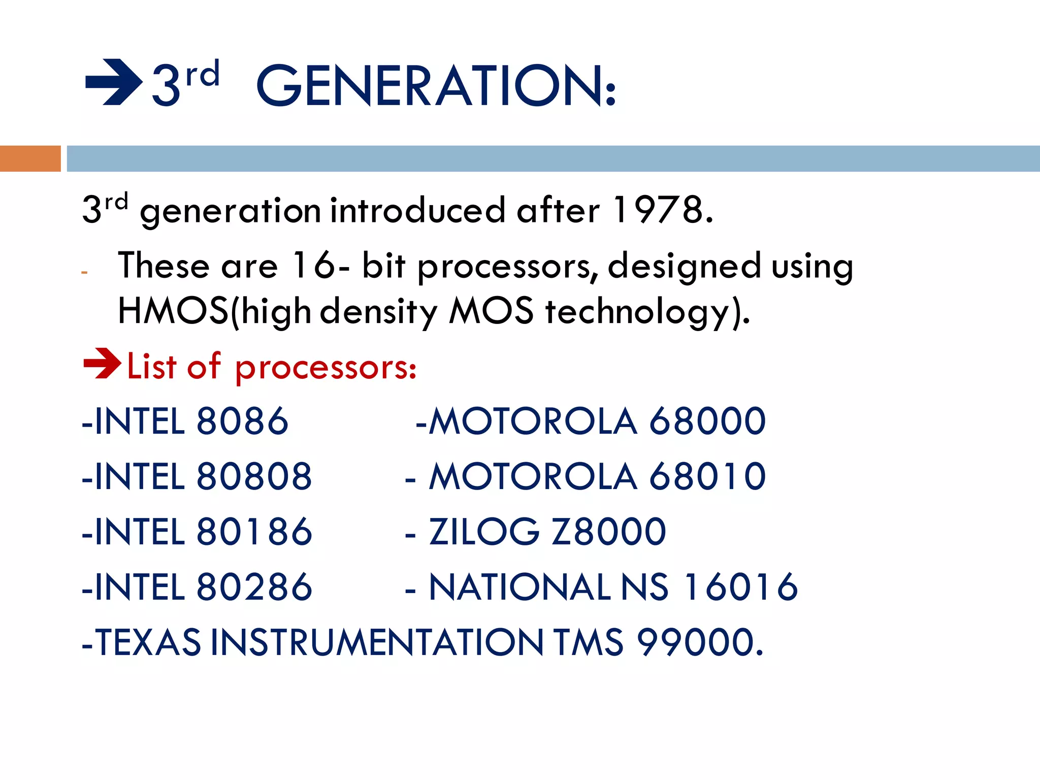
3rd GENERATION:
3rd generationintroduced after 1978.
- These are 16- bit processors, designed using
HMOS(high density MOS technology).
List of processors:
-INTEL 8086 -MOTOROLA 68000
-INTEL 80808 - MOTOROLA 68010
-INTEL 80186 - ZILOG Z8000
-INTEL 80286 - NATIONAL NS 16016
-TEXAS INSTRUMENTATION TMS 99000.
19.
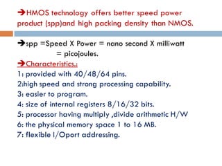
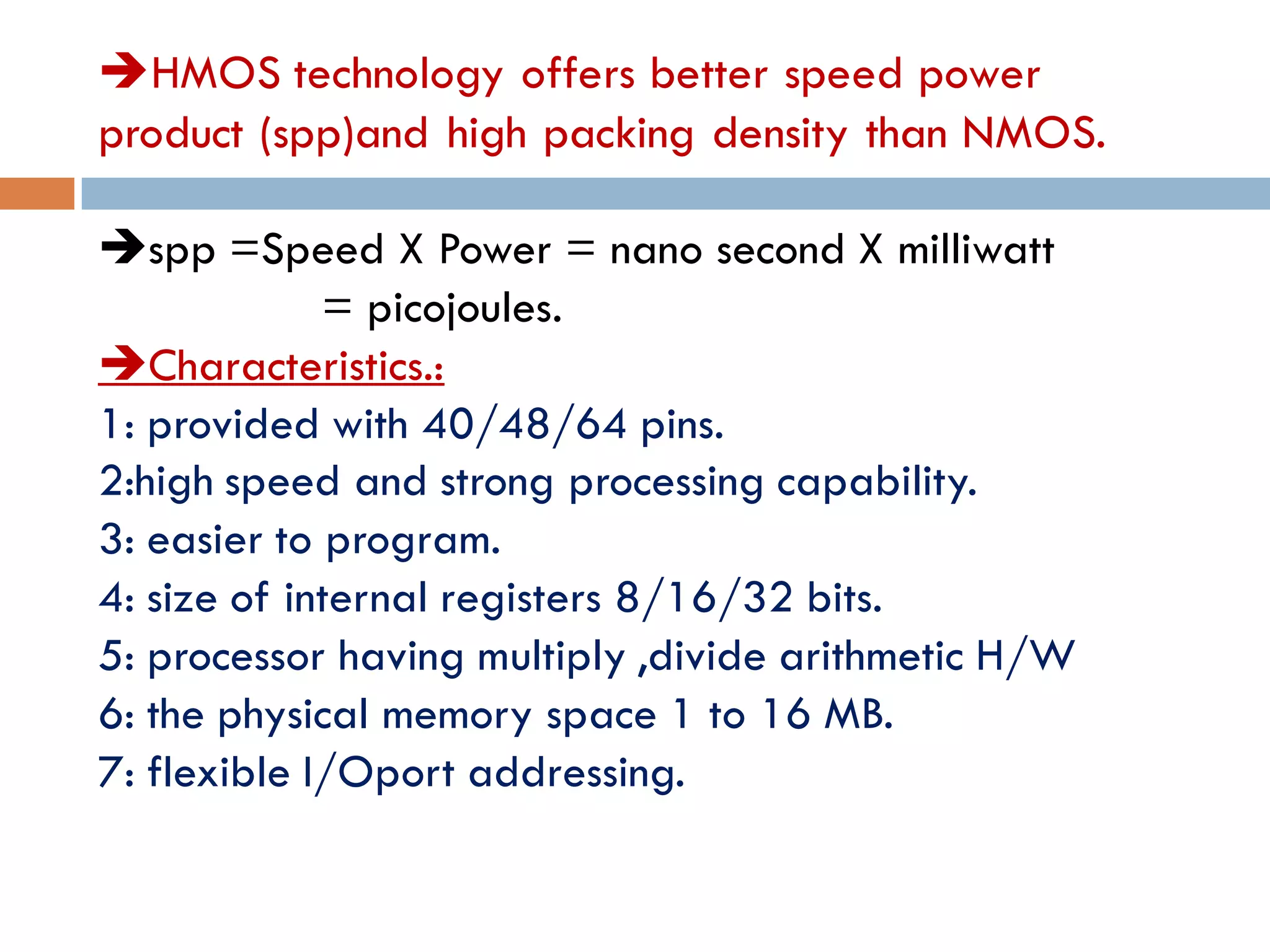
HMOS technology offersbetter speed power
product (spp)and high packing density than NMOS.
spp =Speed X Power = nano second X milliwatt
= picojoules.
Characteristics.:
1: provided with 40/48/64 pins.
2:high speed and strong processing capability.
3: easier to program.
4: size of internal registers 8/16/32 bits.
5: processor having multiply ,divide arithmetic H/W
6: the physical memory space 1 to 16 MB.
7: flexible I/Oport addressing.
20.
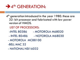
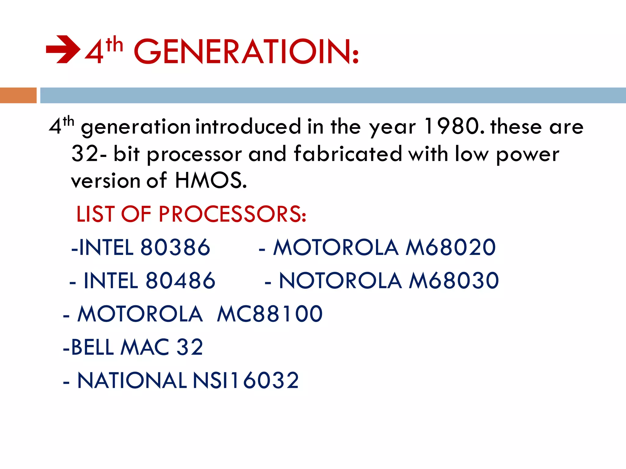
4th GENERATIOIN:
4th generationintroduced in the year 1980. these are
32- bit processor and fabricated with low power
version of HMOS.
LIST OF PROCESSORS:
-INTEL 80386 - MOTOROLA M68020
- INTEL 80486 - NOTOROLA M68030
- MOTOROLA MC88100
-BELL MAC 32
- NATIONAL NSI16032
21.
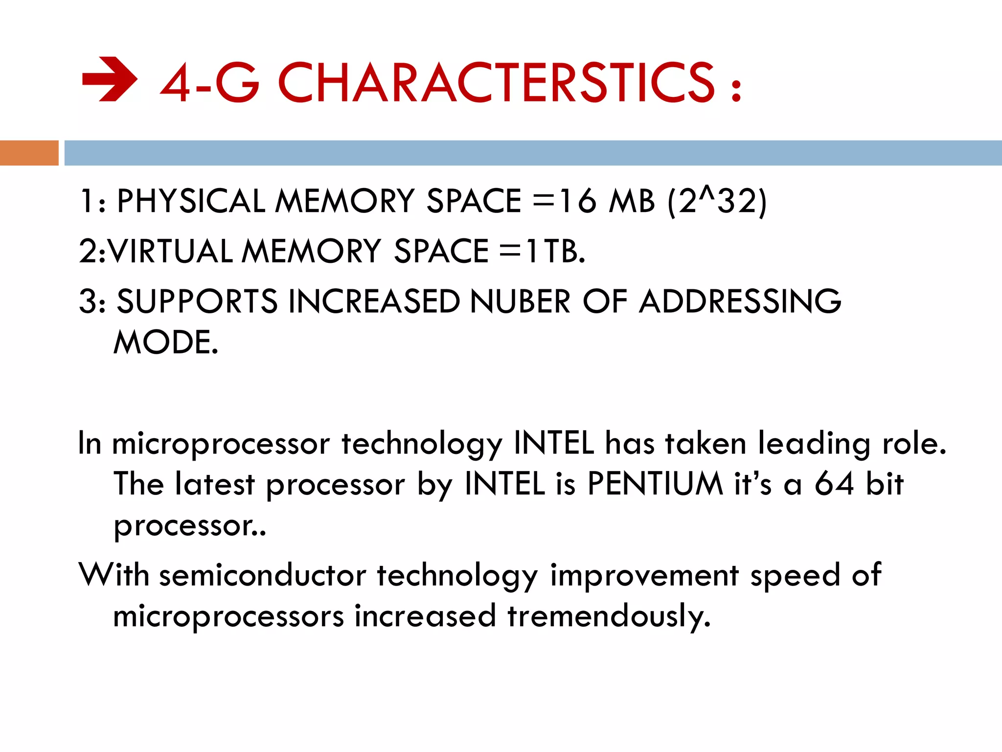
4-G CHARACTERSTICS:
1: PHYSICAL MEMORY SPACE =16 MB (2^32)
2:VIRTUAL MEMORY SPACE =1TB.
3: SUPPORTS INCREASED NUBER OF ADDRESSING
MODE.
In microprocessor technology INTEL has taken leading role.
The latest processor by INTEL is PENTIUM it’s a 64 bit
processor..
With semiconductor technology improvement speed of
microprocessors increased tremendously.
Bus Interface Unit
Receives instructions & data from main memory
Instructions are then sent to the instruction cache, data to
the data cache
Also receives the processed data and sends it to the
main memory
25.
Instruction Decoder
Thisunit receives the programming instructions and
decodes them into a form that is understandable by the
processing units, i.e. the ALU or FPU
Then, it passes on the decoded instruction to the ALU or
FPU
26.
Arithmetic & LogicUnit (ALU)
Also known as the “Integer Unit”
It performs whole-number math calculations (subtract,
multiply, divide, etc) comparisons (is greater than, is
smaller than, etc.) and logical operations (NOT, OR, AND,
etc)
The new breed of popular uPs have not one but two
almost identical ALU’s that can do calculations
simultaneously, doubling the capability
27.
Floating-Point Unit (FPU)
Also known as the “Numeric Unit”
It performs calculations that involve numbers represented
in the scientific notation (also known as floating-point
numbers).
This notation can represent extremely small and extremely
large numbers in a compact form
Floating-point calculations are required for doing graphics,
engineering and scientific work
The ALU can do these calculations as well, but will do them
very slowly
28.
Registers
Both ALU& FPU have a very small amount of super-fast
private memory placed right next to them for their
exclusive use. These are called registers
The ALU & FPU store intermediate and final results from
their calculations in these registers
Processed data goes back to the data cache and then to
main memory from these registers
29.
Control Unit
Thebrain of the uP
Manages the whole uP
Tasks include fetching instructions & data, storing
data, managing input/output devices
30.
That was thestructure, now
let’s talk about the language of
a μP
31.
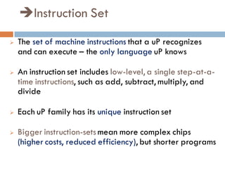
Instruction Set
Theset of machine instructions that a uP recognizes
and can execute – the only language uP knows
An instruction set includes low-level, a single step-at-a-
time instructions, such as add, subtract, multiply, and
divide
Each uP family has its unique instruction set
Bigger instruction-sets mean more complex chips
(higher costs, reduced efficiency), but shorter programs
32.
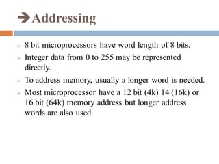
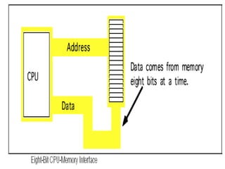
Addressing
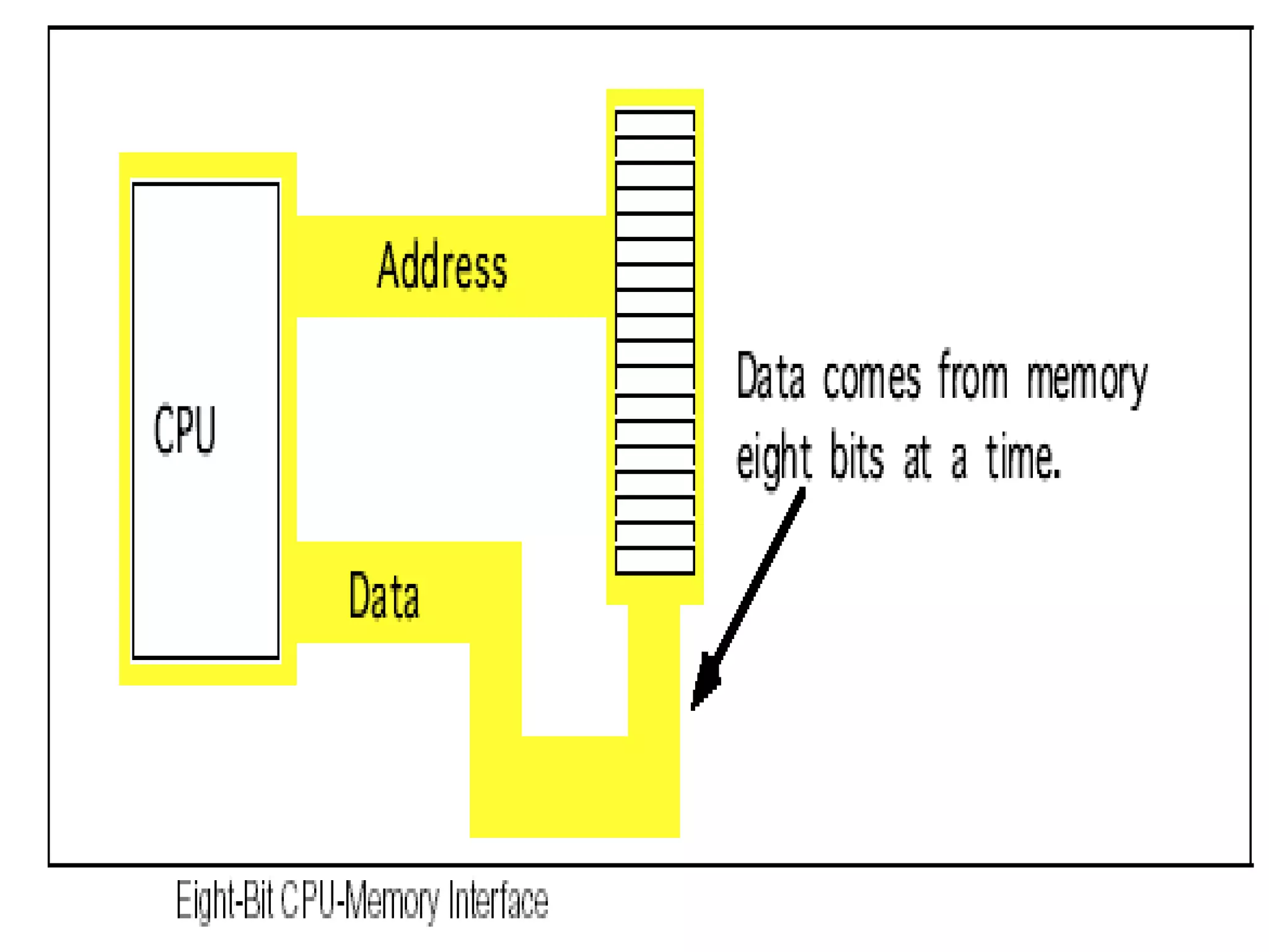
8 bitmicroprocessors have word length of 8 bits.
Integer data from 0 to 255 may be represented
directly.
To address memory, usually a longer word is needed.
Most microprocessor have a 12 bit (4k) 14 (16k) or
16 bit (64k) memory address but longer address
words are also used.
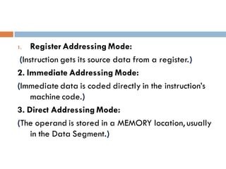
1. Register AddressingMode:
(Instruction gets its source data from a register.)
2. Immediate Addressing Mode:
(Immediate data is coded directly in the instruction’s
machine code.)
3. Direct Addressing Mode:
(The operand is stored in a MEMORY location, usually
in the Data Segment.)
35.
4. Register IndirectAddressing Mode:
(RegisterIndirect Addressing uses a register instead of
a constant (as in d irect addressing) to specify the
16-bit offset address of the operand.).
5. Based Addressing Mode:
(The operand is located at the address given by
adding an 8- or 16-bit displacement to either BX or
BP and combining the result with a segment
register.)
36.
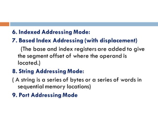
6. Indexed AddressingMode:
7. Based Index Addressing (with displacement)
(The base and index registers are added to give
the segment offset of where the operand is
located.)
8. String Addressing Mode:
( A string is a series of bytes or a series of words in
sequential memory locations)
9. Port Addressing Mode
37.
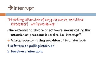
Interrupt
“Divertingattention of anypersonor machine
(processor) while working”
: the external hardware or software means calling the
attention of processor is said to be interrupt”
Microprocessor having provision of two interrupt:
1:software or polling interrupt
2: hardware interrupts.
“To communicatewith micro processor interfacing is
required “
To implement serial communicati0n in microprocessor
system we need basically two devices.
1: Parallel to serial converter.
2. Serial to parallel converter.
“To transmit byte data it is necessary to convert byte
into serial bits. This can be done by using the parallel
to serial converter . Similarly at reception those serial
bits must be converted in parallel.”
46.
interfacing devices:-
USART:8251 A(universal synchronous asynchronous
receiver - transmitter):
-its a programmable chip designed for synchronous
and asynchronous serial data communication.
- It is compatible with 8085. it allows full duplex
transmission and reception.
-it is a in 28 pin DIP.
47.
8255 PPI(Programmable PeripheralInterface)
-The INTEL 8255A is a device used to implement
parallel data transfer between processor and slow
peripheral devices like ADC,DAC, keyboard of
segment display etc.
- It works on three modes..
- 1: Mode-0 simple I/O port.
- 2: Mode-1 Handshake I/O port.
- 3: Mode-2 Bidirectional I/O port.
48.
DMA controller –INTEL 8257
-The DMA controller has been developed for
8085/8086/8088 microprocessor based systems.
- It is a device dedicated to perform a high speed
data transfer between memory and I/O device.
- 8257 has four channels and so it can be used to
provide direct memory access to four I/O devices.
49.
Keyboard & displaycontroller-INTEL 8279:
- The Intel -8279 is a dedicated controller specially
developed for interfacing keyboard and display
devices to 8085/
-
50.
Interfacing Issues
Three basicmodes:
1. Continuous dedicated monitoring of the sensor
by the microprocessor
2. Polling the sensor
3. Interrupt mode
51.
Continuous mode
Microprocessoris dedicated for use with the
sensor
Its output is monitored by the microprocessor
continuously
The microprocessor reads the sensor’s output at
a given rate
Output is then used to act
52.
Poling mode
Sensoroperates as if the microprocessor did not
exist.
Its output is monitored by the microprocessor
The microprocessor reads the sensor’s output at
a given rate or intervals – poling
Output is then used to act
53.
Interrupt mode
Microprocessoris in sleep mode
Outputs of the sensor are not being processed
Upon a given event, microprocessor wakes up
through one of its interrupt options.
The sensor activates the interrupt
54.
Note:
Interrupts canbe timed
Interrupts can be issued by sources other than
the sensor
The microprocessor may be involved in other
functions, separate from the sensor, such as
control of an actuator
Feedback from actuators may also be used to
perform interrupts