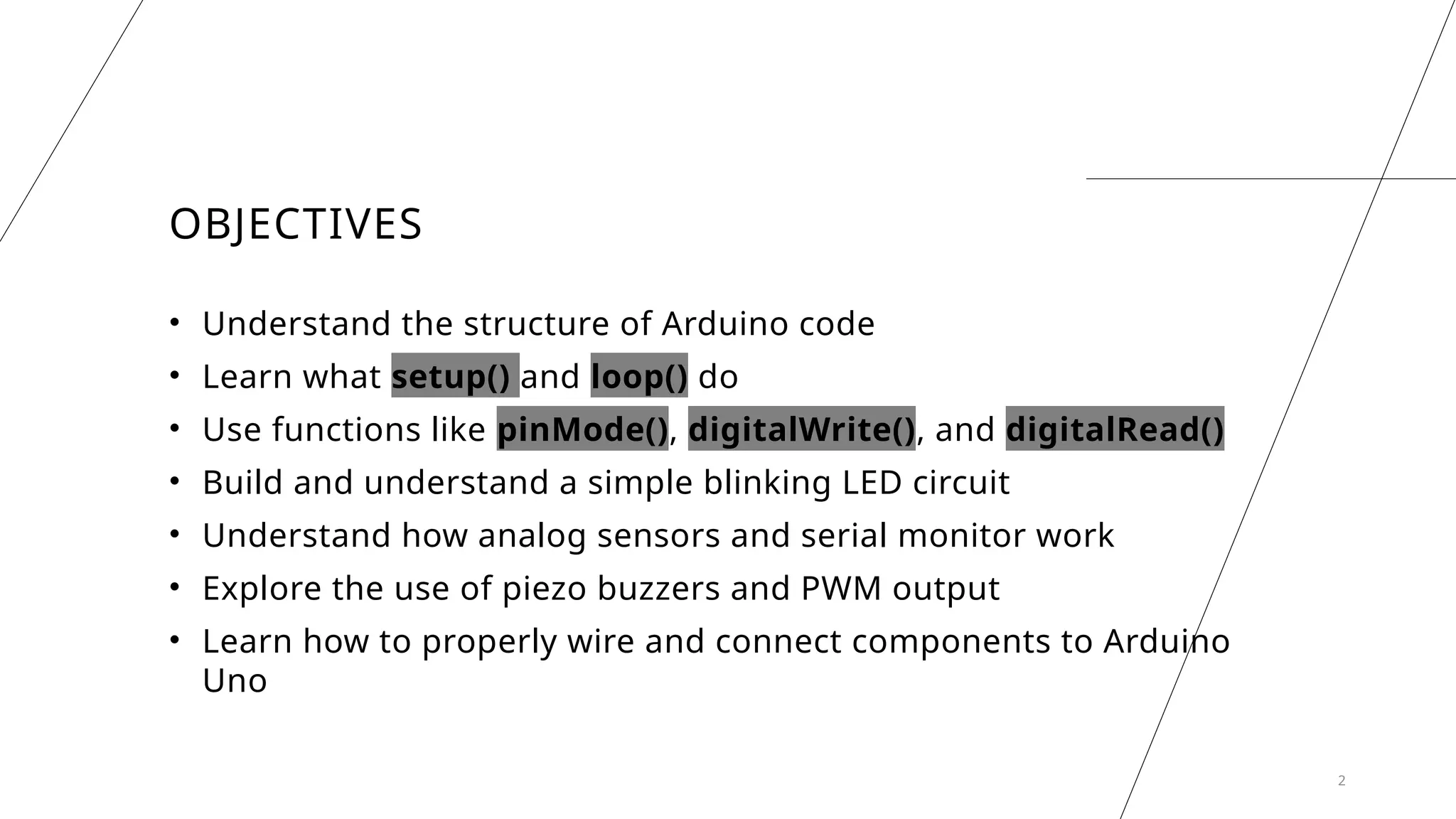
OBJECTIVES
• Understand thestructure of Arduino code
• Learn what setup() and loop() do
• Use functions like pinMode(), digitalWrite(), and digitalRead()
• Build and understand a simple blinking LED circuit
• Understand how analog sensors and serial monitor work
• Explore the use of piezo buzzers and PWM output
• Learn how to properly wire and connect components to Arduino
Uno
2
3.
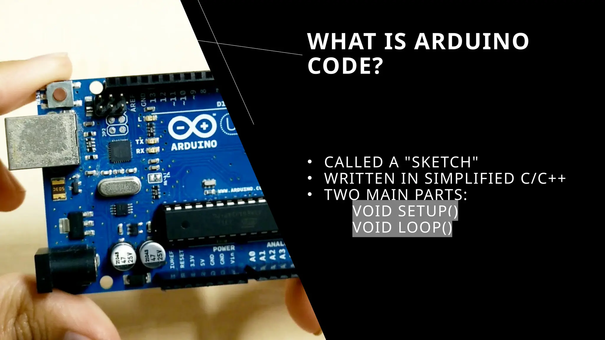
WHAT IS ARDUINO
CODE?
•CALLED A "SKETCH"
• WRITTEN IN SIMPLIFIED C/C++
• TWO MAIN PARTS:
VOID SETUP()
VOID LOOP()
4.
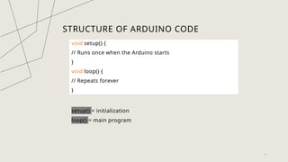
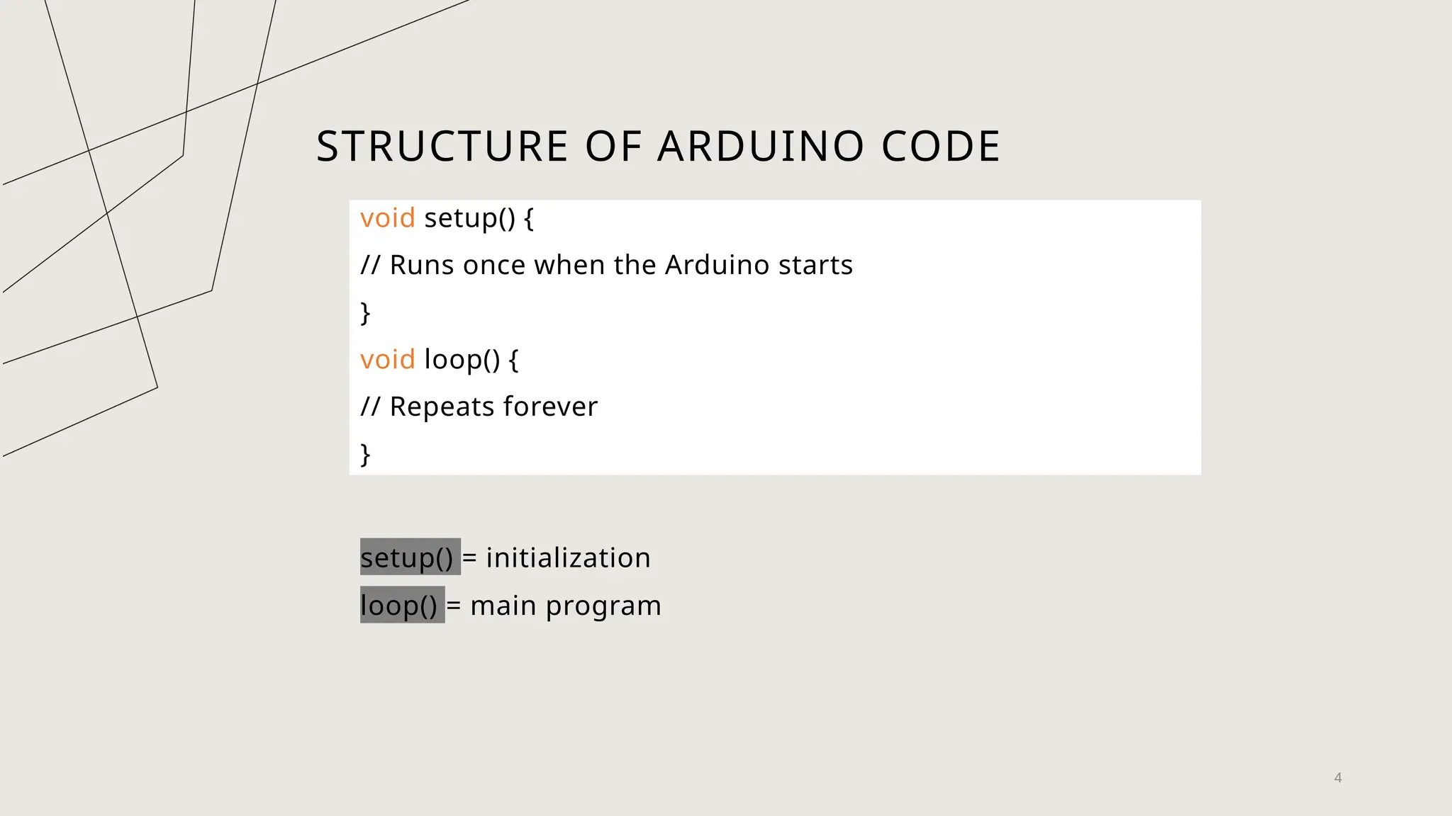
STRUCTURE OF ARDUINOCODE
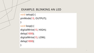
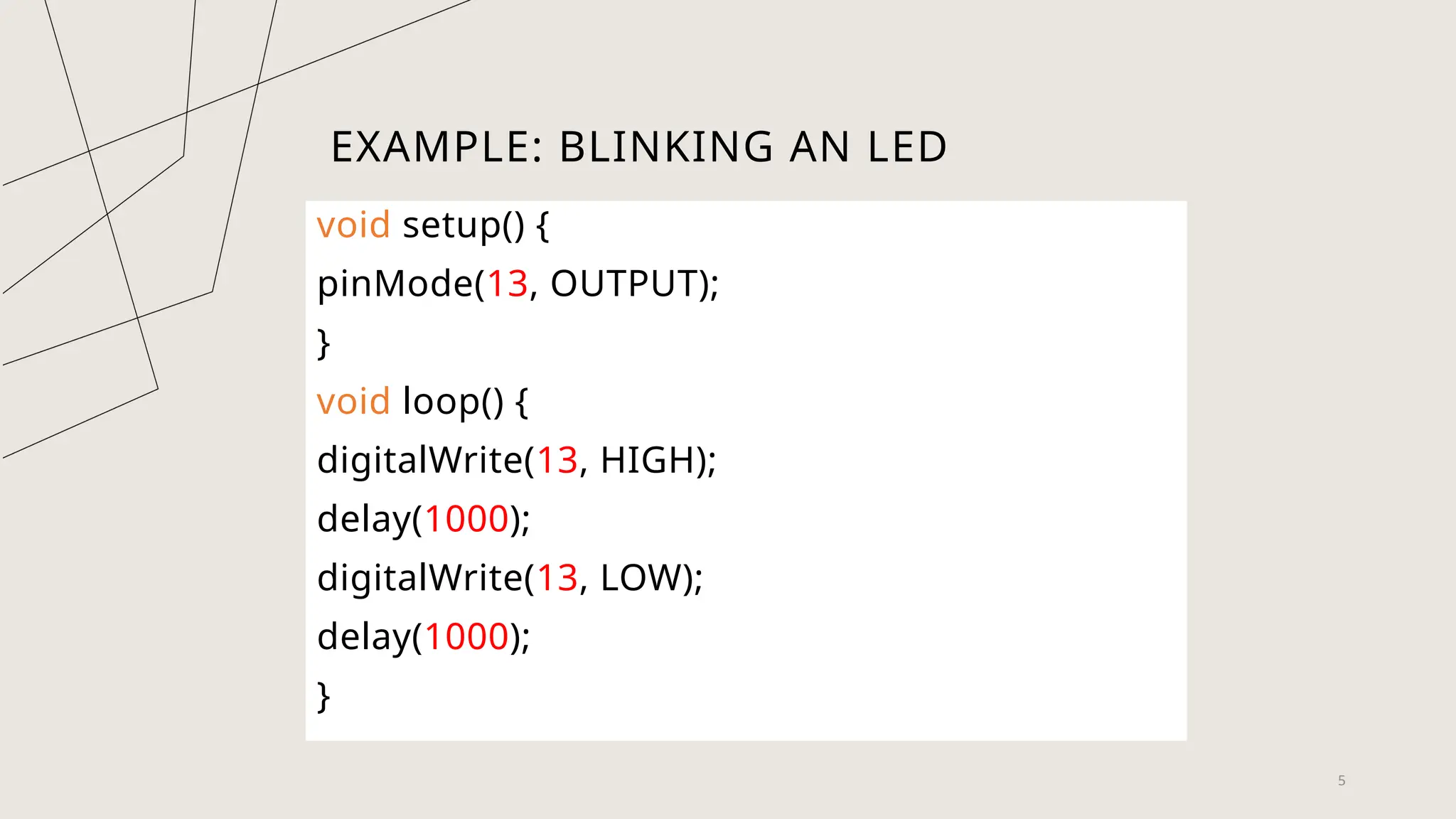
void setup() {
// Runs once when the Arduino starts
}
void loop() {
// Repeats forever
}
setup() = initialization
loop() = main program
4
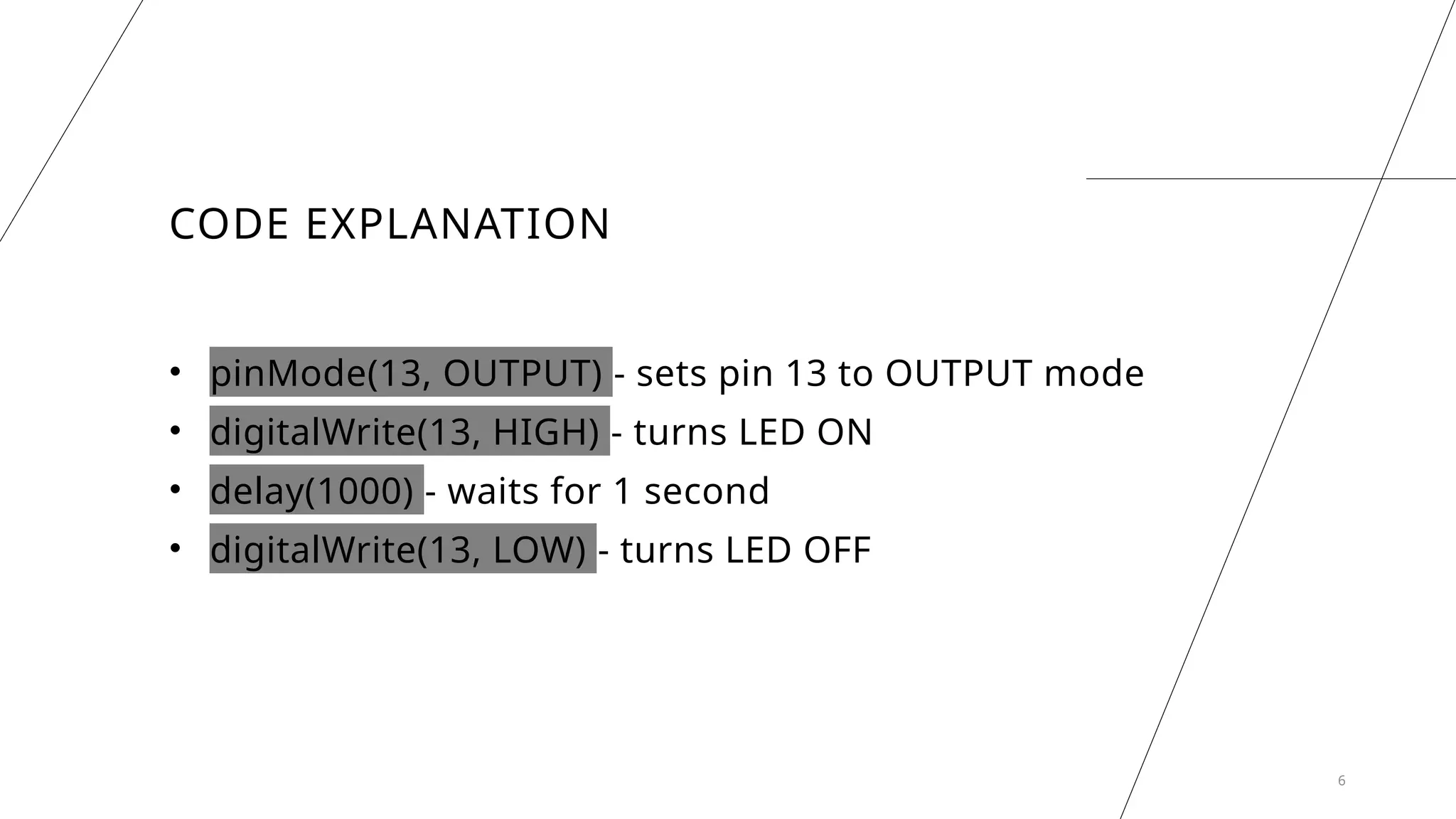
CODE EXPLANATION
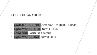
• pinMode(13,OUTPUT) - sets pin 13 to OUTPUT mode
• digitalWrite(13, HIGH) - turns LED ON
• delay(1000) - waits for 1 second
• digitalWrite(13, LOW) - turns LED OFF
6
7.
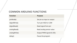
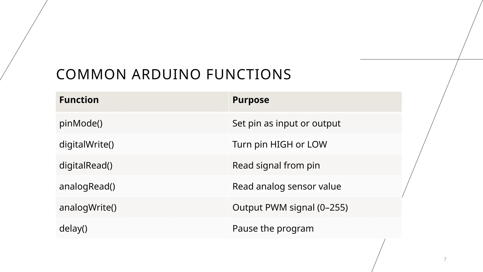
COMMON ARDUINO FUNCTIONS
7
FunctionPurpose
pinMode() Set pin as input or output
digitalWrite() Turn pin HIGH or LOW
digitalRead() Read signal from pin
analogRead() Read analog sensor value
analogWrite() Output PWM signal (0–255)
delay() Pause the program
8.
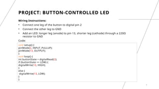
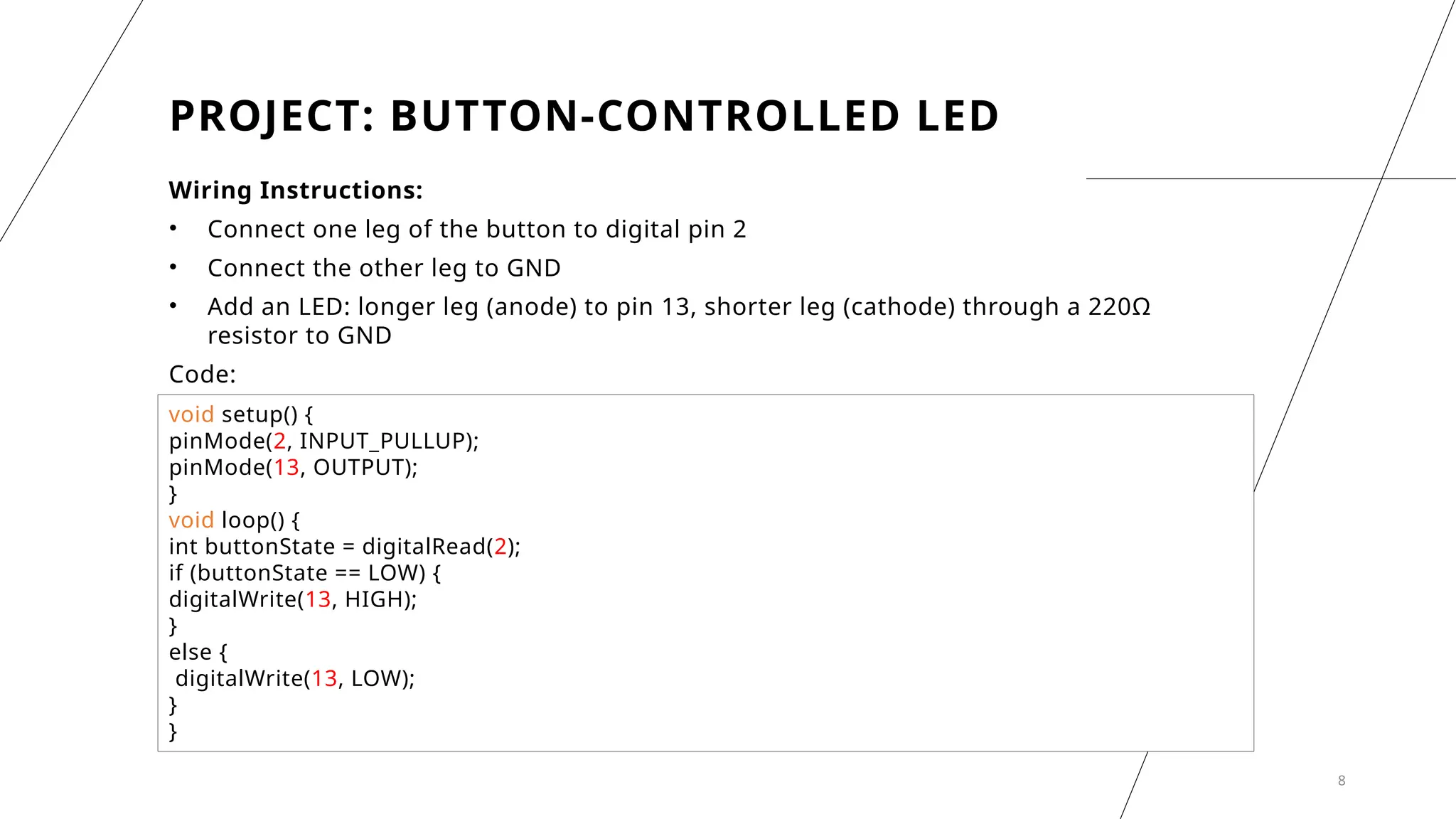
PROJECT: BUTTON-CONTROLLED LED
WiringInstructions:
• Connect one leg of the button to digital pin 2
• Connect the other leg to GND
• Add an LED: longer leg (anode) to pin 13, shorter leg (cathode) through a 220Ω
resistor to GND
Code:
8
void setup() {
pinMode(2, INPUT_PULLUP);
pinMode(13, OUTPUT);
}
void loop() {
int buttonState = digitalRead(2);
if (buttonState == LOW) {
digitalWrite(13, HIGH);
}
else {
digitalWrite(13, LOW);
}
}
9.
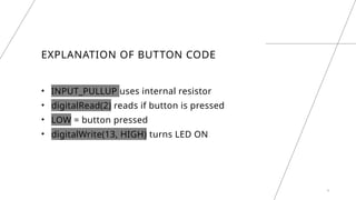
EXPLANATION OF BUTTONCODE
• INPUT_PULLUP uses internal resistor
• digitalRead(2) reads if button is pressed
• LOW = button pressed
• digitalWrite(13, HIGH) turns LED ON
9
10.
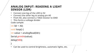
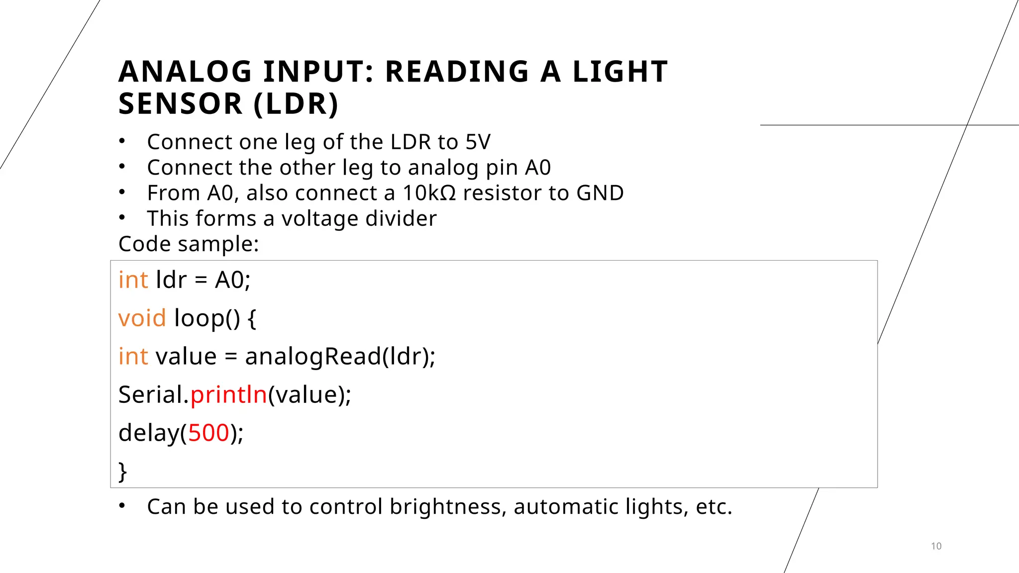
ANALOG INPUT: READINGA LIGHT
SENSOR (LDR)
• Connect one leg of the LDR to 5V
• Connect the other leg to analog pin A0
• From A0, also connect a 10kΩ resistor to GND
• This forms a voltage divider
Code sample:
10
int ldr = A0;
void loop() {
int value = analogRead(ldr);
Serial.println(value);
delay(500);
}
• Can be used to control brightness, automatic lights, etc.
11.
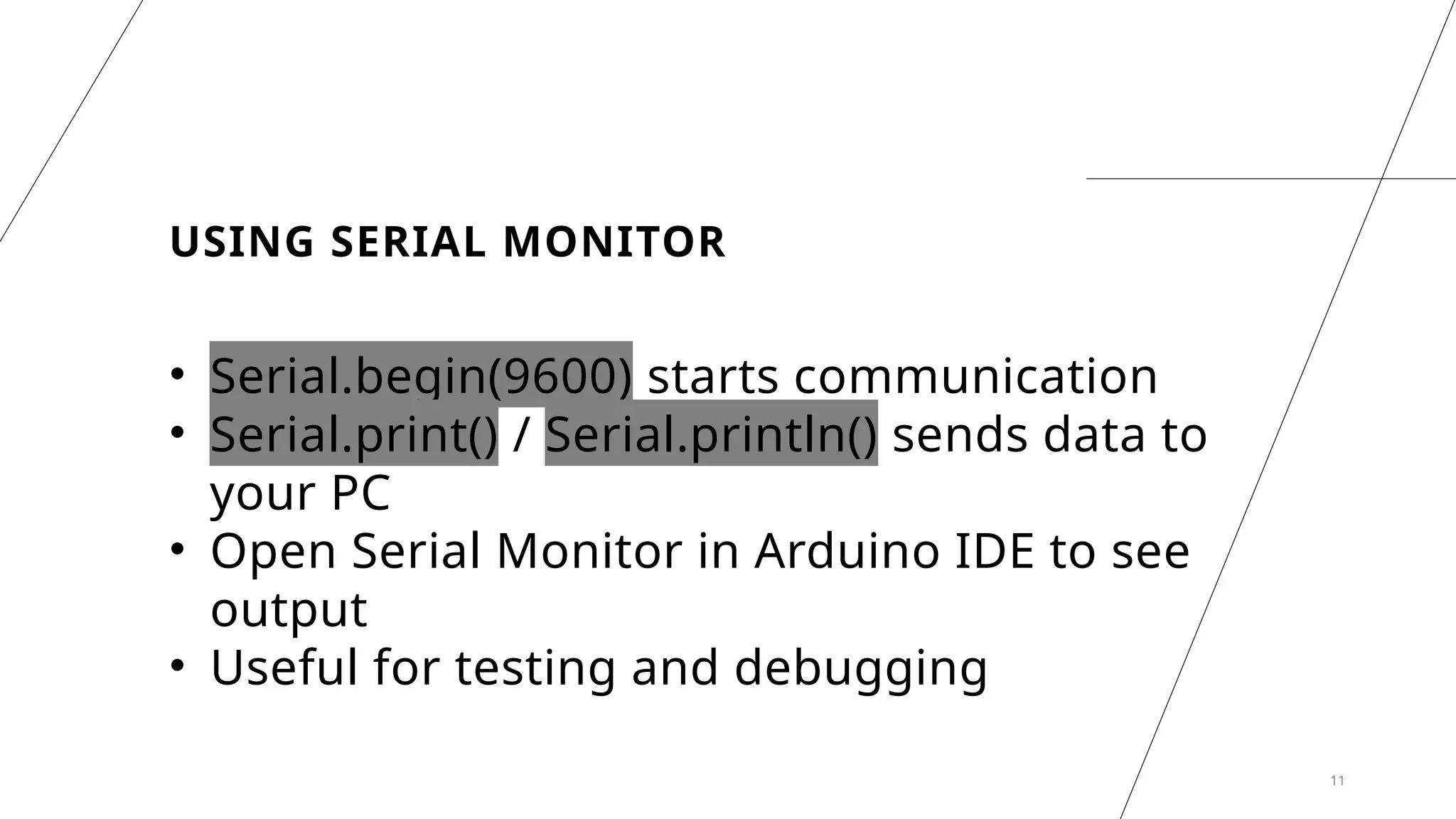
USING SERIAL MONITOR
•Serial.begin(9600) starts communication
• Serial.print() / Serial.println() sends data to
your PC
• Open Serial Monitor in Arduino IDE to see
output
• Useful for testing and debugging
11
12.
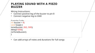
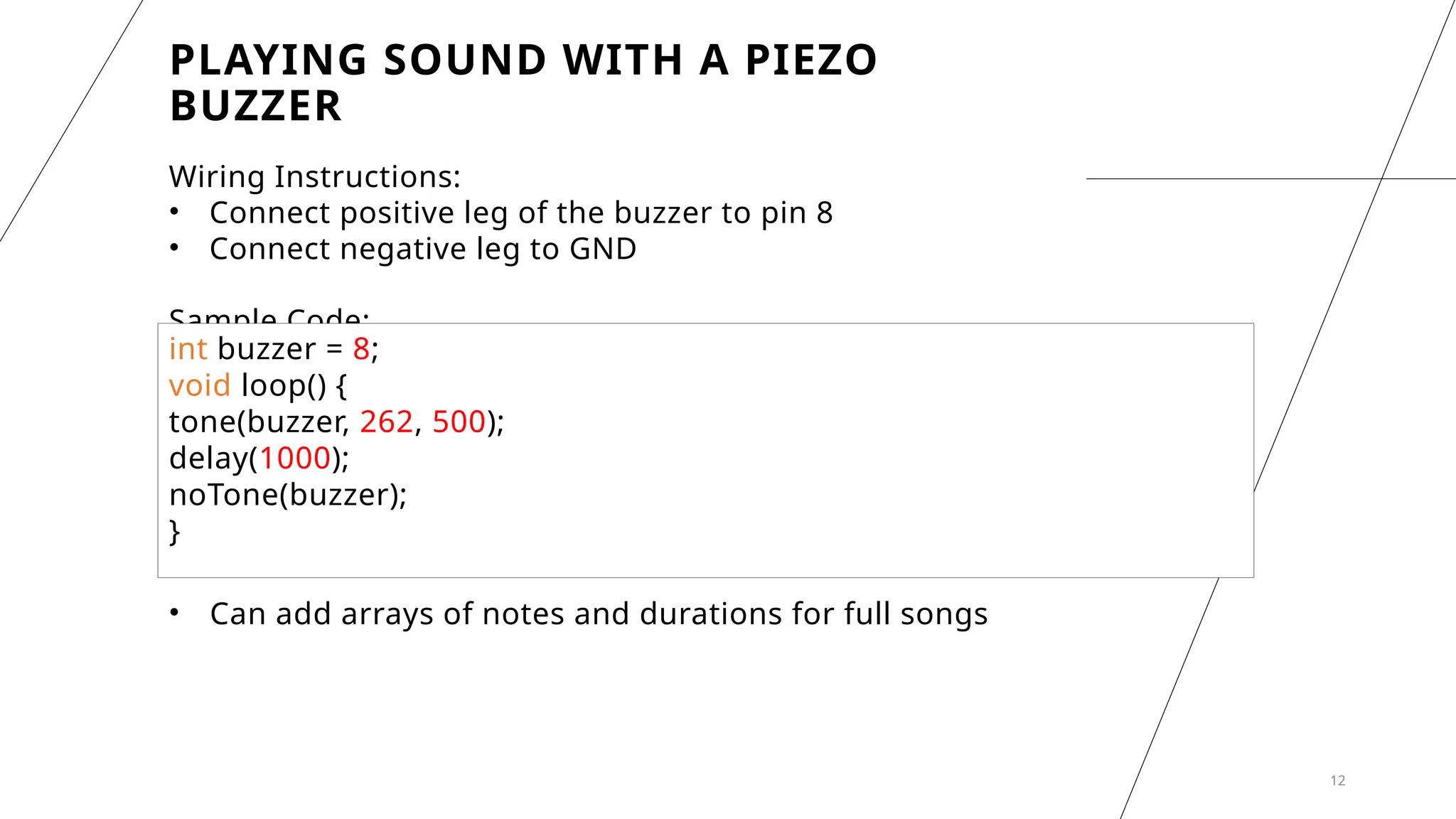
PLAYING SOUND WITHA PIEZO
BUZZER
Wiring Instructions:
• Connect positive leg of the buzzer to pin 8
• Connect negative leg to GND
Sample Code:
12
int buzzer = 8;
void loop() {
tone(buzzer, 262, 500);
delay(1000);
noTone(buzzer);
}
• Can add arrays of notes and durations for full songs
13.
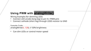
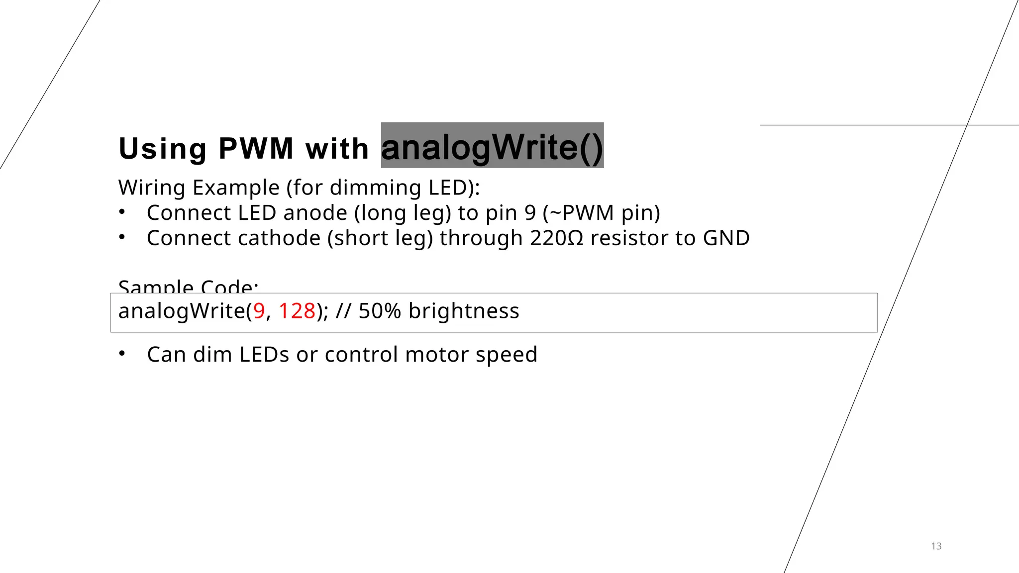
Using PWM withanalogWrite()
Wiring Example (for dimming LED):
• Connect LED anode (long leg) to pin 9 (~PWM pin)
• Connect cathode (short leg) through 220Ω resistor to GND
Sample Code:
13
analogWrite(9, 128); // 50% brightness
• Can dim LEDs or control motor speed
14.
PRACTICE
QUESTIONS
• What doessetup() do?
• How is loop() different?
• What happens if you remove
delay()?
• What is the value range of
analogRead()?
• How do you play sound
using a buzzer?
• How would you wire an LDR
to A0 properly?
15.
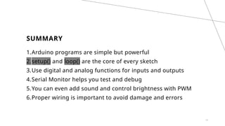
SUMMARY
1.Arduino programs aresimple but powerful
2.setup() and loop() are the core of every sketch
3.Use digital and analog functions for inputs and outputs
4.Serial Monitor helps you test and debug
5.You can even add sound and control brightness with PWM
6.Proper wiring is important to avoid damage and errors
15