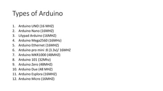
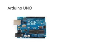
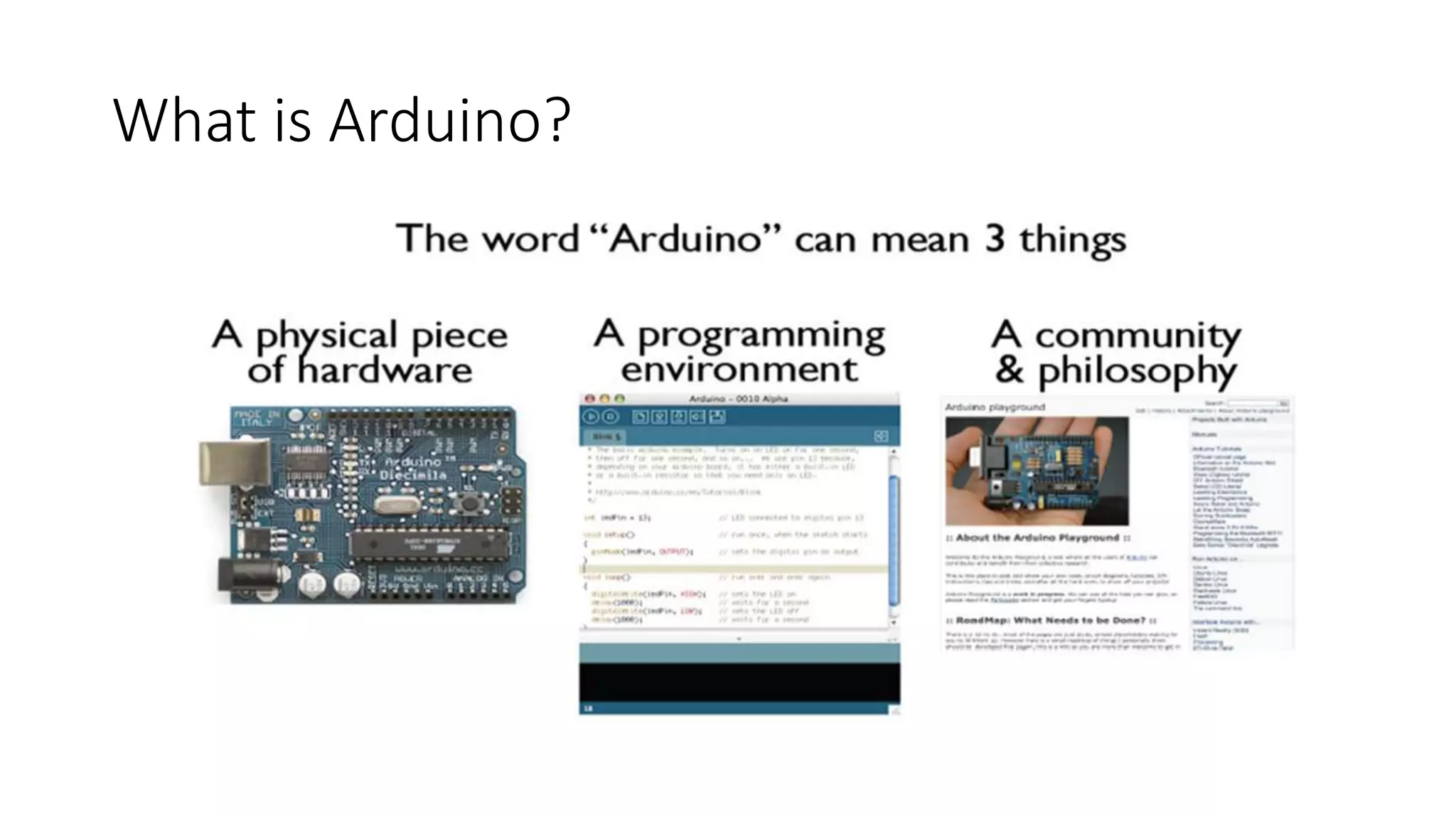
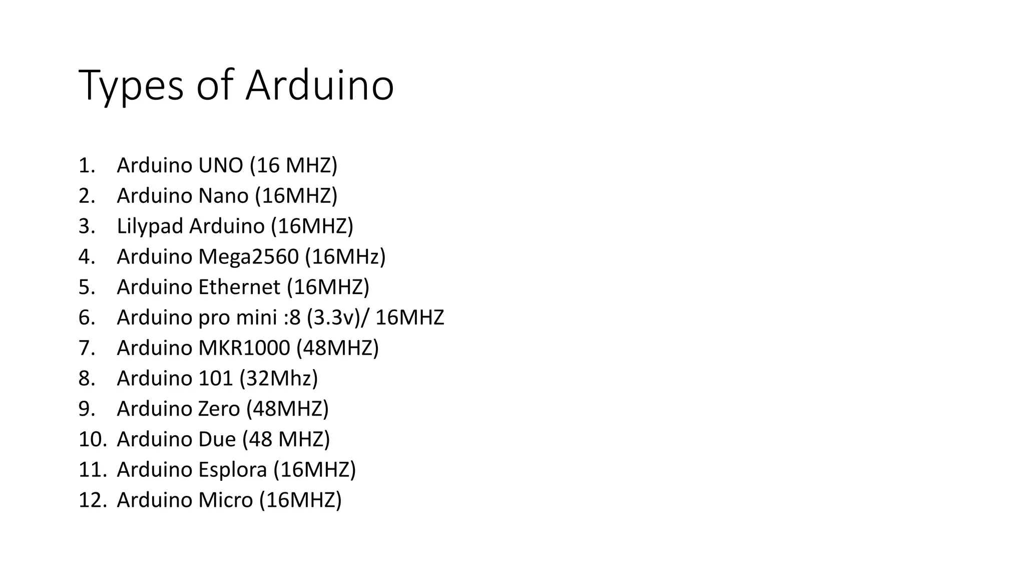
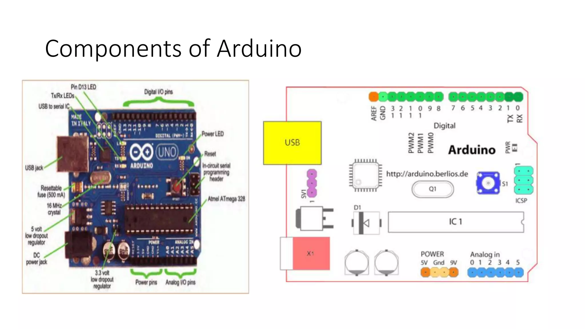
KEMBAR78
Arduino and its hw architecture | PPTX
ARDUINO
Its Hardware Architecture
Outline
What is Arduino?
What is Arduino?
Arduino is an Open-source microcontroller board, with an
associated development environment. Arduino senses
the environment by receiving inputs from many sensors,
and affects its surroundings by controlling lights, motors,
and other actuators.
Types of Arduino
1. Arduino UNO (16 MHZ)
2. Arduino Nano (16MHZ)
3. Lilypad Arduino (16MHZ)
4. Arduino Mega2560 (16MHz)
5. Arduino Ethernet (16MHZ)
6. Arduino pro mini :8 (3.3v)/ 16MHZ
7. Arduino MKR1000 (48MHZ)
8. Arduino 101 (32Mhz)
9. Arduino Zero (48MHZ)
10. Arduino Due (48 MHZ)
11. Arduino Esplora (16MHZ)
12. Arduino Micro (16MHZ)
Arduino UNO
Components of Arduino
• Analog Reference pin (orange)
• Digital Ground (light green)
• Digital Pins 2-13 (green)
• Digital Pins 0-1/Serial In/Out - TX/RX (dark green) - These pins cannot be used for digital i/o
(digital Read and digital Write) if you are also using serial communication (e.g. Serial.begin).
• Reset Button - S1 (dark blue)
• In-circuit Serial Programmer (blue-green)
• Analog In Pins 0-5 (light blue)
• Power and Ground Pins (power: orange, grounds: light orange)
• External Power Supply In (9-12VDC) - X1 (pink)
• Toggles External Power and USB Power (place jumper on two pins closest to desired supply) - SV1
(purple)
• USB (used for uploading sketches to the board and for serial communication between the board
and the computer; can be used to power the board) (yellow)
Arduino Architecture
• Use Harvard Architecture 1.
• It consist of 2 memories such as program memory and data memory.
• Data is stored in data memory and program is stored in flash program
memory.
• MicroController: AtMega 328
• It has 32KB of flash memory, 2KB of SRAM, 1KB of EPROM and
operates with 16MHZ clock speed.
• Boot Loader (0.5 KB)
Arduino Architecture
The Basic working of CPU Atmega 328:-
 The data is uploaded in serial via the port (being uploaded from the
computer’s Arduino IDE). The data is decoded and then the instructions
are sent to instruction register and it decodes the instructions on the
same clock pulse.
 On the next clock pulse the next set of instructions are loaded in
instruction register.
 In general purpose registers the registers are of 8-bit but there are 3
“16-bit” registers also.
 8-bit registers are used to store data for normal calculations and
results.
 16-bit registers are used to store data of timer counter in 2 different
register.Eg. X-low & X-high.
 EEPROM stores data permanently even if the power is cut out.
Programming inside a EEPROM is slow.
 Interrupt Unit checks whether there is an interrupt for the execution of
instruction to be executed in ISR (Interrupt Service Routine).
 Serial Peripheral Interface (SPI) is an interface bus commonly used to send data between
microcontrollers and small peripherals such as Camera, Display, SD cards, etc. It uses
separate clock and data lines, along with a select line to choose the device you wish to talk
to.
 Watchdog timer is used to detect and recover from MCU malfunctioning
 Analog comparator compares the input values on the positive and negative pin, when the
value of positive pin is higher the output is set.
 Status and control is used to control the flow of execution of commands by checking other
blocks inside the CPU at regular intervals.
 ALU (Arithmetic and Logical unit)The high performance AVR ALU operates in direct
connection with all the 32 general purpose working registers. Within a single clock cycle,
arithmetic operations b/w general purpose registers are executed. The ALU operations are
divided into 3 main categories arithmetic, logical and bit-function.
 I/O pins The digital inputs and outputs (digital I/O) on the Arduino are what allow you to
connect the Arduino sensors, actuators, and other Ics
Memory
The Arduino has been integrated with 3 different types of memory
which makes the Arduino technology user friendly. Those memories
are,
• Flash Memory: It is a non-volatile memory that is used for storing
application, which explains why you don't need to upload your
application every time you unplug Arduino from its power source
• SRAM memory: It is a volatile memory that is used for storing
variables used by the application when it is running.
• EEPROM memory: It is also a non-volatile memory that is used to
store data which must be available even after the board is powered
down and then powered up again

Arduino and its hw architecture

  • 1.
  • 2.
  • 3.
  • 4.
    What is Arduino? Arduinois an Open-source microcontroller board, with an associated development environment. Arduino senses the environment by receiving inputs from many sensors, and affects its surroundings by controlling lights, motors, and other actuators.
  • 5.
    Types of Arduino 1.Arduino UNO (16 MHZ) 2. Arduino Nano (16MHZ) 3. Lilypad Arduino (16MHZ) 4. Arduino Mega2560 (16MHz) 5. Arduino Ethernet (16MHZ) 6. Arduino pro mini :8 (3.3v)/ 16MHZ 7. Arduino MKR1000 (48MHZ) 8. Arduino 101 (32Mhz) 9. Arduino Zero (48MHZ) 10. Arduino Due (48 MHZ) 11. Arduino Esplora (16MHZ) 12. Arduino Micro (16MHZ)
  • 6.
  • 7.
  • 8.
    Components of Arduino •Analog Reference pin (orange) • Digital Ground (light green) • Digital Pins 2-13 (green) • Digital Pins 0-1/Serial In/Out - TX/RX (dark green) - These pins cannot be used for digital i/o (digital Read and digital Write) if you are also using serial communication (e.g. Serial.begin). • Reset Button - S1 (dark blue) • In-circuit Serial Programmer (blue-green) • Analog In Pins 0-5 (light blue) • Power and Ground Pins (power: orange, grounds: light orange) • External Power Supply In (9-12VDC) - X1 (pink) • Toggles External Power and USB Power (place jumper on two pins closest to desired supply) - SV1 (purple) • USB (used for uploading sketches to the board and for serial communication between the board and the computer; can be used to power the board) (yellow)
  • 9.
    Arduino Architecture • UseHarvard Architecture 1. • It consist of 2 memories such as program memory and data memory. • Data is stored in data memory and program is stored in flash program memory. • MicroController: AtMega 328 • It has 32KB of flash memory, 2KB of SRAM, 1KB of EPROM and operates with 16MHZ clock speed. • Boot Loader (0.5 KB)
  • 10.
    Arduino Architecture The Basicworking of CPU Atmega 328:-  The data is uploaded in serial via the port (being uploaded from the computer’s Arduino IDE). The data is decoded and then the instructions are sent to instruction register and it decodes the instructions on the same clock pulse.  On the next clock pulse the next set of instructions are loaded in instruction register.  In general purpose registers the registers are of 8-bit but there are 3 “16-bit” registers also.  8-bit registers are used to store data for normal calculations and results.  16-bit registers are used to store data of timer counter in 2 different register.Eg. X-low & X-high.  EEPROM stores data permanently even if the power is cut out. Programming inside a EEPROM is slow.  Interrupt Unit checks whether there is an interrupt for the execution of instruction to be executed in ISR (Interrupt Service Routine).
  • 11.
     Serial PeripheralInterface (SPI) is an interface bus commonly used to send data between microcontrollers and small peripherals such as Camera, Display, SD cards, etc. It uses separate clock and data lines, along with a select line to choose the device you wish to talk to.  Watchdog timer is used to detect and recover from MCU malfunctioning  Analog comparator compares the input values on the positive and negative pin, when the value of positive pin is higher the output is set.  Status and control is used to control the flow of execution of commands by checking other blocks inside the CPU at regular intervals.  ALU (Arithmetic and Logical unit)The high performance AVR ALU operates in direct connection with all the 32 general purpose working registers. Within a single clock cycle, arithmetic operations b/w general purpose registers are executed. The ALU operations are divided into 3 main categories arithmetic, logical and bit-function.  I/O pins The digital inputs and outputs (digital I/O) on the Arduino are what allow you to connect the Arduino sensors, actuators, and other Ics
  • 12.
    Memory The Arduino hasbeen integrated with 3 different types of memory which makes the Arduino technology user friendly. Those memories are, • Flash Memory: It is a non-volatile memory that is used for storing application, which explains why you don't need to upload your application every time you unplug Arduino from its power source • SRAM memory: It is a volatile memory that is used for storing variables used by the application when it is running. • EEPROM memory: It is also a non-volatile memory that is used to store data which must be available even after the board is powered down and then powered up again

Editor's Notes

  • #10 1.Harvard architecture has separate data and instruction busses, allowing transfers to be performed simultaneously on both busses. 2. Arduino has transformed from simple 8-bit board to an integrated part of wearable, IoT (Internet of Things) & other advanced technologies. Arduino interface is easy to use for the amateurs and yet provides the flexibility to do advanced projects.
  • #11 Basic function of Arduino pins Digital read pin reads the digital value of the given pin. Digital write pin is used to write the digital value of the given pin. Pin mode pin is used to set the pin to I/O mode. Analog read pin reads and returns the value. Analog write pin writes the value of the pin. Serial. Begins pin sets the beginning of serial communication by setting the rate of bit.