EMBEDDED SYSTEMS
An Embeddedsystem is a microprocessor/microcontroller based
smart system, constituted of both hardware(electronics must)
& software(programming) and designed to perform a set of tasks.
It could be a big independent system or a small part of some other
system(Embedded or not).
An Embedded Controller is a key component of an embedded system,
which stores programming code in its ROM(read-only memory) and
performs assigned tasks. An embedded controller is of two
types:Microcontroller: Arduino, PIC Microcontroller, Atmel etc. (Low-
Level Programming: Assembly Language, C programming etc.)
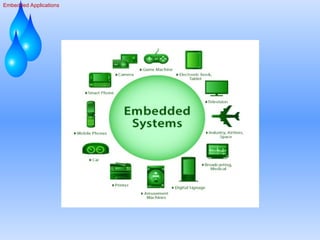
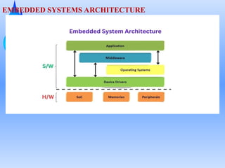
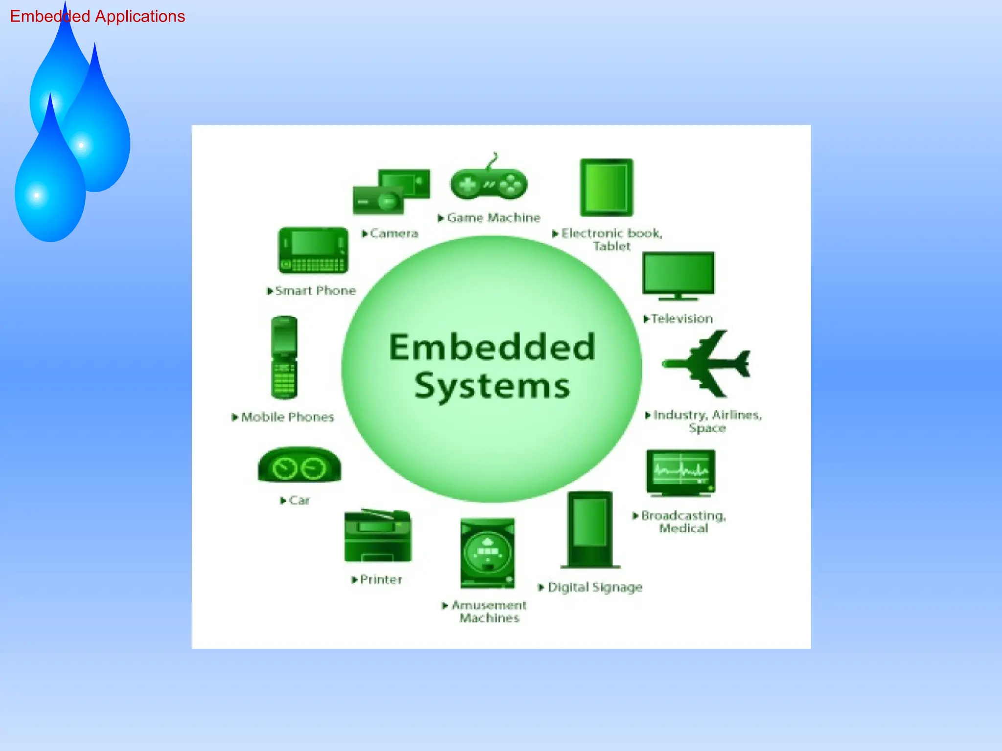
In the imageabove, the concept of embedded systems is
explained. Embedded systems are the integration of hardware and
software. Let’s delve into this further.
Hardware (H/W)
In embedded systems, hardware refers to the combination of
electrical and electronic components, including the processor. The
processor itself embodies both hardware and software functionalities.
It’s an integrated circuit (IC) designed by hardware engineers, capable of
executing programs or software stored in memory.
Different components of Processor hardware:
System on Chip (SoC): The SoC integrates all components of a
computer or electronic system into a single chip. It includes the CPU,
memory, input/output ports, and other essential components, making it a
compact and efficient solution for embedded systems.
7.
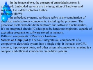
Memories: This refersto storage components like RAM
(Random Access Memory) and ROM (Read-Only Memory). RAM is
used for temporary data storage and quick access, while ROM stores
firmware and other permanent data.
Peripherals: Peripherals are external devices connected to the system,
such as sensors, actuators, displays, and communication modules. They
extend the system’s capabilities and allow it to interact with the external
environment.
8.
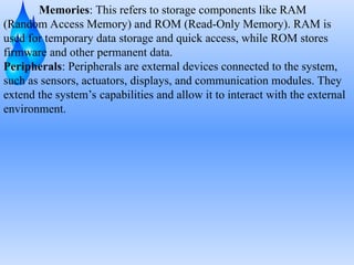
Software (S/W)
Software (S/W)refers to a collection of instructions, programs, or data
that directs a computer or embedded system on how to perform specific
tasks or operations. It encompasses applications, operating systems,
utilities, and other programs that enable the functionality of hardware
devices and systems.
Different components of Software used in Embedded Systems are
explained below:
Application
The Application layer represents the high-level software designed to
perform specific tasks for the user. This could be anything from a simple
user interface to complex data processing algorithms. Applications are
what users interact with directly, making them crucial for the system’s
functionality.
9.
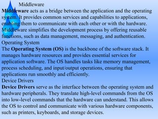
Middleware
Middleware acts asa bridge between the application and the operating
system. It provides common services and capabilities to applications,
enabling them to communicate with each other or with the hardware.
Middleware simplifies the development process by offering reusable
functions, such as data management, messaging, and authentication.
Operating System
The Operating System (OS) is the backbone of the software stack. It
manages hardware resources and provides essential services for
application software. The OS handles tasks like memory management,
process scheduling, and input/output operations, ensuring that
applications run smoothly and efficiently.
Device Drivers
Device Drivers serve as the interface between the operating system and
hardware peripherals. They translate high-level commands from the OS
into low-level commands that the hardware can understand. This allows
the OS to control and communicate with various hardware components,
such as printers, keyboards, and storage devices.
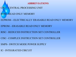
ABBREVIATIONS
CPU—CENTRAL PROCESSING UNIT
ROM–READ ONLY MEMORY
EEPROM—ELECTRICALLY ERASABLE READ ONLY MEMORY
EPROM—ERASABLE READ ONLY MEMORY
RISC– REDUCED INSTRUCTION SET CONTROLLER
CISC– COMPLEX INSTRUCTION SET CONTROLLER
SMPS– SWITCH MODE POWER SUPPLY
IC– INTEGRATED CIRCUIT
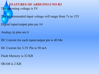
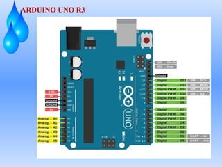
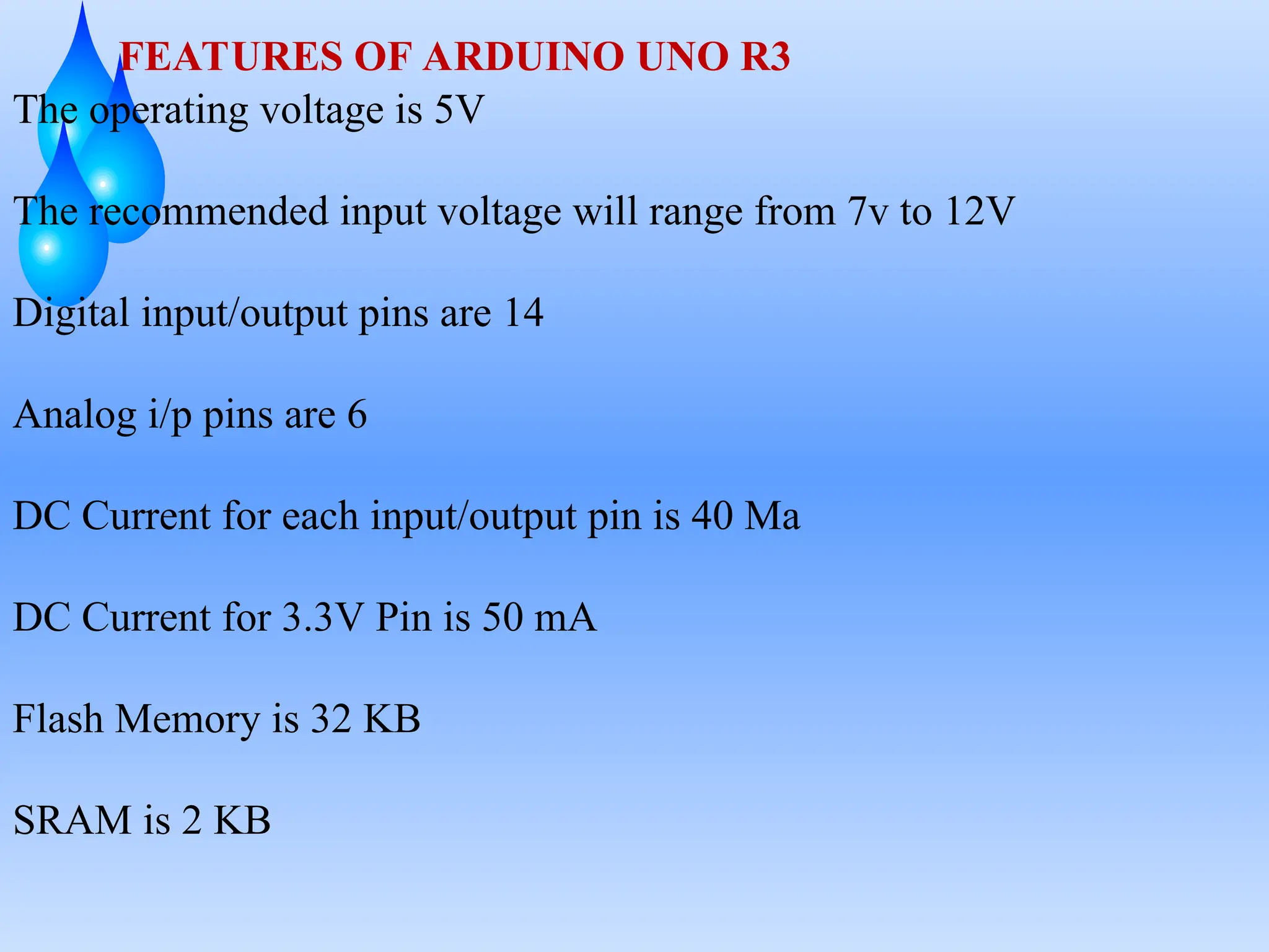
FEATURES OF ARDUINOUNO R3
The operating voltage is 5V
The recommended input voltage will range from 7v to 12V
Digital input/output pins are 14
Analog i/p pins are 6
DC Current for each input/output pin is 40 Ma
DC Current for 3.3V Pin is 50 mA
Flash Memory is 32 KB
SRAM is 2 KB
19.
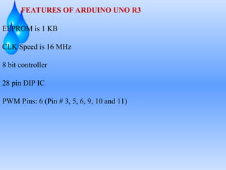
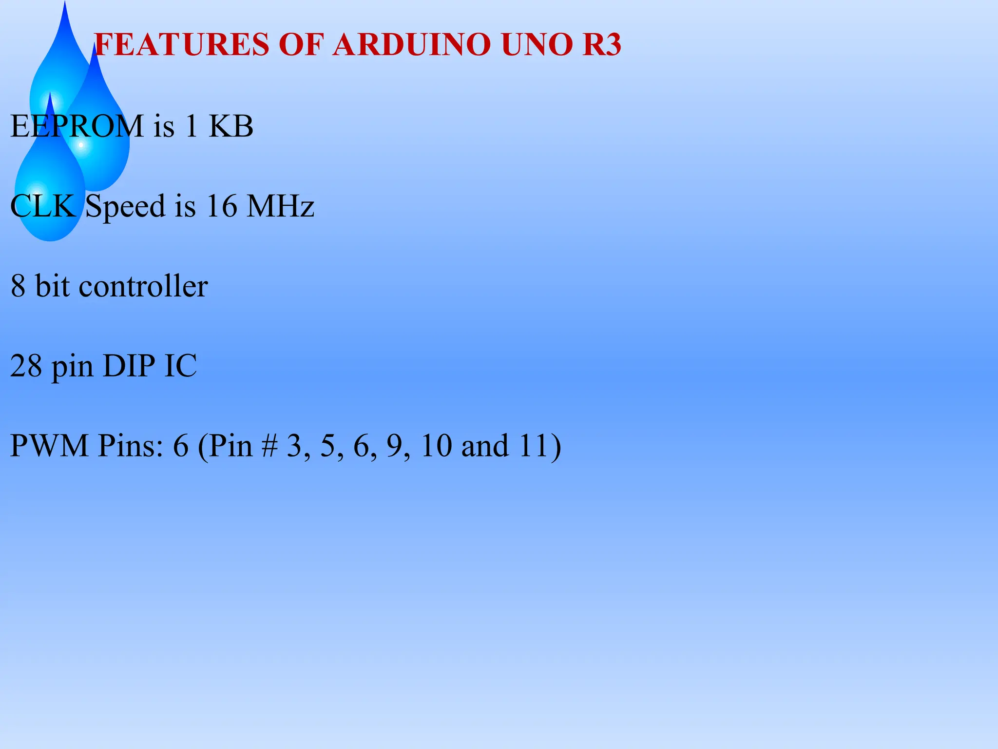
FEATURES OF ARDUINOUNO R3
EEPROM is 1 KB
CLK Speed is 16 MHz
8 bit controller
28 pin DIP IC
PWM Pins: 6 (Pin # 3, 5, 6, 9, 10 and 11)
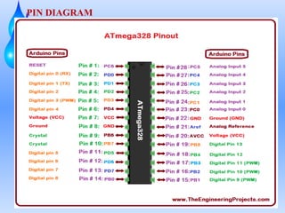
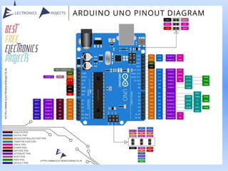
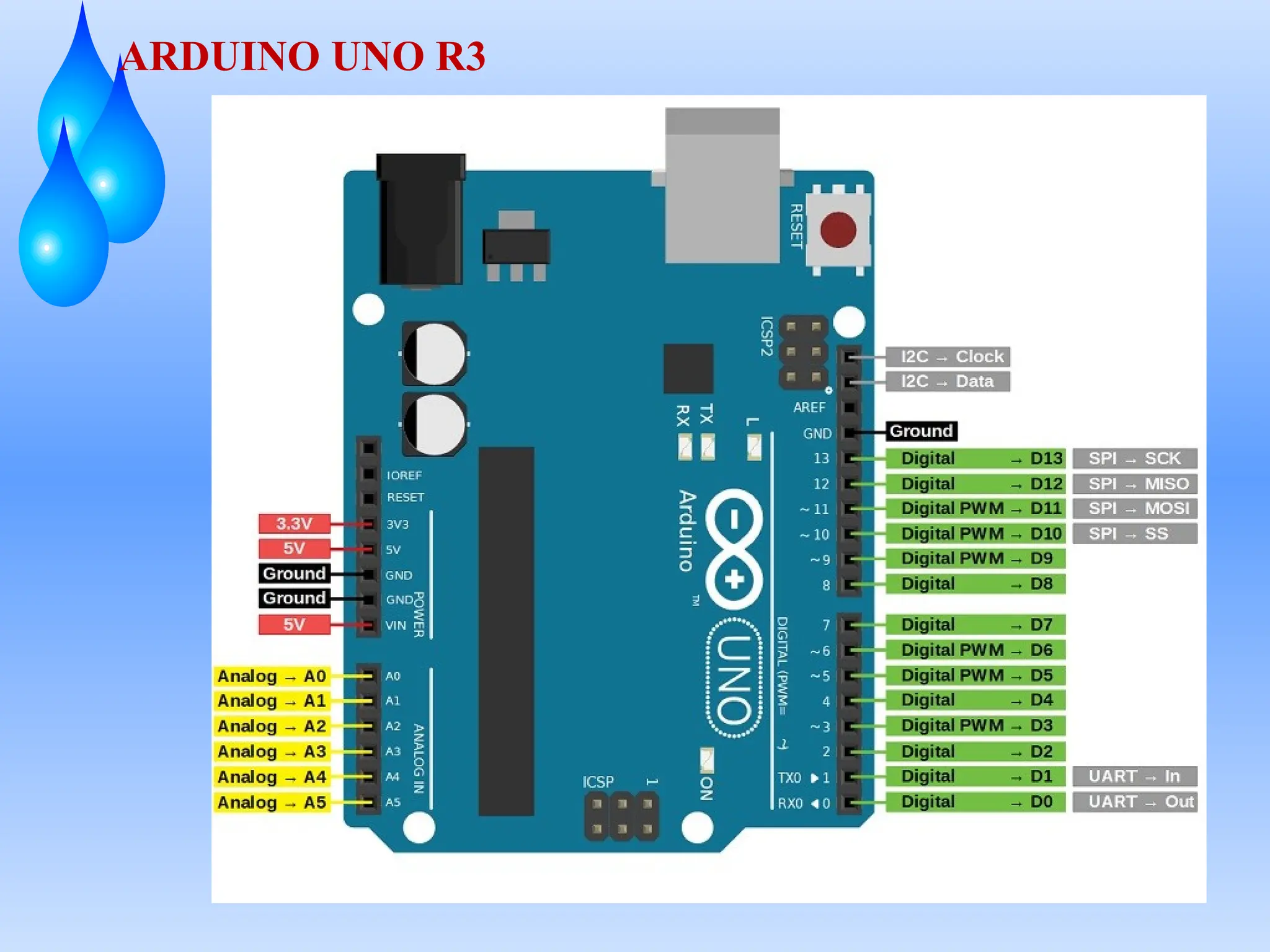
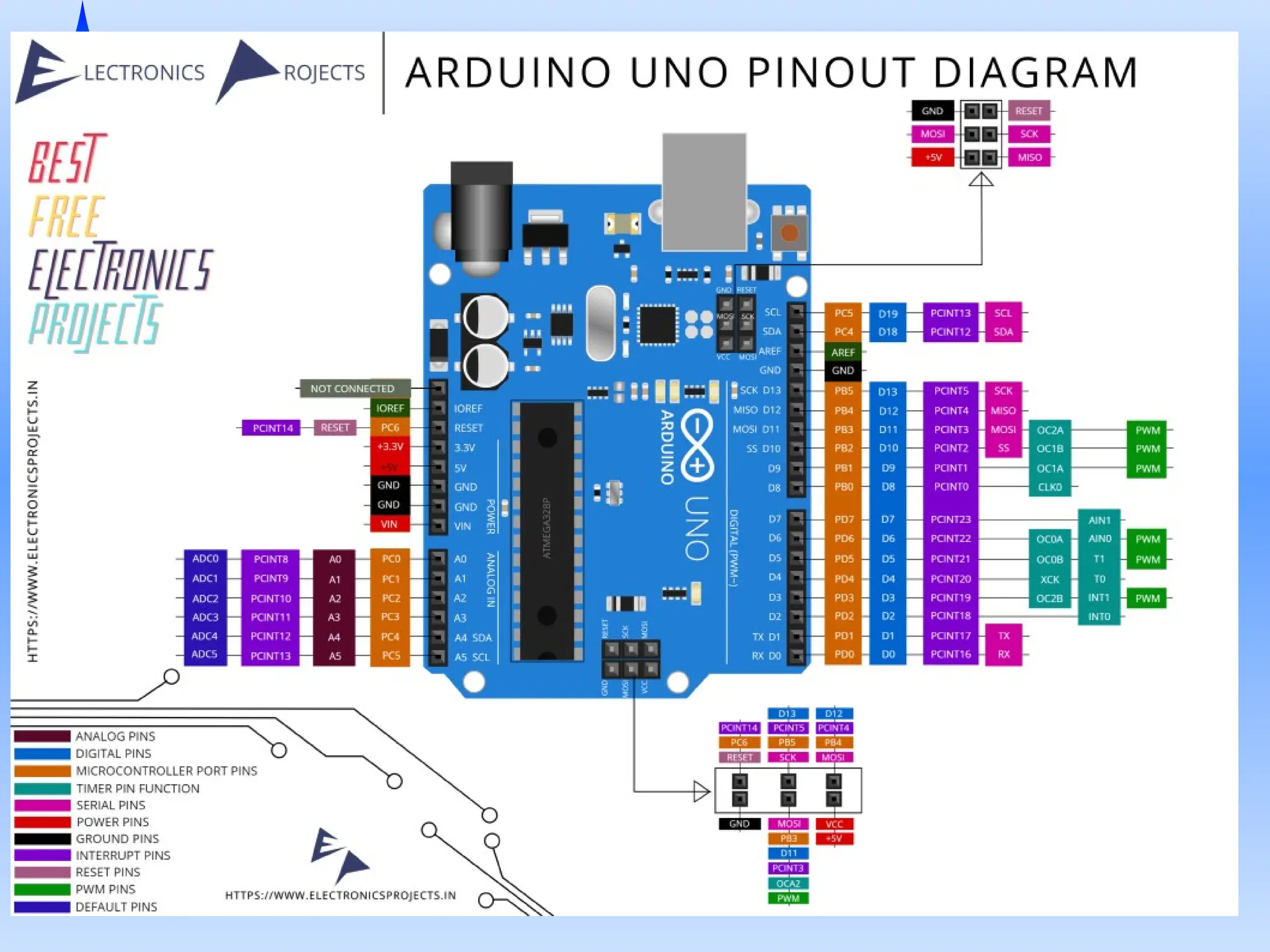
Vin: This isthe input voltage pin of the Arduino board used to provide
input supply from an external power source.
5V: This pin of the Arduino board is used as a regulated power supply
voltage and it is used to give supply to the board as well as onboard
components.
3.3V: This pin of the board is used to provide a supply of 3.3V which is
generated from a voltage regulator on the board
GND: This pin of the board is used to ground the Arduino board.
Reset: This pin of the board is used to reset the microcontroller. It is
used to Resets the microcontroller.
Analog Pins: The pins A0 to A5 are used as an analog input and it is in
the range of 0-5V.
23.
Digital Pins: Thepins 0 to 13 are used as a digital input or output for the
Arduino board.
Serial Pins: These pins are also known as a UART pin. It is used for
communication between the Arduino board and a computer or other
devices. The transmitter pin number 1 and receiver pin number 0 is used
to transmit and receive the data resp.
Set baud rate and begin serial port
Serial.begin(baudrate);
Ex: Serial.begin(9600);
if(Serial.available())-- // if there is data coming
Serial.print("ArduinoGetStarted.com");
Serial.println(); // print an empty line
Serial.println("ArduinoGetStarted.com");
External Interrupt Pins:This pin of the Arduino board is used to
produce the External interrupt and it is done by pin numbers 2 and 3.
PWM Pins: This pins of the board is used to convert the digital signal
into an analog by varying the width of the Pulse. The pin numbers
3,5,6,9,10 and 11 are used as a PWM pin.
SPI Pins: This is the Serial Peripheral Interface pin, it is used to
maintain SPI communication with the help of the SPI library. SPI pins
include:
SS: Pin number 10 is used as a Slave Select
MOSI: Pin number 11 is used as a Master Out Slave In
MISO: Pin number 12 is used as a Master In Slave Out
SCK: Pin number 13 is used as a Serial Clock
LED Pin: The board has an inbuilt LED using digital pin-13. The LED
glows only when the digital pin becomes high.
26.
AREF Pin: Thisis an analog reference pin of the Arduino board. It is
used to provide a reference voltage from an external power supply.
27.
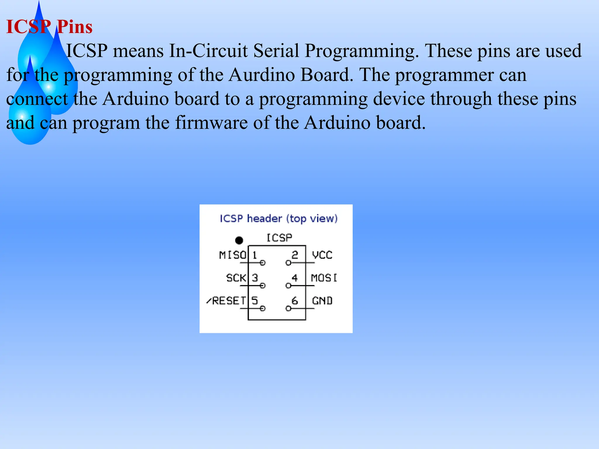
ICSP Pins
ICSP meansIn-Circuit Serial Programming. These pins are used
for the programming of the Aurdino Board. The programmer can
connect the Arduino board to a programming device through these pins
and can program the firmware of the Arduino board.
29.
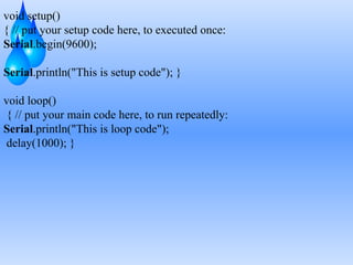
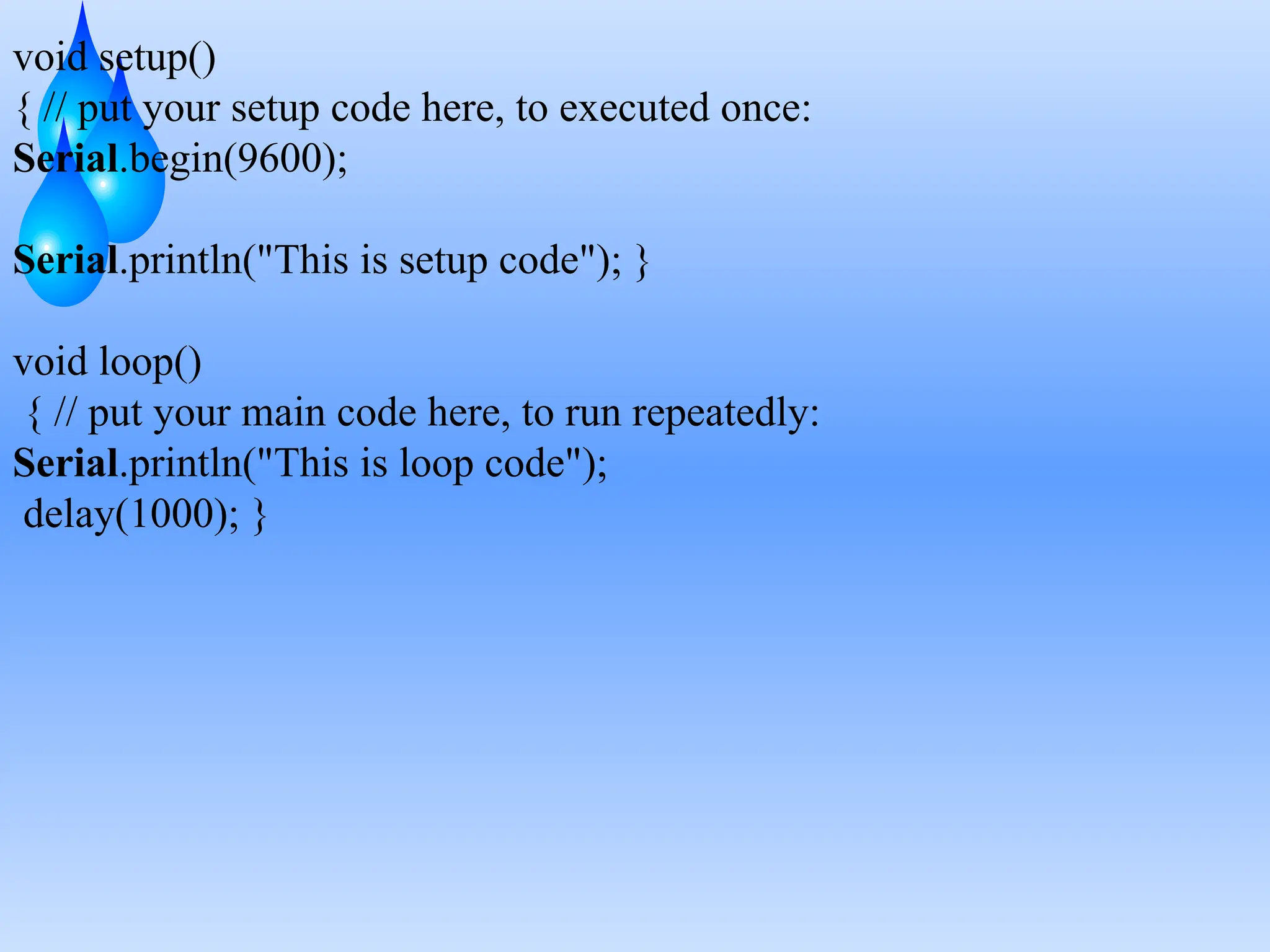
void setup()
{ //put your setup code here, to executed once:
Serial.begin(9600);
Serial.println("This is setup code"); }
void loop()
{ // put your main code here, to run repeatedly:
Serial.println("This is loop code");
delay(1000); }
31.
.
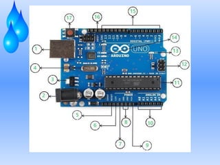
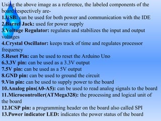
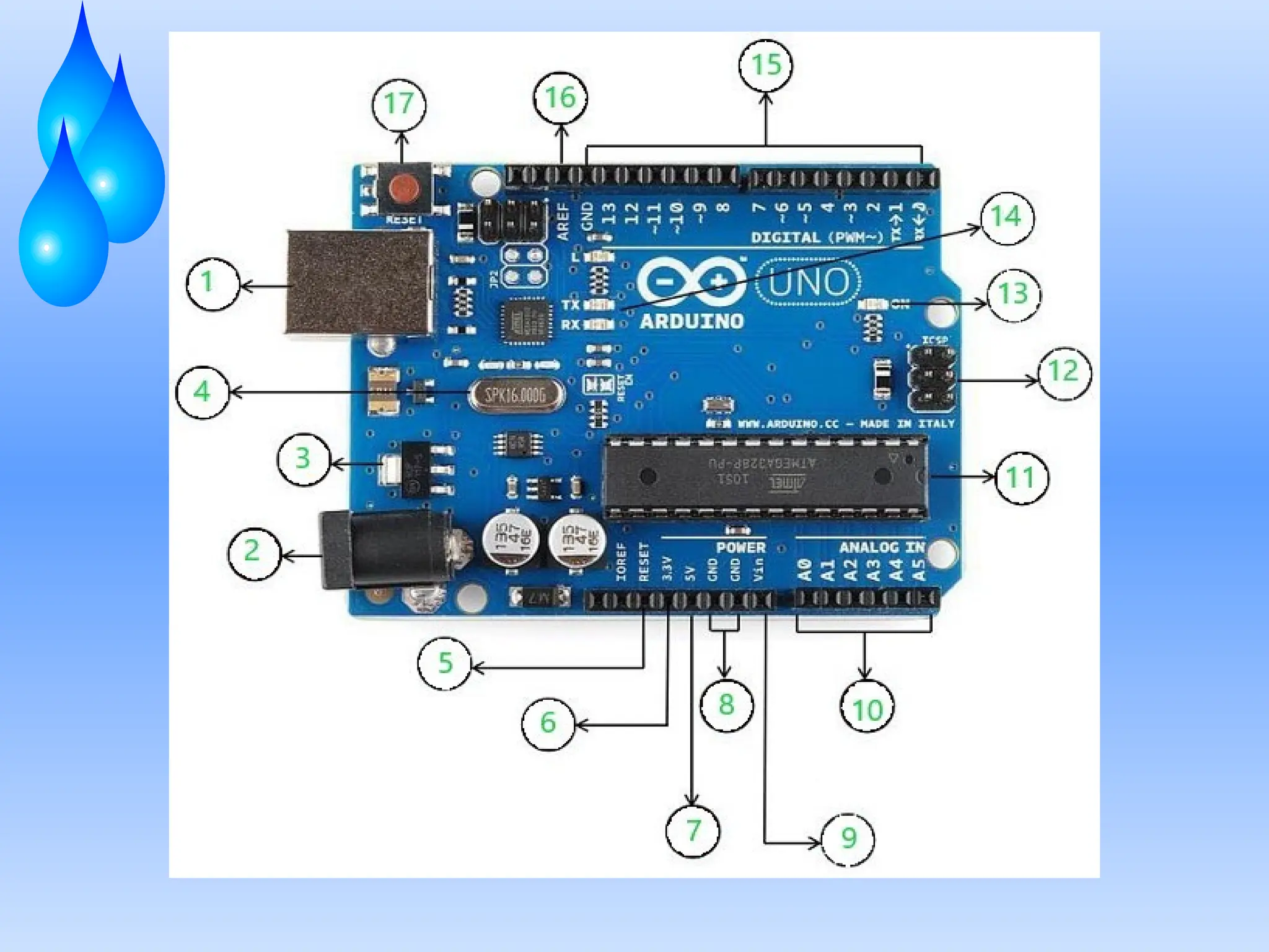
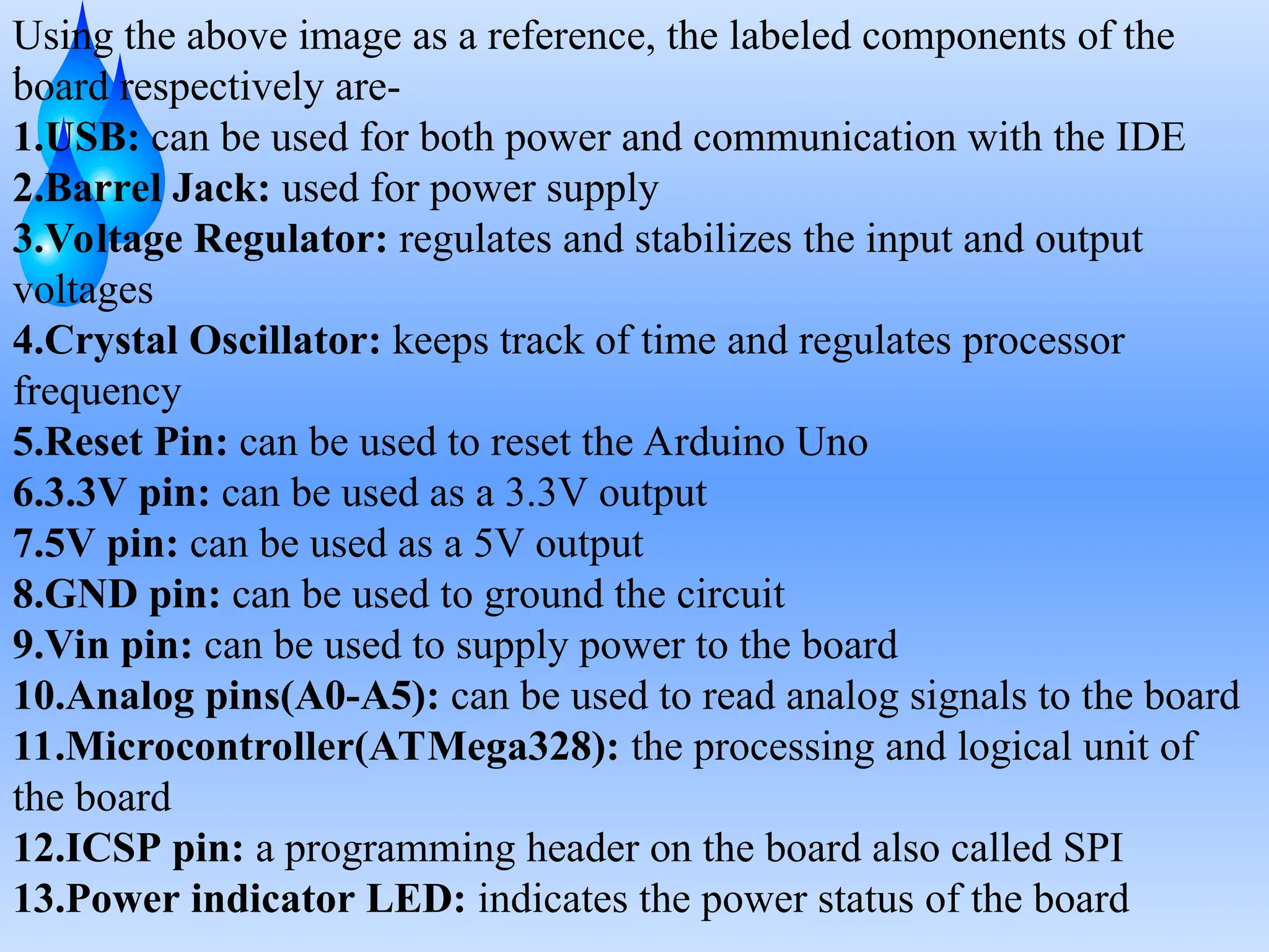
Using the aboveimage as a reference, the labeled components of the
board respectively are-
1.USB: can be used for both power and communication with the IDE
2.Barrel Jack: used for power supply
3.Voltage Regulator: regulates and stabilizes the input and output
voltages
4.Crystal Oscillator: keeps track of time and regulates processor
frequency
5.Reset Pin: can be used to reset the Arduino Uno
6.3.3V pin: can be used as a 3.3V output
7.5V pin: can be used as a 5V output
8.GND pin: can be used to ground the circuit
9.Vin pin: can be used to supply power to the board
10.Analog pins(A0-A5): can be used to read analog signals to the board
11.Microcontroller(ATMega328): the processing and logical unit of
the board
12.ICSP pin: a programming header on the board also called SPI
13.Power indicator LED: indicates the power status of the board
32.
.
14.RX and TXLEDs: receive(RX) and transmit(TX) LEDs, blink when
sending or receiving serial data respectively
15.Digital I/O pins: 14 pins capable of reading and outputting digital
signals; 6 of these pins are also capable of PWM
16.AREF pins: can be used to set an external reference voltage as the
upper limit for the analog pins
17.Reset button: can be used to reset the board
.
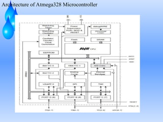
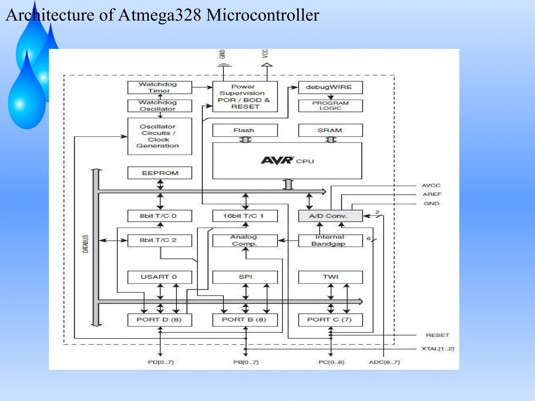
CPU ( CentralProcessing Unit )
An 8-bit CPU at the heart of the microcontroller executes commands
extremely well. It has a wide range of registers, enabling flexible data
manipulation and control flow.
Memory
Program Memory: The CPU fetches and executes the programme code
that is stored in the flash memory. Even complicated programmes can be
supported by the 32KB capacity.
Data Memory: SRAM and EEPROM are the two forms of data memory
used by the ATmega328P. While EEPROM offers non-volatile storage
for crucial data that must endure through power cycles, SRAM offers
volatile data storage.
Input/Output Ports
The microcontroller’s interface with the outside world is represented via
its pins. These pins can be set up as inputs or outputs, which enables a
variety of uses, including reading sensors and driving LEDs.
35.
.
Timers and Counters
Inmany embedded systems, precise timing is essential. Three timers are
available on the ATmega328P, each with special qualities that make
them useful for different applications. These timers are frequently used
to produce precise PWM signals to control motors, among other things.
Communication Module ( USART )
By enabling serial communication, the USART modules allow for
communication with external hardware, including sensors, displays, and
other microcontrollers.
Analog to Digital Converter
For situations where the transformation of analogue signals into digital
data is necessary, the ADC is an invaluable component. Sensor
interfacing and data gathering systems frequently make advantage of this
functionality.