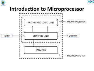
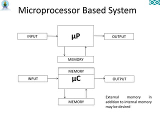
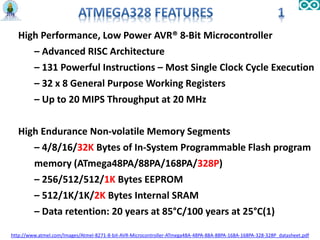
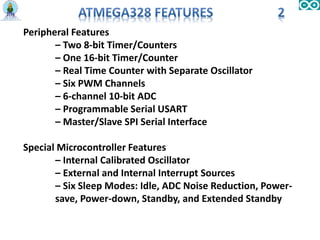
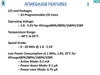
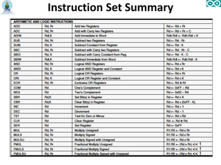
The document provides a comprehensive overview of microprocessors and microcontrollers, particularly focusing on the 8051 microcontroller and Arduino platform. It includes details on architecture, instruction sets, and programming interfaces, as well as comparisons between microprocessor and microcontroller features. Additionally, it highlights the advantages of Arduino, examples of projects, and the basics of Arduino programming.
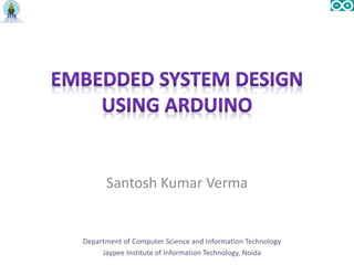
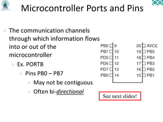
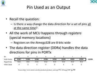
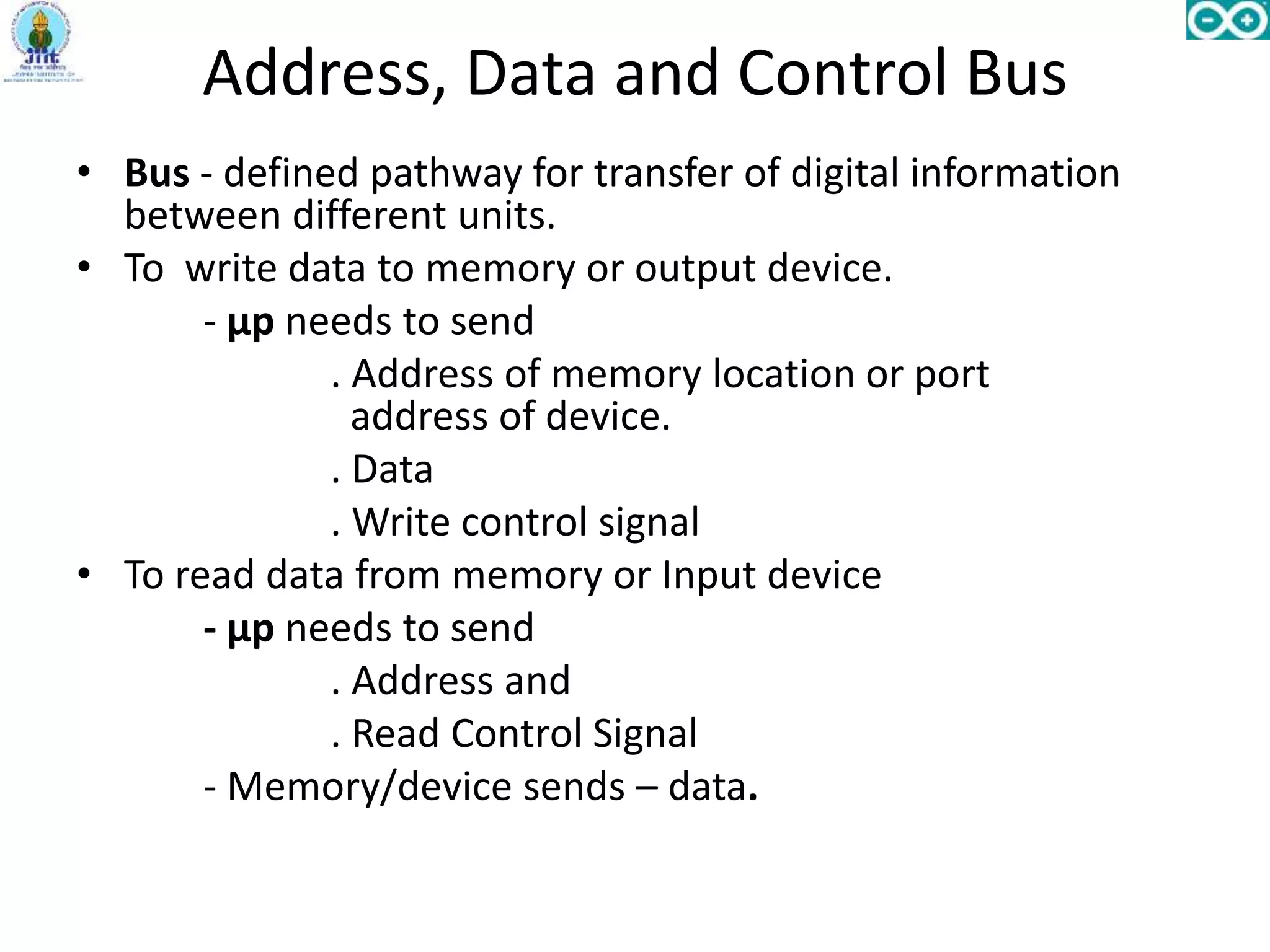
![Thus three pathways (buses) for 3 types of digital
information.
Address Bus - From µp to devices
- Unidirectional.
Data Bus - From µp to devices & devices to µp
- Bidirectional
Control - From µp to devices & from devices to µp
[Interrupt, DMA]
- Bidirectional
Now let us redraw the computer organization diagram](https://image.slidesharecdn.com/embeddedsystemdesignusingarduino-161008064345/85/Embedded-system-design-using-arduino-8-320.jpg)
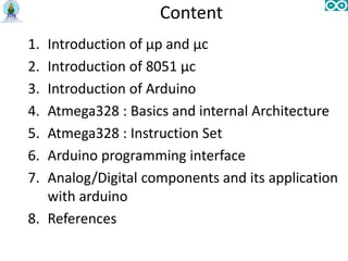
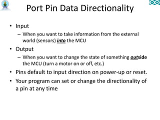
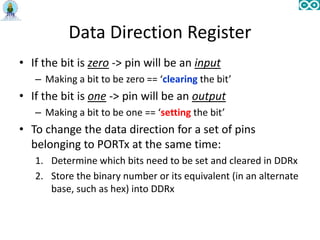
![Microcontroller
A microcontroller is a complete computer system, including
a CPU, memory, a clock oscillator, and I/O on a single
integrated circuit chip. [1]
ANALOG
INPUTS
http://www.freescale.com/files/microcontrollers/doc/ref_manual/M68HC05TB.pdf, p. 25](https://image.slidesharecdn.com/embeddedsystemdesignusingarduino-161008064345/85/Embedded-system-design-using-arduino-10-320.jpg)
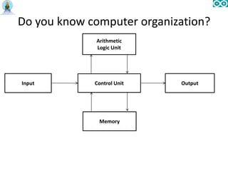
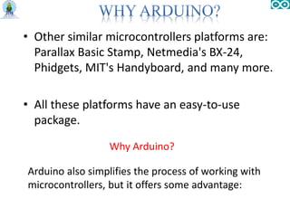
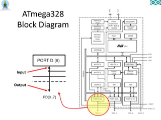
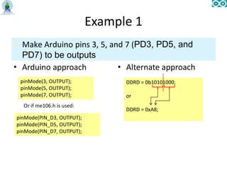
![• Introduced in 2005 as a project for students at the Interaction Design
Institute Ivrea in Ivrea, Italy, Arduino is a single board microcontroller.
• An Arduino board consists of an Atmel 8-bit AVR microcontroller with
complementary components to facilitate programming and incorporation
into other circuits [2].
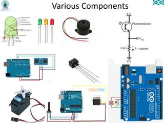
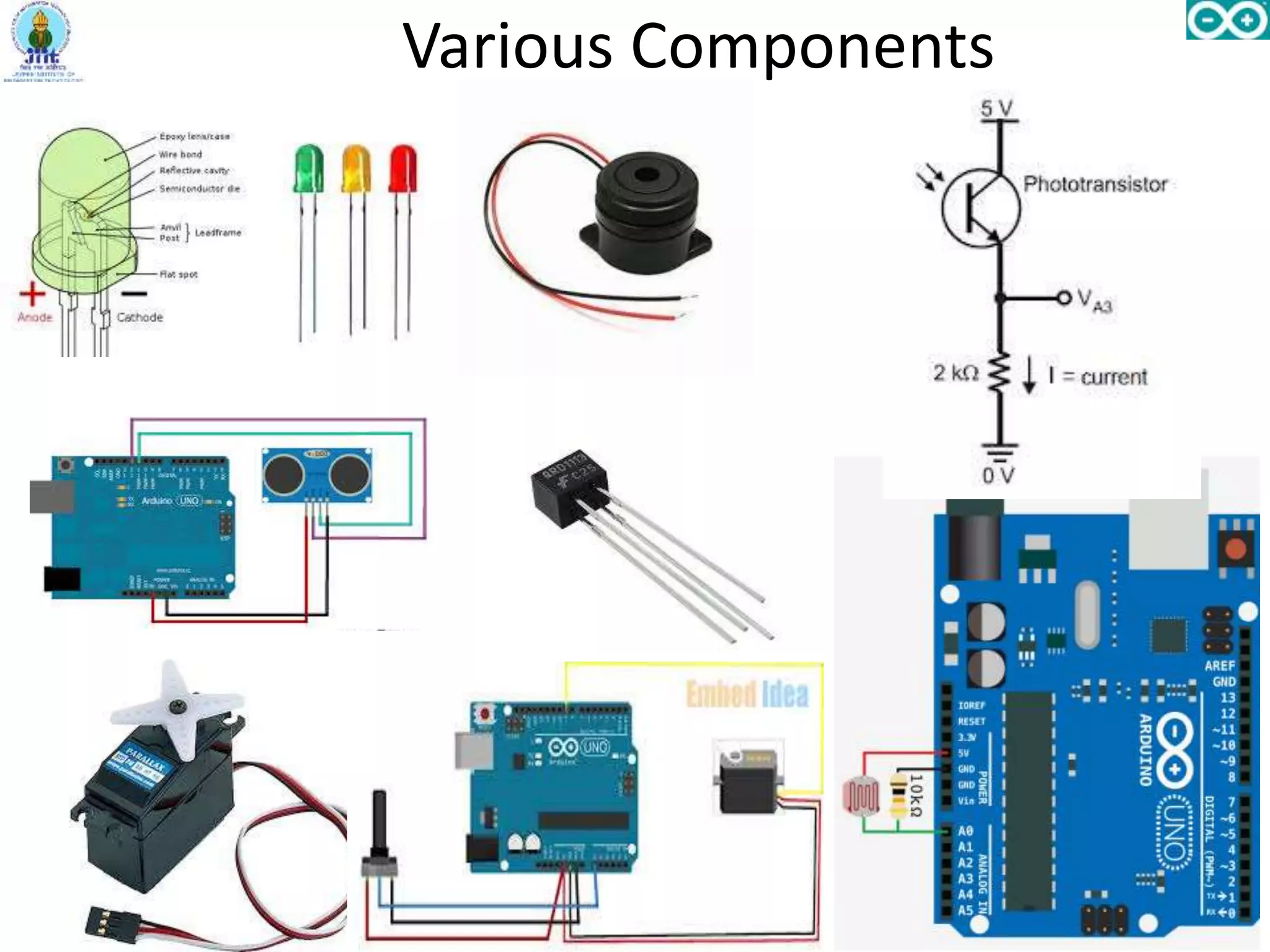
• Arduino can sense the environment by receiving input from a variety of
sensors and can affect its surroundings by controlling lights, motors, and
other actuators.
• The boards can be assembled or purchased preassembled; the open-source
IDE can be downloaded for free.
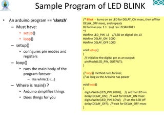
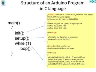
• The Arduino programming language is very simple and follows C like
syntax.
• Arduino projects can be stand-alone or they can communicate with
software running on a computer (e.g. Processing).](https://image.slidesharecdn.com/embeddedsystemdesignusingarduino-161008064345/85/Embedded-system-design-using-arduino-15-320.jpg)

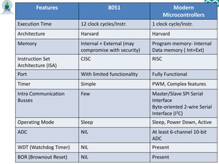

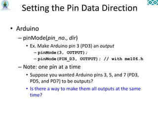

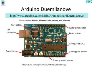

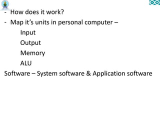
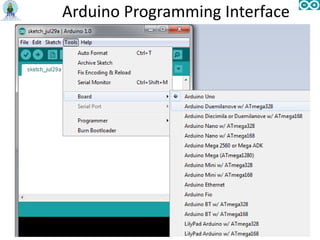
![• The Arduino Duemilanove can be programmed with the
Arduino software.
• The Arduino integrated development environment (IDE) is
written in Java, and is derived from the IDE for the
Processing programming language.
• It includes a code editor with features such as syntax
highlighting, brace matching, and automatic indentation,
and is also capable of compiling and uploading programs
to the board with a single click. A program or code written
for Arduino is called a "sketch".[3]
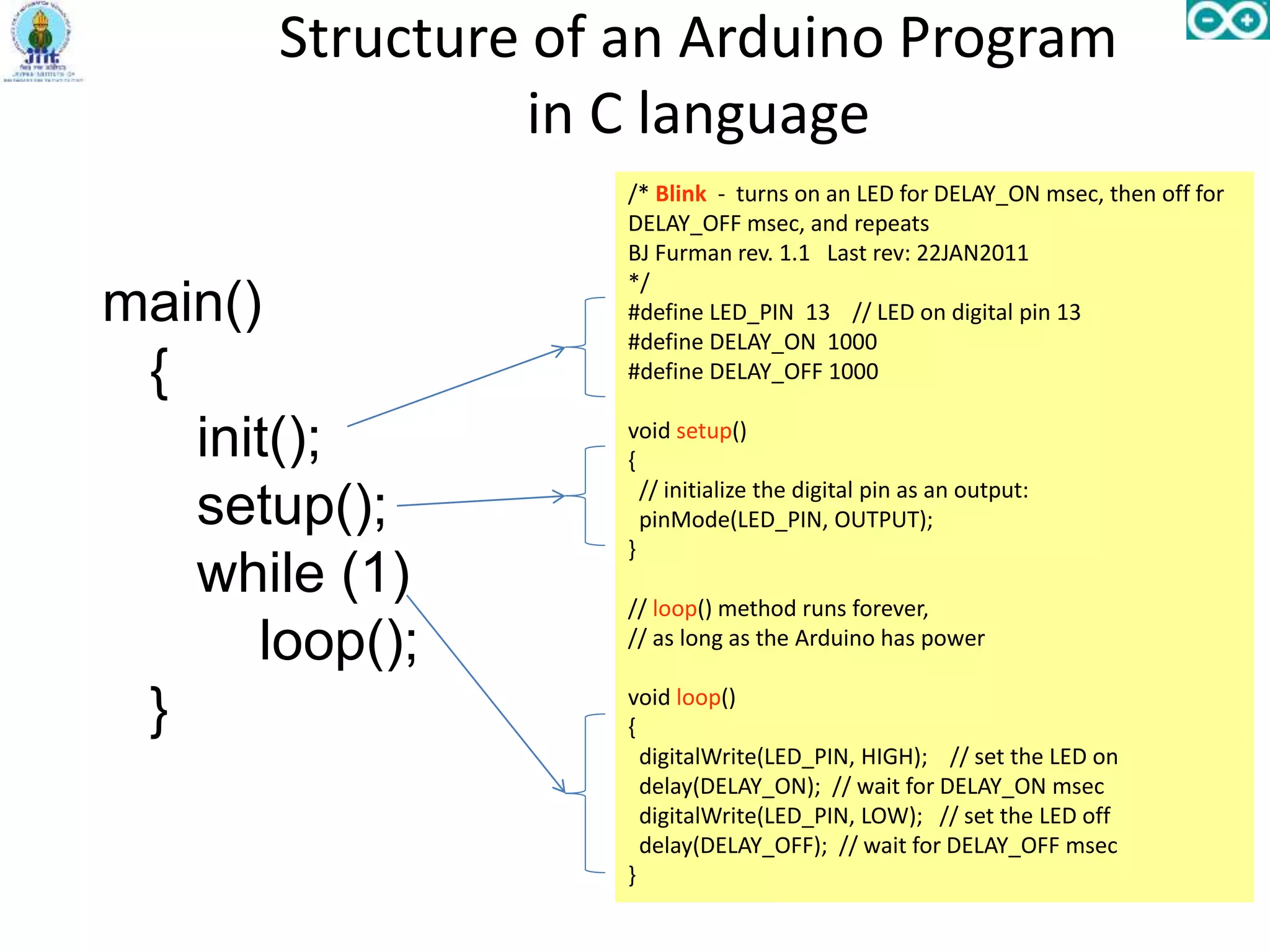
• Arduino programs are written in C or C++.
About Arduino Programming](https://image.slidesharecdn.com/embeddedsystemdesignusingarduino-161008064345/85/Embedded-system-design-using-arduino-44-320.jpg)

![1. http://www.freescale.com/files/microcontrollers/doc/ref_manual/M68HC0
5TB.pdf, p. 25
2. Arduino, “Avalable at http://www.arduino.cc,” 2010.
3. "Programming Arduino Getting Started with Sketches“ :
http://www.amazon.com/Programming-Arduino-Getting-Started-
Sketches/dp/0071784225/ref=sr_1_1?s=books&ie=UTF8&qid=136449413
8&sr=1-1&keywords=arduino+sketches). McGraw-Hill. Nov 8, 2011.
Retrieved 2013-03-28.
4. C. L. Dym, A. M. Agogino, D. D. Frey, and L. J. Leifer, “Engineering
design thinking, teaching, and learning,” Journal of Engineering
Education, vol. 94, pp. 103–120, 2005. [Online]. Available:
http://citeseerx.ist.psu.edu/viewdoc/summary?doi=10.1.1.72.1593
5. http://www.atmel.com/dyn/products/product_card.asp?PN=ATmega328
6. J. Provost, “Why the arduino won and why it’s here to stay,” Tech.Rep.
7. http://learn.adafruit.com/arduino-tips-tricks-and-techniques/arduino-uno-
faq](https://image.slidesharecdn.com/embeddedsystemdesignusingarduino-161008064345/85/Embedded-system-design-using-arduino-51-320.jpg)


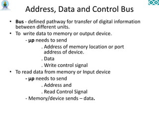
![Thus three pathways (buses) for 3 types of digital
information.
Address Bus - From µp to devices
- Unidirectional.
Data Bus - From µp to devices & devices to µp
- Bidirectional
Control - From µp to devices & from devices to µp
[Interrupt, DMA]
- Bidirectional
Now let us redraw the computer organization diagram](https://image.slidesharecdn.com/embeddedsystemdesignusingarduino-161008064345/75/Embedded-system-design-using-arduino-8-2048.jpg)

![Microcontroller
A microcontroller is a complete computer system, including
a CPU, memory, a clock oscillator, and I/O on a single
integrated circuit chip. [1]
ANALOG
INPUTS
http://www.freescale.com/files/microcontrollers/doc/ref_manual/M68HC05TB.pdf, p. 25](https://image.slidesharecdn.com/embeddedsystemdesignusingarduino-161008064345/75/Embedded-system-design-using-arduino-10-2048.jpg)

![• Introduced in 2005 as a project for students at the Interaction Design
Institute Ivrea in Ivrea, Italy, Arduino is a single board microcontroller.
• An Arduino board consists of an Atmel 8-bit AVR microcontroller with
complementary components to facilitate programming and incorporation
into other circuits [2].
• Arduino can sense the environment by receiving input from a variety of
sensors and can affect its surroundings by controlling lights, motors, and
other actuators.
• The boards can be assembled or purchased preassembled; the open-source
IDE can be downloaded for free.
• The Arduino programming language is very simple and follows C like
syntax.
• Arduino projects can be stand-alone or they can communicate with
software running on a computer (e.g. Processing).](https://image.slidesharecdn.com/embeddedsystemdesignusingarduino-161008064345/75/Embedded-system-design-using-arduino-15-2048.jpg)


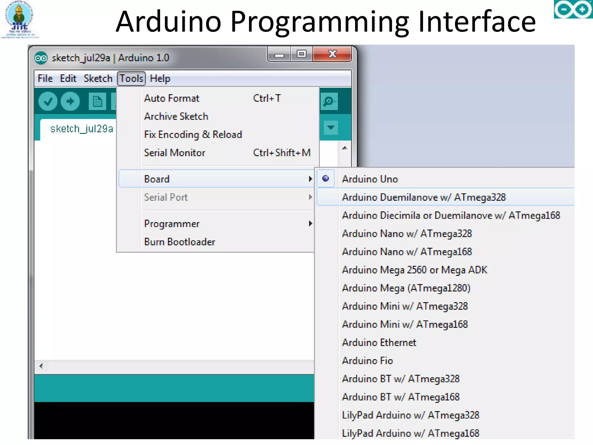
![• The Arduino Duemilanove can be programmed with the
Arduino software.
• The Arduino integrated development environment (IDE) is
written in Java, and is derived from the IDE for the
Processing programming language.
• It includes a code editor with features such as syntax
highlighting, brace matching, and automatic indentation,
and is also capable of compiling and uploading programs
to the board with a single click. A program or code written
for Arduino is called a "sketch".[3]
• Arduino programs are written in C or C++.
About Arduino Programming](https://image.slidesharecdn.com/embeddedsystemdesignusingarduino-161008064345/75/Embedded-system-design-using-arduino-44-2048.jpg)
![1. http://www.freescale.com/files/microcontrollers/doc/ref_manual/M68HC0
5TB.pdf, p. 25
2. Arduino, “Avalable at http://www.arduino.cc,” 2010.
3. "Programming Arduino Getting Started with Sketches“ :
http://www.amazon.com/Programming-Arduino-Getting-Started-
Sketches/dp/0071784225/ref=sr_1_1?s=books&ie=UTF8&qid=136449413
8&sr=1-1&keywords=arduino+sketches). McGraw-Hill. Nov 8, 2011.
Retrieved 2013-03-28.
4. C. L. Dym, A. M. Agogino, D. D. Frey, and L. J. Leifer, “Engineering
design thinking, teaching, and learning,” Journal of Engineering
Education, vol. 94, pp. 103–120, 2005. [Online]. Available:
http://citeseerx.ist.psu.edu/viewdoc/summary?doi=10.1.1.72.1593
5. http://www.atmel.com/dyn/products/product_card.asp?PN=ATmega328
6. J. Provost, “Why the arduino won and why it’s here to stay,” Tech.Rep.
7. http://learn.adafruit.com/arduino-tips-tricks-and-techniques/arduino-uno-
faq](https://image.slidesharecdn.com/embeddedsystemdesignusingarduino-161008064345/75/Embedded-system-design-using-arduino-51-2048.jpg)


![Introduction to ESP32 Programming [Road to RIoT 2017]](https://cdn.slidesharecdn.com/ss_thumbnails/roadtoriotsurabayagettingstartedesp32-170726155154-thumbnail.jpg?width=600ounds&width=560&fit=bounds)


