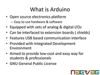
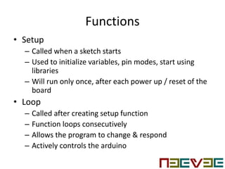
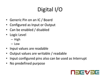
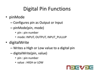
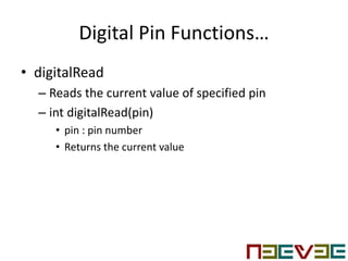
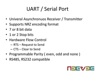
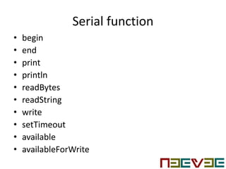
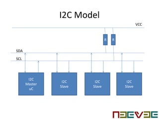
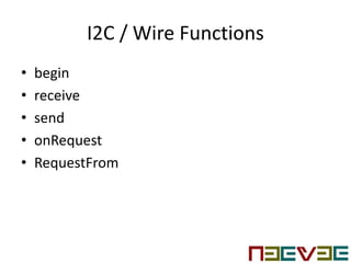
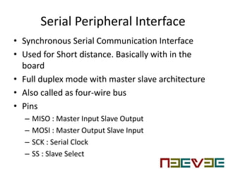
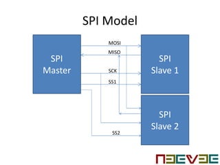
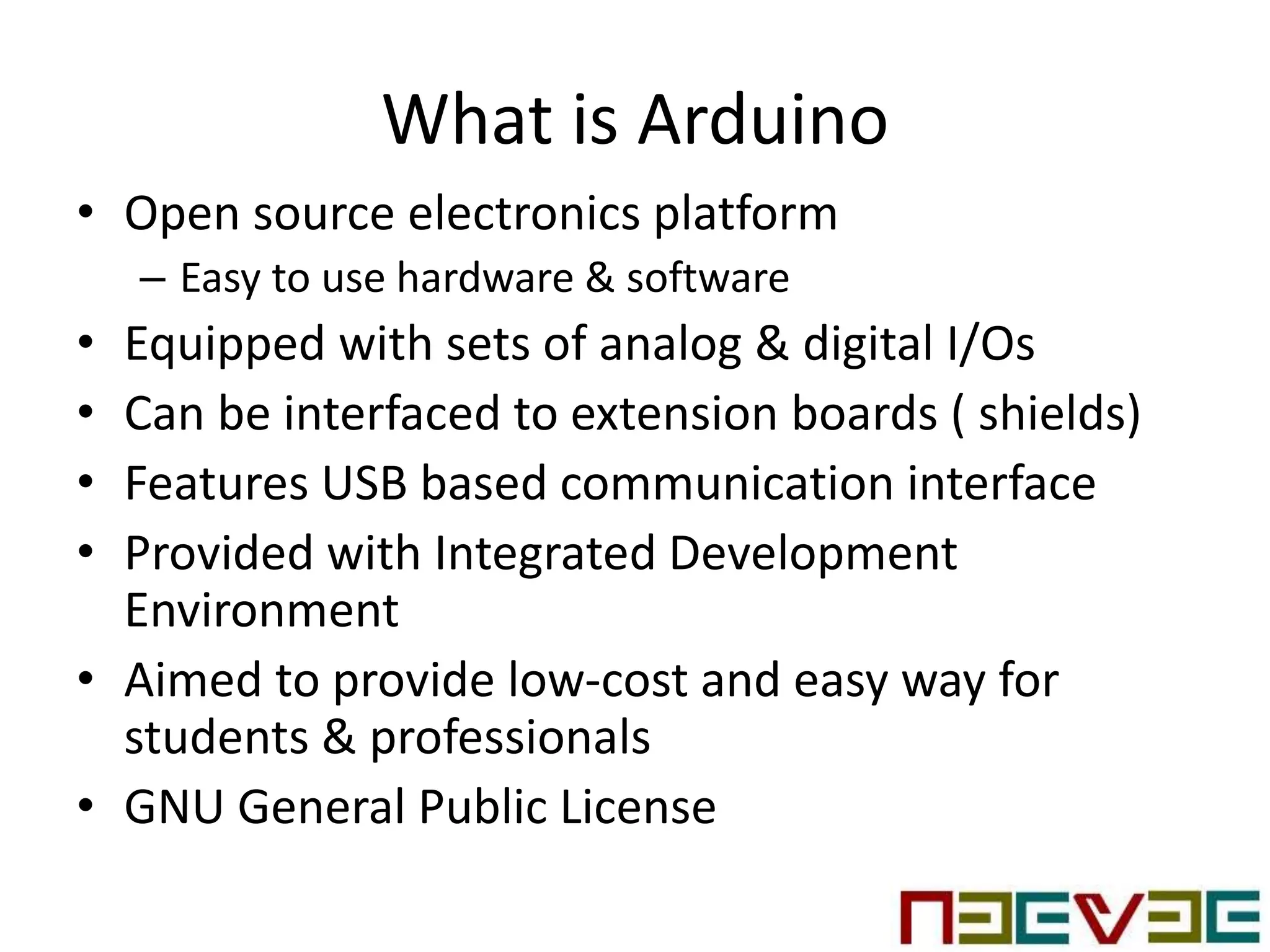
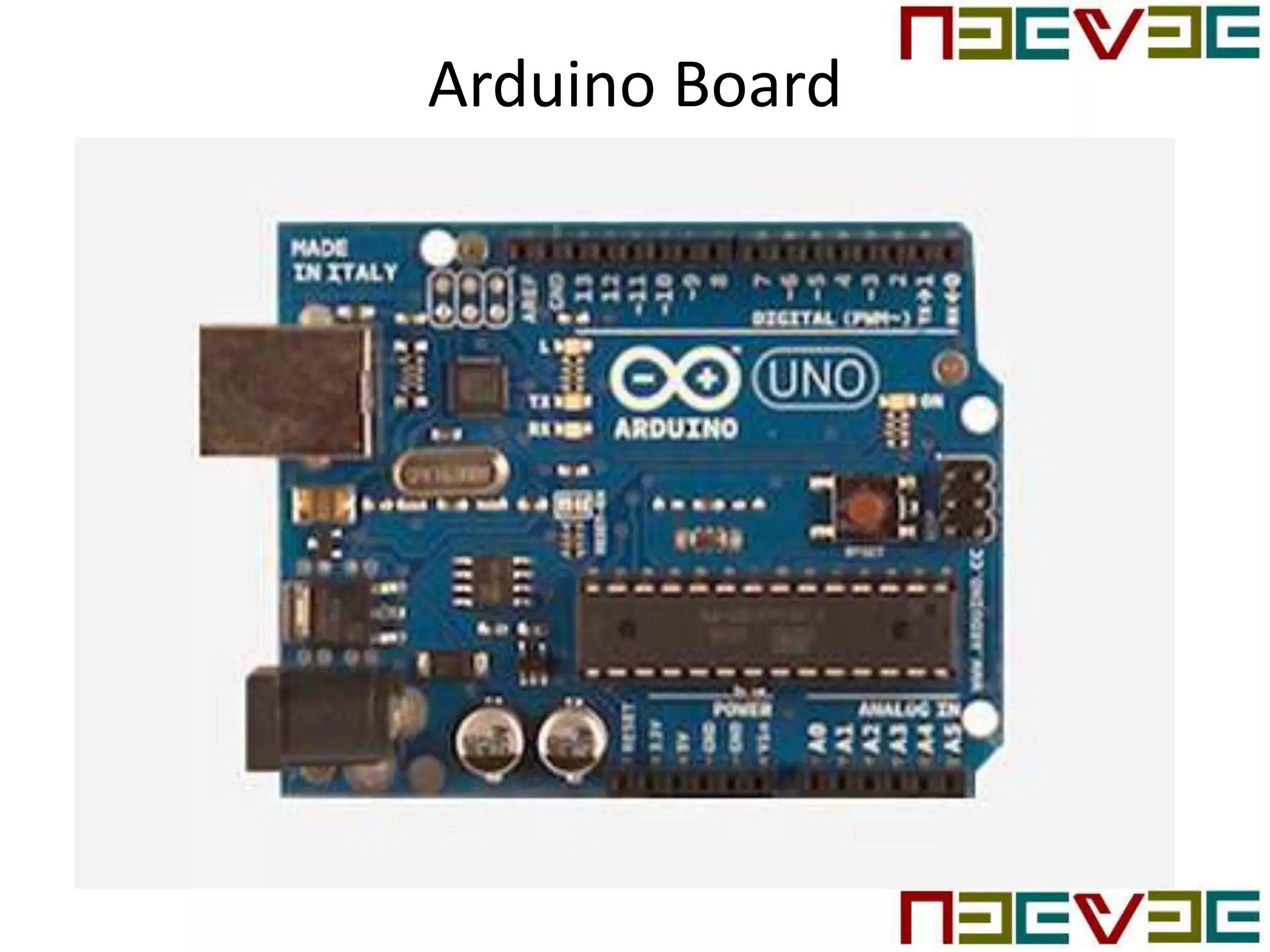
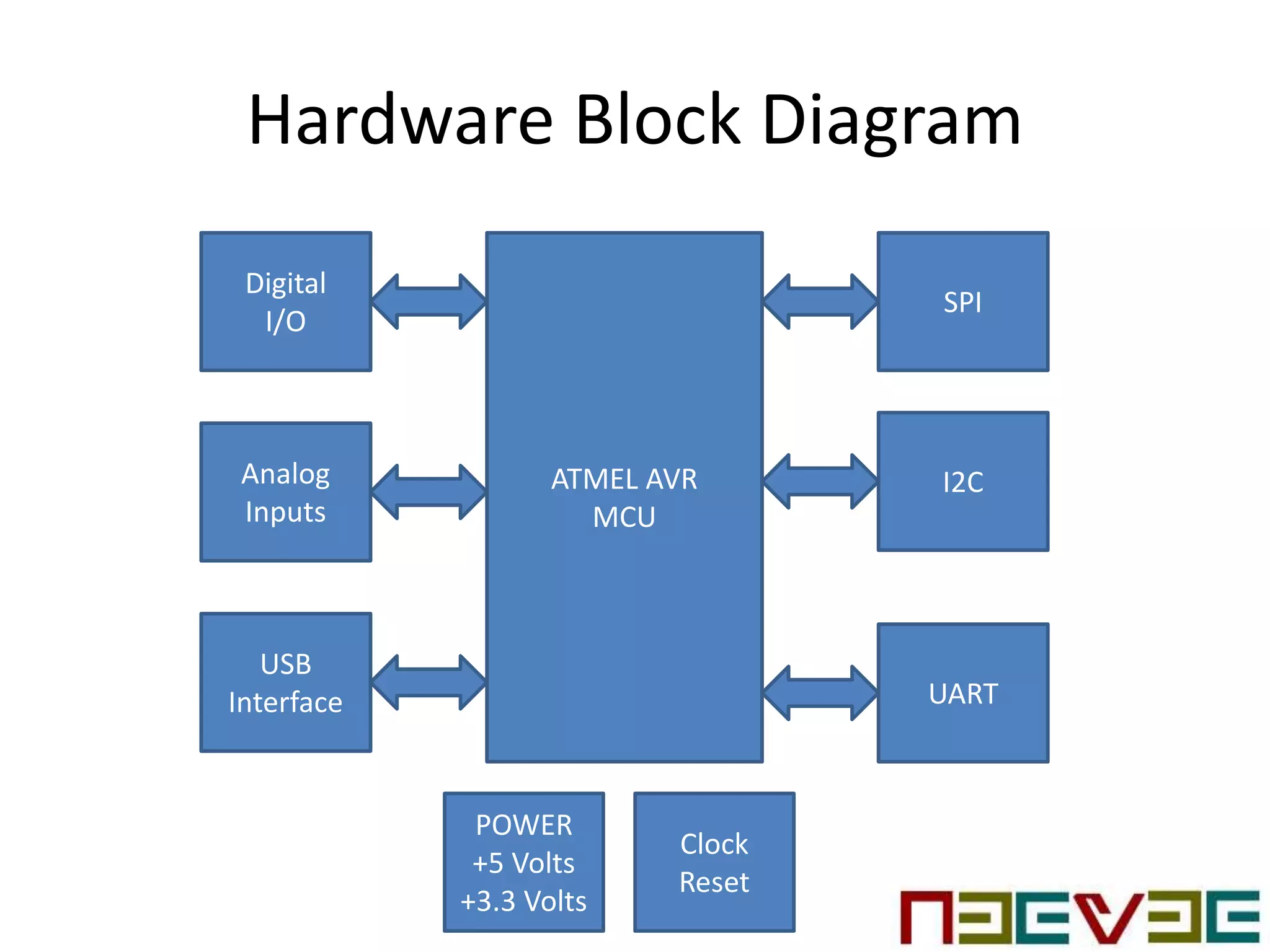
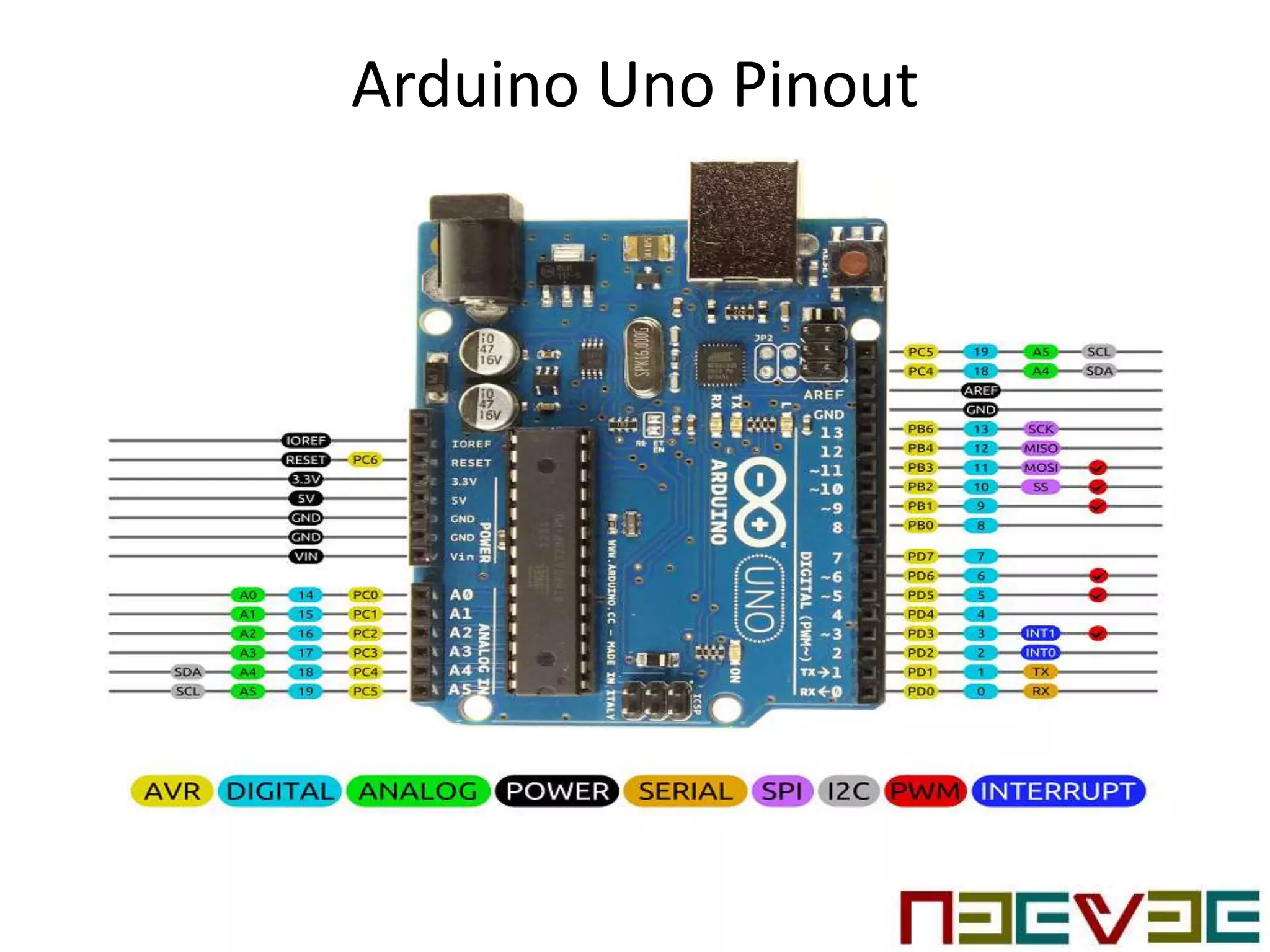
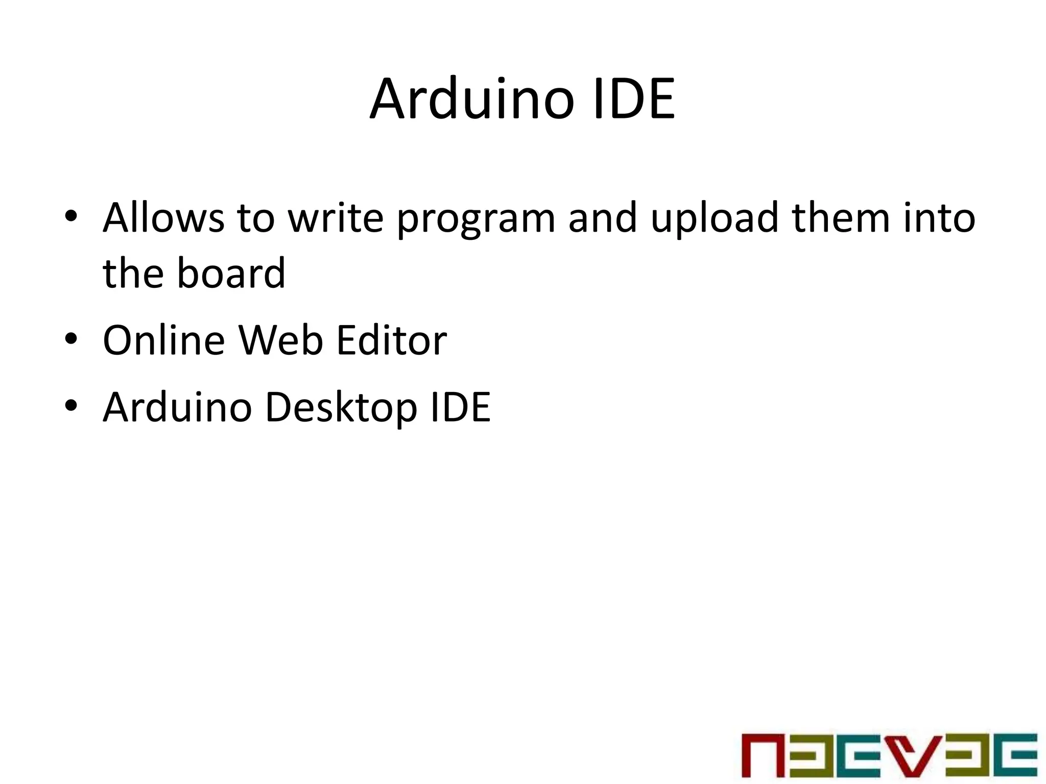
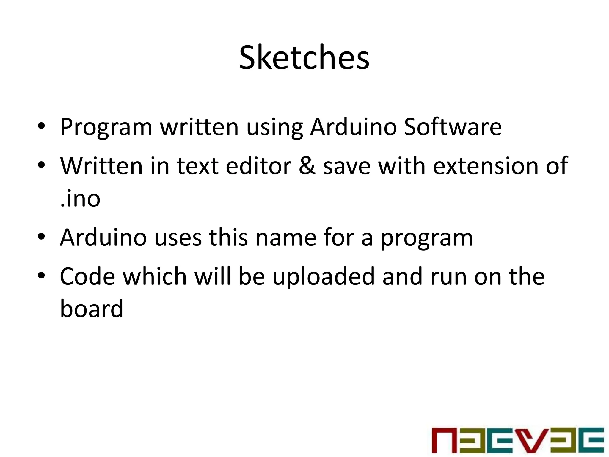
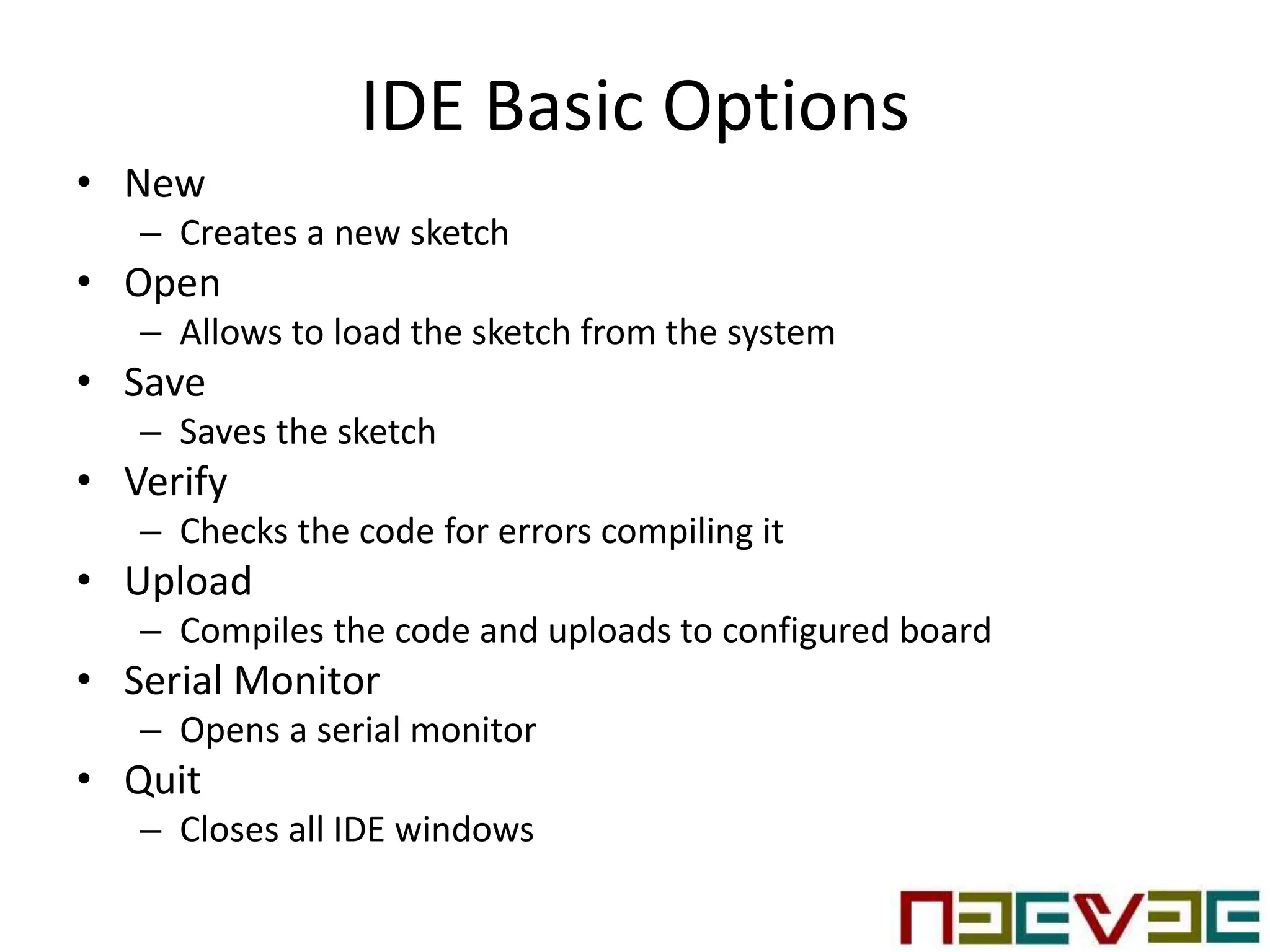
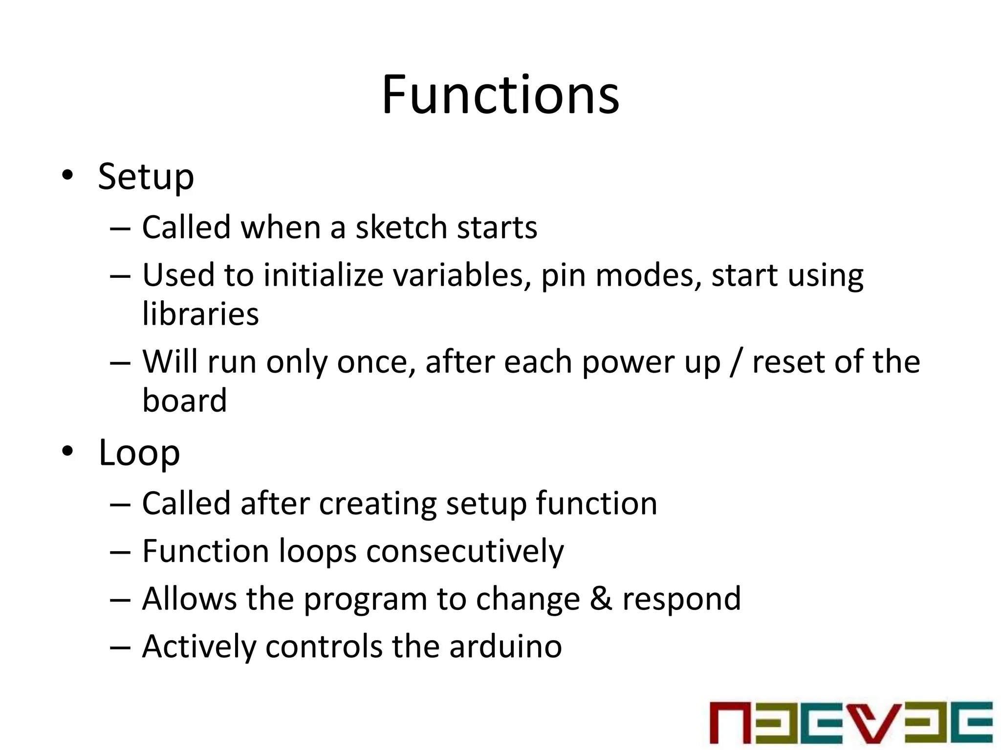
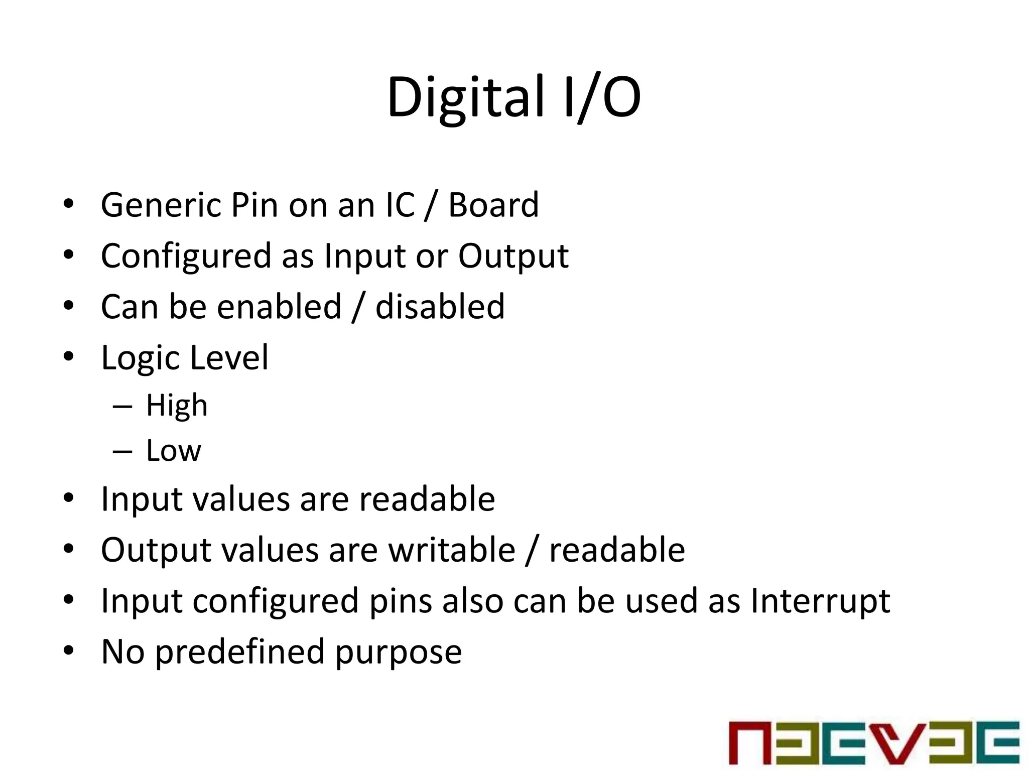
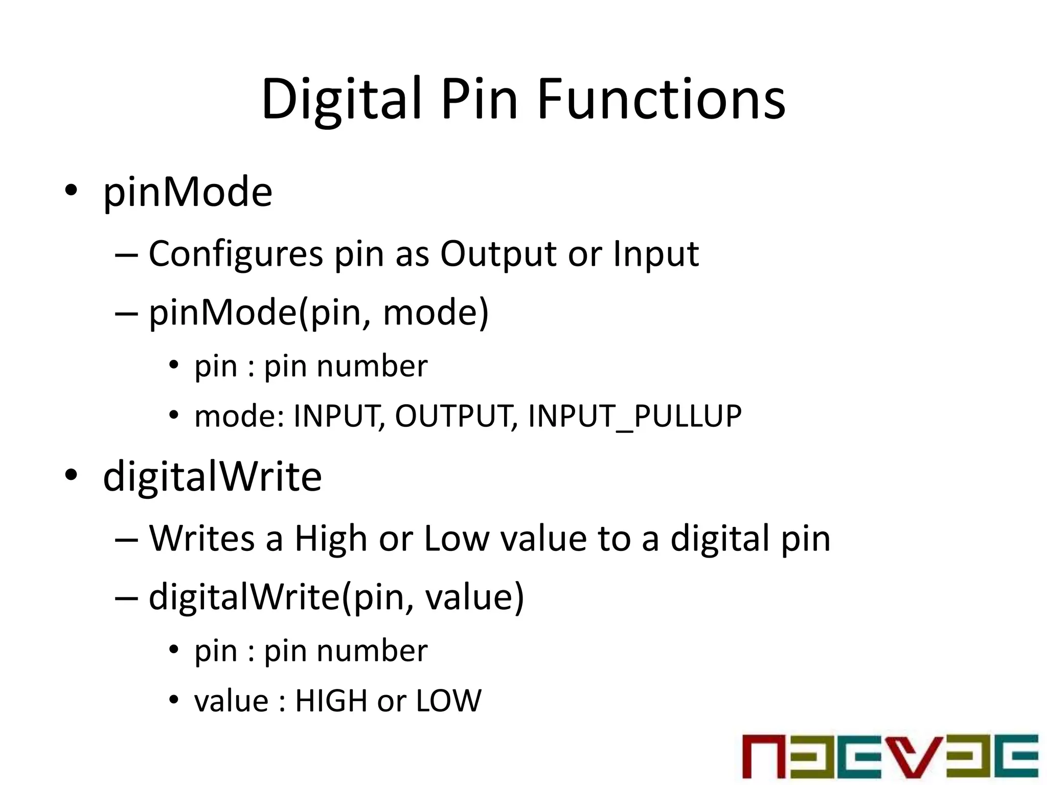
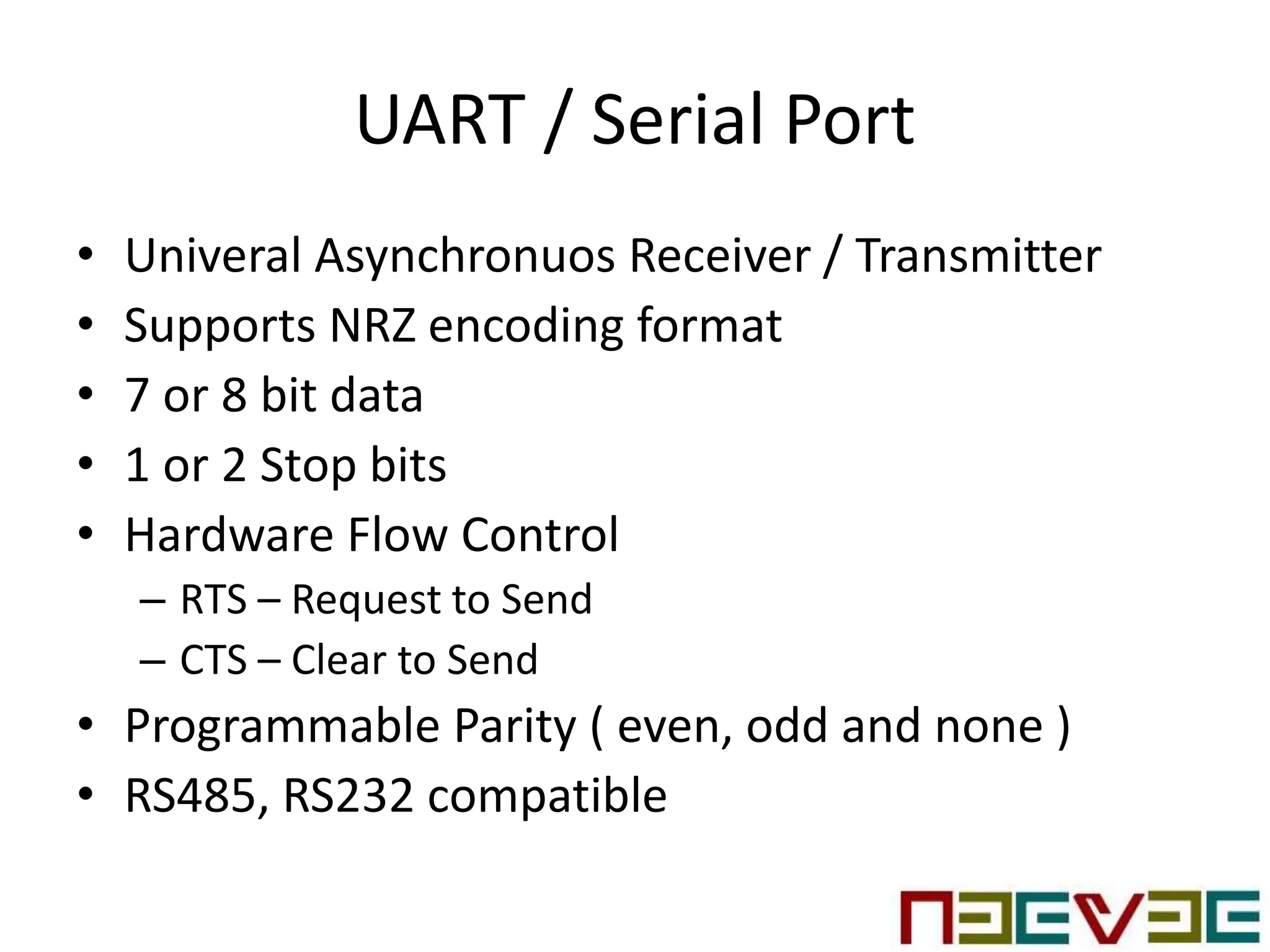
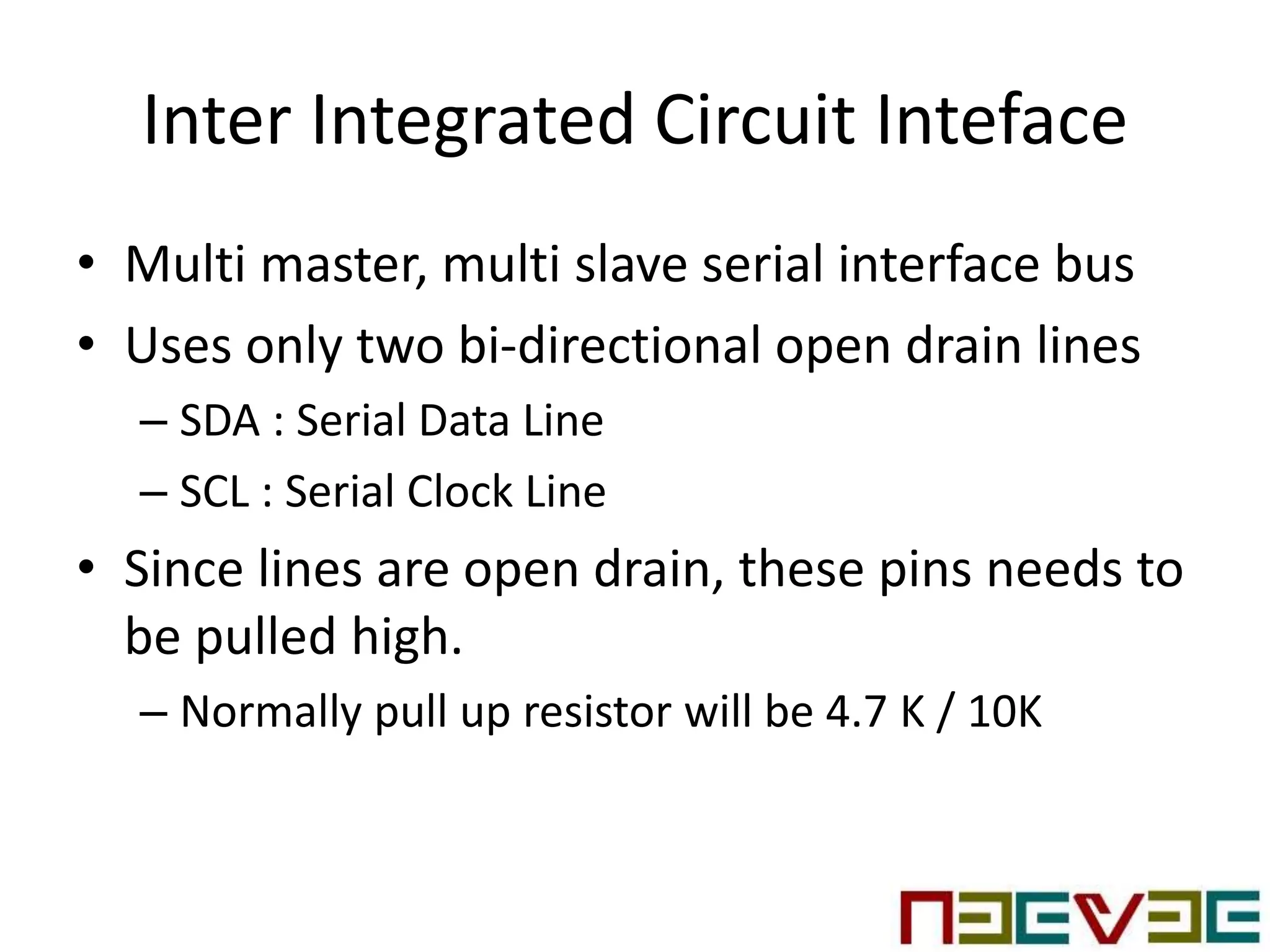
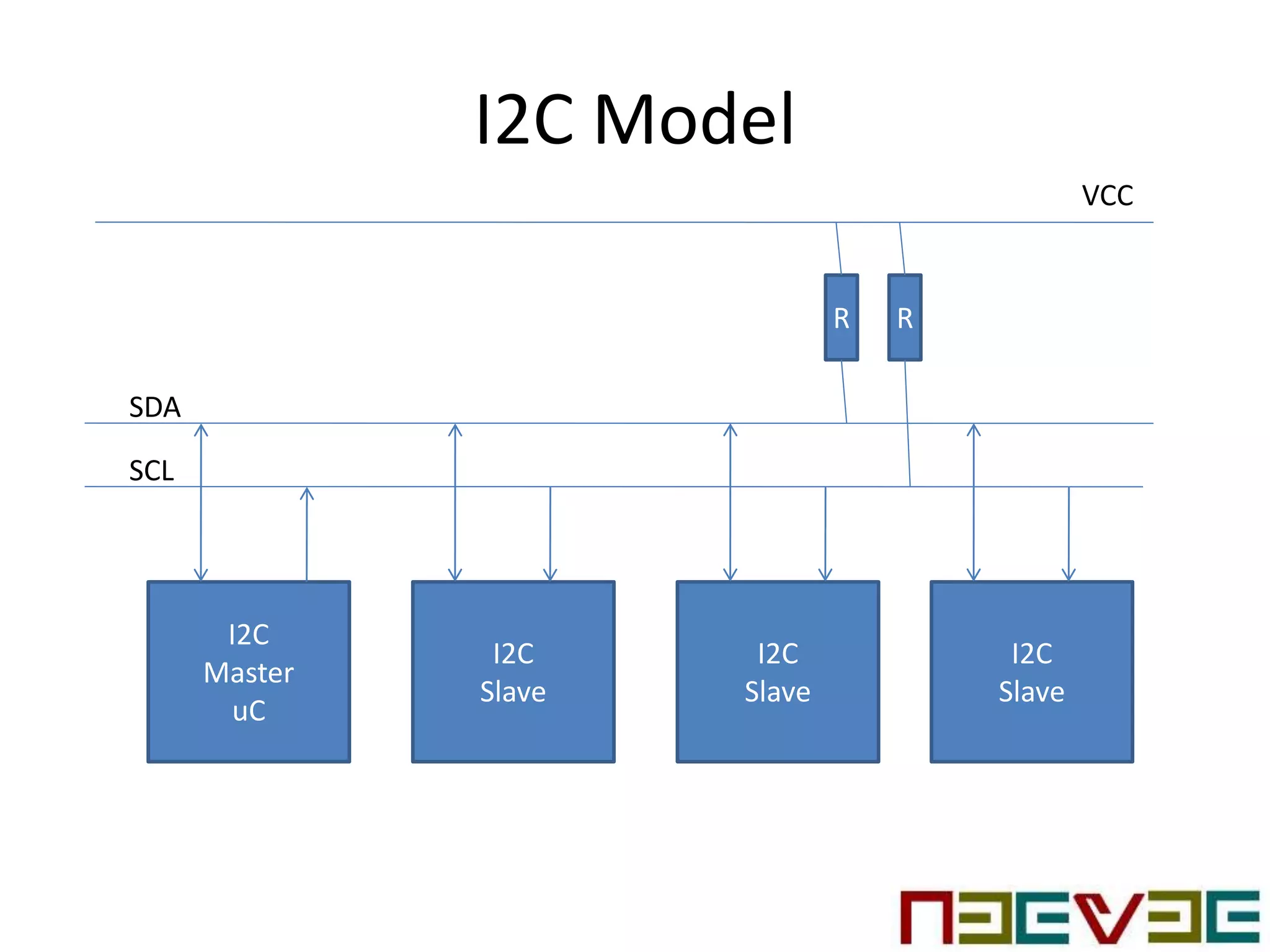
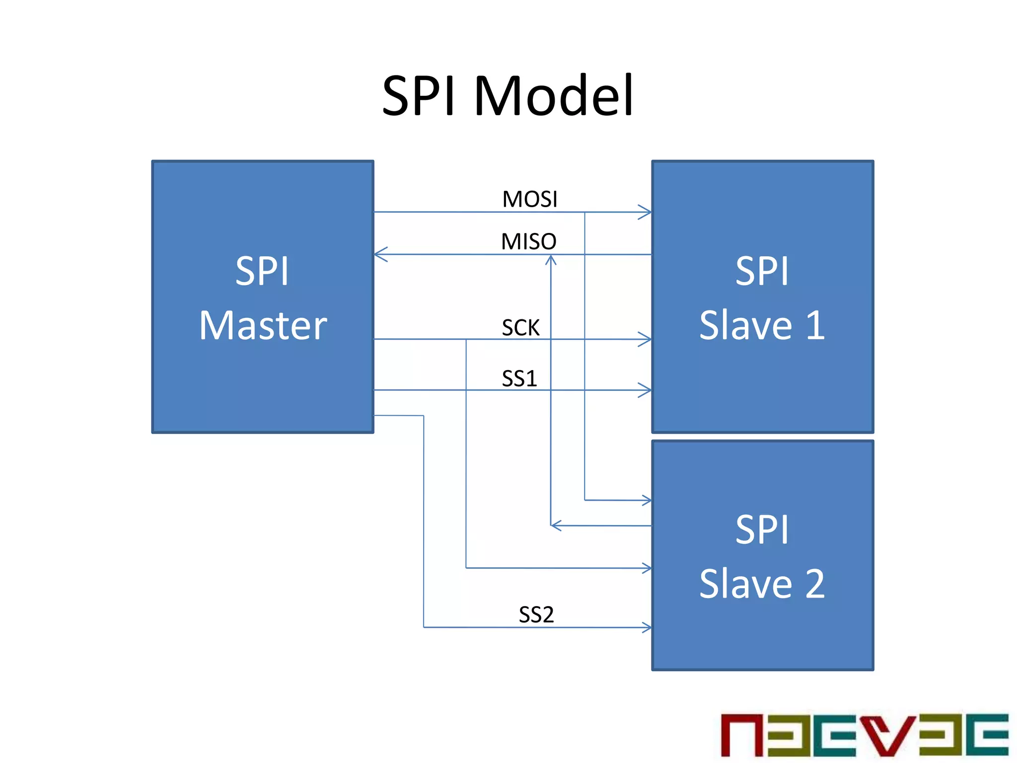
KEMBAR78
Arduino Programming - Brief Introduction | PPTX
Arduino Board
Programming
Overview
What is Arduino
• Open source electronics platform
– Easy to use hardware & software
• Equipped with sets of analog & digital I/Os
• Can be interfaced to extension boards ( shields)
• Features USB based communication interface
• Provided with Integrated Development
Environment
• Aimed to provide low-cost and easy way for
students & professionals
• GNU General Public License
Arduino Board
Hardware Block Diagram
ATMEL AVR
MCU
SPI
I2C
UART
Digital
I/O
Analog
Inputs
USB
Interface
POWER
+5 Volts
+3.3 Volts
Clock
Reset
Arduino Uno Pinout
Arduino IDE
• Allows to write program and upload them into
the board
• Online Web Editor
• Arduino Desktop IDE
Sketches
• Program written using Arduino Software
• Written in text editor & save with extension of
.ino
• Arduino uses this name for a program
• Code which will be uploaded and run on the
board
IDE Basic Options
• New
– Creates a new sketch
• Open
– Allows to load the sketch from the system
• Save
– Saves the sketch
• Verify
– Checks the code for errors compiling it
• Upload
– Compiles the code and uploads to configured board
• Serial Monitor
– Opens a serial monitor
• Quit
– Closes all IDE windows
Variables
• a place to store the data
• Has name, value and type
– Example declaration
– int pin = 2;
• Specified only once and can be used many
times
• Variable assignment
– pin = 3;
Functions
• Setup
– Called when a sketch starts
– Used to initialize variables, pin modes, start using
libraries
– Will run only once, after each power up / reset of the
board
• Loop
– Called after creating setup function
– Function loops consecutively
– Allows the program to change & respond
– Actively controls the arduino
Digital I/O
• Generic Pin on an IC / Board
• Configured as Input or Output
• Can be enabled / disabled
• Logic Level
– High
– Low
• Input values are readable
• Output values are writable / readable
• Input configured pins also can be used as Interrupt
• No predefined purpose
Digital Pin Functions
• pinMode
– Configures pin as Output or Input
– pinMode(pin, mode)
• pin : pin number
• mode: INPUT, OUTPUT, INPUT_PULLUP
• digitalWrite
– Writes a High or Low value to a digital pin
– digitalWrite(pin, value)
• pin : pin number
• value : HIGH or LOW
Digital Pin Functions…
• digitalRead
– Reads the current value of specified pin
– int digitalRead(pin)
• pin : pin number
• Returns the current value
UART / Serial Port
• Univeral Asynchronuos Receiver / Transmitter
• Supports NRZ encoding format
• 7 or 8 bit data
• 1 or 2 Stop bits
• Hardware Flow Control
– RTS – Request to Send
– CTS – Clear to Send
• Programmable Parity ( even, odd and none )
• RS485, RS232 compatible
UART Interface
NXP
IMX6
UART
Serial
Device
TXD
RXD
RTS
CTS
Serial function
• begin
• end
• print
• println
• readBytes
• readString
• write
• setTimeout
• available
• availableForWrite
Inter Integrated Circuit Inteface
• Multi master, multi slave serial interface bus
• Uses only two bi-directional open drain lines
– SDA : Serial Data Line
– SCL : Serial Clock Line
• Since lines are open drain, these pins needs to
be pulled high.
– Normally pull up resistor will be 4.7 K / 10K
I2C Model
I2C
Master
uC
I2C
Slave
I2C
Slave
I2C
Slave
VCC
SCL
SDA
R R
I2C / Wire Functions
• begin
• receive
• send
• onRequest
• RequestFrom
Serial Peripheral Interface
• Synchronous Serial Communication Interface
• Used for Short distance. Basically with in the
board
• Full duplex mode with master slave architecture
• Also called as four-wire bus
• Pins
– MISO : Master Input Slave Output
– MOSI : Master Output Slave Input
– SCK : Serial Clock
– SS : Slave Select
SPI Model
SPI
Master
SPI
Slave 1
MOSI
MISO
SCK
SS1
SPI
Slave 2
SS2
Contact Us
• Address :
– No 16, First Floor, Ganesh 1st cross street
– Madipakkam Koot Road, Chennai
• Web : www.neeveetech.com
• Email :
– info@neeveetech.com
– sales@neeveetech.com
Thank You

Arduino Programming - Brief Introduction

  • 1.
  • 2.
    What is Arduino •Open source electronics platform – Easy to use hardware & software • Equipped with sets of analog & digital I/Os • Can be interfaced to extension boards ( shields) • Features USB based communication interface • Provided with Integrated Development Environment • Aimed to provide low-cost and easy way for students & professionals • GNU General Public License
  • 3.
  • 4.
    Hardware Block Diagram ATMELAVR MCU SPI I2C UART Digital I/O Analog Inputs USB Interface POWER +5 Volts +3.3 Volts Clock Reset
  • 5.
  • 6.
    Arduino IDE • Allowsto write program and upload them into the board • Online Web Editor • Arduino Desktop IDE
  • 7.
    Sketches • Program writtenusing Arduino Software • Written in text editor & save with extension of .ino • Arduino uses this name for a program • Code which will be uploaded and run on the board
  • 8.
    IDE Basic Options •New – Creates a new sketch • Open – Allows to load the sketch from the system • Save – Saves the sketch • Verify – Checks the code for errors compiling it • Upload – Compiles the code and uploads to configured board • Serial Monitor – Opens a serial monitor • Quit – Closes all IDE windows
  • 9.
    Variables • a placeto store the data • Has name, value and type – Example declaration – int pin = 2; • Specified only once and can be used many times • Variable assignment – pin = 3;
  • 10.
    Functions • Setup – Calledwhen a sketch starts – Used to initialize variables, pin modes, start using libraries – Will run only once, after each power up / reset of the board • Loop – Called after creating setup function – Function loops consecutively – Allows the program to change & respond – Actively controls the arduino
  • 11.
    Digital I/O • GenericPin on an IC / Board • Configured as Input or Output • Can be enabled / disabled • Logic Level – High – Low • Input values are readable • Output values are writable / readable • Input configured pins also can be used as Interrupt • No predefined purpose
  • 12.
    Digital Pin Functions •pinMode – Configures pin as Output or Input – pinMode(pin, mode) • pin : pin number • mode: INPUT, OUTPUT, INPUT_PULLUP • digitalWrite – Writes a High or Low value to a digital pin – digitalWrite(pin, value) • pin : pin number • value : HIGH or LOW
  • 13.
    Digital Pin Functions… •digitalRead – Reads the current value of specified pin – int digitalRead(pin) • pin : pin number • Returns the current value
  • 14.
    UART / SerialPort • Univeral Asynchronuos Receiver / Transmitter • Supports NRZ encoding format • 7 or 8 bit data • 1 or 2 Stop bits • Hardware Flow Control – RTS – Request to Send – CTS – Clear to Send • Programmable Parity ( even, odd and none ) • RS485, RS232 compatible
  • 15.
  • 16.
    Serial function • begin •end • print • println • readBytes • readString • write • setTimeout • available • availableForWrite
  • 17.
    Inter Integrated CircuitInteface • Multi master, multi slave serial interface bus • Uses only two bi-directional open drain lines – SDA : Serial Data Line – SCL : Serial Clock Line • Since lines are open drain, these pins needs to be pulled high. – Normally pull up resistor will be 4.7 K / 10K
  • 18.
  • 19.
    I2C / WireFunctions • begin • receive • send • onRequest • RequestFrom
  • 20.
    Serial Peripheral Interface •Synchronous Serial Communication Interface • Used for Short distance. Basically with in the board • Full duplex mode with master slave architecture • Also called as four-wire bus • Pins – MISO : Master Input Slave Output – MOSI : Master Output Slave Input – SCK : Serial Clock – SS : Slave Select
  • 21.
  • 22.
    Contact Us • Address: – No 16, First Floor, Ganesh 1st cross street – Madipakkam Koot Road, Chennai • Web : www.neeveetech.com • Email : – info@neeveetech.com – sales@neeveetech.com
  • 23.