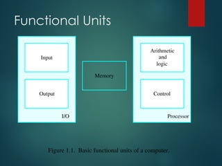
Functional Units
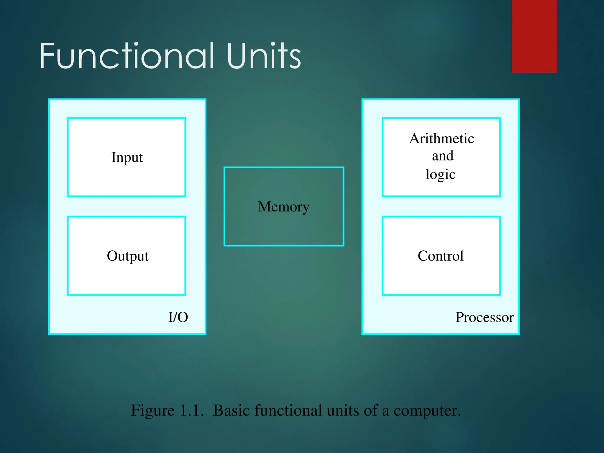
Figure 1.1.Basic functional units of a computer.
I/O Processor
Output
Memory
Input and
Arithmetic
logic
Control
4.
Functional Units
Figure 1.1.Basic functional units of a computer.
I/O Processor
Output
Memory
Input and
Arithmetic
logic
Control
5.
Functional Units
Figure 1.1.Basic functional units of a computer.
I/O Processor
Output
Memory
Input and
Arithmetic
logic
Control
6.
Functional Units
Figure 1.1.Basic functional units of a computer.
I/O Processor
Output
Memory
Input and
Arithmetic
logic
Control
7.
Functional Units
Figure 1.1.Basic functional units of a computer.
I/O Processor
Output
Memory
Input and
Arithmetic
logic
Control
8.
Functional Units
Figure 1.1.Basic functional units of a computer.
I/O Processor
Output
Memory
Input and
Arithmetic
logic
Control
9.
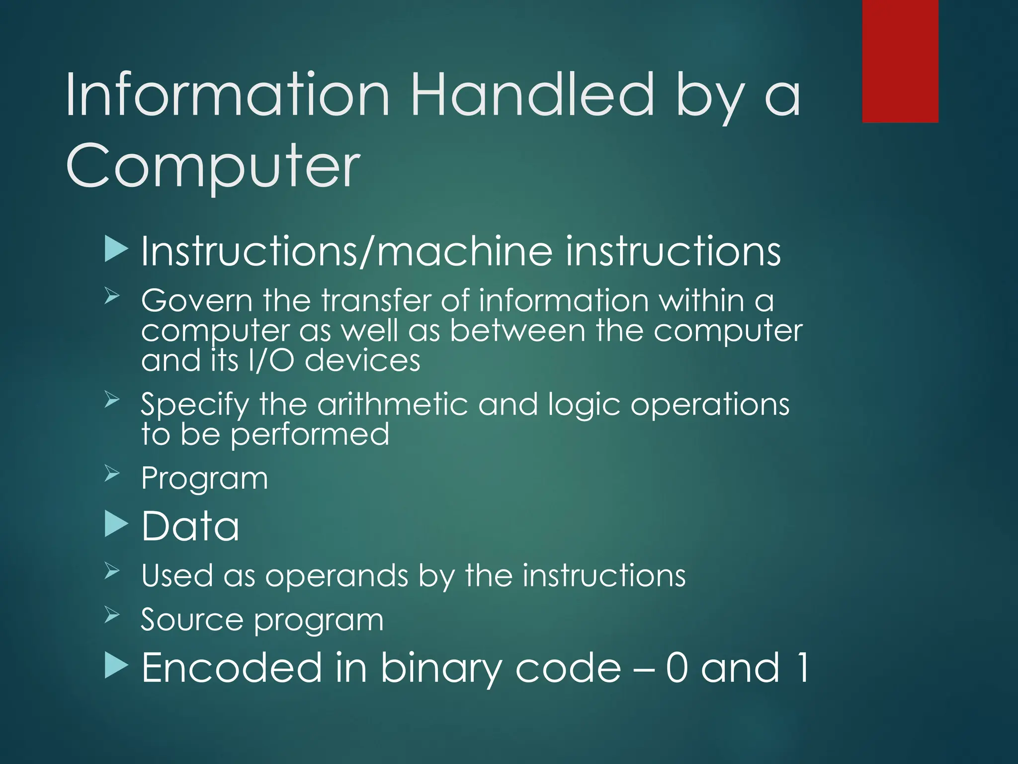
Information Handled bya
Computer
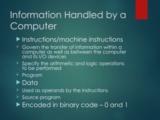
Instructions/machine instructions
Govern the transfer of information within a
computer as well as between the computer
and its I/O devices
Specify the arithmetic and logic operations
to be performed
Program
Data
Used as operands by the instructions
Source program
Encoded in binary code – 0 and 1
10.
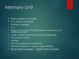
Memory Unit
Storeprograms and data
Two classes of storage
Primary storage
Fast
Programs must be stored in memory while they are
being executed
Large number of semiconductor storage cells
Processed in words
Address
RAM and memory access time
Memory hierarchy – cache, main memory
Secondary storage – larger and cheaper
11.
Arithmetic and LogicUnit
(ALU)
Most computer operations are executed in ALU of
the processor.
Load the operands into memory – bring them to
the processor – perform operation in ALU – store
the result back to memory or retain in the
processor.
Registers
Fast control of ALU
12.
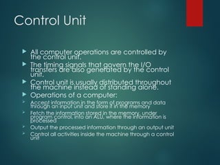
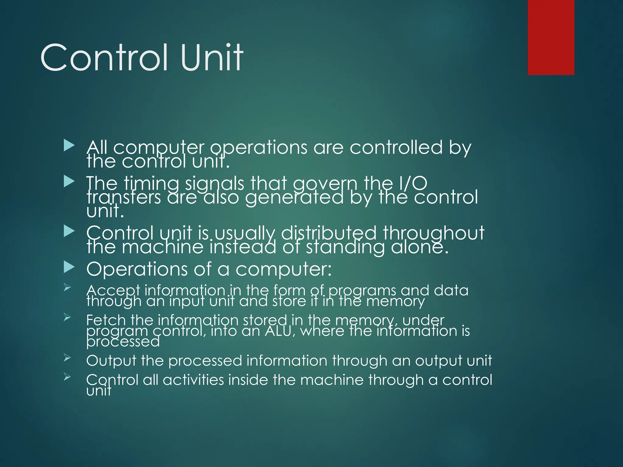
Control Unit
Allcomputer operations are controlled by
the control unit.
The timing signals that govern the I/O
transfers are also generated by the control
unit.
Control unit is usually distributed throughout
the machine instead of standing alone.
Operations of a computer:
Accept information in the form of programs and data
through an input unit and store it in the memory
Fetch the information stored in the memory, under
program control, into an ALU, where the information is
processed
Output the processed information through an output unit
Control all activities inside the machine through a control
unit
13.
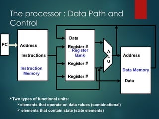
The processor :Data Path and
Control
PC
Register
Bank
Data Memory
Address
Instructions Address
Data
Instruction
Memory
A
L
U
Data
Register #
Register #
Register #
Two types of functional units:
elements that operate on data values (combinational)
elements that contain state (state elements)
14.
Five Execution Steps
Stepname
Step name Action for R-type
Action for R-type
instructions
instructions
Action for Memory-
Action for Memory-
reference Instructions
reference Instructions
Action for
Action for
branches
branches
Action for
Action for
jumps
jumps
Instruction fetch IR = MEM[PC]
PC = PC + 4
Instruction decode/ register
fetch
A = Reg[IR[25-21]]
B = Reg[IR[20-16]]
ALUOut = PC + (sign extend (IR[15-0])<<2)
Execution, address
computation, branch/jump
completion
ALUOut = A op B ALUOut = A+sign
extend(IR[15-0])
IF(A==B) Then
PC=ALUOut
PC=PC[31-
28]||(IR[25-
0]<<2)
Memory access or R-type
completion
Reg[IR[15-11]] =
ALUOut
Load:MDR =Mem[ALUOut]
or
Store:Mem[ALUOut] = B
Memory read completion Load: Reg[IR[20-16]] =
MDR
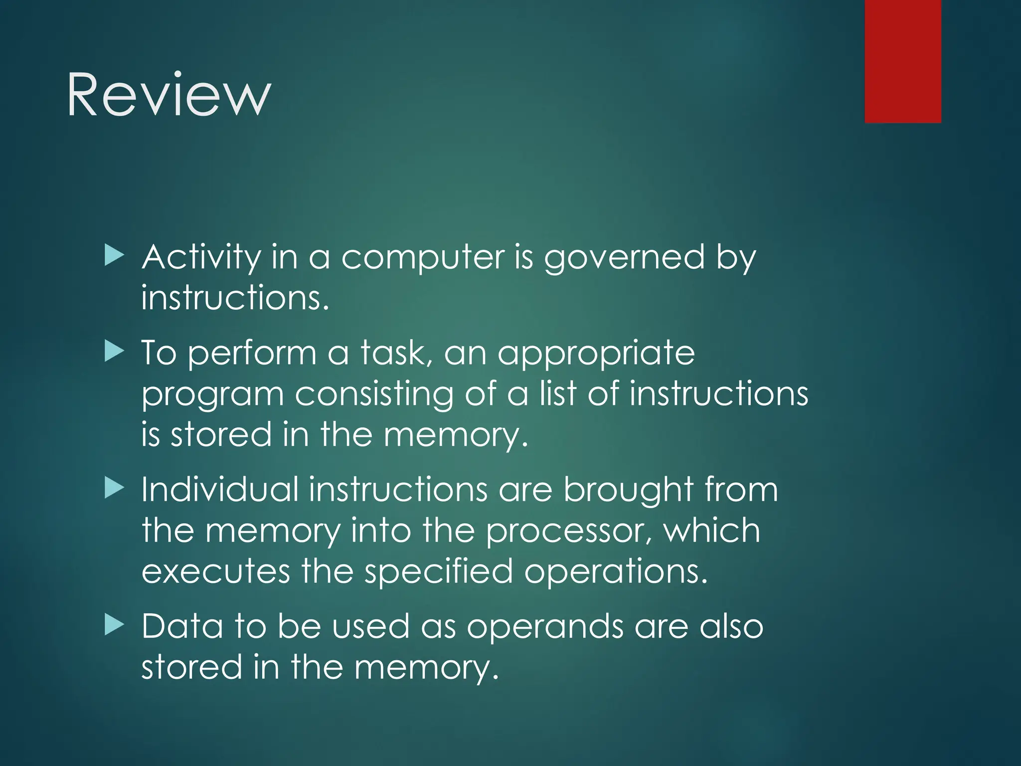
Review
Activity ina computer is governed by
instructions.
To perform a task, an appropriate
program consisting of a list of instructions
is stored in the memory.
Individual instructions are brought from
the memory into the processor, which
executes the specified operations.
Data to be used as operands are also
stored in the memory.
17.
A Typical Instruction
Add LOCA, R0
Add the operand at memory location
LOCA to the operand in a register R0 in
the processor.
Place the sum into register R0.
The original contents of LOCA are
preserved.
The original contents of R0 is overwritten.
Instruction is fetched from the memory
into the processor – the operand at LOCA
is fetched and added to the contents of
R0 – the resulting sum is stored in register
R0.
18.
Separate Memory Access
andALU Operation
Load LOCA, R1
Add R1, R0
Whose contents will be overwritten?
19.
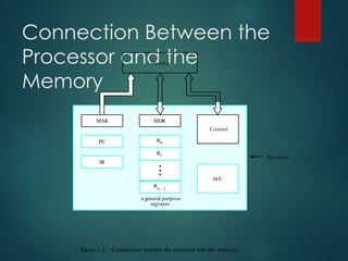
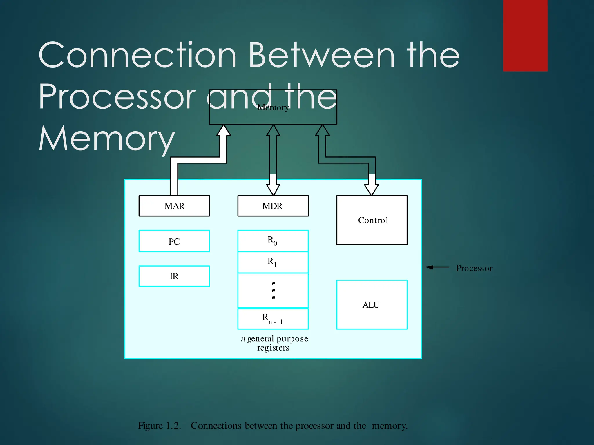
Connection Between the
Processorand the
Memory
Figure 1.2. Connections between the processor and the memory.
Processor
Memory
PC
IR
MDR
Control
ALU
Rn 1
-
R1
R0
MAR
n general purpose
registers
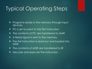
Typical Operating Steps
Programs reside in the memory through input
devices
PC is set to point to the first instruction
The contents of PC are transferred to MAR
A Read signal is sent to the memory
The first instruction is read out and loaded into
MDR
The contents of MDR are transferred to IR
Decode and execute the instruction
22.
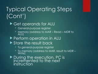
Typical Operating Steps
(Cont’)
Get operands for ALU
General-purpose register
Memory (address to MAR – Read – MDR to
ALU)
Perform operation in ALU
Store the result back
To general-purpose register
To memory (address to MAR, result to MDR –
Write)
During the execution, PC is
incremented to the next
instruction
23.
Interrupt
Normal executionof programs may be
preempted if some device requires
urgent servicing.
The normal execution of the current
program must be interrupted – the
device raises an interrupt signal.
Interrupt-service routine
Current system information backup and
restore (PC, general-purpose registers,
control information, specific information)
24.
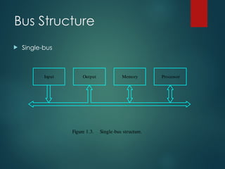
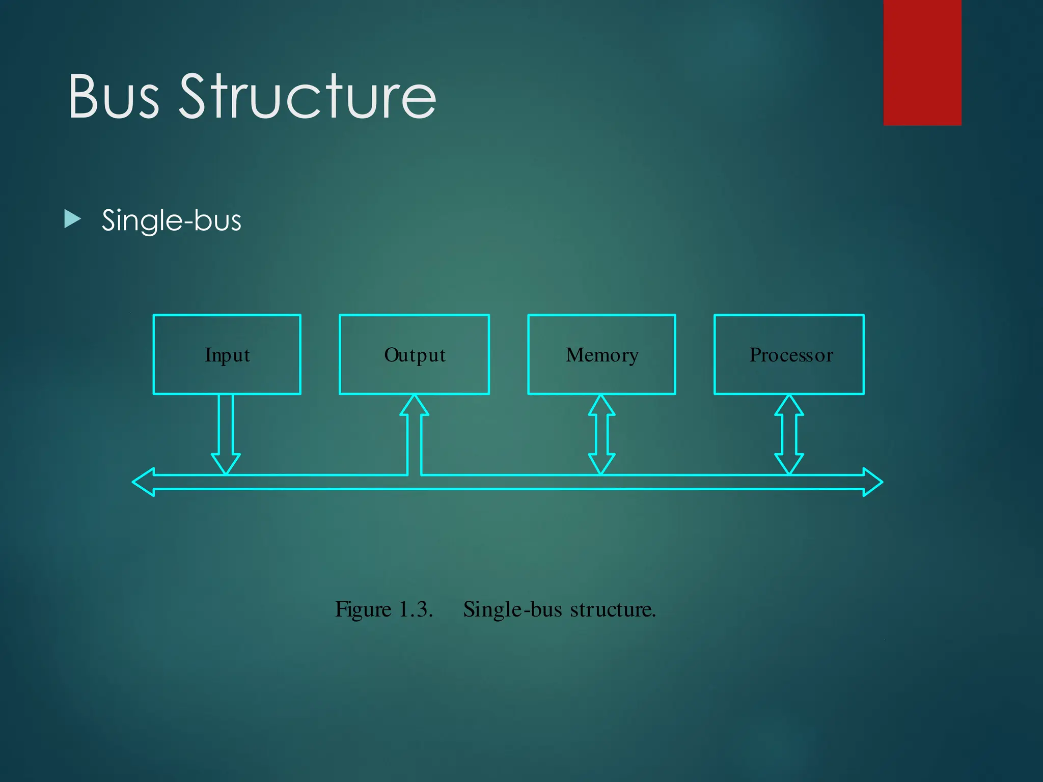
Bus Structures
Thereare many ways to connect different parts
inside a computer together.
A group of lines that serves as a connecting path
for several devices is called a bus.
Address/data/control
Speed Issue
Differentdevices have different transfer/operate
speed.
If the speed of bus is bounded by the slowest
device connected to it, the efficiency will be very
low.
How to solve this?
A common approach – use buffers.
Performance
The mostimportant measure of a computer is
how quickly it can execute programs.
Three factors affect performance:
Hardware design
Instruction set
Compiler
29.
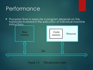
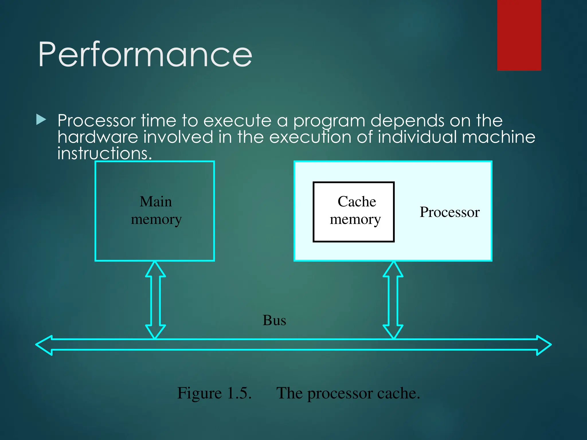
Performance
Processor timeto execute a program depends on the
hardware involved in the execution of individual machine
instructions.
Main
memory Processor
Bus
Cache
memory
Figure 1.5. The processor cache.
30.
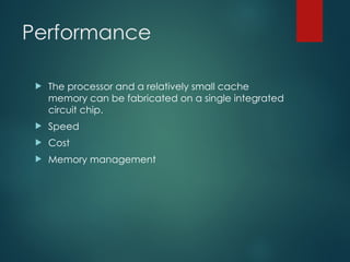
Performance
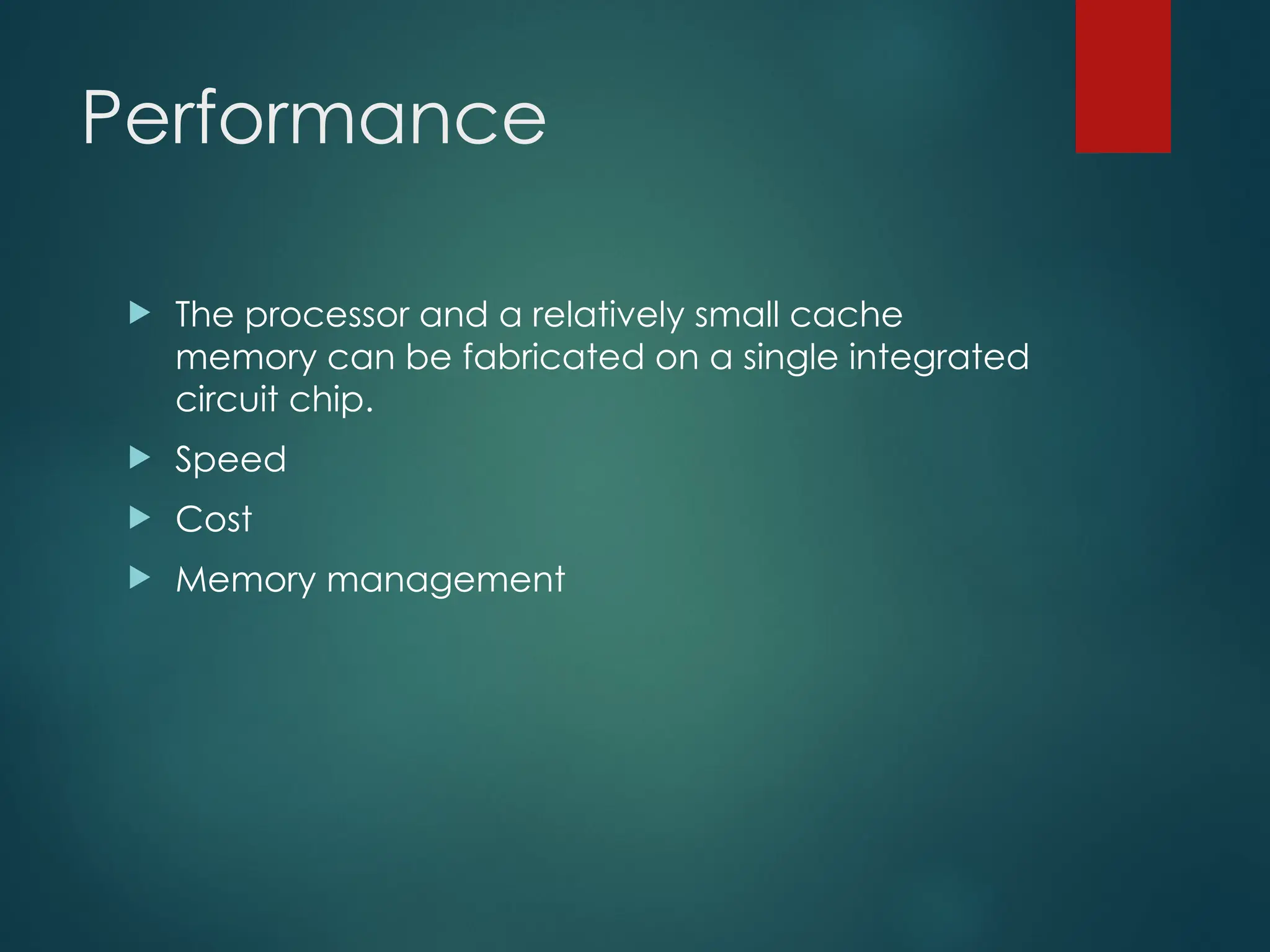
The processorand a relatively small cache
memory can be fabricated on a single integrated
circuit chip.
Speed
Cost
Memory management
31.
Processor Clock
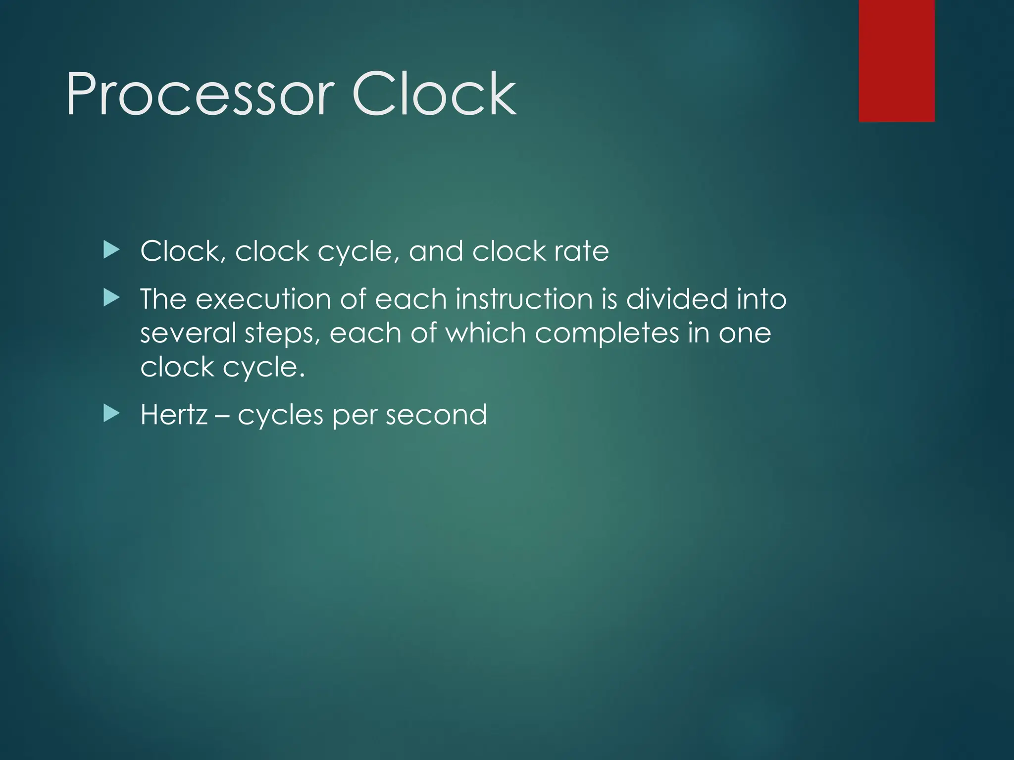
Clock,clock cycle, and clock rate
The execution of each instruction is divided into
several steps, each of which completes in one
clock cycle.
Hertz – cycles per second
32.
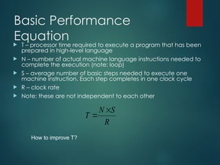
Basic Performance
Equation
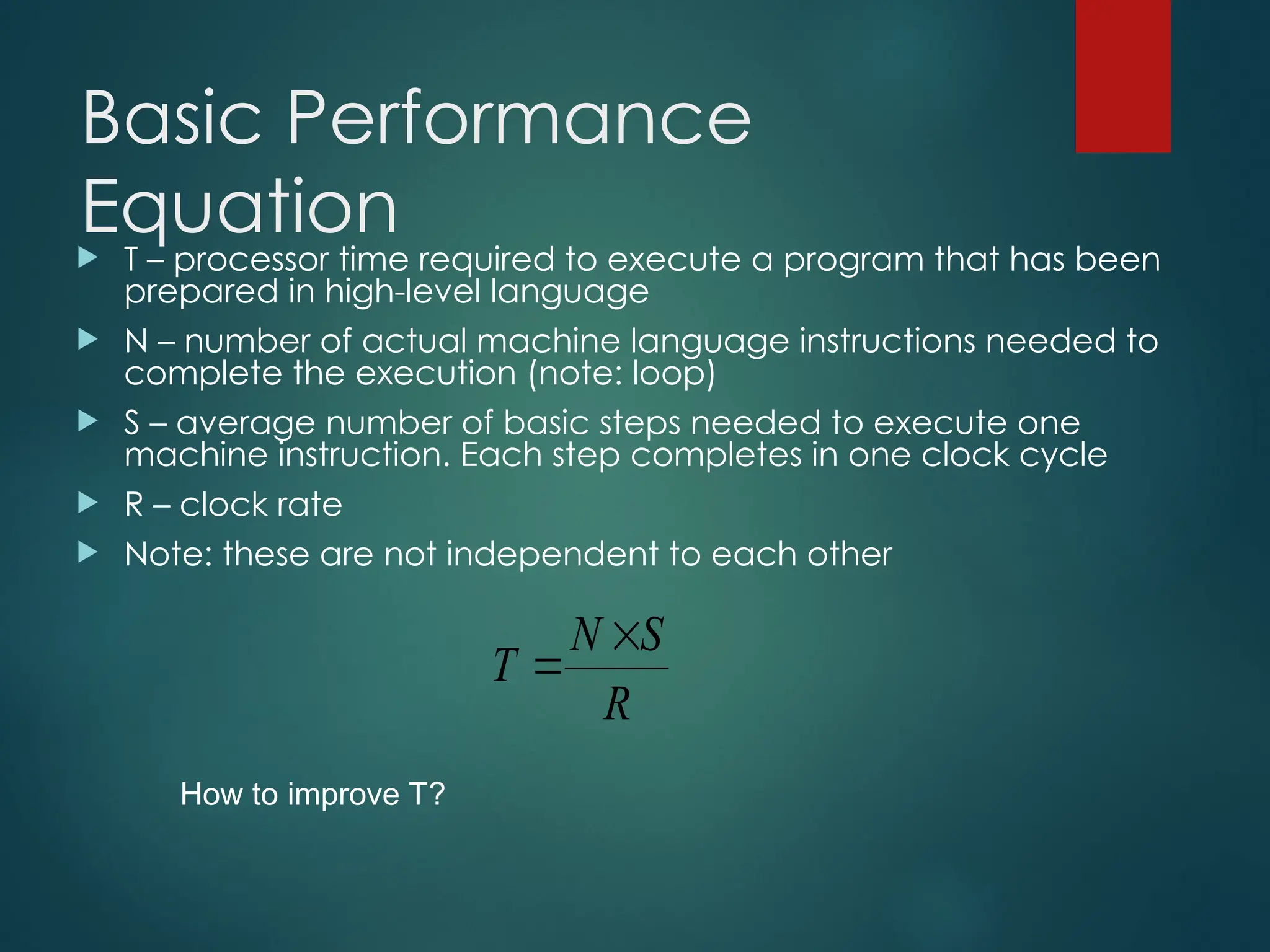
T– processor time required to execute a program that has been
prepared in high-level language
N – number of actual machine language instructions needed to
complete the execution (note: loop)
S – average number of basic steps needed to execute one
machine instruction. Each step completes in one clock cycle
R – clock rate
Note: these are not independent to each other
R
S
N
T
How to improve T?
33.
Pipeline and Superscalar
Operation
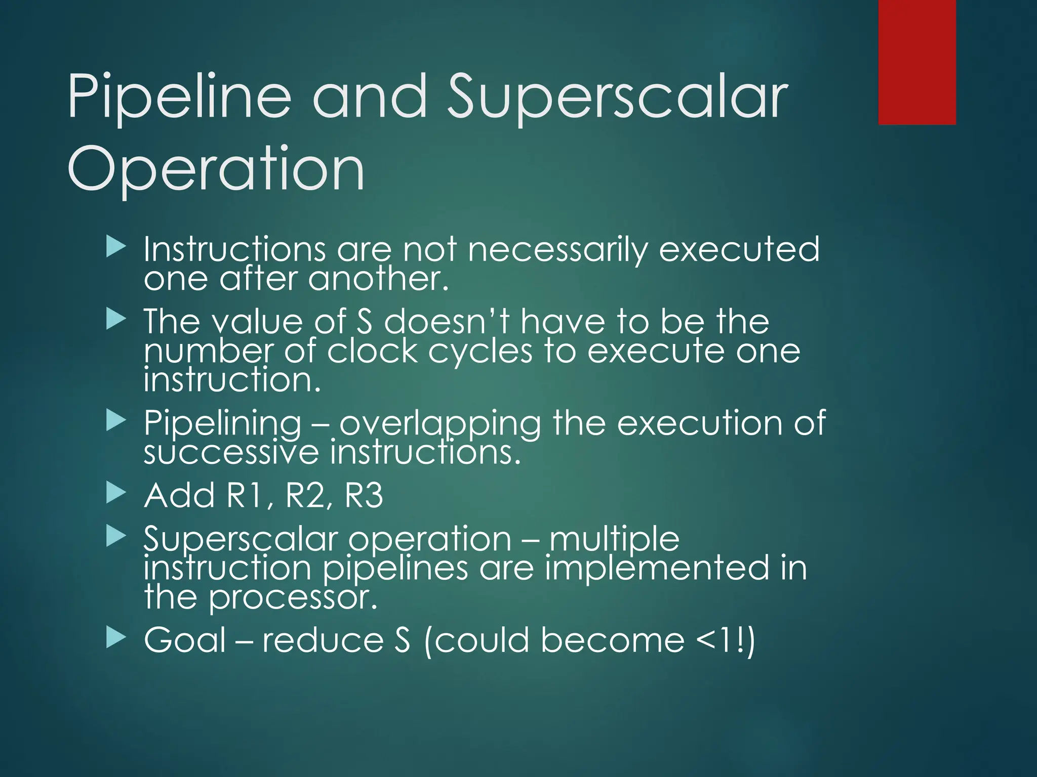
Instructions are not necessarily executed
one after another.
The value of S doesn’t have to be the
number of clock cycles to execute one
instruction.
Pipelining – overlapping the execution of
successive instructions.
Add R1, R2, R3
Superscalar operation – multiple
instruction pipelines are implemented in
the processor.
Goal – reduce S (could become <1!)
34.
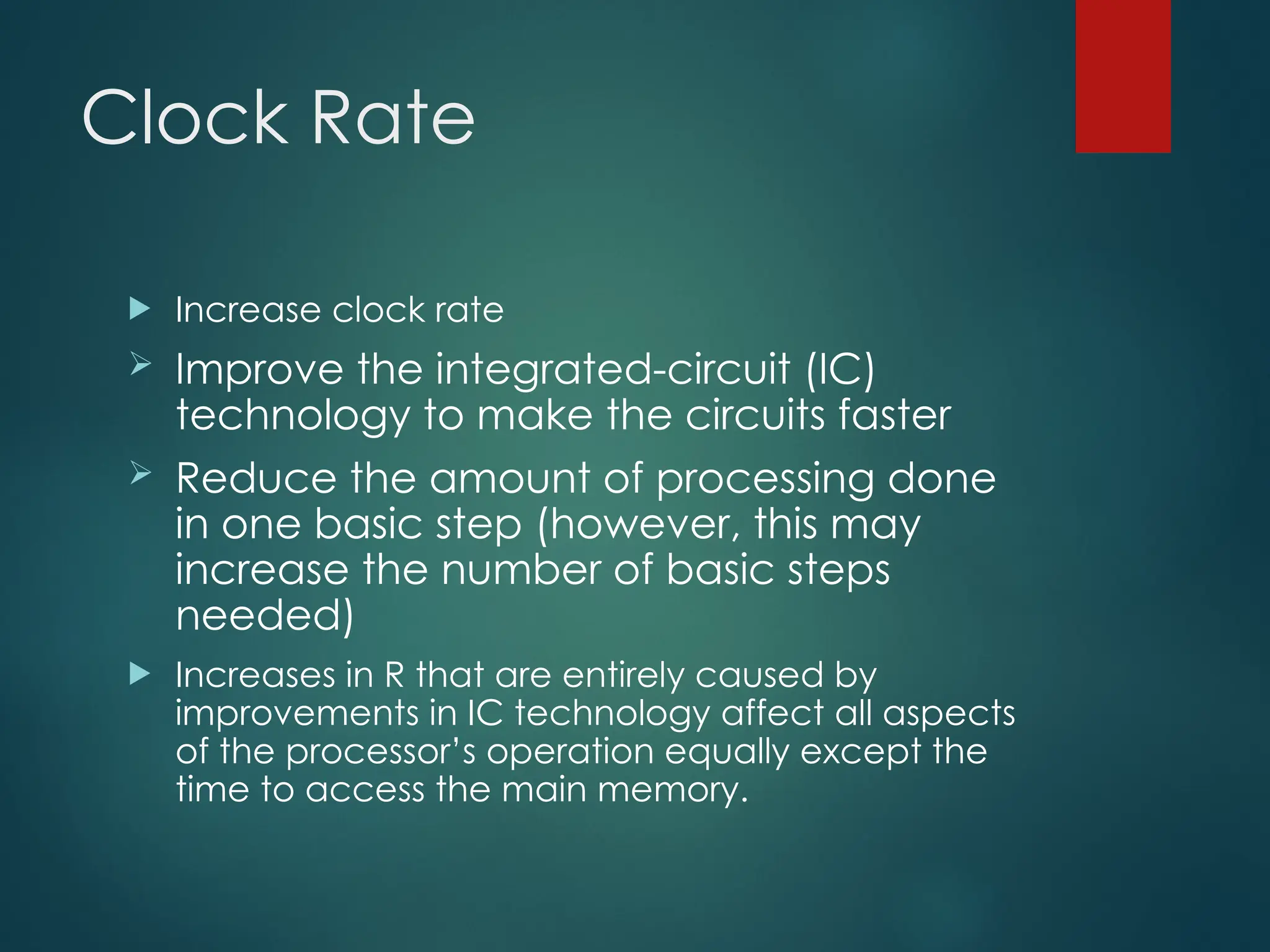
Clock Rate
Increaseclock rate
Improve the integrated-circuit (IC)
technology to make the circuits faster
Reduce the amount of processing done
in one basic step (however, this may
increase the number of basic steps
needed)
Increases in R that are entirely caused by
improvements in IC technology affect all aspects
of the processor’s operation equally except the
time to access the main memory.
35.
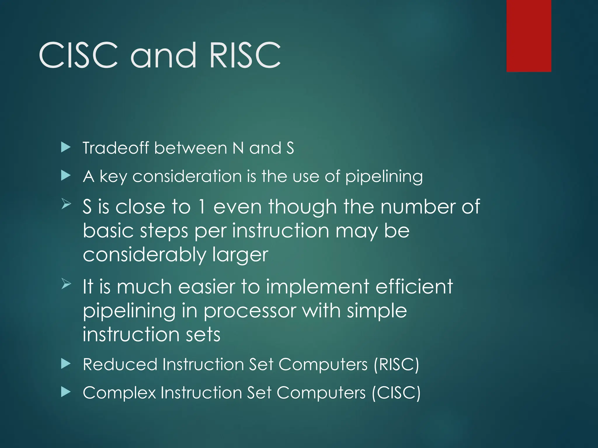
CISC and RISC
Tradeoff between N and S
A key consideration is the use of pipelining
S is close to 1 even though the number of
basic steps per instruction may be
considerably larger
It is much easier to implement efficient
pipelining in processor with simple
instruction sets
Reduced Instruction Set Computers (RISC)
Complex Instruction Set Computers (CISC)
36.
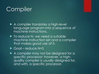
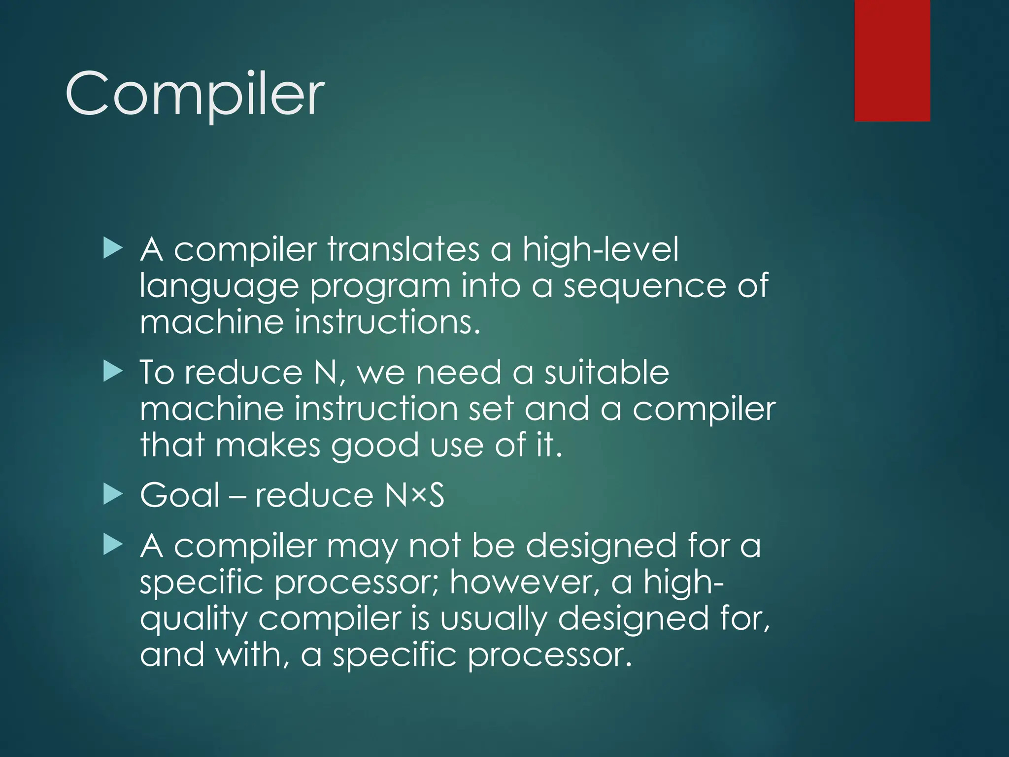
Compiler
A compilertranslates a high-level
language program into a sequence of
machine instructions.
To reduce N, we need a suitable
machine instruction set and a compiler
that makes good use of it.
Goal – reduce N×S
A compiler may not be designed for a
specific processor; however, a high-
quality compiler is usually designed for,
and with, a specific processor.
37.
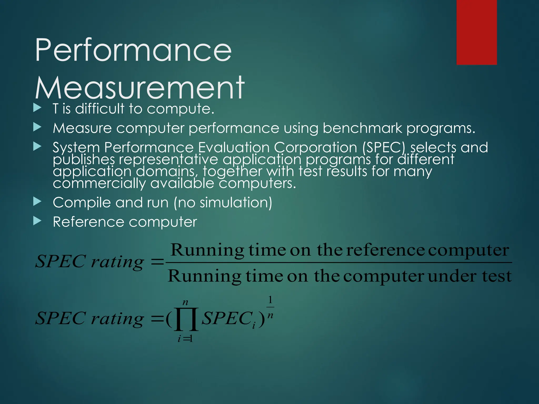
Performance
Measurement
T isdifficult to compute.
Measure computer performance using benchmark programs.
System Performance Evaluation Corporation (SPEC) selects and
publishes representative application programs for different
application domains, together with test results for many
commercially available computers.
Compile and run (no simulation)
Reference computer
n
i
n
i
SPEC
rating
SPEC
rating
SPEC
1
1
)
(
under test
computer
on the
time
Running
computer
reference
on the
time
Running
38.
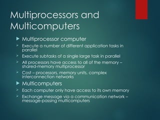
Multiprocessors and
Multicomputers
Multiprocessorcomputer
Execute a number of different application tasks in
parallel
Execute subtasks of a single large task in parallel
All processors have access to all of the memory –
shared-memory multiprocessor
Cost – processors, memory units, complex
interconnection networks
Multicomputers
Each computer only have access to its own memory
Exchange message via a communication network –
message-passing multicomputers
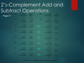
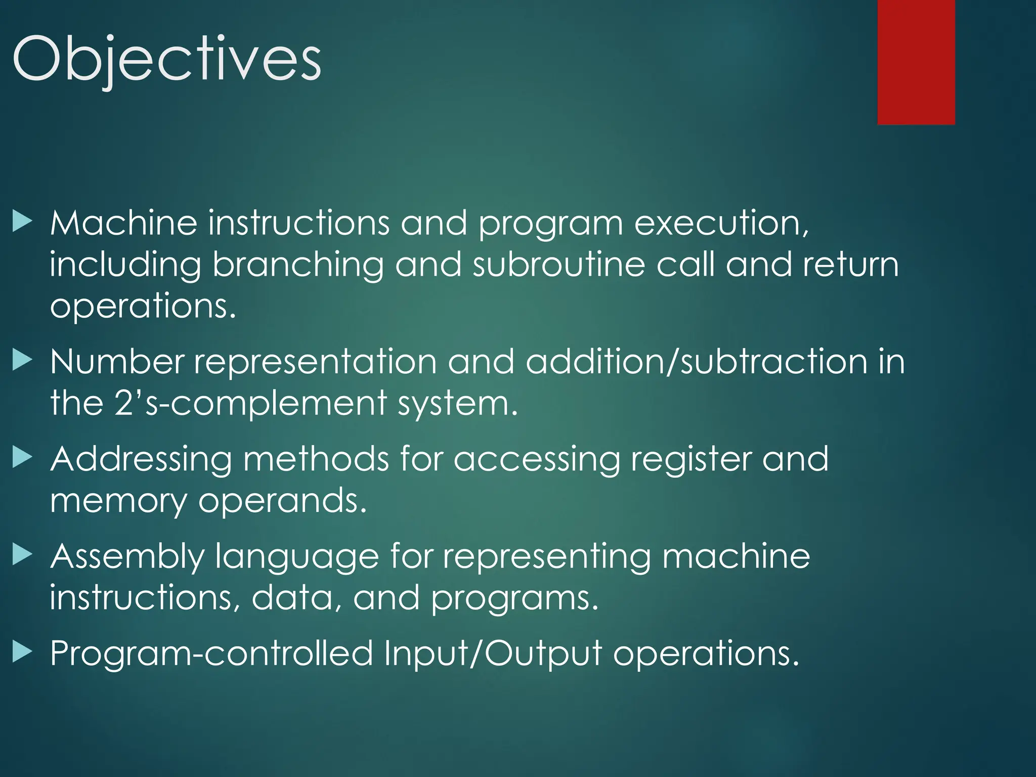
Objectives
Machine instructionsand program execution,
including branching and subroutine call and return
operations.
Number representation and addition/subtraction in
the 2’s-complement system.
Addressing methods for accessing register and
memory operands.
Assembly language for representing machine
instructions, data, and programs.
Program-controlled Input/Output operations.
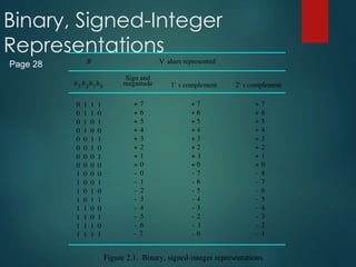
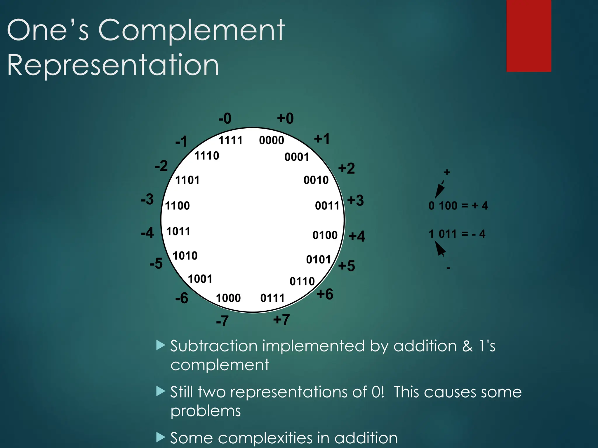
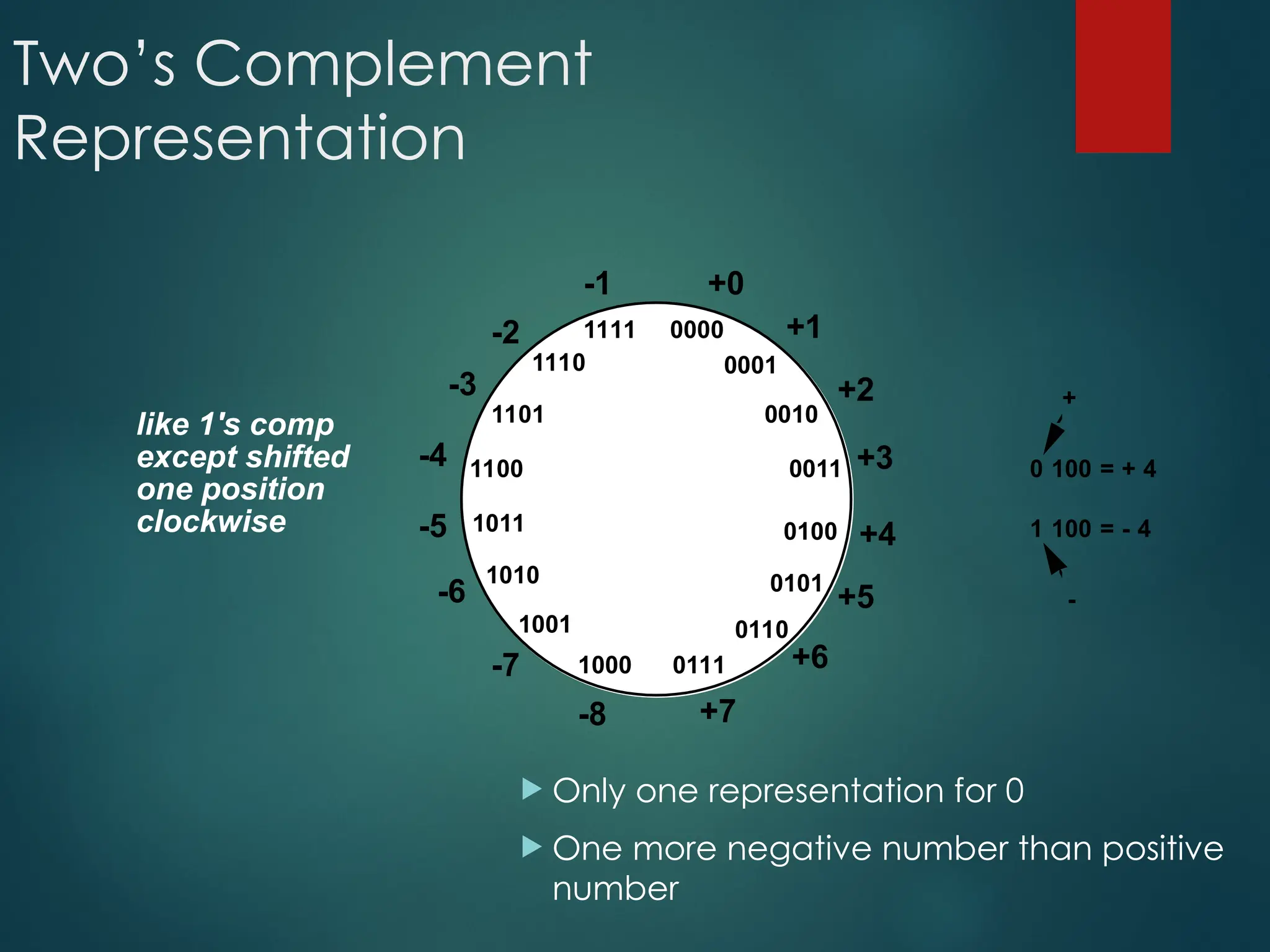
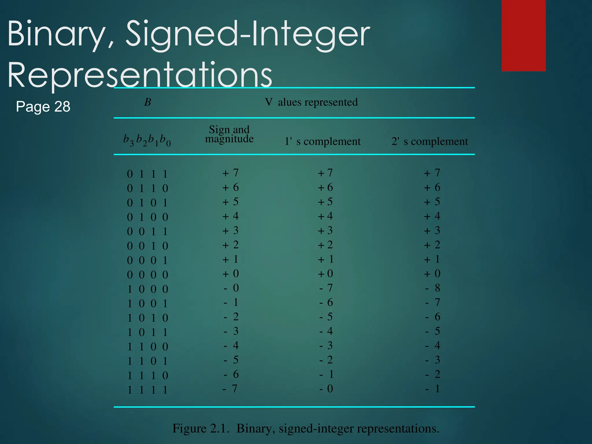
Signed Integer
3major representations:
Sign and magnitude
One’s complement
Two’s complement
Assumptions:
4-bit machine word
16 different values can be represented
Roughly half are positive, half are negative
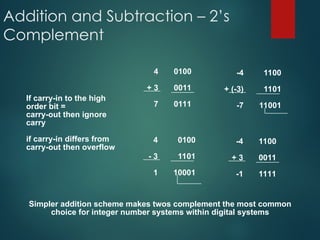
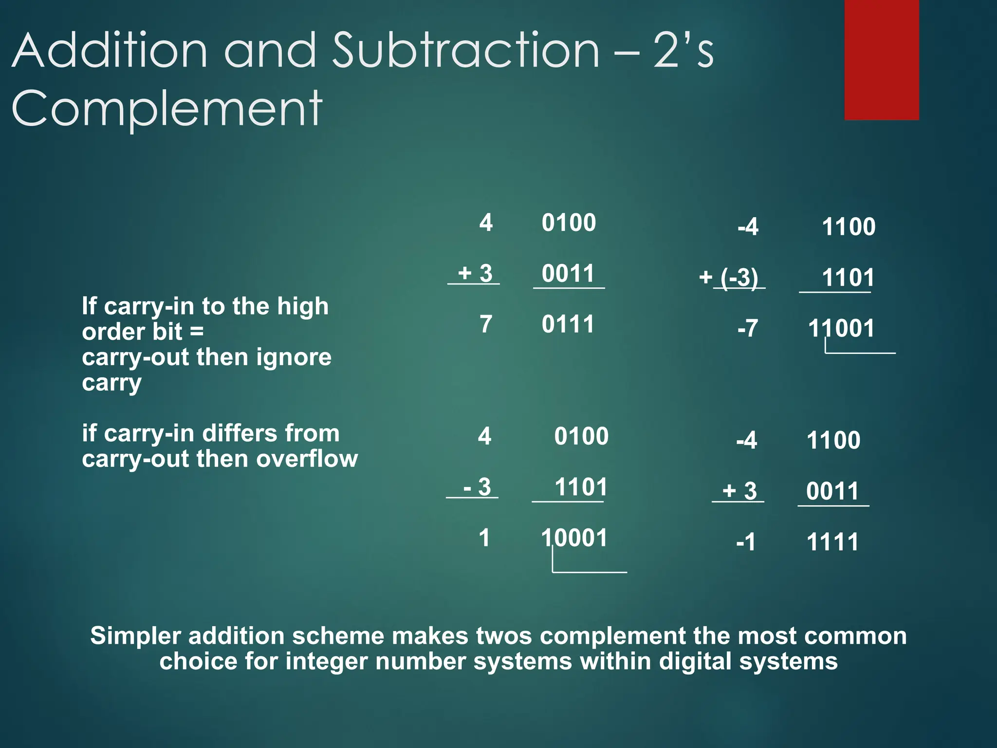
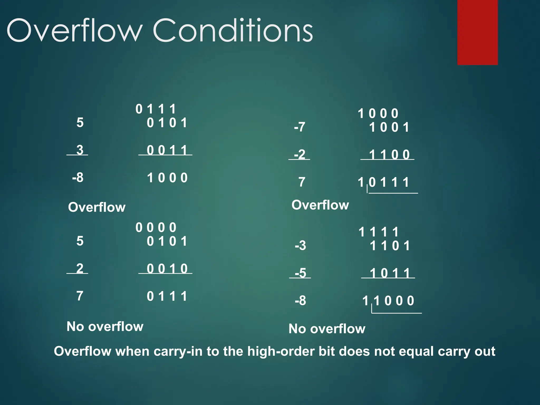
Addition and Subtraction– 2’s
Complement
4
+ 3
7
0100
0011
0111
-4
+ (-3)
-7
1100
1101
11001
4
- 3
1
0100
1101
10001
-4
+ 3
-1
1100
0011
1111
If carry-in to the high
order bit =
carry-out then ignore
carry
if carry-in differs from
carry-out then overflow
Simpler addition scheme makes twos complement the most common
choice for integer number systems within digital systems
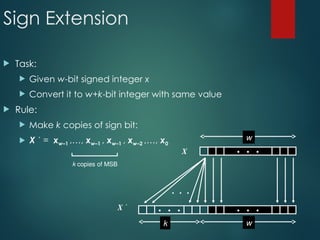
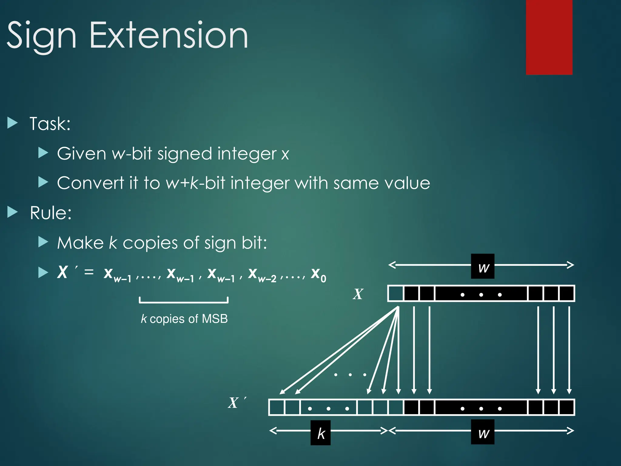
Sign Extension
Task:
Given w-bit signed integer x
Convert it to w+k-bit integer with same value
Rule:
Make k copies of sign bit:
X = xw–1 ,…, xw–1 , xw–1 , xw–2 ,…, x0
k copies of MSB
• • •
X
X • • • • • •
• • •
w
w
k
53.
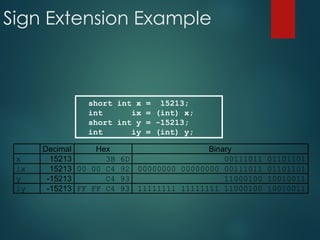
Sign Extension Example
shortint x = 15213;
int ix = (int) x;
short int y = -15213;
int iy = (int) y;
Decimal Hex Binary
x 15213 3B 6D 00111011 01101101
ix 15213 00 00 C4 92 00000000 00000000 00111011 01101101
y -15213 C4 93 11000100 10010011
iy -15213 FF FF C4 93 11111111 11111111 11000100 10010011
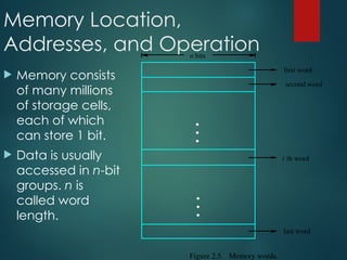
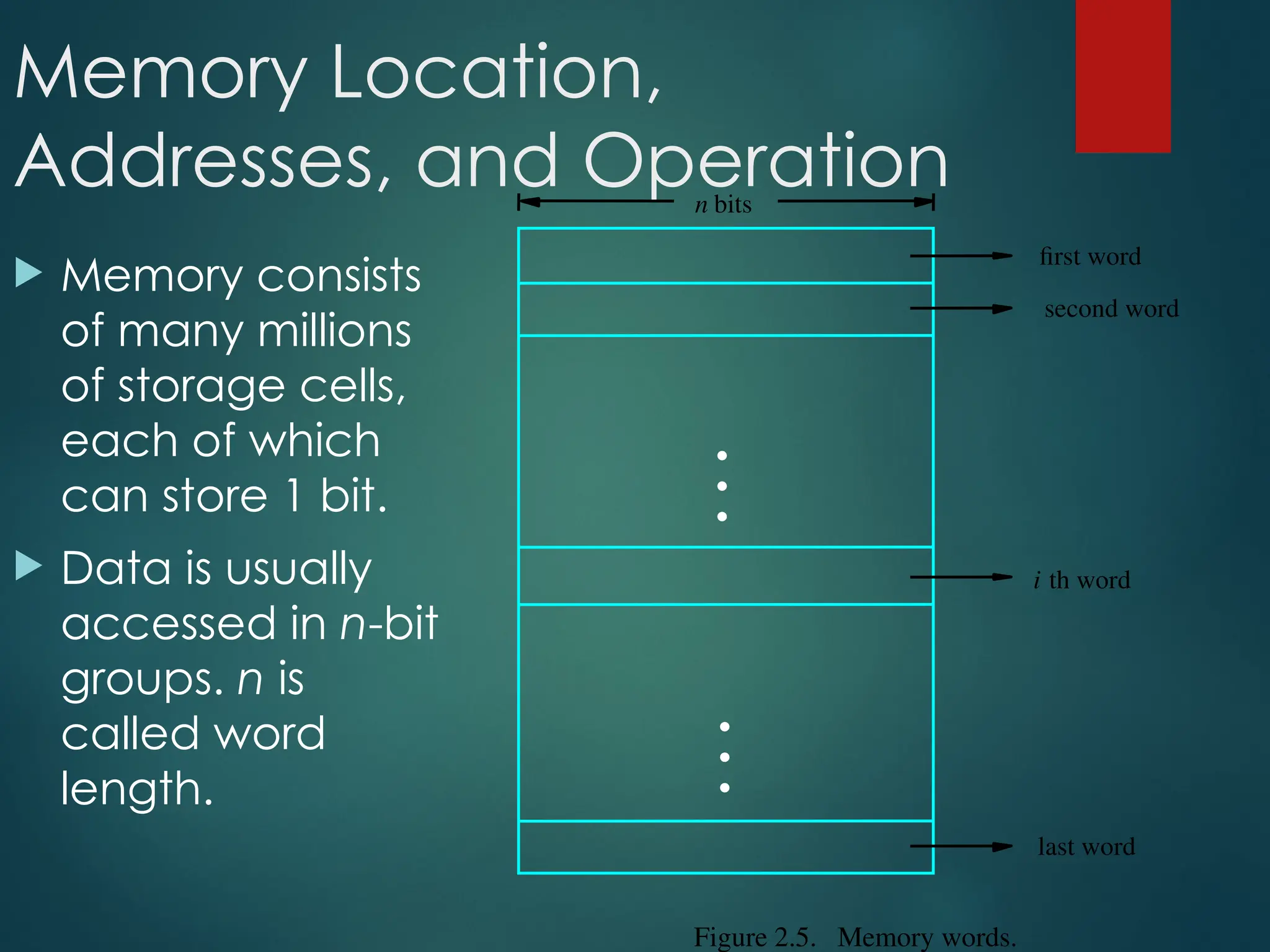
Memory Location,
Addresses, andOperation
Memory consists
of many millions
of storage cells,
each of which
can store 1 bit.
Data is usually
accessed in n-bit
groups. n is
called word
length.
second word
first word
Figure 2.5. Memory words.
n bits
last word
i th word
•
•
•
•
•
•
56.
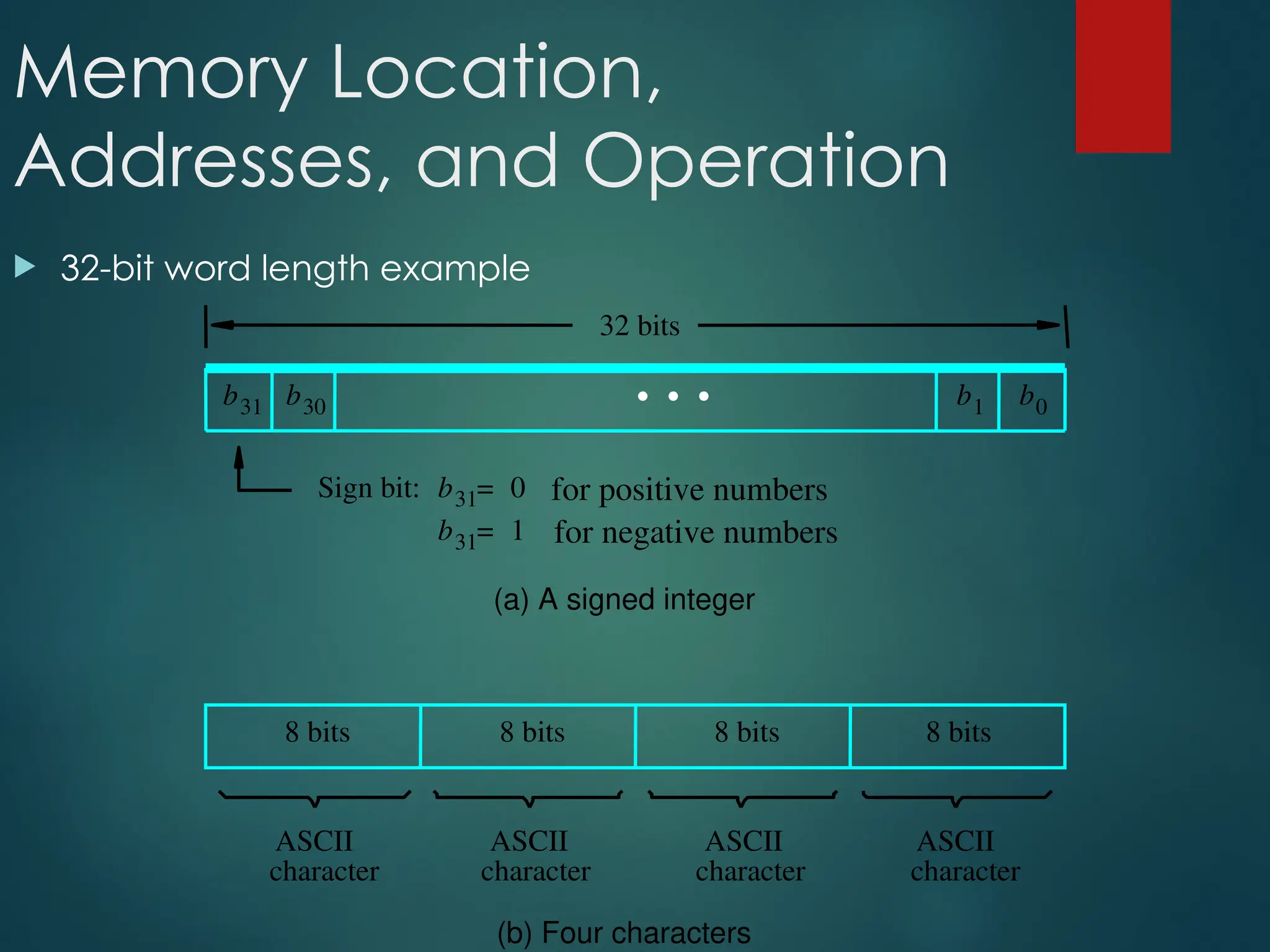
Memory Location,
Addresses, andOperation
32-bit word length example
(b) Four characters
character
character
character character
(a) A signed integer
Sign bit: for positive numbers
for negative numbers
ASCII
ASCII
ASCII
ASCII
32 bits
8 bits 8 bits 8 bits 8 bits
b31 b30 b1 b0
b31 0
=
b31 1
=
•
•
•
57.
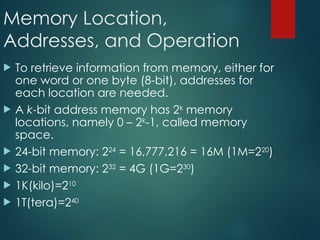
Memory Location,
Addresses, andOperation
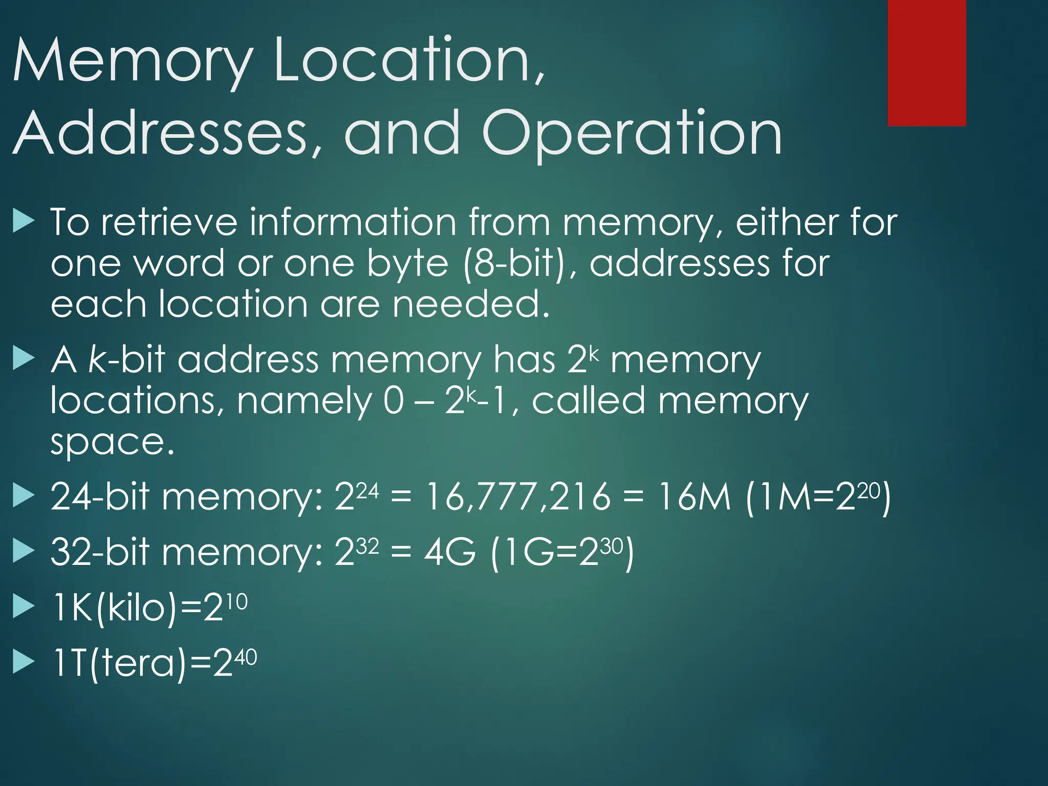
To retrieve information from memory, either for
one word or one byte (8-bit), addresses for
each location are needed.
A k-bit address memory has 2k
memory
locations, namely 0 – 2k
-1, called memory
space.
24-bit memory: 224
= 16,777,216 = 16M (1M=220
)
32-bit memory: 232
= 4G (1G=230
)
1K(kilo)=210
1T(tera)=240
58.
Memory Location,
Addresses, andOperation
It is impractical to assign distinct addresses to individual bit
locations in the memory.
The most practical assignment is to have successive addresses
refer to successive byte locations in the memory – byte-
addressable memory.
Byte locations have addresses 0, 1, 2, … If word length is 32
bits, they successive words are located at addresses 0, 4, 8,…
59.
Big-Endian and Little-Endian
Assignments
2
k
4
-2
k
3
- 2
k
2
- 2
k
1
- 2
k
4
-
2
k
4
-
0 1 2 3
4 5 6 7
0
0
4
2
k
1
- 2
k
2
- 2
k
3
- 2
k
4
-
3 2 1 0
7 6 5 4
Byte address
Byte address
(a) Big-endian assignment (b) Little-endian assignment
4
Word
address
•
•
•
•
•
•
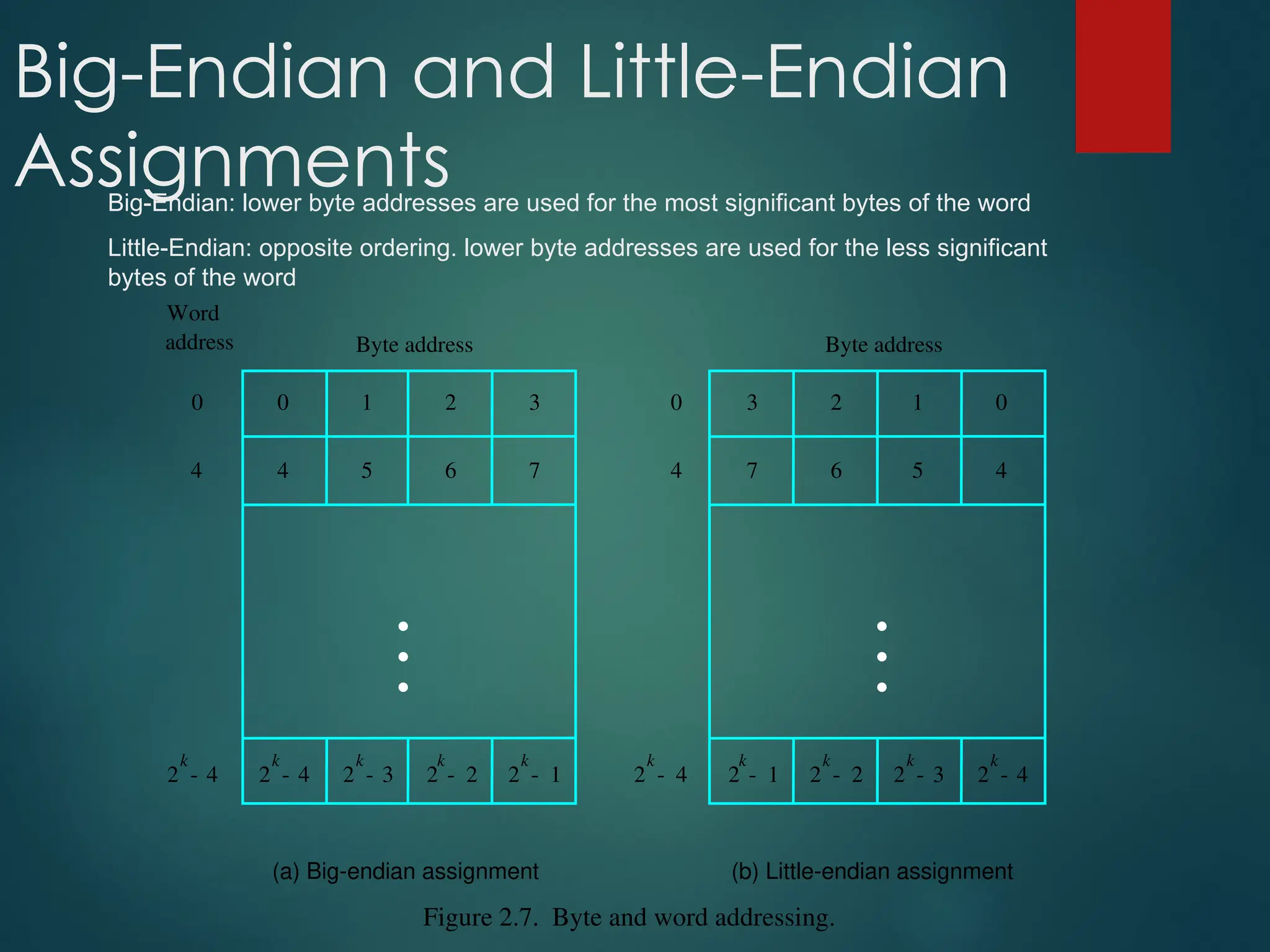
Figure 2.7. Byte and word addressing.
Big-Endian: lower byte addresses are used for the most significant bytes of the word
Little-Endian: opposite ordering. lower byte addresses are used for the less significant
bytes of the word
60.
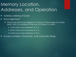
Memory Location,
Addresses, andOperation
Address ordering of bytes
Word alignment
Words are said to be aligned in memory if they begin at a byte
addr. that is a multiple of the num of bytes in a word.
16-bit word: word addresses: 0, 2, 4,….
32-bit word: word addresses: 0, 4, 8,….
64-bit word: word addresses: 0, 8,16,….
Access numbers, characters, and character strings
61.
Memory Operation
Load(or Read or Fetch)
Copy the content. The memory content doesn’t
change.
Address – Load
Registers can be used
Store (or Write)
Overwrite the content in memory
Address and Data – Store
Registers can be used
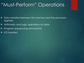
“Must-Perform” Operations
Datatransfers between the memory and the processor
registers
Arithmetic and logic operations on data
Program sequencing and control
I/O transfers
64.
Register Transfer Notation
Identify a location by a symbolic name standing for its
hardware binary address (LOC, R0,…)
Contents of a location are denoted by placing square
brackets around the name of the location (R1←[LOC], R3
←[R1]+[R2])
Register Transfer Notation (RTN)
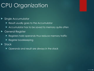
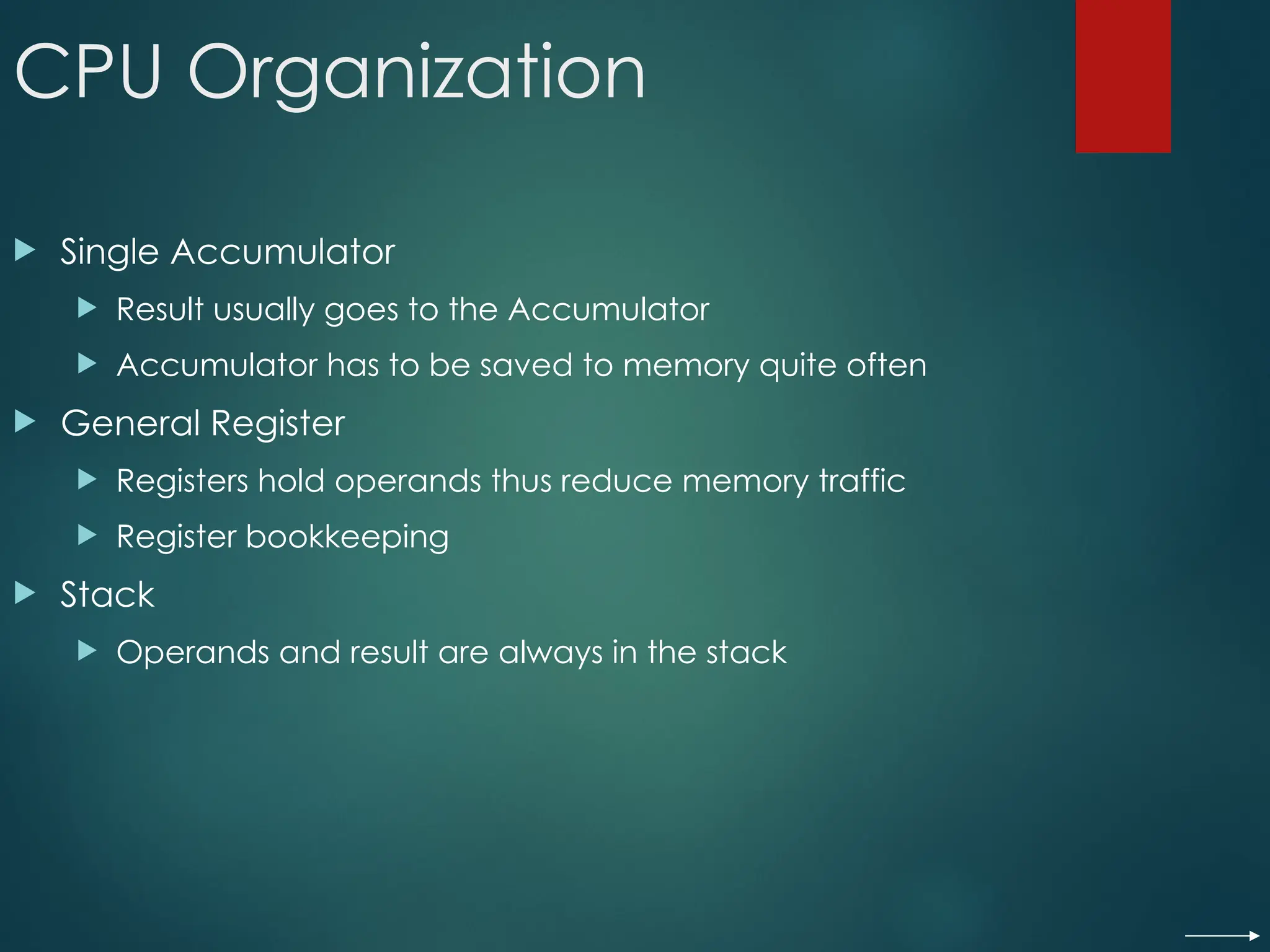
CPU Organization
SingleAccumulator
Result usually goes to the Accumulator
Accumulator has to be saved to memory quite often
General Register
Registers hold operands thus reduce memory traffic
Register bookkeeping
Stack
Operands and result are always in the stack
67.
Instruction Formats
Three-AddressInstructions
ADD R1, R2, R3 R1 ← R2 + R3
Two-Address Instructions
ADD R1, R2 R1 ← R1 + R2
One-Address Instructions
ADD M AC ← AC + M[AR]
Zero-Address Instructions
ADD TOS ← TOS + (TOS – 1)
RISC Instructions
Lots of registers. Memory is restricted to Load & Store
Opcode Operand(s) or Address(es)
Instruction Formats
Example: Evaluate(A+B) (C+D)
One-Address
1. LOAD A ; AC ← M[A]
2. ADD B ; AC ← AC + M[B]
3. STORE T ; M[T] ← AC
4. LOAD C ; AC ← M[C]
5. ADD D ; AC ← AC + M[D]
6. MUL T ; AC ← AC M[T]
7. STORE X ; M[X] ← AC
71.
Instruction Formats
Example: Evaluate(A+B) (C+D)
Zero-Address
1. PUSH A ; TOS ← A
2. PUSH B ; TOS ← B
3. ADD ; TOS ← (A + B)
4. PUSH C ; TOS ← C
5. PUSH D ; TOS ← D
6. ADD ; TOS ← (C + D)
7. MUL ; TOS ←
(C+D)(A+B)
8. POP X ; M[X] ← TOS
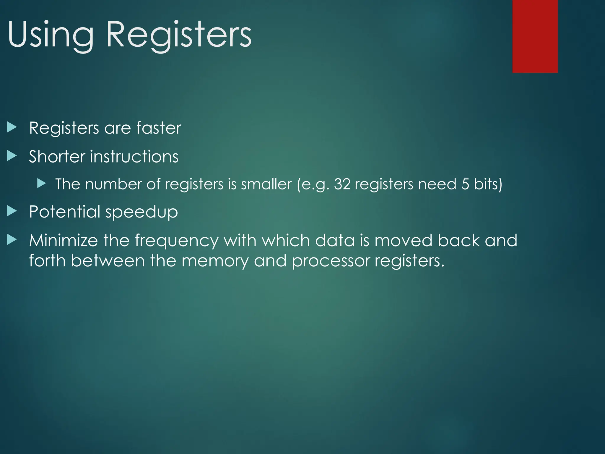
Using Registers
Registersare faster
Shorter instructions
The number of registers is smaller (e.g. 32 registers need 5 bits)
Potential speedup
Minimize the frequency with which data is moved back and
forth between the memory and processor registers.
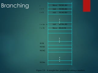
74.
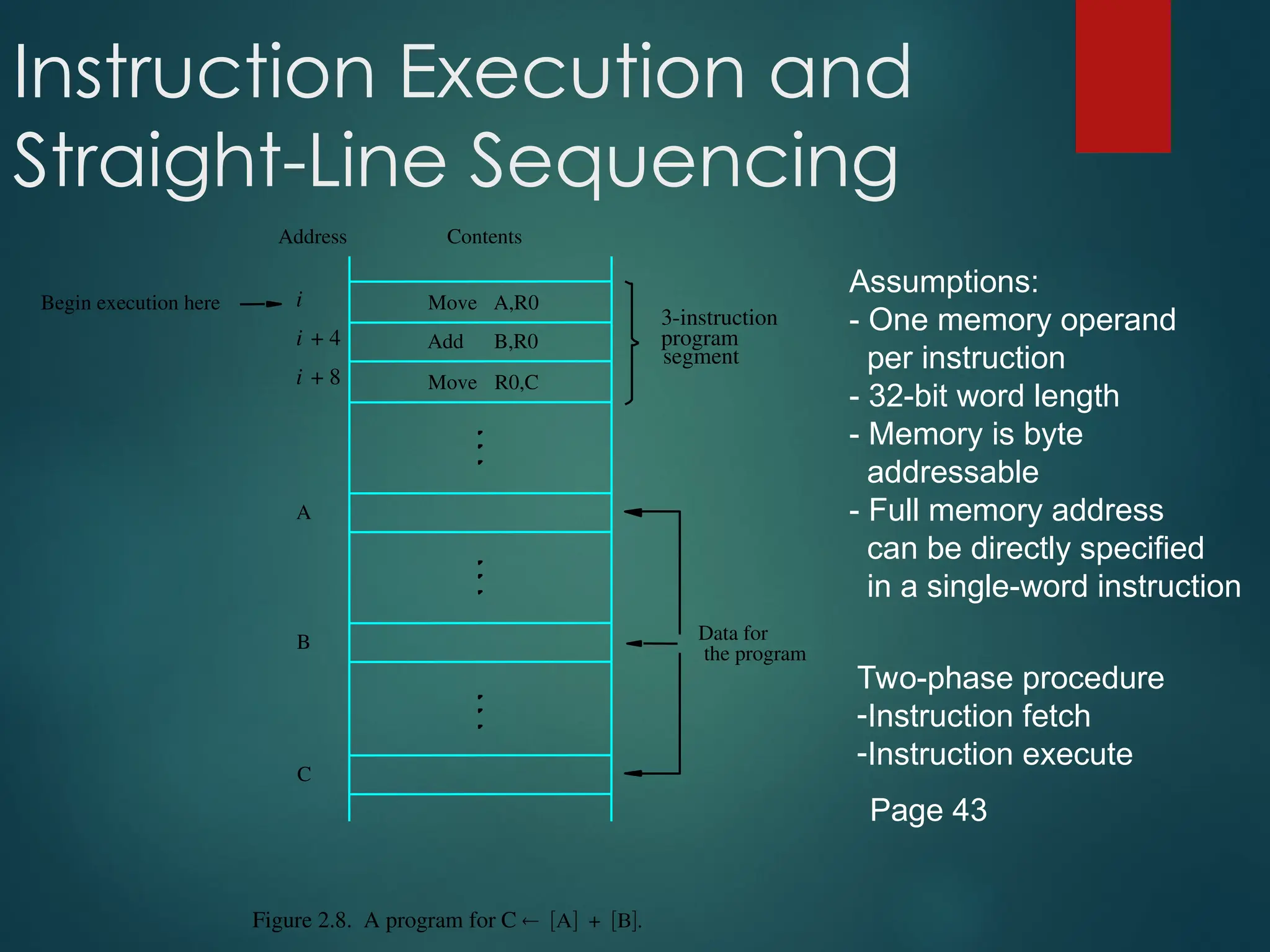
Instruction Execution and
Straight-LineSequencing
R0,C
B,R0
A,R0
Move
i + 8
Begin execution here Move
i
Contents
Address
C
B
A
the program
Data for
segment
program
3-instruction
Add
i + 4
Figure 2.8. A program for C +
Assumptions:
- One memory operand
per instruction
- 32-bit word length
- Memory is byte
addressable
- Full memory address
can be directly specified
in a single-word instruction
Two-phase procedure
-Instruction fetch
-Instruction execute
Page 43
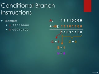
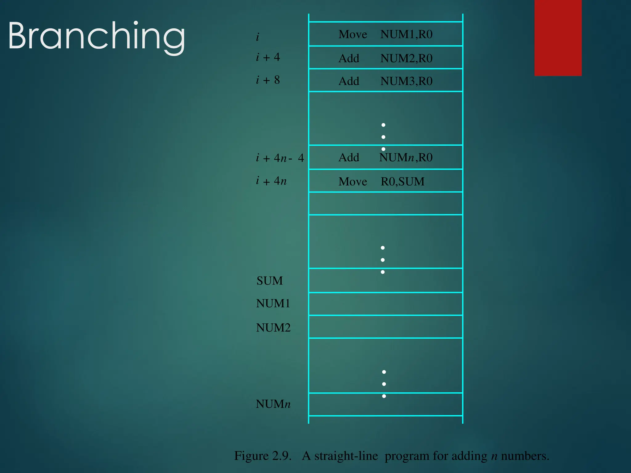
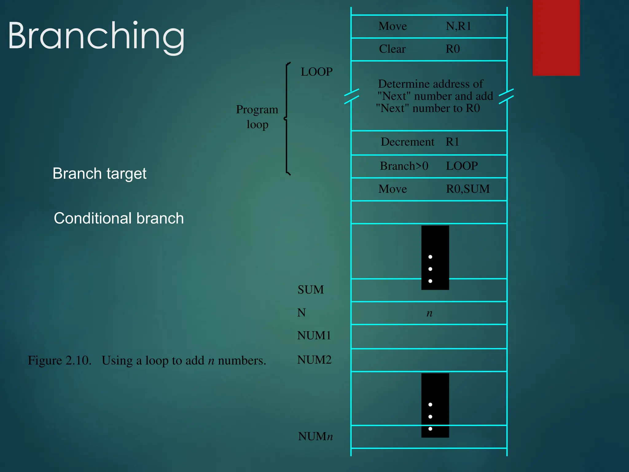
Branching N,R1
Move
NUMn
NUM2
NUM1
R0,SUM
R1
"Next" numberto R0
Figure 2.10. Using a loop to add n numbers.
LOOP
Decrement
Move
LOOP
loop
Program
Determine address of
"Next" number and add
N
SUM
n
R0
Clear
Branch>0
•
•
•
•
•
•
Branch target
Conditional branch
77.
Condition Codes
Conditioncode flags
Condition code register / status register
N (negative)
Z (zero)
V (overflow)
C (carry)
Different instructions affect different flags
Generating Memory
Addresses
Howto specify the address of branch target?
Can we give the memory operand address directly in a single
Add instruction in the loop?
Use a register to hold the address of NUM1; then increment by
4 on each pass through the loop.
82.
Addressing Modes
Implied
AC is implied in “ADD M[AR]” in “One-Address” instr.
TOS is implied in “ADD” in “Zero-Address” instr.
Immediate
The use of a constant in “MOV R1, 5”, i.e. R1 ← 5
Register
Indicate which register holds the operand
Opcode Mode ...
83.
Addressing Modes
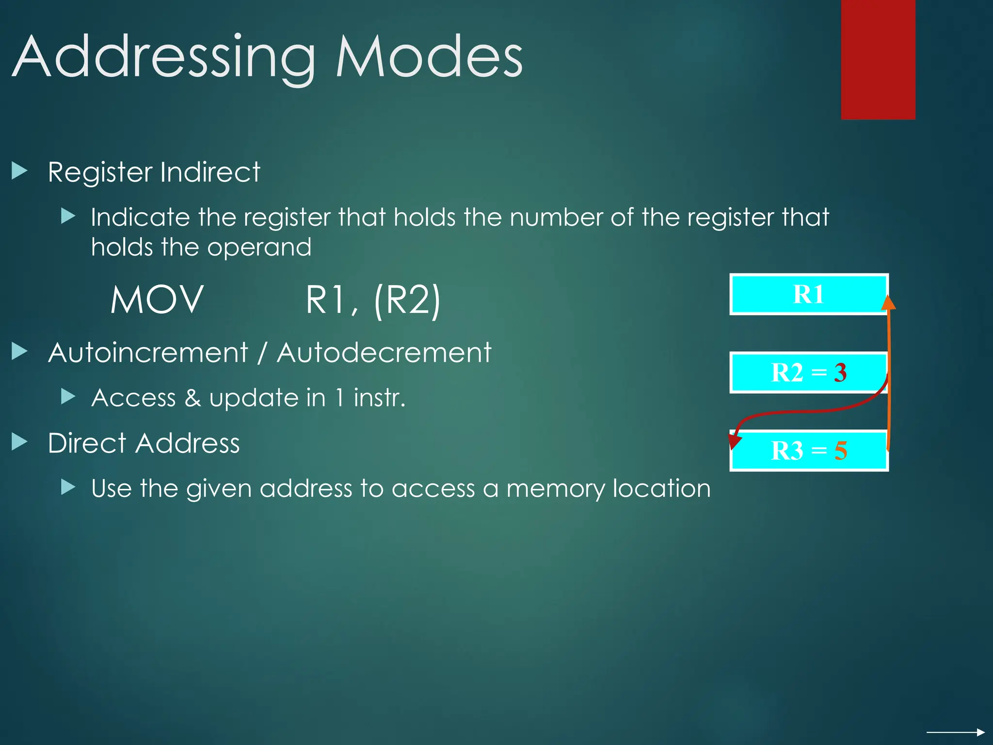
RegisterIndirect
Indicate the register that holds the number of the register that
holds the operand
MOV R1, (R2)
Autoincrement / Autodecrement
Access & update in 1 instr.
Direct Address
Use the given address to access a memory location
R1
R2 = 3
R3 = 5
84.
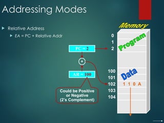
Addressing Modes
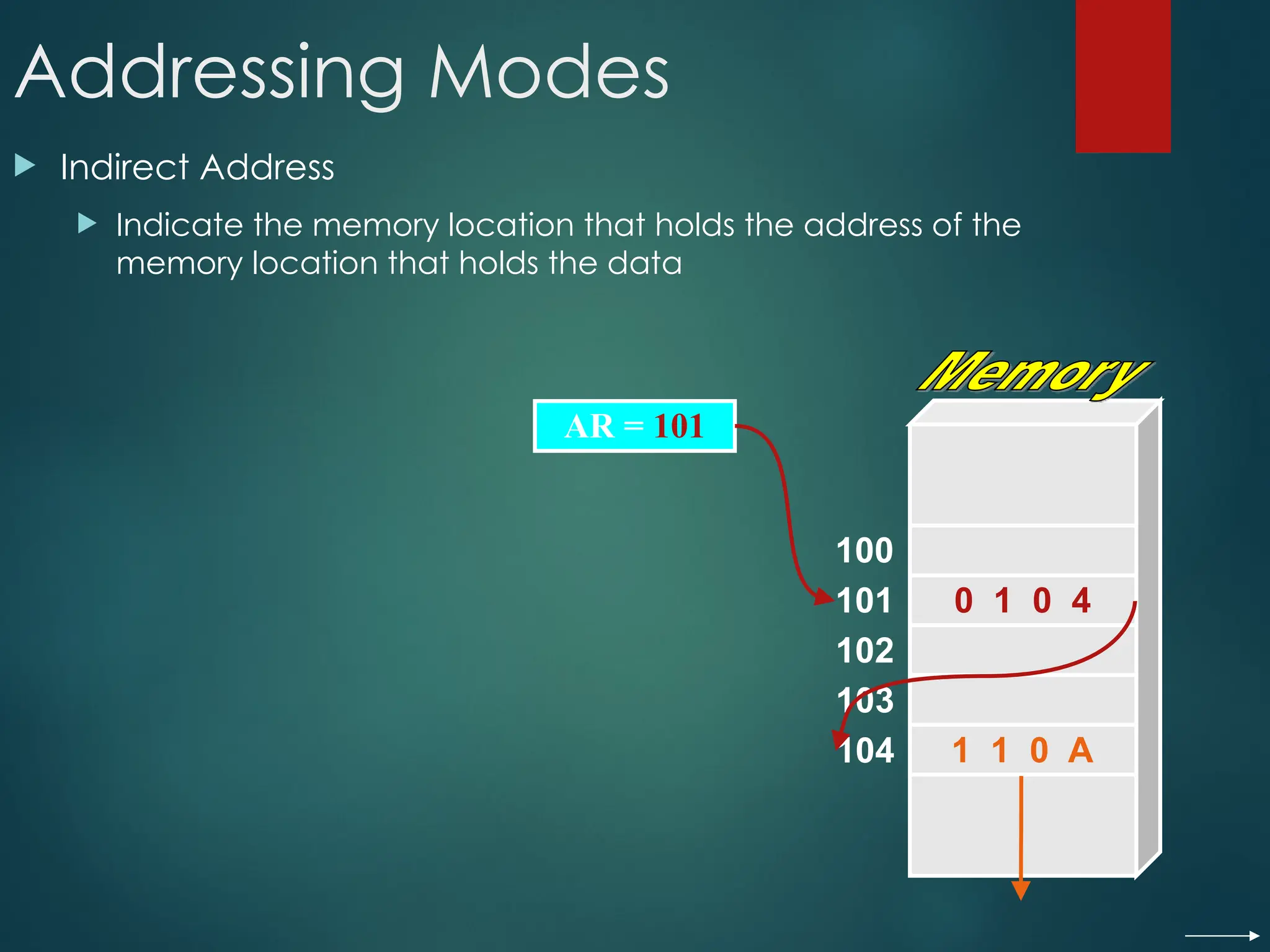
IndirectAddress
Indicate the memory location that holds the address of the
memory location that holds the data
AR = 101
100
101
102
103
104
0 1 0 4
1 1 0 A
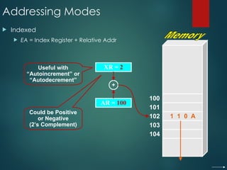
Addressing Modes
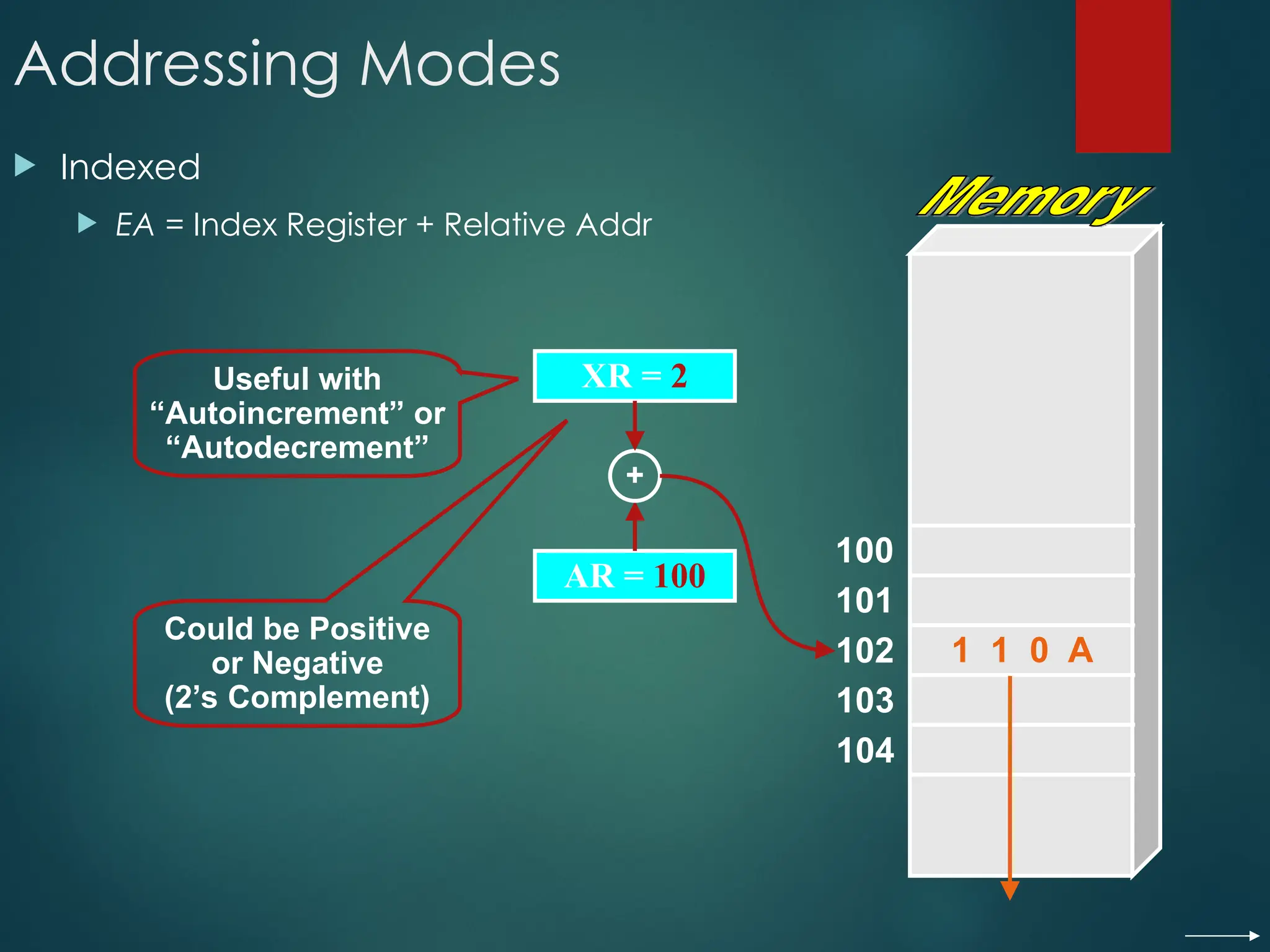
Indexed
EA = Index Register + Relative Addr
100
101
102
103
104
AR = 100
1 1 0 A
XR = 2
+
Could be Positive
or Negative
(2’s Complement)
Useful with
“Autoincrement” or
“Autodecrement”
87.
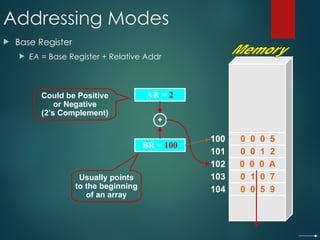
Addressing Modes
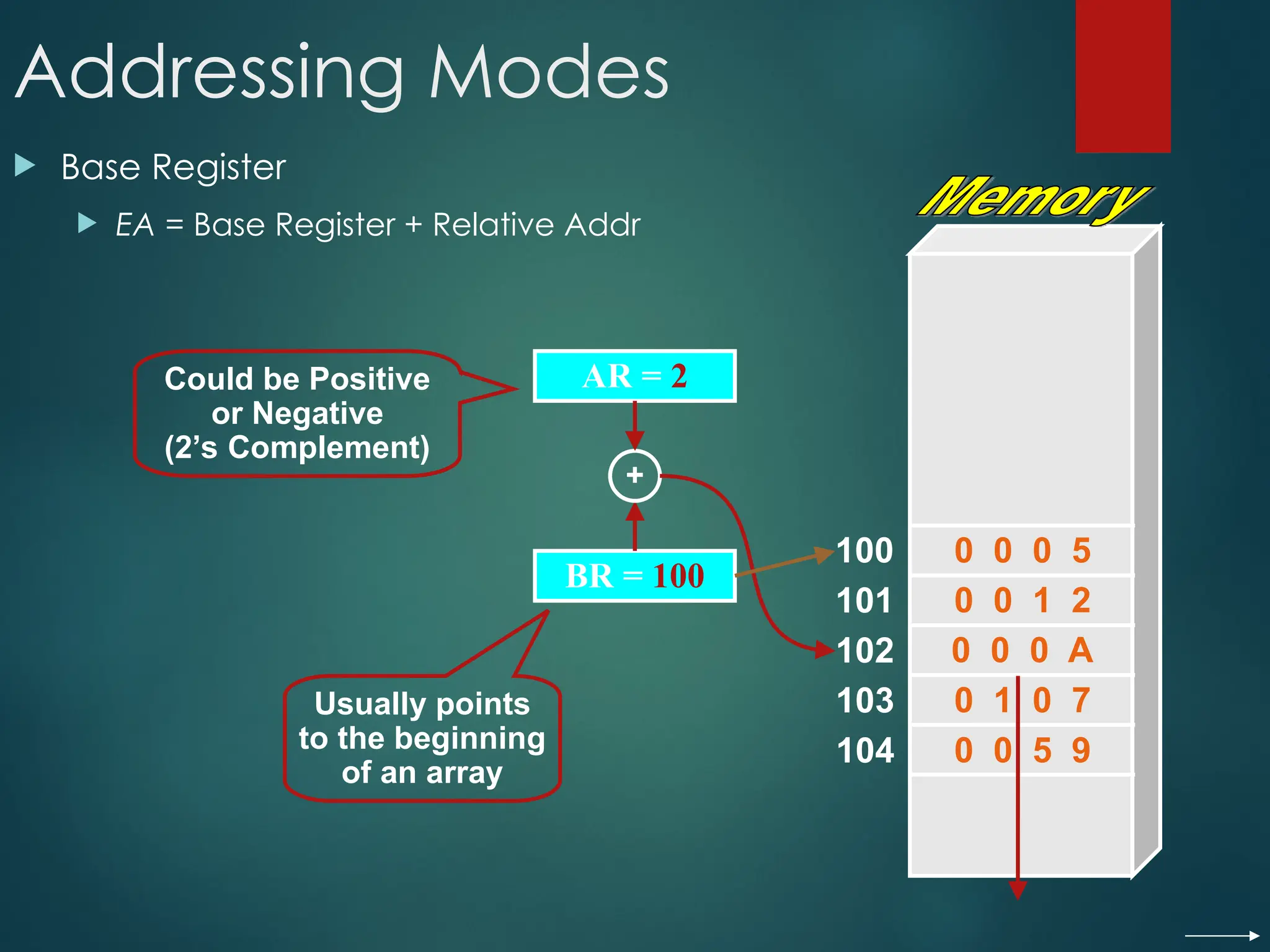
BaseRegister
EA = Base Register + Relative Addr
100
101
102
103
104
BR = 100
0 0 0 A
AR = 2
+
Could be Positive
or Negative
(2’s Complement)
Usually points
to the beginning
of an array
0 0 0 5
0 0 1 2
0 1 0 7
0 0 5 9
88.
Addressing Modes
Thedifferent
ways in
which the
location of
an operand
is specified
in an
instruction
are referred
to as
addressing
modes.
Name Assembler syntax Addressingfunction
Immediate #Value Operand= Value
Register Ri EA = Ri
Absolute(Direct) LOC EA = LOC
Indirect (Ri ) EA = [Ri]
(LOC) EA = [LOC]
Index X(R i) EA = [Ri] + X
Basewith index (Ri ,Rj ) EA = [Ri] + [Rj]
Basewith index X(R i,Rj ) EA = [Ri] + [Rj] + X
andoffset
Relative X(PC) EA = [PC] + X
Autoincremen
t (Ri )+ EA = [Ri] ;
Incremen
t Ri
Autodecrement (Ri ) Decremen
t Ri ;
EA = [Ri]
89.
Indexing and Arrays
Index mode – the effective address of the
operand is generated by adding a constant
value to the contents of a register.
Index register
X(Ri): EA = X + [Ri]
The constant X may be given either as an
explicit number or as a symbolic name
representing a numerical value.
If X is shorter than a word, sign-extension is
needed.
90.
Indexing and Arrays
In general, the Index mode facilitates access to an operand
whose location is defined relative to a reference point within
the data structure in which the operand appears.
Several variations:
(Ri, Rj): EA = [Ri] + [Rj]
X(Ri, Rj): EA = X + [Ri] + [Rj]
91.
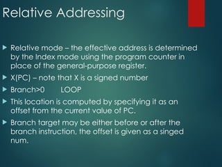
Relative Addressing
Relativemode – the effective address is determined
by the Index mode using the program counter in
place of the general-purpose register.
X(PC) – note that X is a signed number
Branch>0 LOOP
This location is computed by specifying it as an
offset from the current value of PC.
Branch target may be either before or after the
branch instruction, the offset is given as a singed
num.
92.
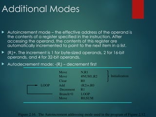
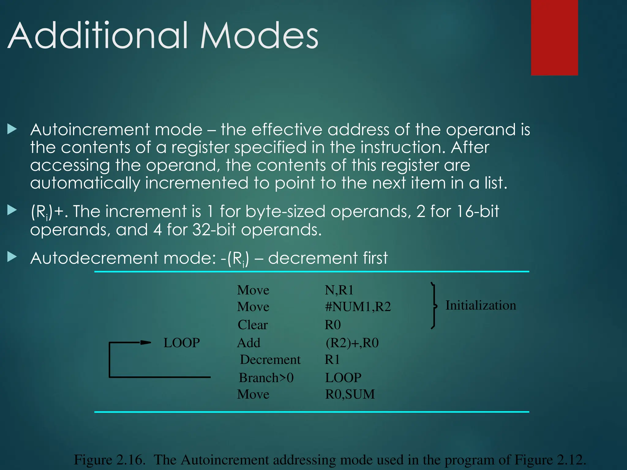
Additional Modes
Autoincrementmode – the effective address of the operand is
the contents of a register specified in the instruction. After
accessing the operand, the contents of this register are
automatically incremented to point to the next item in a list.
(Ri)+. The increment is 1 for byte-sized operands, 2 for 16-bit
operands, and 4 for 32-bit operands.
Autodecrement mode: -(Ri) – decrement first
R0
Clear
R0,SUM
R1
(R2)+,R0
Figure 2.16. The Autoincrement addressing mode used in the program of Figure 2.12.
Initialization
Move
LOOP Add
Decrement
LOOP
#NUM1,R2
N,R1
Move
Move
Branch>0
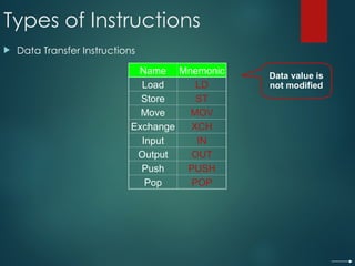
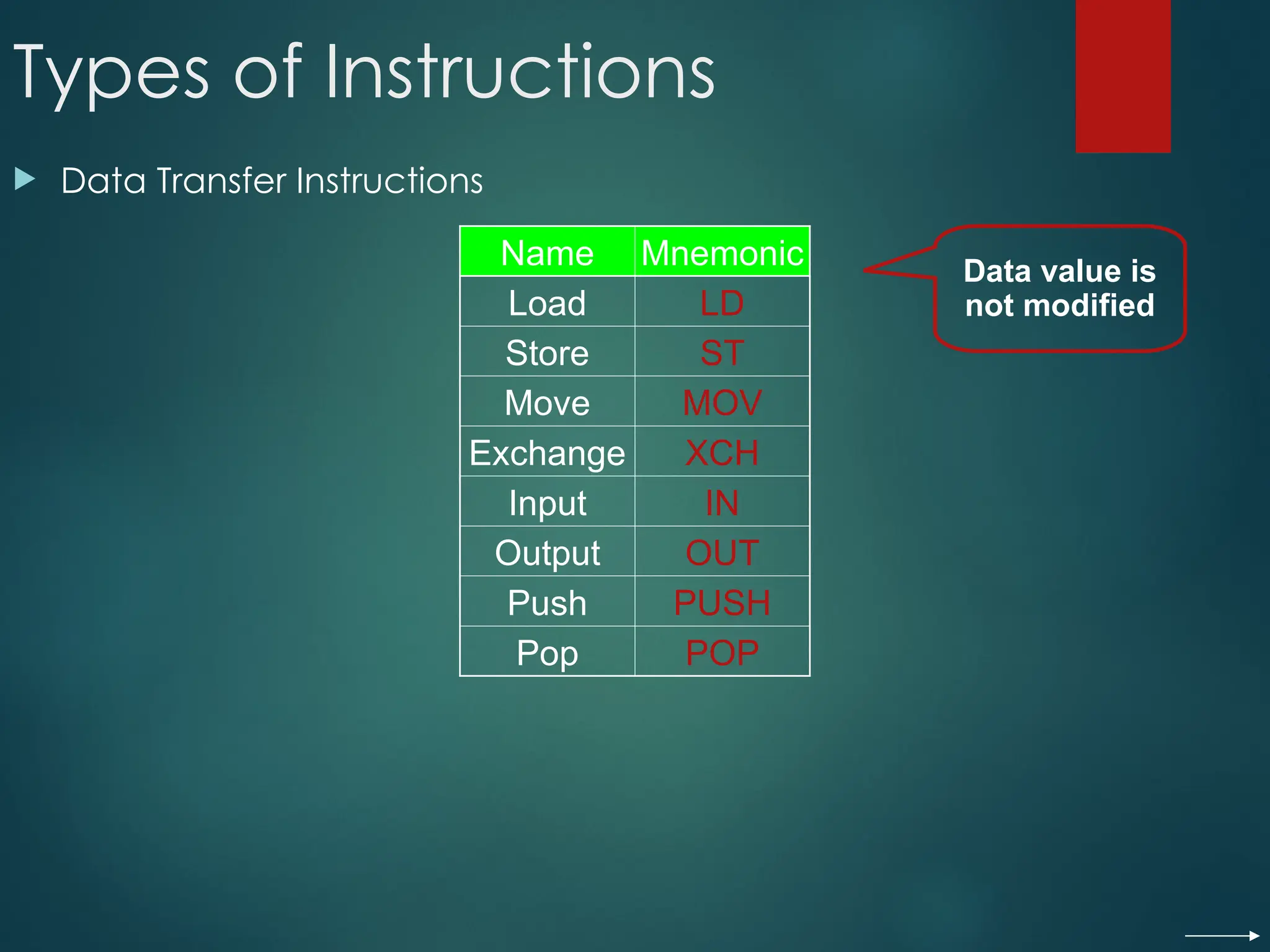
Types of Instructions
Data Transfer Instructions
Name Mnemonic
Load LD
Store ST
Move MOV
Exchange XCH
Input IN
Output OUT
Push PUSH
Pop POP
Data value is
not modified
95.
Data Transfer Instructions
ModeAssembly Register Transfer
Direct address LD ADR AC ← M[ADR]
Indirect address LD @ADR AC ← M[M[ADR]]
Relative address LD $ADR AC ← M[PC+ADR]
Immediate operand LD #NBR AC ← NBR
Index addressing LD ADR(X) AC ← M[ADR+XR]
Register LD R1 AC ← R1
Register indirect LD (R1) AC ← M[R1]
Autoincrement LD (R1)+ AC ← M[R1], R1 ← R1+1
96.
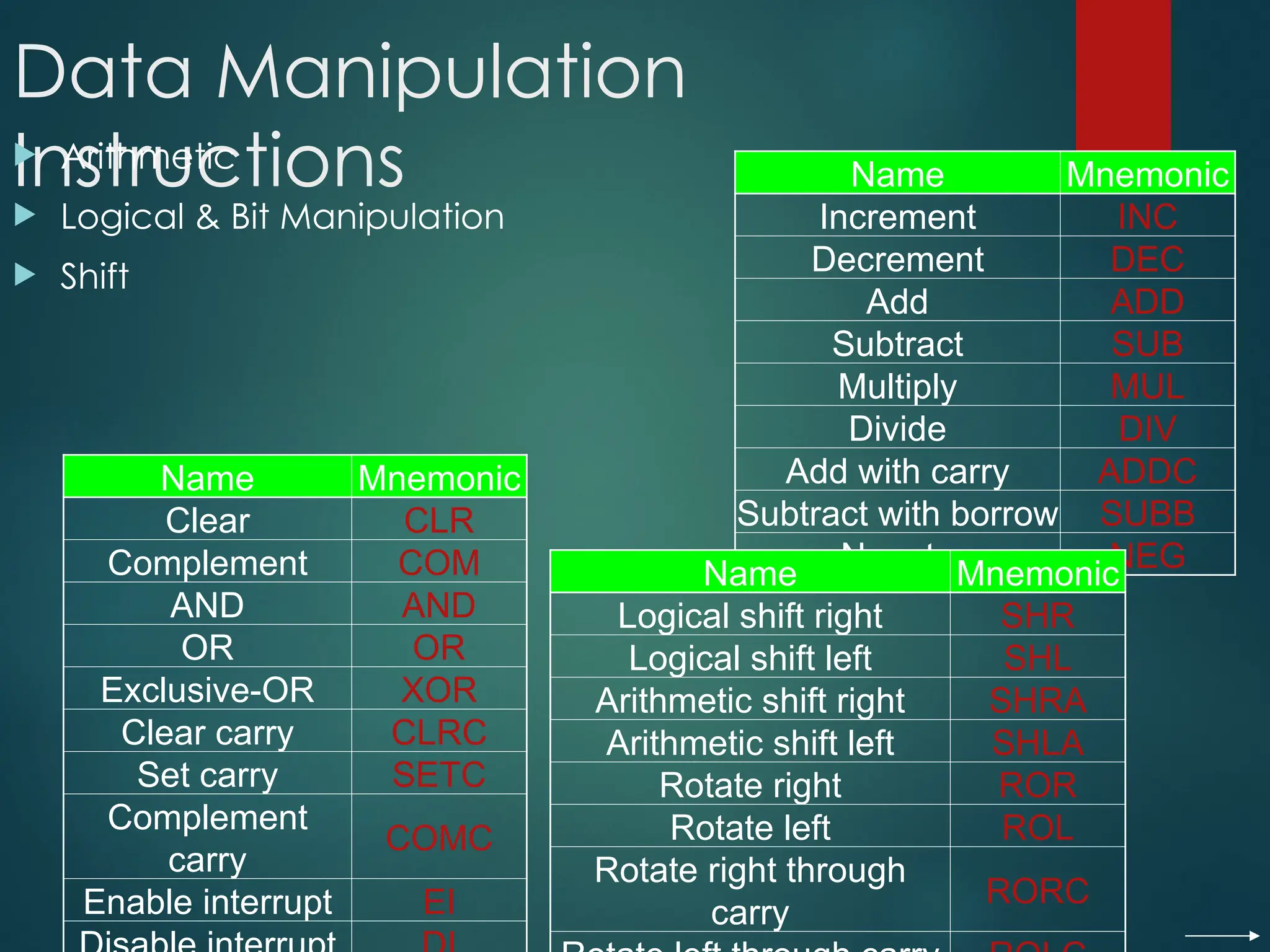
Data Manipulation
Instructions
Arithmetic
Logical & Bit Manipulation
Shift
Name Mnemonic
Increment INC
Decrement DEC
Add ADD
Subtract SUB
Multiply MUL
Divide DIV
Add with carry ADDC
Subtract with borrow SUBB
Negate NEG
Name Mnemonic
Clear CLR
Complement COM
AND AND
OR OR
Exclusive-OR XOR
Clear carry CLRC
Set carry SETC
Complement
carry
COMC
Enable interrupt EI
Name Mnemonic
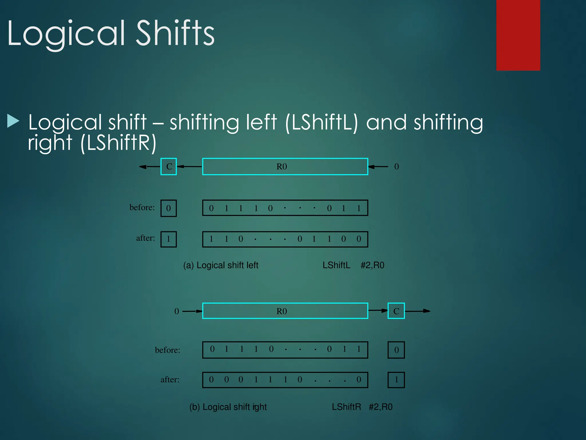
Logical shift right SHR
Logical shift left SHL
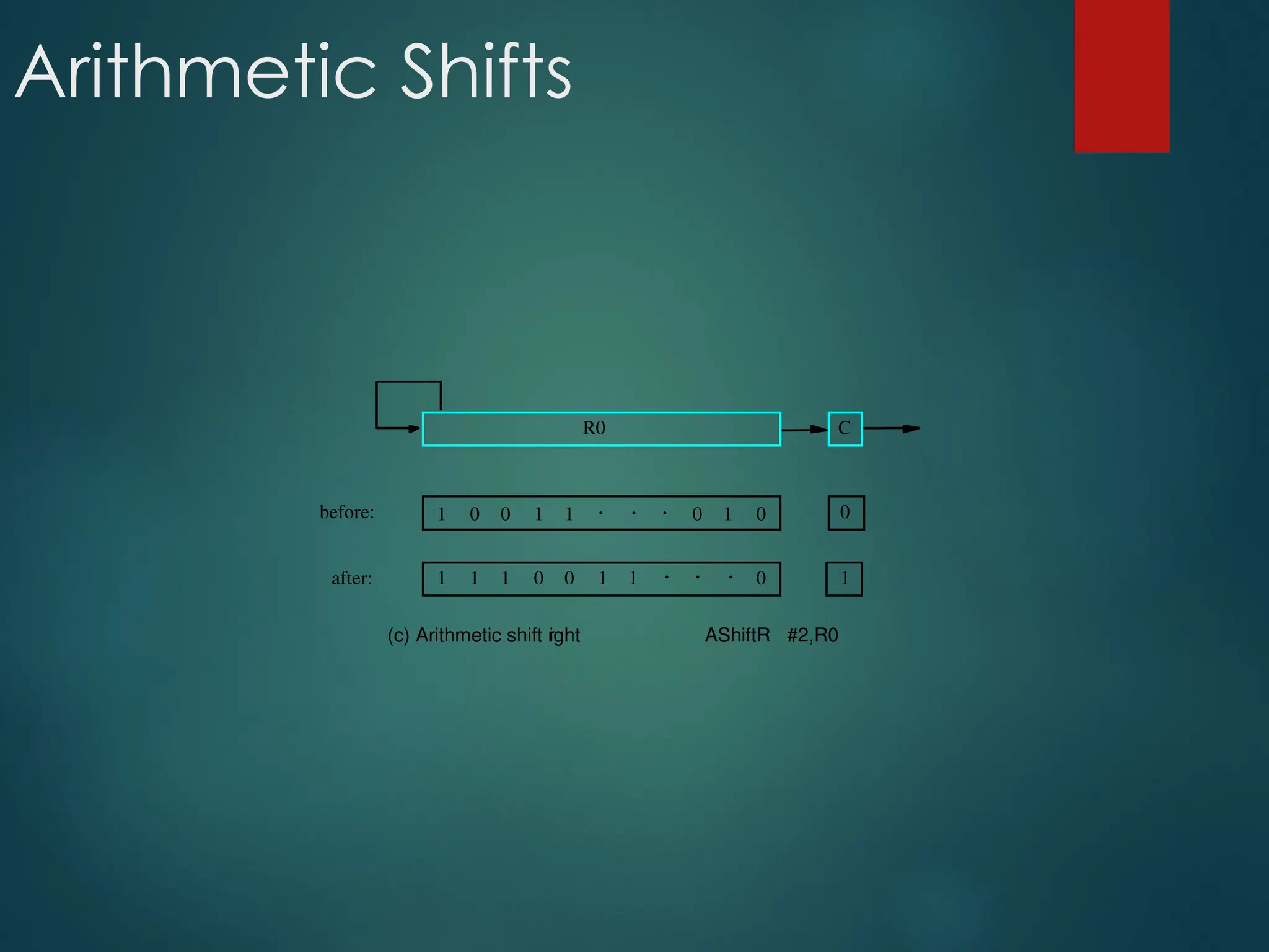
Arithmetic shift right SHRA
Arithmetic shift left SHLA
Rotate right ROR
Rotate left ROL
Rotate right through
carry
RORC
97.
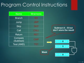
Program Control Instructions
NameMnemonic
Branch BR
Jump JMP
Skip SKP
Call CALL
Return RET
Compare
(Subtract)
CMP
Test (AND) TST
Subtract A – B but
don’t store the result
1 0 1 1 0 0 0 1
0 0 0 0 1 0 0 0
0 0 0 0 0 0 0 0
Mask
98.
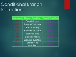
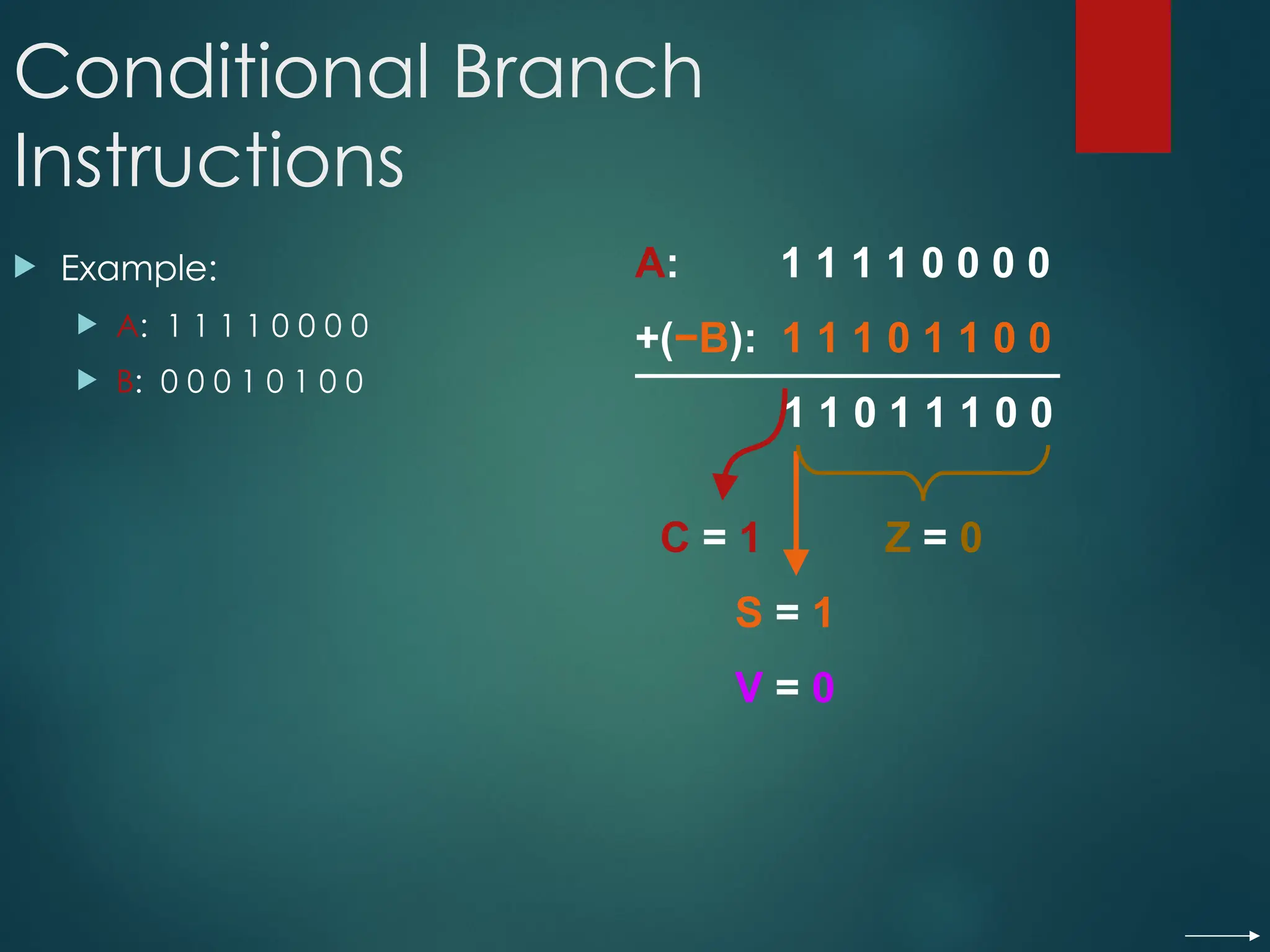
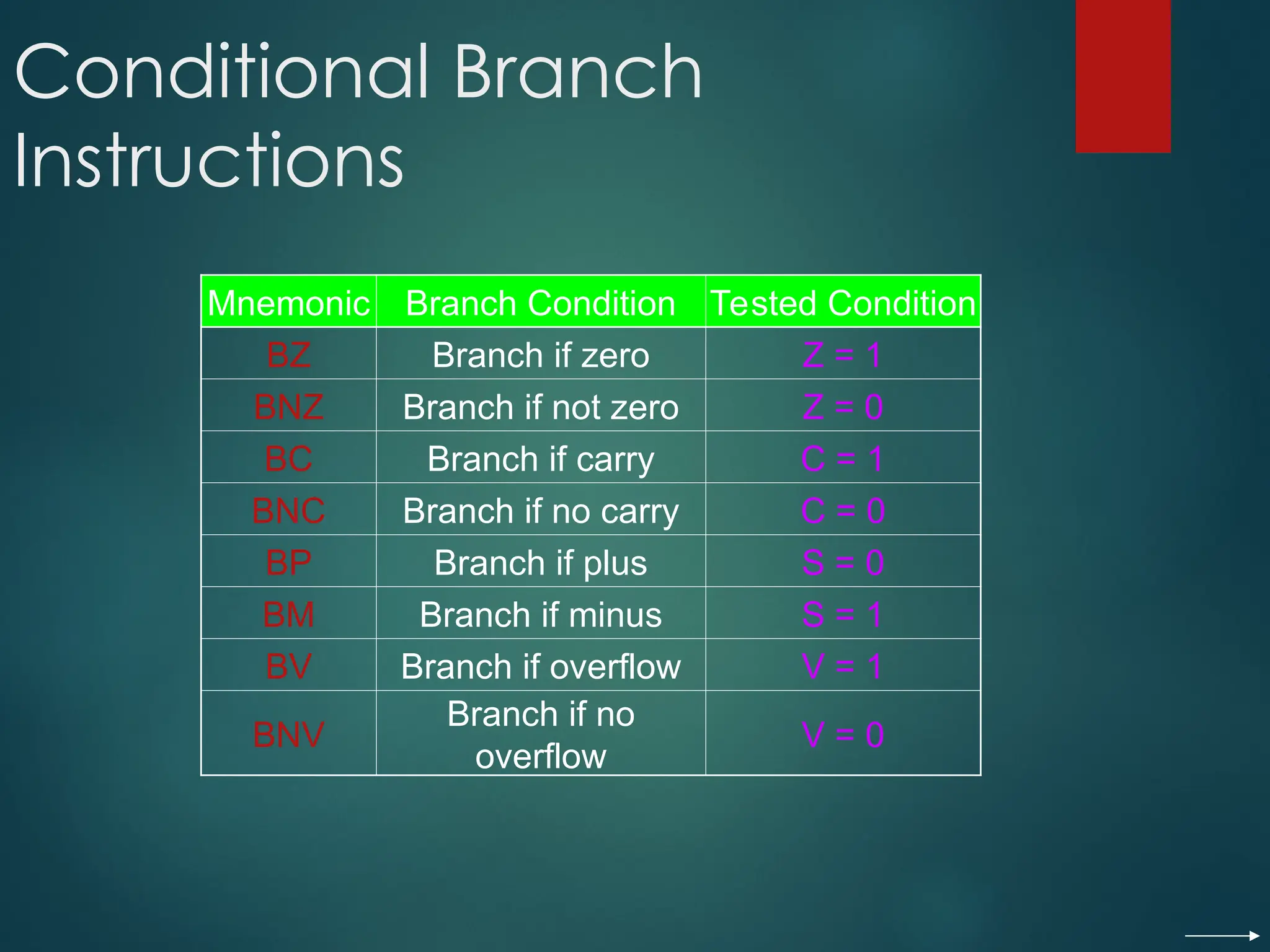
Conditional Branch
Instructions
Mnemonic BranchCondition Tested Condition
BZ Branch if zero Z = 1
BNZ Branch if not zero Z = 0
BC Branch if carry C = 1
BNC Branch if no carry C = 0
BP Branch if plus S = 0
BM Branch if minus S = 1
BV Branch if overflow V = 1
BNV
Branch if no
overflow
V = 0
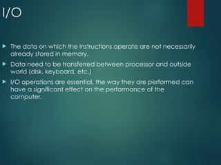
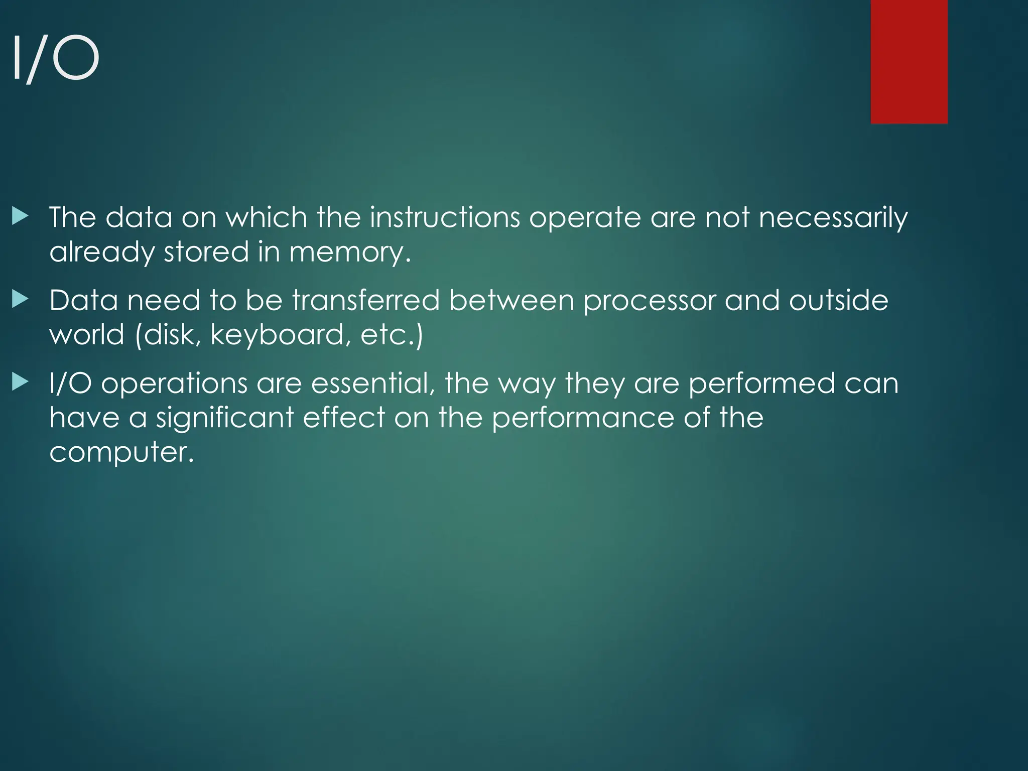
I/O
The dataon which the instructions operate are not necessarily
already stored in memory.
Data need to be transferred between processor and outside
world (disk, keyboard, etc.)
I/O operations are essential, the way they are performed can
have a significant effect on the performance of the
computer.
101.
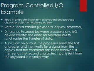
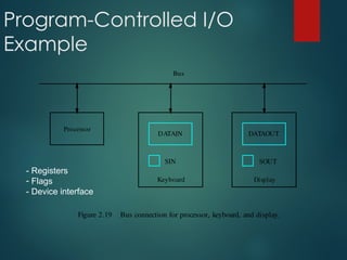
Program-Controlled I/O
Example
Readin character input from a keyboard and produce
character output on a display screen.
Rate of data transfer (keyboard, display, processor)
Difference in speed between processor and I/O
device creates the need for mechanisms to
synchronize the transfer of data.
A solution: on output, the processor sends the first
character and then waits for a signal from the
display that the character has been received. It
then sends the second character. Input is sent from
the keyboard in a similar way.
Program-Controlled I/O
Example
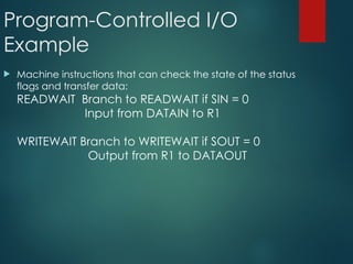
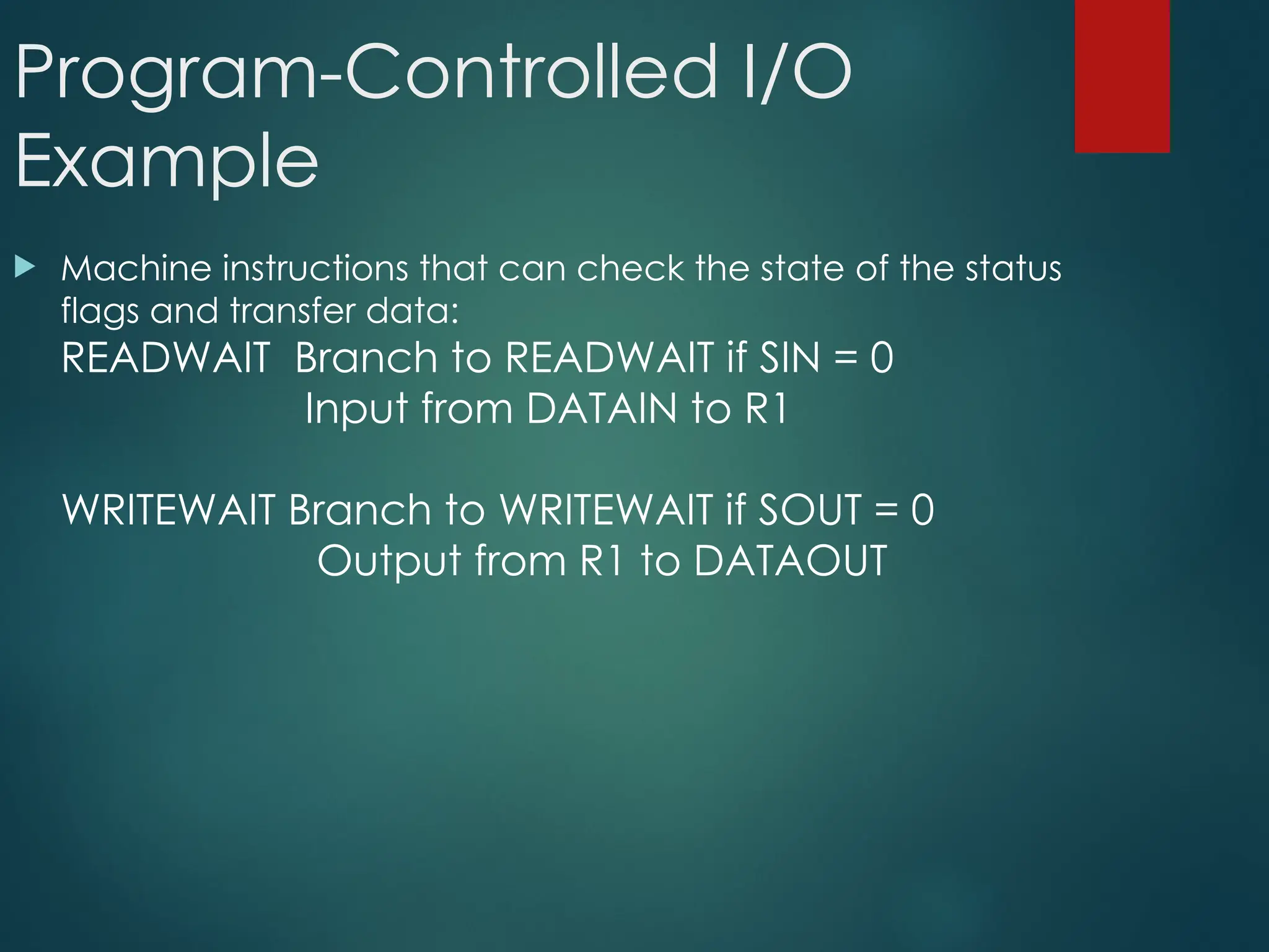
Machineinstructions that can check the state of the status
flags and transfer data:
READWAIT Branch to READWAIT if SIN = 0
Input from DATAIN to R1
WRITEWAIT Branch to WRITEWAIT if SOUT = 0
Output from R1 to DATAOUT
104.
Program-Controlled I/O
Example
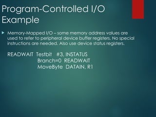
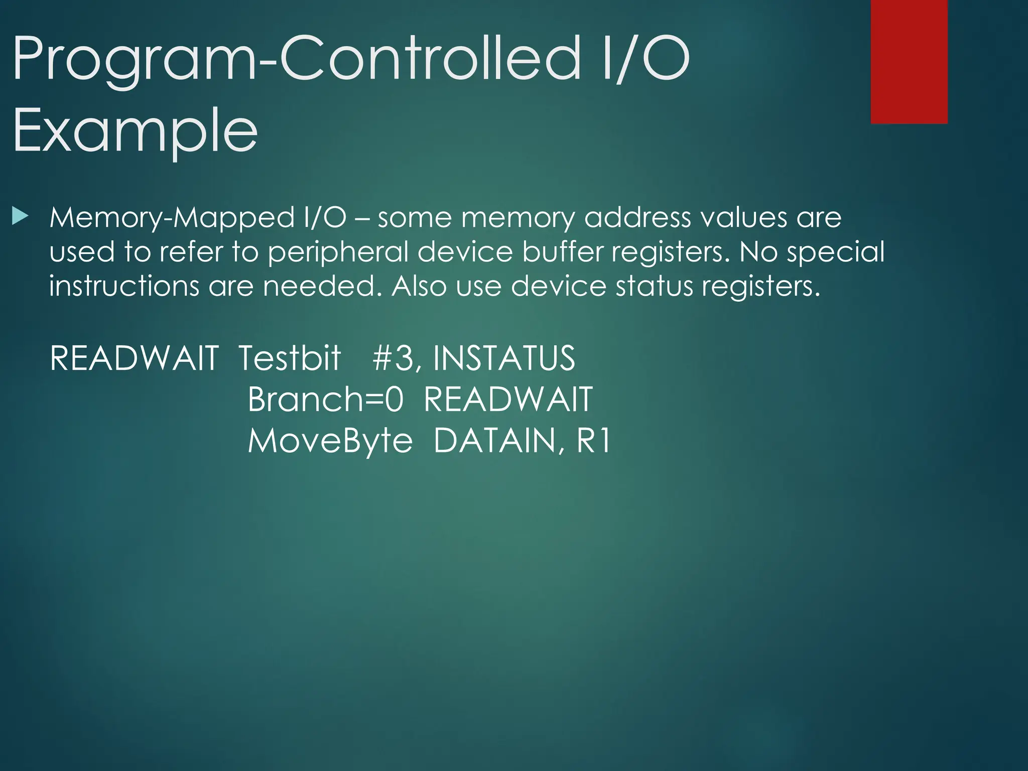
Memory-MappedI/O – some memory address values are
used to refer to peripheral device buffer registers. No special
instructions are needed. Also use device status registers.
READWAIT Testbit #3, INSTATUS
Branch=0 READWAIT
MoveByte DATAIN, R1
105.
Program-Controlled I/O
Example
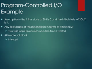
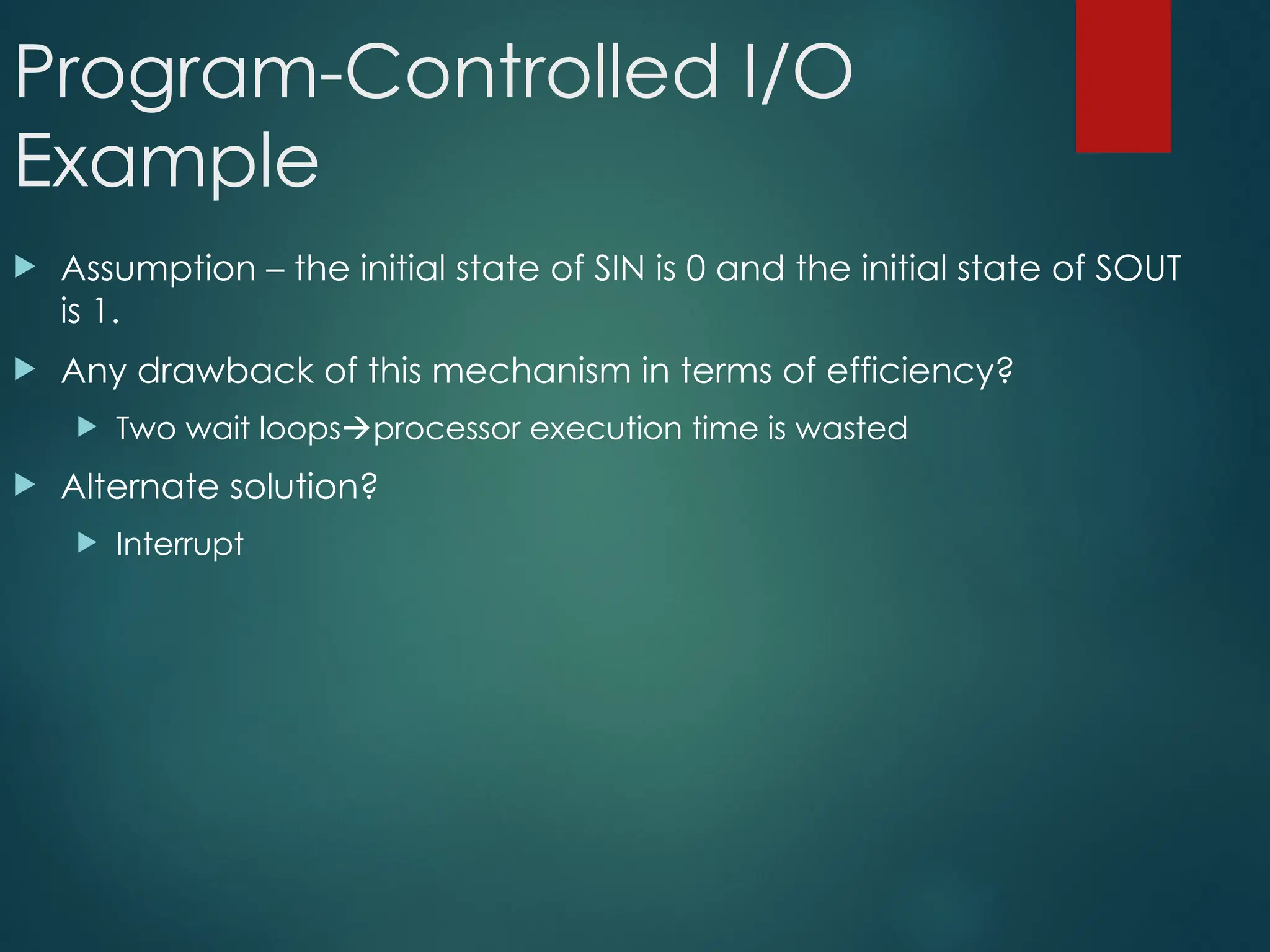
Assumption– the initial state of SIN is 0 and the initial state of SOUT
is 1.
Any drawback of this mechanism in terms of efficiency?
Two wait loopsprocessor execution time is wasted
Alternate solution?
Interrupt
Home Work
Foreach Addressing modes mentioned before, state one
example for each addressing mode stating the specific
benefit for using such addressing mode for such an
application.
108.
Stack Organization
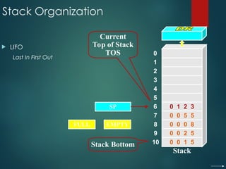
LIFO
LastIn First Out
SP
Stack Bottom
Current
Top of Stack
TOS 0
1
2
3
4
7
8
9
10
5
6
Stack
0 0 5 5
0 0 0 8
0 0 2 5
0 0 1 5
0 1 2 3
FULL EMPTY
109.
Stack Organization
PUSH
SP← SP – 1
M[SP] ← DR
If (SP = 0) then (FULL ← 1)
EMPTY ← 0
SP
Stack Bottom
Current
Top of Stack
TOS 0
1
2
3
4
7
8
9
10
5
6
Stack
0 0 5 5
0 0 0 8
0 0 2 5
0 0 1 5
0 1 2 3
FULL EMPTY
1 6 9 0
1 6 9 0
Current
Top of Stack
TOS
110.
Stack Organization
POP
DR← M[SP]
SP ← SP + 1
If (SP = 11) then (EMPTY ← 1)
FULL ← 0
SP
Stack Bottom
Current
Top of Stack
TOS 0
1
2
3
4
7
8
9
10
5
6
Stack
0 0 5 5
0 0 0 8
0 0 2 5
0 0 1 5
0 1 2 3
FULL EMPTY
1 6 9 0
1 6 9 0
Current
Top of Stack
TOS
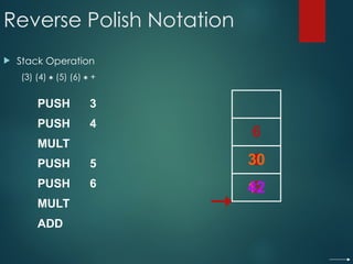
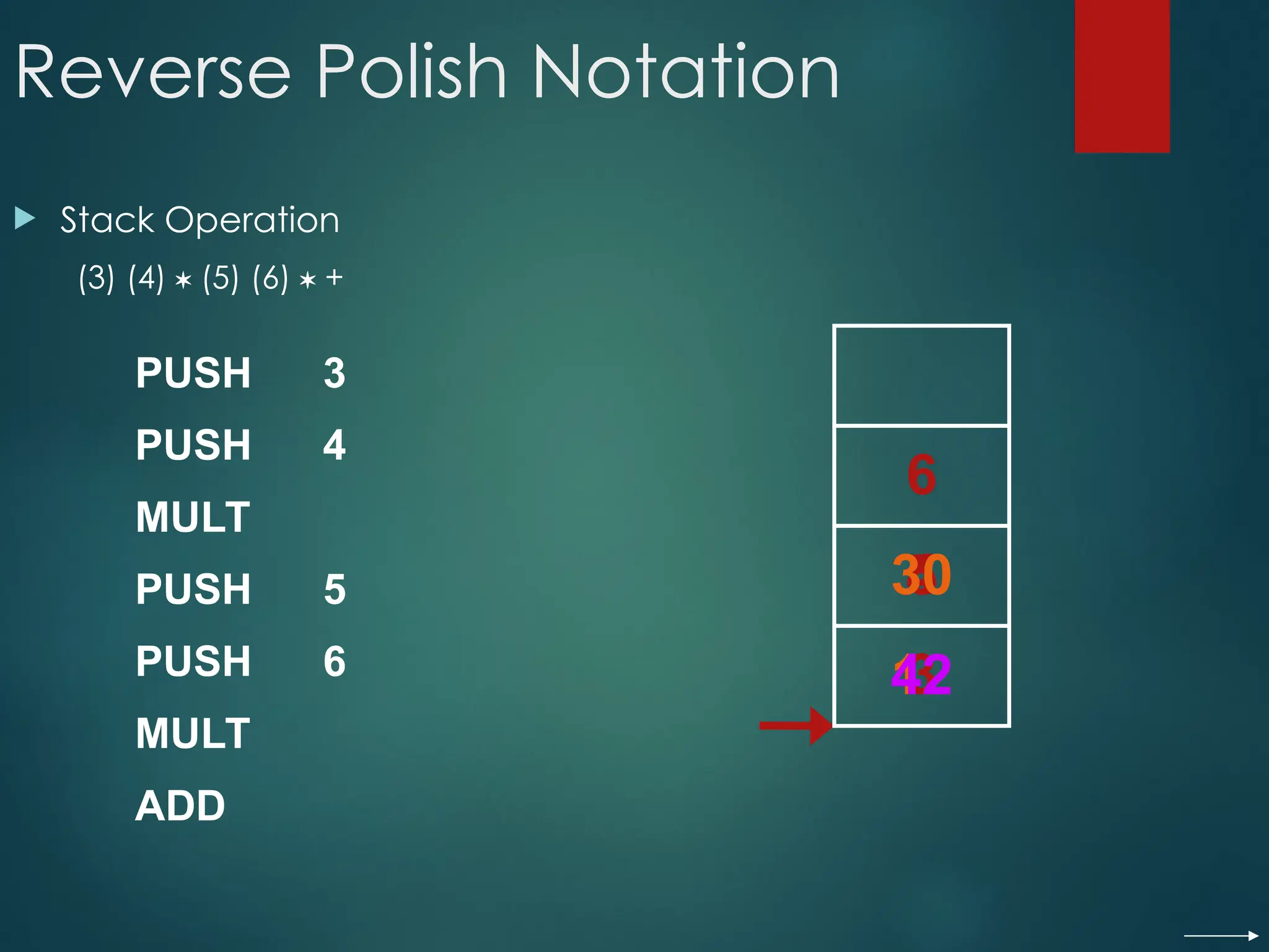
Reverse Polish Notation
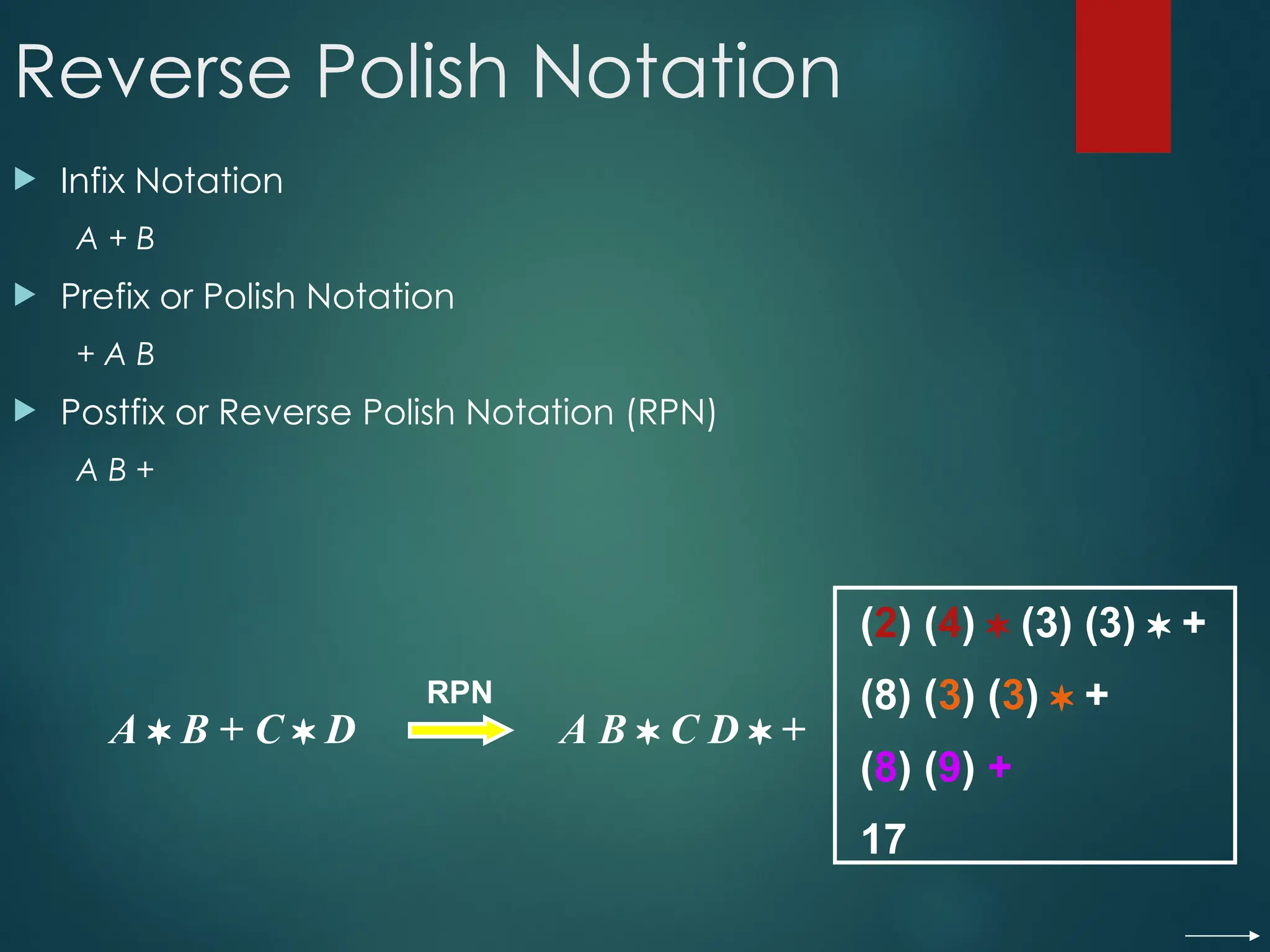
Infix Notation
A + B
Prefix or Polish Notation
+ A B
Postfix or Reverse Polish Notation (RPN)
A B +
A B + C D A B C D +
RPN
(2) (4) (3) (3) +
(8) (3) (3) +
(8) (9) +
17
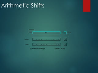
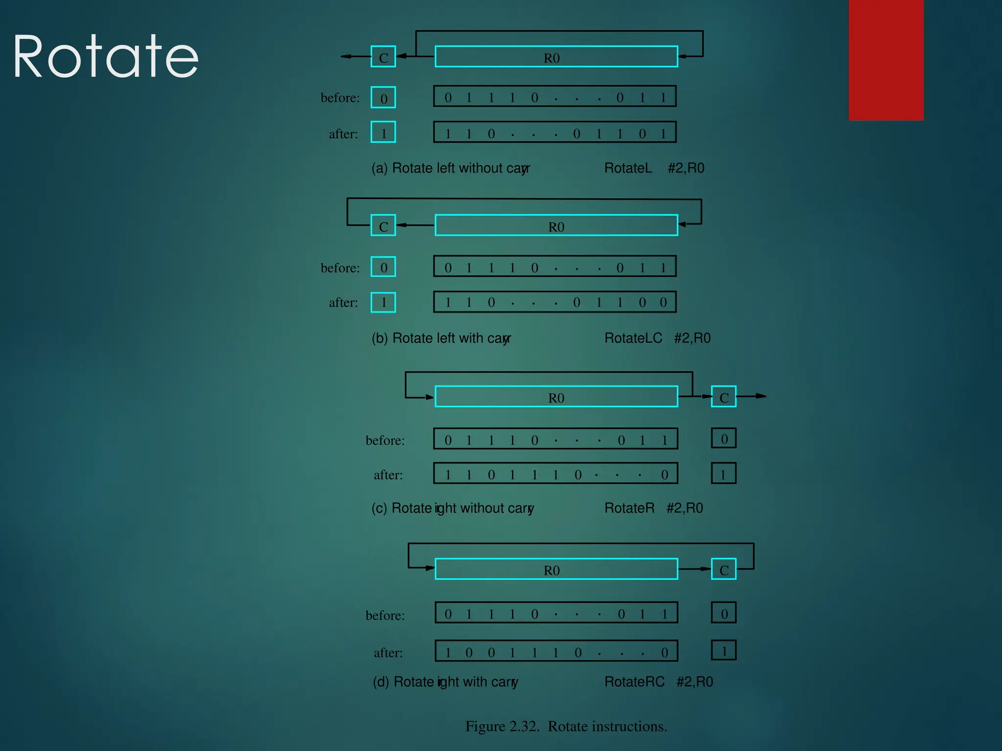
Rotate
Figure 2.32. Rotateinstructions.
C
R0
before:
after:
0
1
0 0 0
1 1 1 . . . 1
1
1 0 1 1 1 0
0
1
(c) Rotate r
ight without carr
y RotateR #2,R0
(a) Rotate left without carr
y RotateL #2,R0
C R0
before:
after:
0
1
0 0 0
1 1 1 . . . 1
1
1 1
0 . . . 1
0
1
0
1
C
before:
after:
0
1
0 0 0
1 1 1 . . . 1
1
1 0 1 1 1 0
0
0
(d) Rotate r
ight with carr
y RotateRC #2,R0
R0
. . .
. . .
(b) Rotate left with carr
y RotateLC #2,R0
C R0
before:
after:
0
1
0 0 0
1 1 1 . . . 1
1
1 1
0 . . . 0
0
1
0
1
119.
Multiplication and Division
Not very popular (especially division)
Multiply Ri, Rj
Rj ← [Ri] х [Rj]
2n-bit product case: high-order half in R(j+1)
Divide Ri, Rj
Rj ← [Ri] / [Rj]
Quotient is in Rj, remainder may be placed in R(j+1)
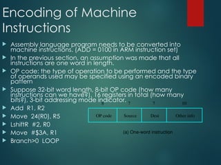
Encoding of Machine
Instructions
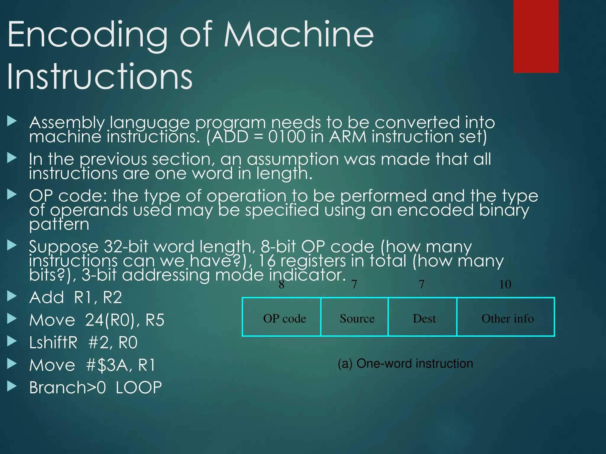
Assembly language program needs to be converted into
machine instructions. (ADD = 0100 in ARM instruction set)
In the previous section, an assumption was made that all
instructions are one word in length.
OP code: the type of operation to be performed and the type
of operands used may be specified using an encoded binary
pattern
Suppose 32-bit word length, 8-bit OP code (how many
instructions can we have?), 16 registers in total (how many
bits?), 3-bit addressing mode indicator.
Add R1, R2
Move 24(R0), R5
LshiftR #2, R0
Move #$3A, R1
Branch>0 LOOP
OP code Source Dest Other info
8 7 7 10
(a) One-word instruction
122.
Encoding of Machine
Instructions
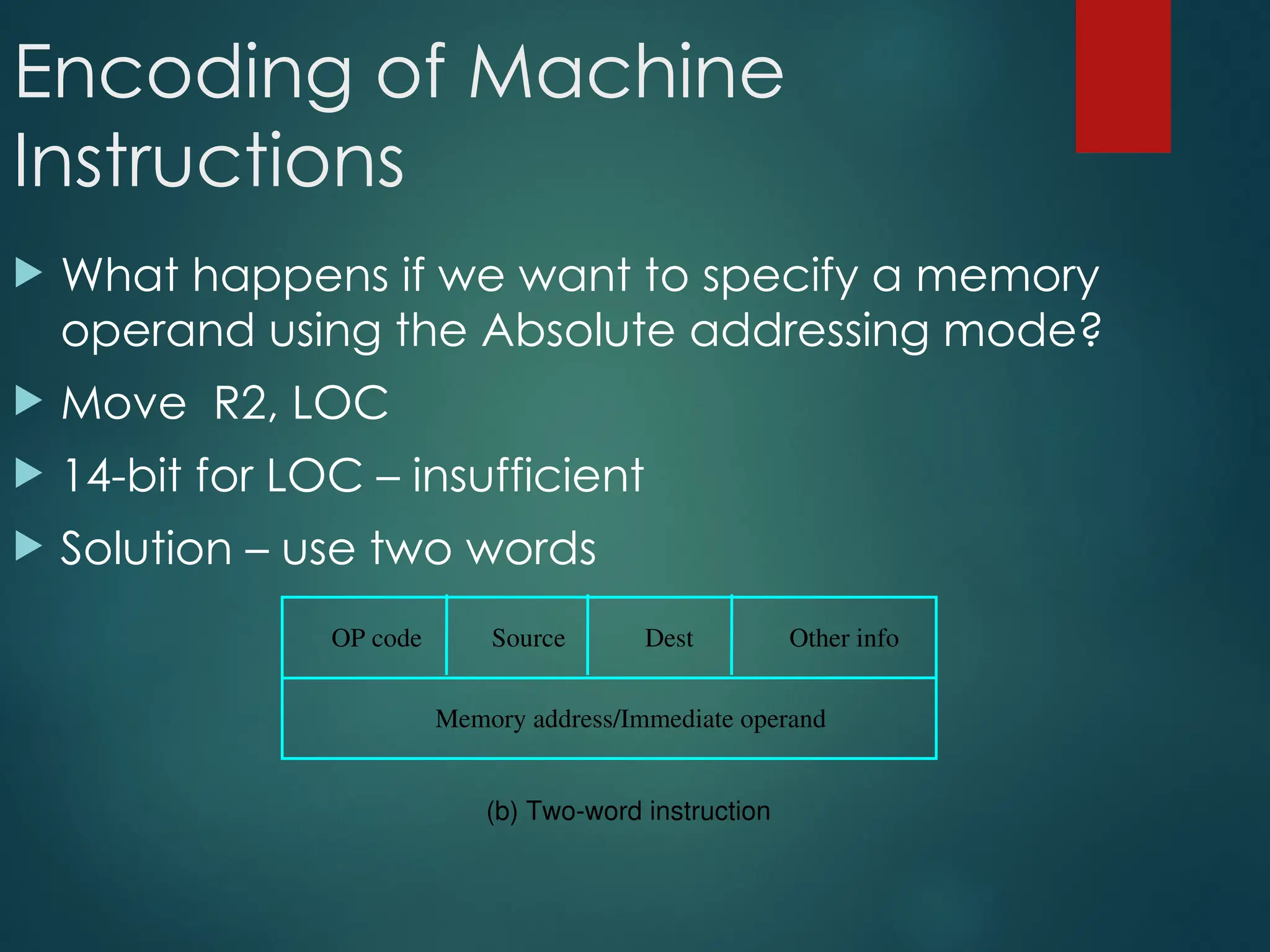
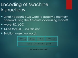
What happens if we want to specify a memory
operand using the Absolute addressing mode?
Move R2, LOC
14-bit for LOC – insufficient
Solution – use two words
(b) Two-word instruction
Memory address/Immediate operand
OP code Source Dest Other info
123.
Encoding of Machine
Instructions
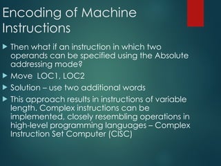
Then what if an instruction in which two
operands can be specified using the Absolute
addressing mode?
Move LOC1, LOC2
Solution – use two additional words
This approach results in instructions of variable
length. Complex instructions can be
implemented, closely resembling operations in
high-level programming languages – Complex
Instruction Set Computer (CISC)
124.
Encoding of Machine
Instructions
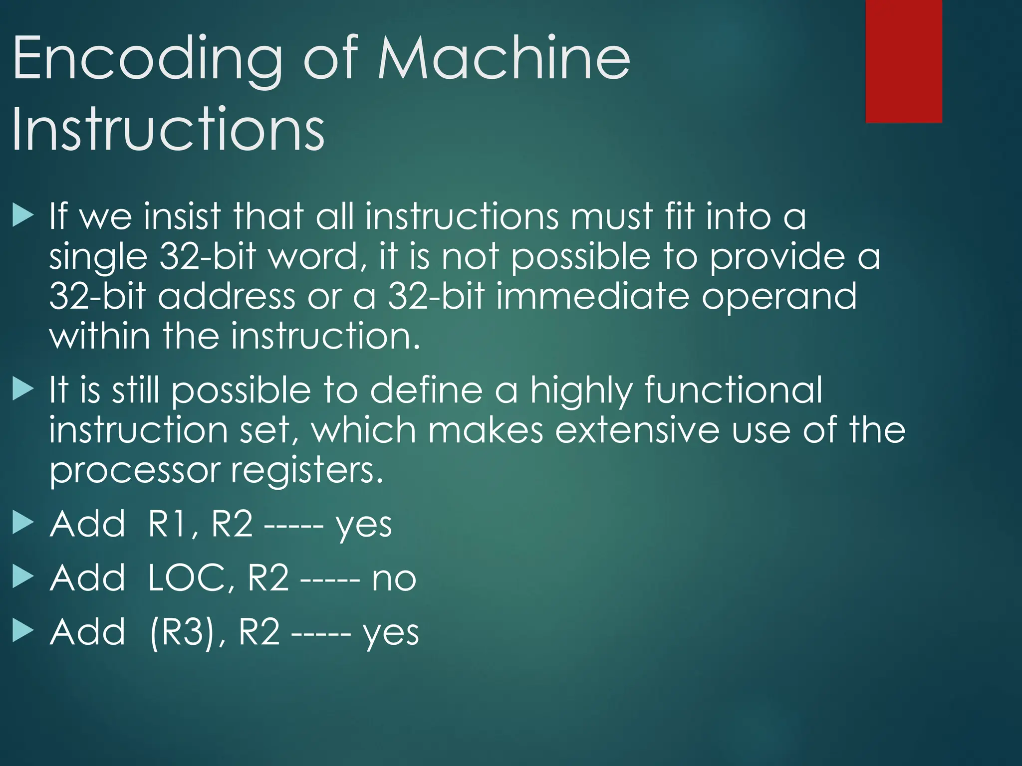
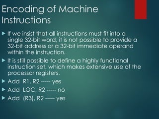
If we insist that all instructions must fit into a
single 32-bit word, it is not possible to provide a
32-bit address or a 32-bit immediate operand
within the instruction.
It is still possible to define a highly functional
instruction set, which makes extensive use of the
processor registers.
Add R1, R2 ----- yes
Add LOC, R2 ----- no
Add (R3), R2 ----- yes


![Five Execution Steps
Step name
Step name Action for R-type
Action for R-type
instructions
instructions
Action for Memory-
Action for Memory-
reference Instructions
reference Instructions
Action for
Action for
branches
branches
Action for
Action for
jumps
jumps
Instruction fetch IR = MEM[PC]
PC = PC + 4
Instruction decode/ register
fetch
A = Reg[IR[25-21]]
B = Reg[IR[20-16]]
ALUOut = PC + (sign extend (IR[15-0])<<2)
Execution, address
computation, branch/jump
completion
ALUOut = A op B ALUOut = A+sign
extend(IR[15-0])
IF(A==B) Then
PC=ALUOut
PC=PC[31-
28]||(IR[25-
0]<<2)
Memory access or R-type
completion
Reg[IR[15-11]] =
ALUOut
Load:MDR =Mem[ALUOut]
or
Store:Mem[ALUOut] = B
Memory read completion Load: Reg[IR[20-16]] =
MDR](https://image.slidesharecdn.com/basicstructureofcomputers-250930072919-cb970ef0/85/Basic-Structure-of-Computers-Basic-of-Comp-ppt-14-320.jpg)


![Register Transfer Notation
Identify a location by a symbolic name standing for its
hardware binary address (LOC, R0,…)
Contents of a location are denoted by placing square
brackets around the name of the location (R1←[LOC], R3
←[R1]+[R2])
Register Transfer Notation (RTN)](https://image.slidesharecdn.com/basicstructureofcomputers-250930072919-cb970ef0/85/Basic-Structure-of-Computers-Basic-of-Comp-ppt-64-320.jpg)
![Assembly Language
Notation
Represent machine instructions and programs.
Move LOC, R1 = R1←[LOC]
Add R1, R2, R3 = R3 ←[R1]+[R2]](https://image.slidesharecdn.com/basicstructureofcomputers-250930072919-cb970ef0/85/Basic-Structure-of-Computers-Basic-of-Comp-ppt-65-320.jpg)
![Instruction Formats
Three-Address Instructions
ADD R1, R2, R3 R1 ← R2 + R3
Two-Address Instructions
ADD R1, R2 R1 ← R1 + R2
One-Address Instructions
ADD M AC ← AC + M[AR]
Zero-Address Instructions
ADD TOS ← TOS + (TOS – 1)
RISC Instructions
Lots of registers. Memory is restricted to Load & Store
Opcode Operand(s) or Address(es)](https://image.slidesharecdn.com/basicstructureofcomputers-250930072919-cb970ef0/85/Basic-Structure-of-Computers-Basic-of-Comp-ppt-67-320.jpg)
![Instruction Formats
Example: Evaluate (A+B) (C+D)
Three-Address
1. ADD R1, A, B ; R1 ← M[A] +
M[B]
2. ADD R2, C, D ; R2 ← M[C] +
M[D]
3. MUL X, R1, R2 ; M[X] ← R1 R2](https://image.slidesharecdn.com/basicstructureofcomputers-250930072919-cb970ef0/85/Basic-Structure-of-Computers-Basic-of-Comp-ppt-68-320.jpg)
![Instruction Formats
Example: Evaluate (A+B) (C+D)
Two-Address
1. MOV R1, A ; R1 ← M[A]
2. ADD R1, B ; R1 ← R1 + M[B]
3. MOV R2, C ; R2 ← M[C]
4. ADD R2, D ; R2 ← R2 + M[D]
5. MUL R1, R2 ; R1 ← R1 R2
6. MOV X, R1 ; M[X] ← R1](https://image.slidesharecdn.com/basicstructureofcomputers-250930072919-cb970ef0/85/Basic-Structure-of-Computers-Basic-of-Comp-ppt-69-320.jpg)
![Instruction Formats
Example: Evaluate (A+B) (C+D)
One-Address
1. LOAD A ; AC ← M[A]
2. ADD B ; AC ← AC + M[B]
3. STORE T ; M[T] ← AC
4. LOAD C ; AC ← M[C]
5. ADD D ; AC ← AC + M[D]
6. MUL T ; AC ← AC M[T]
7. STORE X ; M[X] ← AC](https://image.slidesharecdn.com/basicstructureofcomputers-250930072919-cb970ef0/85/Basic-Structure-of-Computers-Basic-of-Comp-ppt-70-320.jpg)
![Instruction Formats
Example: Evaluate (A+B) (C+D)
Zero-Address
1. PUSH A ; TOS ← A
2. PUSH B ; TOS ← B
3. ADD ; TOS ← (A + B)
4. PUSH C ; TOS ← C
5. PUSH D ; TOS ← D
6. ADD ; TOS ← (C + D)
7. MUL ; TOS ←
(C+D)(A+B)
8. POP X ; M[X] ← TOS](https://image.slidesharecdn.com/basicstructureofcomputers-250930072919-cb970ef0/85/Basic-Structure-of-Computers-Basic-of-Comp-ppt-71-320.jpg)
![Instruction Formats
Example: Evaluate (A+B) (C+D)
RISC
1. LOAD R1, A ; R1 ← M[A]
2. LOAD R2, B ; R2 ← M[B]
3. LOAD R3, C ; R3 ← M[C]
4. LOAD R4, D ; R4 ← M[D]
5. ADD R1, R1, R2 ; R1 ← R1 + R2
6. ADD R3, R3, R4 ; R3 ← R3 + R4
7. MUL R1, R1, R3 ; R1 ← R1 R3
8. STORE X, R1 ; M[X] ← R1](https://image.slidesharecdn.com/basicstructureofcomputers-250930072919-cb970ef0/85/Basic-Structure-of-Computers-Basic-of-Comp-ppt-72-320.jpg)


![Addressing Modes
Implied
AC is implied in “ADD M[AR]” in “One-Address” instr.
TOS is implied in “ADD” in “Zero-Address” instr.
Immediate
The use of a constant in “MOV R1, 5”, i.e. R1 ← 5
Register
Indicate which register holds the operand
Opcode Mode ...](https://image.slidesharecdn.com/basicstructureofcomputers-250930072919-cb970ef0/85/Basic-Structure-of-Computers-Basic-of-Comp-ppt-82-320.jpg)


![Addressing Modes
The different
ways in
which the
location of
an operand
is specified
in an
instruction
are referred
to as
addressing
modes.
Name Assembler syntax Addressingfunction
Immediate #Value Operand= Value
Register Ri EA = Ri
Absolute(Direct) LOC EA = LOC
Indirect (Ri ) EA = [Ri]
(LOC) EA = [LOC]
Index X(R i) EA = [Ri] + X
Basewith index (Ri ,Rj ) EA = [Ri] + [Rj]
Basewith index X(R i,Rj ) EA = [Ri] + [Rj] + X
andoffset
Relative X(PC) EA = [PC] + X
Autoincremen
t (Ri )+ EA = [Ri] ;
Incremen
t Ri
Autodecrement (Ri ) Decremen
t Ri ;
EA = [Ri]
](https://image.slidesharecdn.com/basicstructureofcomputers-250930072919-cb970ef0/85/Basic-Structure-of-Computers-Basic-of-Comp-ppt-88-320.jpg)
![Indexing and Arrays
Index mode – the effective address of the
operand is generated by adding a constant
value to the contents of a register.
Index register
X(Ri): EA = X + [Ri]
The constant X may be given either as an
explicit number or as a symbolic name
representing a numerical value.
If X is shorter than a word, sign-extension is
needed.](https://image.slidesharecdn.com/basicstructureofcomputers-250930072919-cb970ef0/85/Basic-Structure-of-Computers-Basic-of-Comp-ppt-89-320.jpg)
![Indexing and Arrays
In general, the Index mode facilitates access to an operand
whose location is defined relative to a reference point within
the data structure in which the operand appears.
Several variations:
(Ri, Rj): EA = [Ri] + [Rj]
X(Ri, Rj): EA = X + [Ri] + [Rj]](https://image.slidesharecdn.com/basicstructureofcomputers-250930072919-cb970ef0/85/Basic-Structure-of-Computers-Basic-of-Comp-ppt-90-320.jpg)

![Data Transfer Instructions
Mode Assembly Register Transfer
Direct address LD ADR AC ← M[ADR]
Indirect address LD @ADR AC ← M[M[ADR]]
Relative address LD $ADR AC ← M[PC+ADR]
Immediate operand LD #NBR AC ← NBR
Index addressing LD ADR(X) AC ← M[ADR+XR]
Register LD R1 AC ← R1
Register indirect LD (R1) AC ← M[R1]
Autoincrement LD (R1)+ AC ← M[R1], R1 ← R1+1](https://image.slidesharecdn.com/basicstructureofcomputers-250930072919-cb970ef0/85/Basic-Structure-of-Computers-Basic-of-Comp-ppt-95-320.jpg)


![Stack Organization
PUSH
SP ← SP – 1
M[SP] ← DR
If (SP = 0) then (FULL ← 1)
EMPTY ← 0
SP
Stack Bottom
Current
Top of Stack
TOS 0
1
2
3
4
7
8
9
10
5
6
Stack
0 0 5 5
0 0 0 8
0 0 2 5
0 0 1 5
0 1 2 3
FULL EMPTY
1 6 9 0
1 6 9 0
Current
Top of Stack
TOS](https://image.slidesharecdn.com/basicstructureofcomputers-250930072919-cb970ef0/85/Basic-Structure-of-Computers-Basic-of-Comp-ppt-109-320.jpg)
![Stack Organization
POP
DR ← M[SP]
SP ← SP + 1
If (SP = 11) then (EMPTY ← 1)
FULL ← 0
SP
Stack Bottom
Current
Top of Stack
TOS 0
1
2
3
4
7
8
9
10
5
6
Stack
0 0 5 5
0 0 0 8
0 0 2 5
0 0 1 5
0 1 2 3
FULL EMPTY
1 6 9 0
1 6 9 0
Current
Top of Stack
TOS](https://image.slidesharecdn.com/basicstructureofcomputers-250930072919-cb970ef0/85/Basic-Structure-of-Computers-Basic-of-Comp-ppt-110-320.jpg)
![0
1
2
102
202
201
200
100
101
Stack Organization
Memory Stack
PUSH
SP ← SP – 1
M[SP] ← DR
POP
DR ← M[SP]
SP ← SP + 1
PC
AR
SP](https://image.slidesharecdn.com/basicstructureofcomputers-250930072919-cb970ef0/85/Basic-Structure-of-Computers-Basic-of-Comp-ppt-111-320.jpg)

![Reverse Polish Notation
Example
(A + B) [C (D + E) + F]
(A B +) (D E +) C
F +](https://image.slidesharecdn.com/basicstructureofcomputers-250930072919-cb970ef0/85/Basic-Structure-of-Computers-Basic-of-Comp-ppt-113-320.jpg)


![Multiplication and Division
Not very popular (especially division)
Multiply Ri, Rj
Rj ← [Ri] х [Rj]
2n-bit product case: high-order half in R(j+1)
Divide Ri, Rj
Rj ← [Ri] / [Rj]
Quotient is in Rj, remainder may be placed in R(j+1)](https://image.slidesharecdn.com/basicstructureofcomputers-250930072919-cb970ef0/85/Basic-Structure-of-Computers-Basic-of-Comp-ppt-119-320.jpg)


![Five Execution Steps
Step name
Step name Action for R-type
Action for R-type
instructions
instructions
Action for Memory-
Action for Memory-
reference Instructions
reference Instructions
Action for
Action for
branches
branches
Action for
Action for
jumps
jumps
Instruction fetch IR = MEM[PC]
PC = PC + 4
Instruction decode/ register
fetch
A = Reg[IR[25-21]]
B = Reg[IR[20-16]]
ALUOut = PC + (sign extend (IR[15-0])<<2)
Execution, address
computation, branch/jump
completion
ALUOut = A op B ALUOut = A+sign
extend(IR[15-0])
IF(A==B) Then
PC=ALUOut
PC=PC[31-
28]||(IR[25-
0]<<2)
Memory access or R-type
completion
Reg[IR[15-11]] =
ALUOut
Load:MDR =Mem[ALUOut]
or
Store:Mem[ALUOut] = B
Memory read completion Load: Reg[IR[20-16]] =
MDR](https://image.slidesharecdn.com/basicstructureofcomputers-250930072919-cb970ef0/75/Basic-Structure-of-Computers-Basic-of-Comp-ppt-14-2048.jpg)


![Register Transfer Notation
Identify a location by a symbolic name standing for its
hardware binary address (LOC, R0,…)
Contents of a location are denoted by placing square
brackets around the name of the location (R1←[LOC], R3
←[R1]+[R2])
Register Transfer Notation (RTN)](https://image.slidesharecdn.com/basicstructureofcomputers-250930072919-cb970ef0/75/Basic-Structure-of-Computers-Basic-of-Comp-ppt-64-2048.jpg)
![Assembly Language
Notation
Represent machine instructions and programs.
Move LOC, R1 = R1←[LOC]
Add R1, R2, R3 = R3 ←[R1]+[R2]](https://image.slidesharecdn.com/basicstructureofcomputers-250930072919-cb970ef0/75/Basic-Structure-of-Computers-Basic-of-Comp-ppt-65-2048.jpg)
![Instruction Formats
Three-Address Instructions
ADD R1, R2, R3 R1 ← R2 + R3
Two-Address Instructions
ADD R1, R2 R1 ← R1 + R2
One-Address Instructions
ADD M AC ← AC + M[AR]
Zero-Address Instructions
ADD TOS ← TOS + (TOS – 1)
RISC Instructions
Lots of registers. Memory is restricted to Load & Store
Opcode Operand(s) or Address(es)](https://image.slidesharecdn.com/basicstructureofcomputers-250930072919-cb970ef0/75/Basic-Structure-of-Computers-Basic-of-Comp-ppt-67-2048.jpg)
![Instruction Formats
Example: Evaluate (A+B) (C+D)
Three-Address
1. ADD R1, A, B ; R1 ← M[A] +
M[B]
2. ADD R2, C, D ; R2 ← M[C] +
M[D]
3. MUL X, R1, R2 ; M[X] ← R1 R2](https://image.slidesharecdn.com/basicstructureofcomputers-250930072919-cb970ef0/75/Basic-Structure-of-Computers-Basic-of-Comp-ppt-68-2048.jpg)
![Instruction Formats
Example: Evaluate (A+B) (C+D)
Two-Address
1. MOV R1, A ; R1 ← M[A]
2. ADD R1, B ; R1 ← R1 + M[B]
3. MOV R2, C ; R2 ← M[C]
4. ADD R2, D ; R2 ← R2 + M[D]
5. MUL R1, R2 ; R1 ← R1 R2
6. MOV X, R1 ; M[X] ← R1](https://image.slidesharecdn.com/basicstructureofcomputers-250930072919-cb970ef0/75/Basic-Structure-of-Computers-Basic-of-Comp-ppt-69-2048.jpg)
![Instruction Formats
Example: Evaluate (A+B) (C+D)
One-Address
1. LOAD A ; AC ← M[A]
2. ADD B ; AC ← AC + M[B]
3. STORE T ; M[T] ← AC
4. LOAD C ; AC ← M[C]
5. ADD D ; AC ← AC + M[D]
6. MUL T ; AC ← AC M[T]
7. STORE X ; M[X] ← AC](https://image.slidesharecdn.com/basicstructureofcomputers-250930072919-cb970ef0/75/Basic-Structure-of-Computers-Basic-of-Comp-ppt-70-2048.jpg)
![Instruction Formats
Example: Evaluate (A+B) (C+D)
Zero-Address
1. PUSH A ; TOS ← A
2. PUSH B ; TOS ← B
3. ADD ; TOS ← (A + B)
4. PUSH C ; TOS ← C
5. PUSH D ; TOS ← D
6. ADD ; TOS ← (C + D)
7. MUL ; TOS ←
(C+D)(A+B)
8. POP X ; M[X] ← TOS](https://image.slidesharecdn.com/basicstructureofcomputers-250930072919-cb970ef0/75/Basic-Structure-of-Computers-Basic-of-Comp-ppt-71-2048.jpg)
![Instruction Formats
Example: Evaluate (A+B) (C+D)
RISC
1. LOAD R1, A ; R1 ← M[A]
2. LOAD R2, B ; R2 ← M[B]
3. LOAD R3, C ; R3 ← M[C]
4. LOAD R4, D ; R4 ← M[D]
5. ADD R1, R1, R2 ; R1 ← R1 + R2
6. ADD R3, R3, R4 ; R3 ← R3 + R4
7. MUL R1, R1, R3 ; R1 ← R1 R3
8. STORE X, R1 ; M[X] ← R1](https://image.slidesharecdn.com/basicstructureofcomputers-250930072919-cb970ef0/75/Basic-Structure-of-Computers-Basic-of-Comp-ppt-72-2048.jpg)

![Addressing Modes
Implied
AC is implied in “ADD M[AR]” in “One-Address” instr.
TOS is implied in “ADD” in “Zero-Address” instr.
Immediate
The use of a constant in “MOV R1, 5”, i.e. R1 ← 5
Register
Indicate which register holds the operand
Opcode Mode ...](https://image.slidesharecdn.com/basicstructureofcomputers-250930072919-cb970ef0/75/Basic-Structure-of-Computers-Basic-of-Comp-ppt-82-2048.jpg)

![Addressing Modes
The different
ways in
which the
location of
an operand
is specified
in an
instruction
are referred
to as
addressing
modes.
Name Assembler syntax Addressingfunction
Immediate #Value Operand= Value
Register Ri EA = Ri
Absolute(Direct) LOC EA = LOC
Indirect (Ri ) EA = [Ri]
(LOC) EA = [LOC]
Index X(R i) EA = [Ri] + X
Basewith index (Ri ,Rj ) EA = [Ri] + [Rj]
Basewith index X(R i,Rj ) EA = [Ri] + [Rj] + X
andoffset
Relative X(PC) EA = [PC] + X
Autoincremen
t (Ri )+ EA = [Ri] ;
Incremen
t Ri
Autodecrement (Ri ) Decremen
t Ri ;
EA = [Ri]
](https://image.slidesharecdn.com/basicstructureofcomputers-250930072919-cb970ef0/75/Basic-Structure-of-Computers-Basic-of-Comp-ppt-88-2048.jpg)
![Indexing and Arrays
Index mode – the effective address of the
operand is generated by adding a constant
value to the contents of a register.
Index register
X(Ri): EA = X + [Ri]
The constant X may be given either as an
explicit number or as a symbolic name
representing a numerical value.
If X is shorter than a word, sign-extension is
needed.](https://image.slidesharecdn.com/basicstructureofcomputers-250930072919-cb970ef0/75/Basic-Structure-of-Computers-Basic-of-Comp-ppt-89-2048.jpg)
![Indexing and Arrays
In general, the Index mode facilitates access to an operand
whose location is defined relative to a reference point within
the data structure in which the operand appears.
Several variations:
(Ri, Rj): EA = [Ri] + [Rj]
X(Ri, Rj): EA = X + [Ri] + [Rj]](https://image.slidesharecdn.com/basicstructureofcomputers-250930072919-cb970ef0/75/Basic-Structure-of-Computers-Basic-of-Comp-ppt-90-2048.jpg)

![Data Transfer Instructions
Mode Assembly Register Transfer
Direct address LD ADR AC ← M[ADR]
Indirect address LD @ADR AC ← M[M[ADR]]
Relative address LD $ADR AC ← M[PC+ADR]
Immediate operand LD #NBR AC ← NBR
Index addressing LD ADR(X) AC ← M[ADR+XR]
Register LD R1 AC ← R1
Register indirect LD (R1) AC ← M[R1]
Autoincrement LD (R1)+ AC ← M[R1], R1 ← R1+1](https://image.slidesharecdn.com/basicstructureofcomputers-250930072919-cb970ef0/75/Basic-Structure-of-Computers-Basic-of-Comp-ppt-95-2048.jpg)


![Stack Organization
PUSH
SP ← SP – 1
M[SP] ← DR
If (SP = 0) then (FULL ← 1)
EMPTY ← 0
SP
Stack Bottom
Current
Top of Stack
TOS 0
1
2
3
4
7
8
9
10
5
6
Stack
0 0 5 5
0 0 0 8
0 0 2 5
0 0 1 5
0 1 2 3
FULL EMPTY
1 6 9 0
1 6 9 0
Current
Top of Stack
TOS](https://image.slidesharecdn.com/basicstructureofcomputers-250930072919-cb970ef0/75/Basic-Structure-of-Computers-Basic-of-Comp-ppt-109-2048.jpg)
![Stack Organization
POP
DR ← M[SP]
SP ← SP + 1
If (SP = 11) then (EMPTY ← 1)
FULL ← 0
SP
Stack Bottom
Current
Top of Stack
TOS 0
1
2
3
4
7
8
9
10
5
6
Stack
0 0 5 5
0 0 0 8
0 0 2 5
0 0 1 5
0 1 2 3
FULL EMPTY
1 6 9 0
1 6 9 0
Current
Top of Stack
TOS](https://image.slidesharecdn.com/basicstructureofcomputers-250930072919-cb970ef0/75/Basic-Structure-of-Computers-Basic-of-Comp-ppt-110-2048.jpg)
![0
1
2
102
202
201
200
100
101
Stack Organization
Memory Stack
PUSH
SP ← SP – 1
M[SP] ← DR
POP
DR ← M[SP]
SP ← SP + 1
PC
AR
SP](https://image.slidesharecdn.com/basicstructureofcomputers-250930072919-cb970ef0/75/Basic-Structure-of-Computers-Basic-of-Comp-ppt-111-2048.jpg)
![Reverse Polish Notation
Example
(A + B) [C (D + E) + F]
(A B +) (D E +) C
F +](https://image.slidesharecdn.com/basicstructureofcomputers-250930072919-cb970ef0/75/Basic-Structure-of-Computers-Basic-of-Comp-ppt-113-2048.jpg)

![Multiplication and Division
Not very popular (especially division)
Multiply Ri, Rj
Rj ← [Ri] х [Rj]
2n-bit product case: high-order half in R(j+1)
Divide Ri, Rj
Rj ← [Ri] / [Rj]
Quotient is in Rj, remainder may be placed in R(j+1)](https://image.slidesharecdn.com/basicstructureofcomputers-250930072919-cb970ef0/75/Basic-Structure-of-Computers-Basic-of-Comp-ppt-119-2048.jpg)