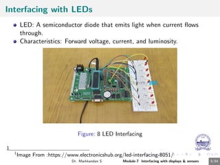
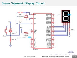
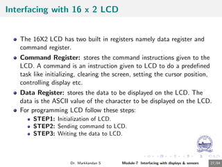
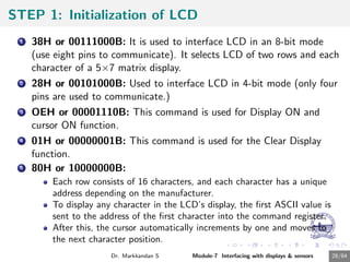
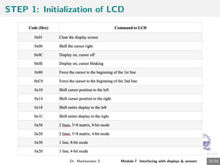
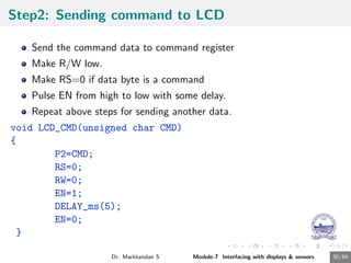
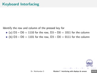
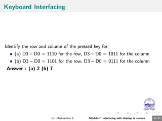
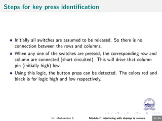
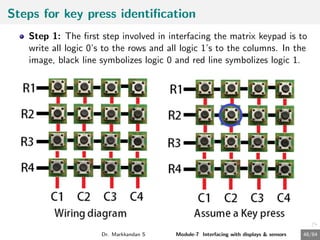
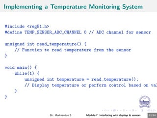
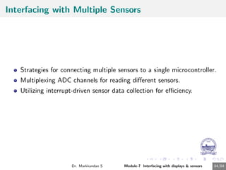
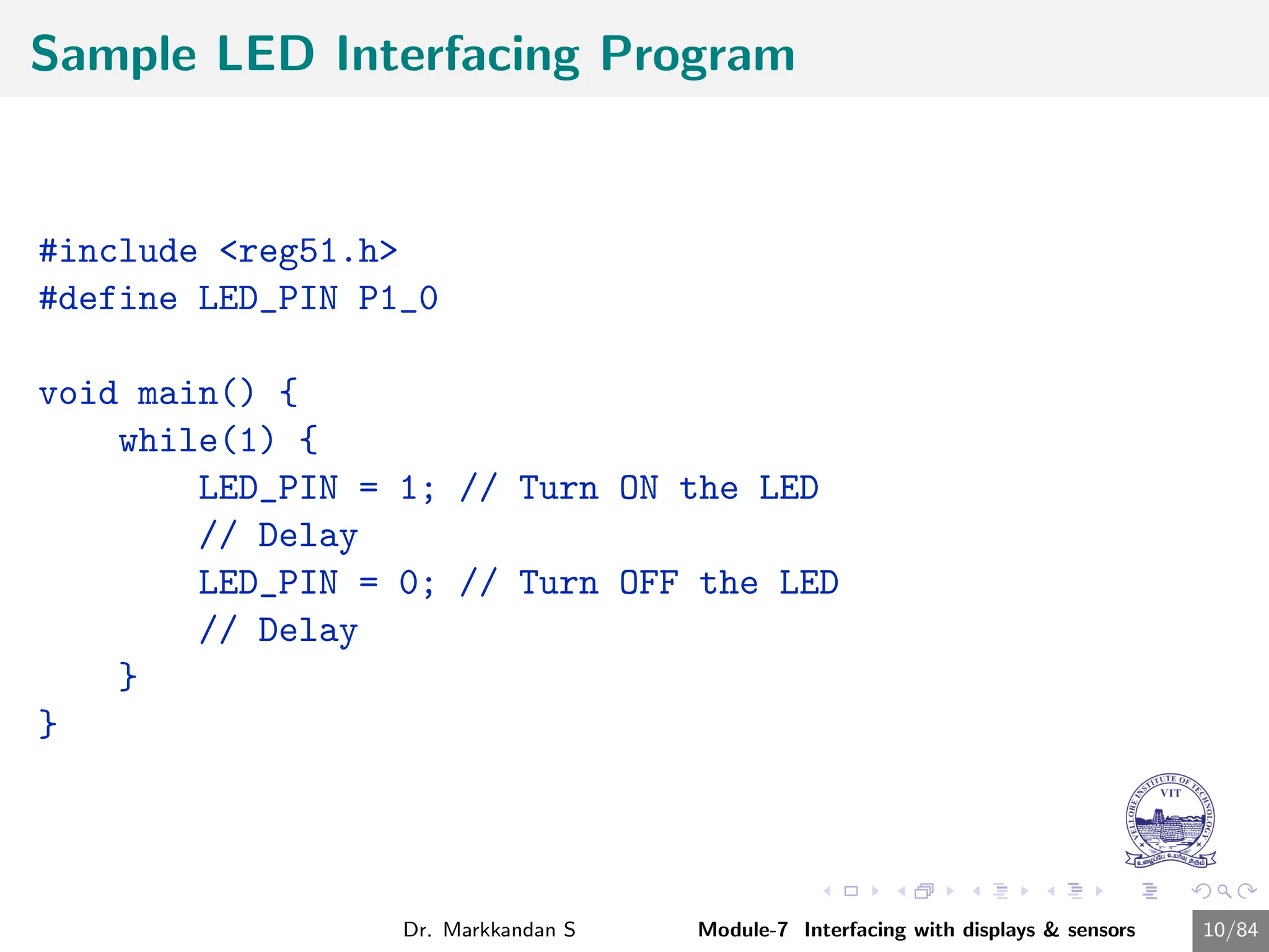
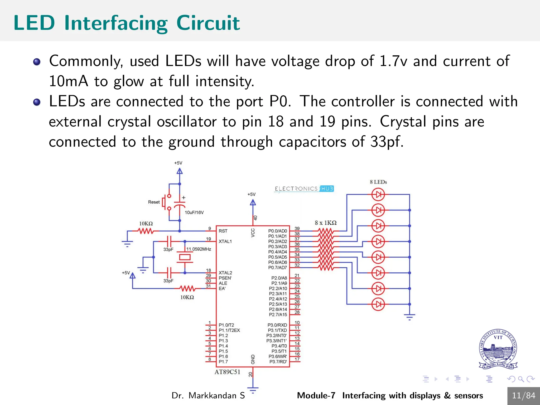
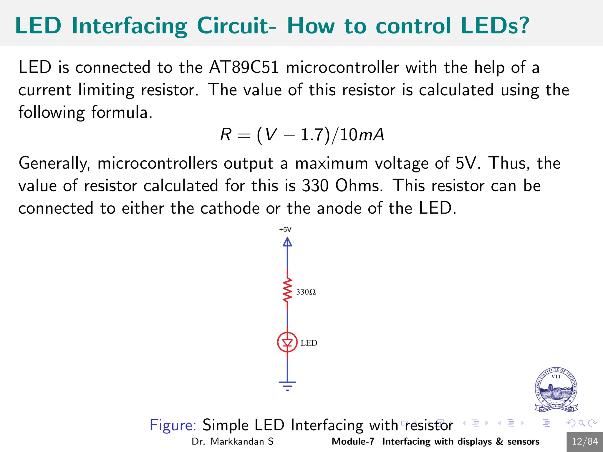
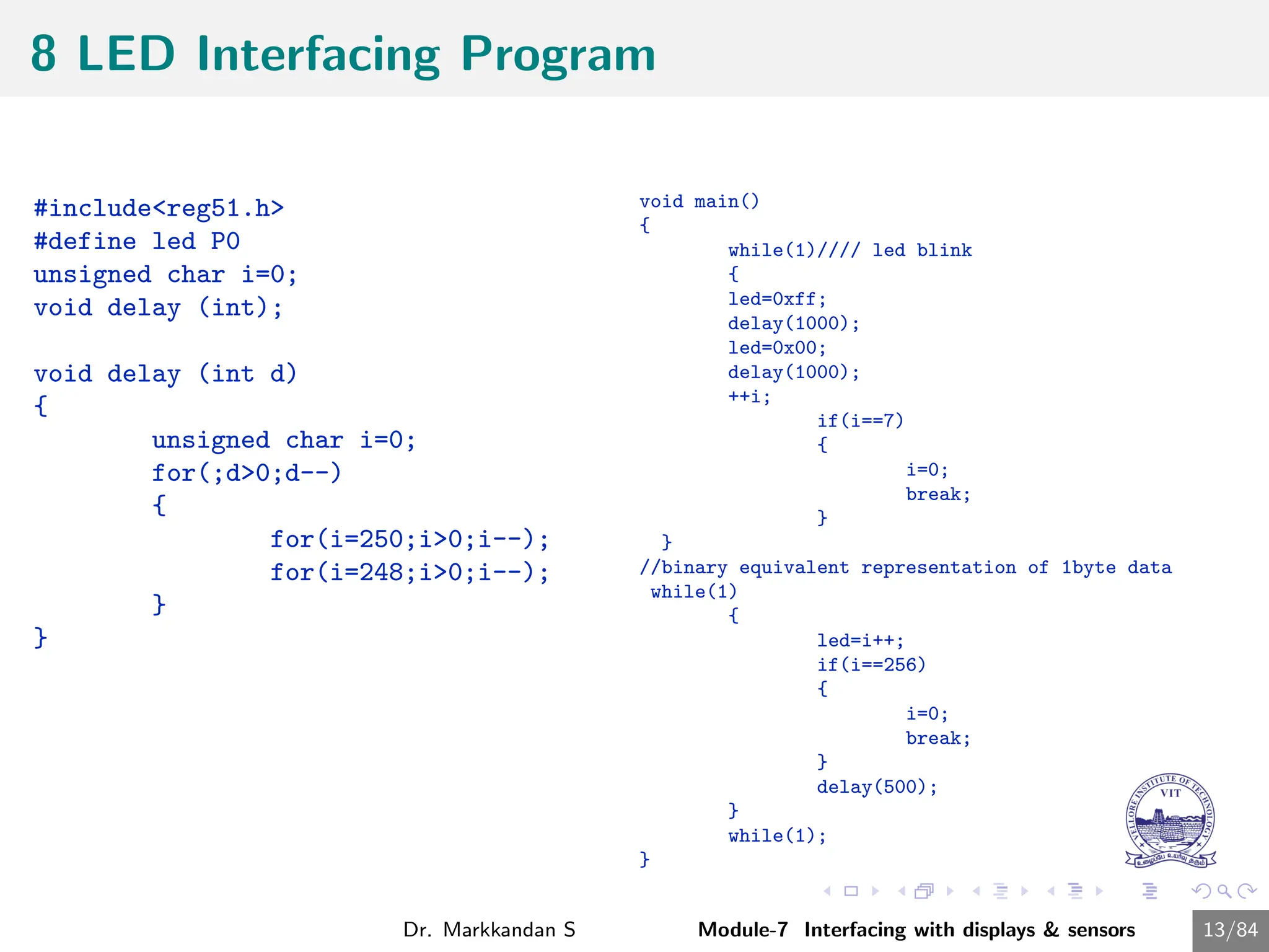
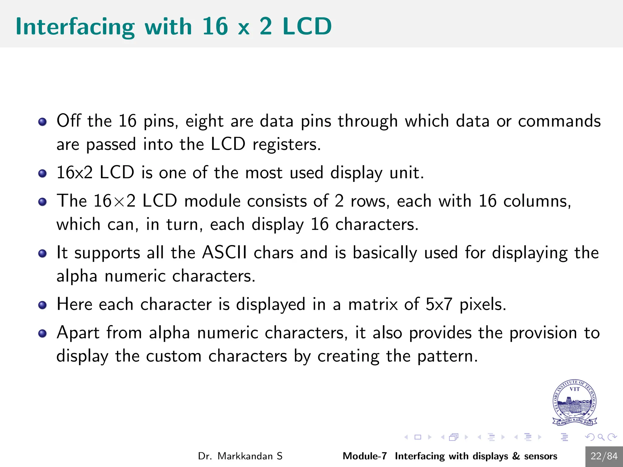
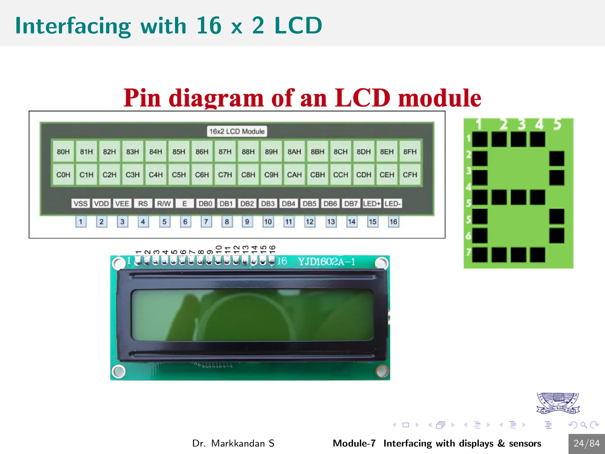
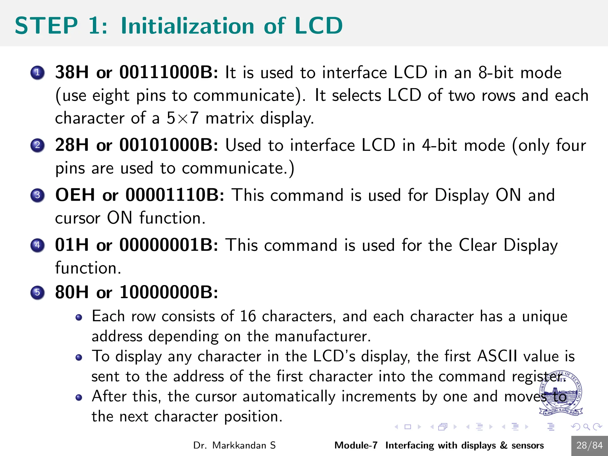
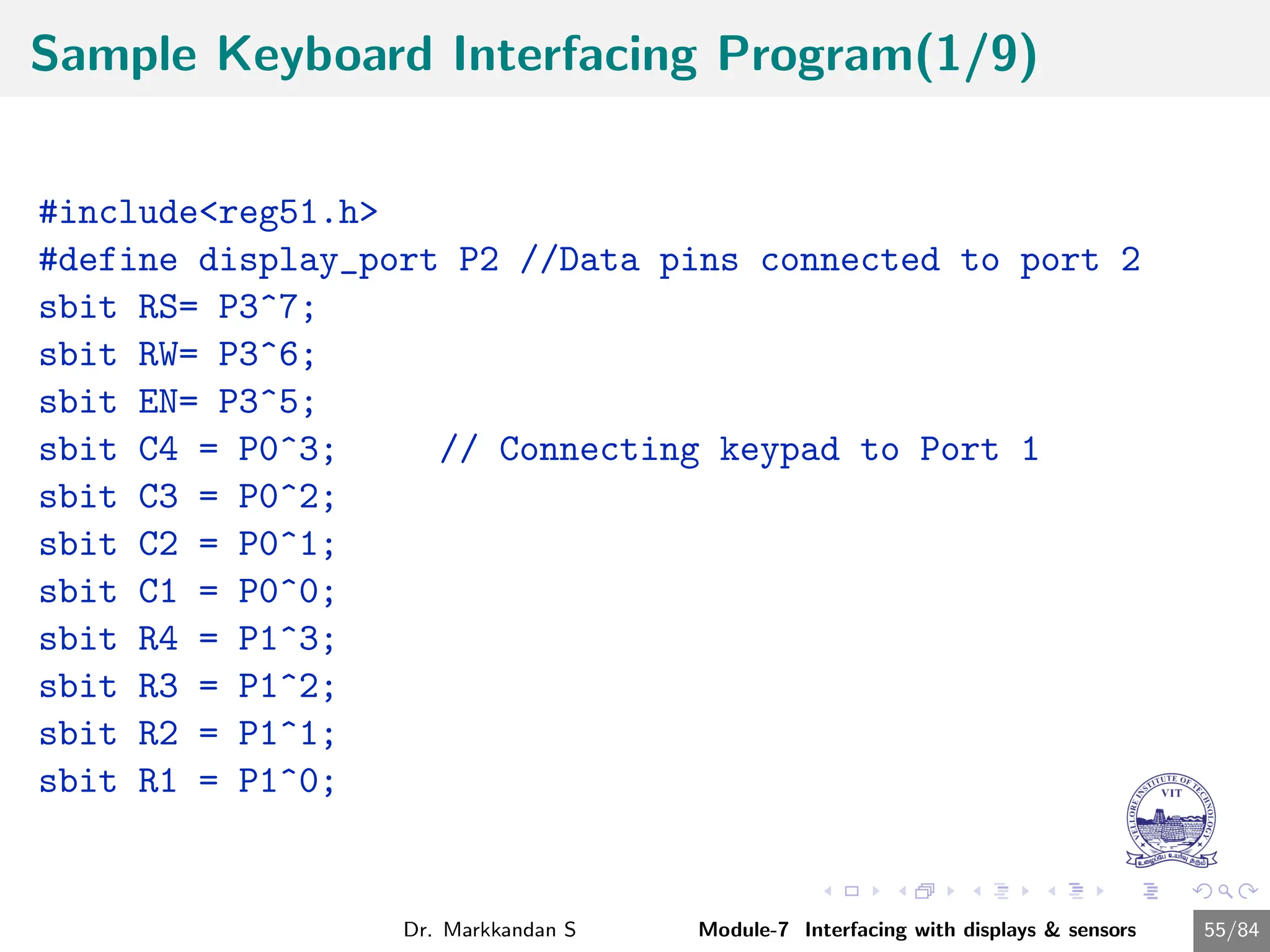
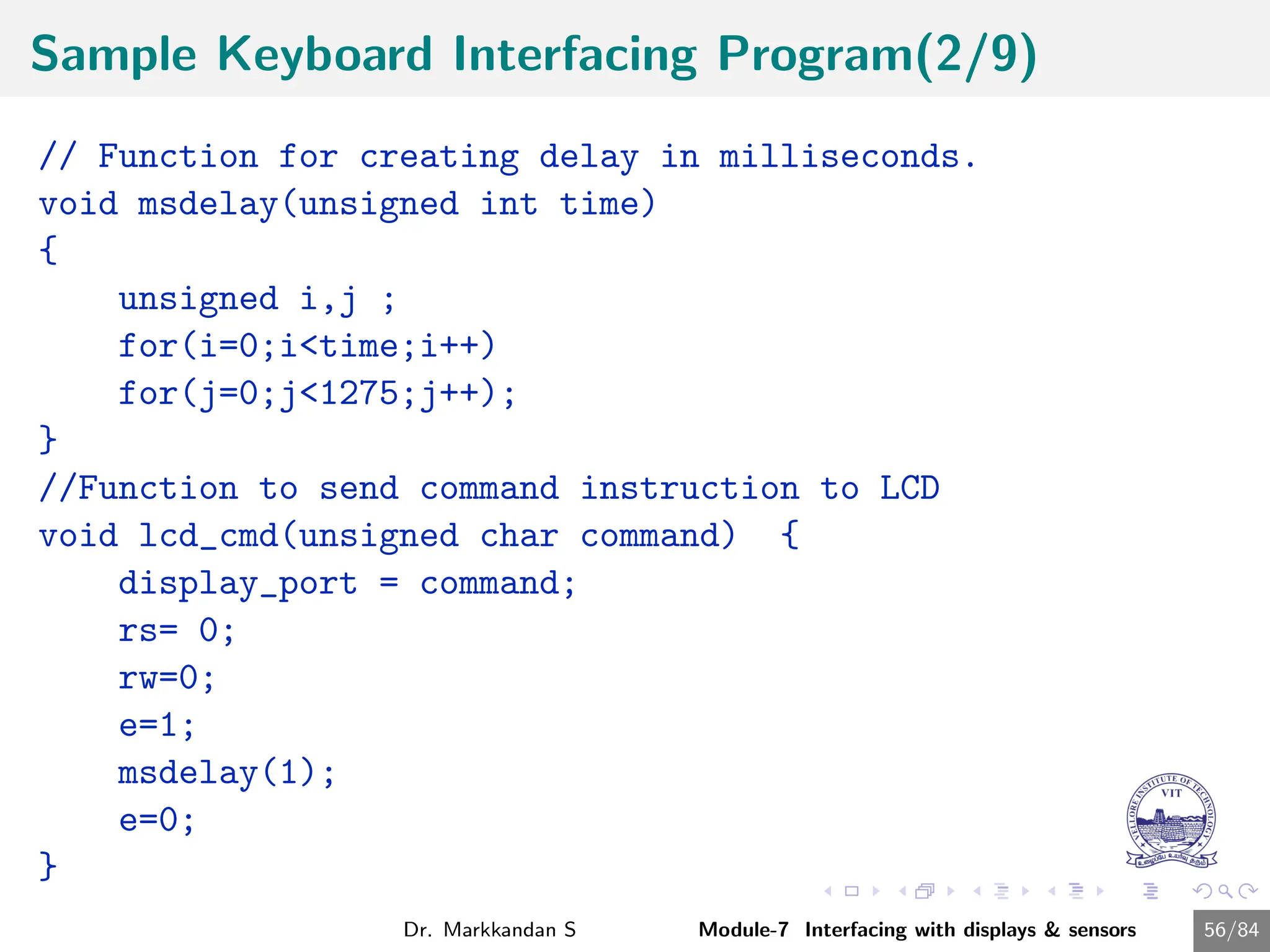
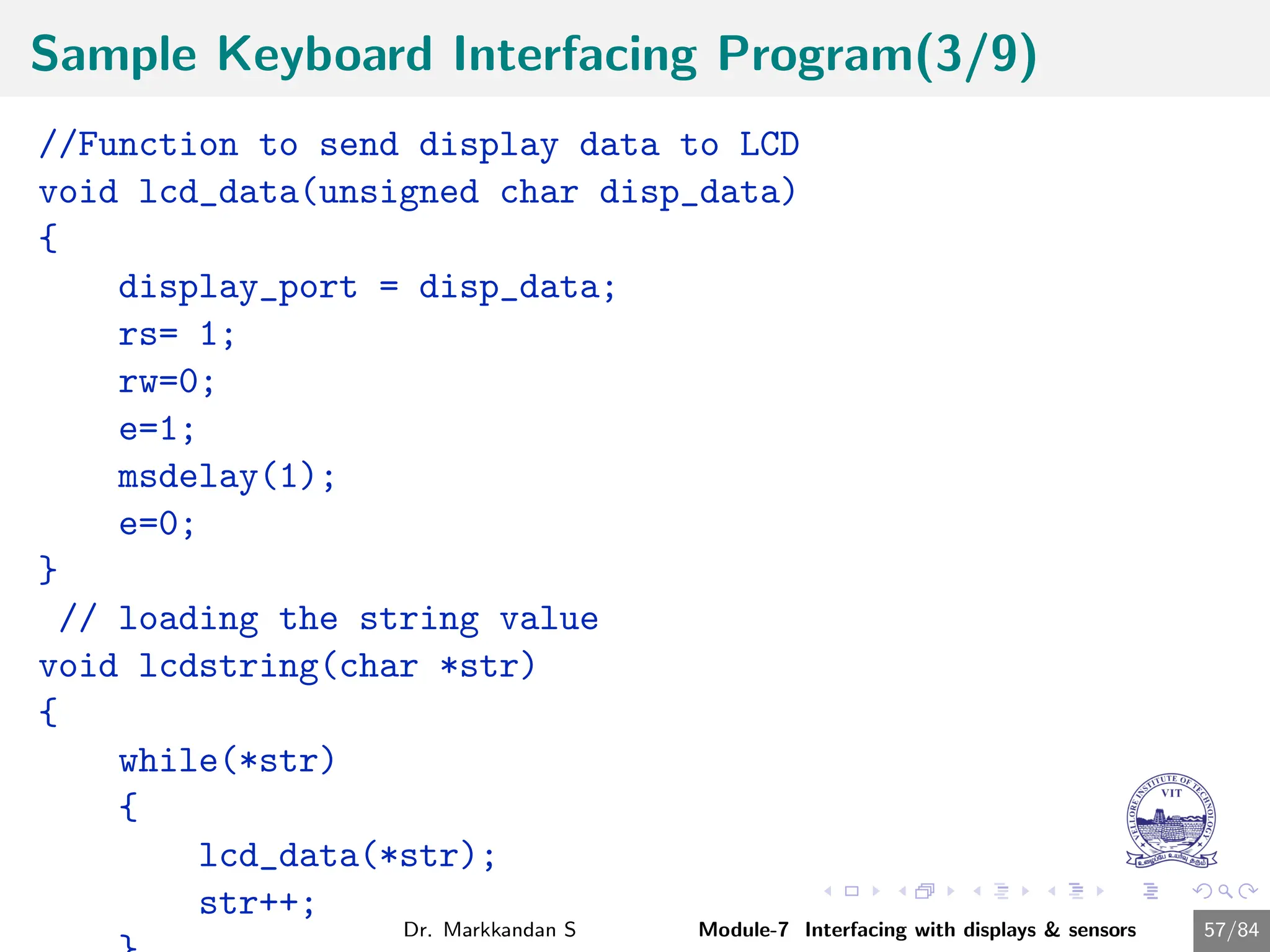
The document provides a comprehensive overview of interfacing displays and sensors in embedded systems, detailing topics such as LED, seven-segment display, and LCD interfacing. It covers the definition, importance, and basic concepts of interfacing, including signal levels and control techniques. Additionally, it includes sample codes and descriptions for interfacing various components, emphasizing the operational modes and commands for LCDs.


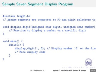
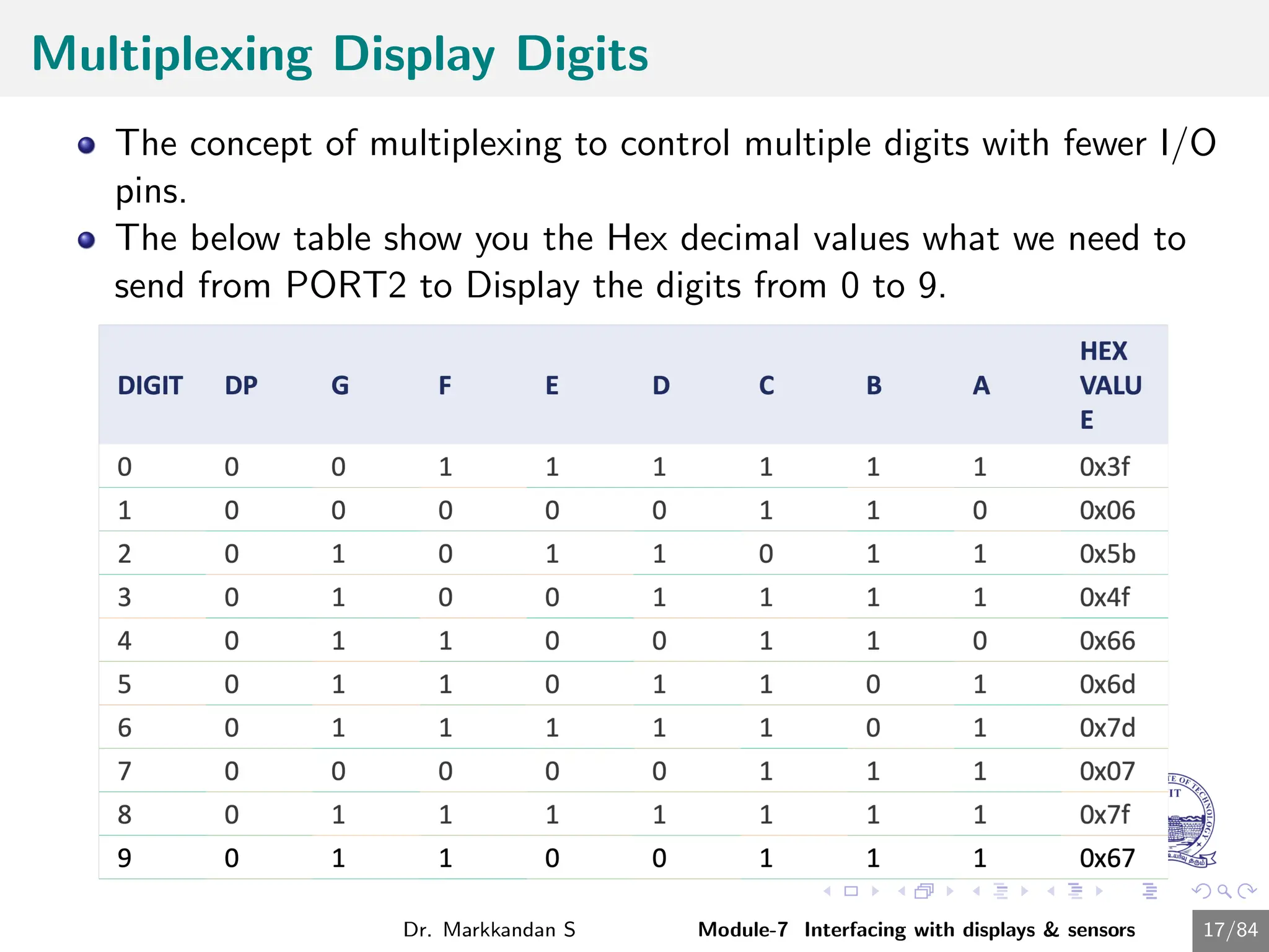
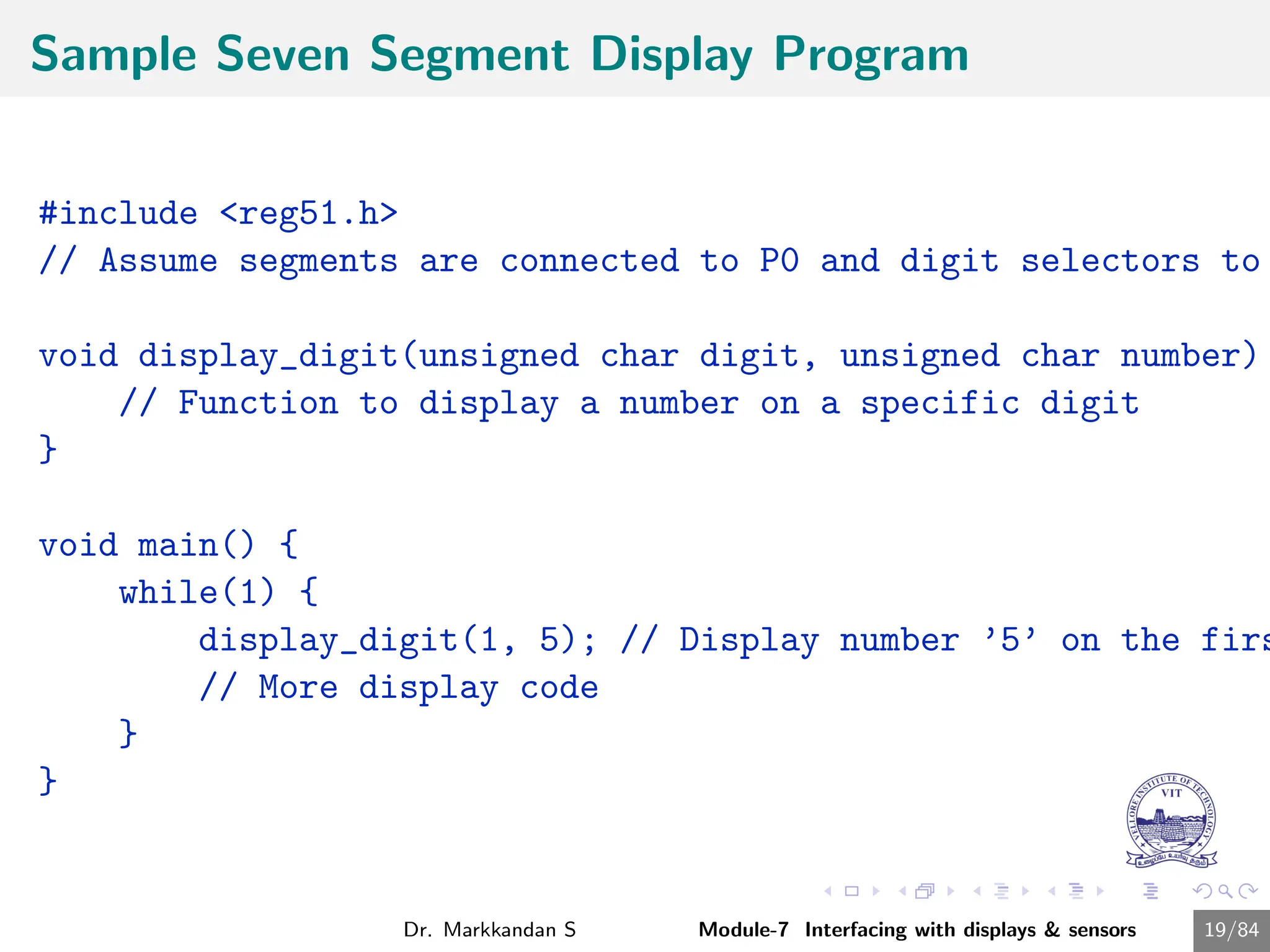
![Sample Seven Segment Display Program
1 First initialize all the segment hex values of the digits in an array.
unsigned char
arr[10]=0x3f,0x06,0x5b,0x4f,0x66,0x6d,0x7d,0x07,0x7f,0x67;
2 Now take for loop and assign array values to the PORT2 with some
time delay.
for (i=0;i<10;i++)
{
P2=arr[i];
delay_ms(500);
}
Dr. Markkandan S Module-7 Interfacing with displays & sensors 18/84](https://image.slidesharecdn.com/embeddedcmodule7-240716034846-94726bf2/85/Embedded-C-Programming-Module-7-Presentation-18-320.jpg)


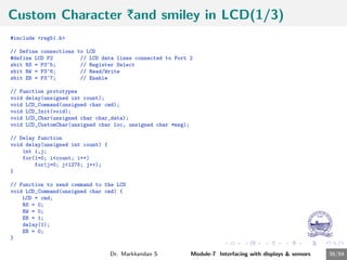
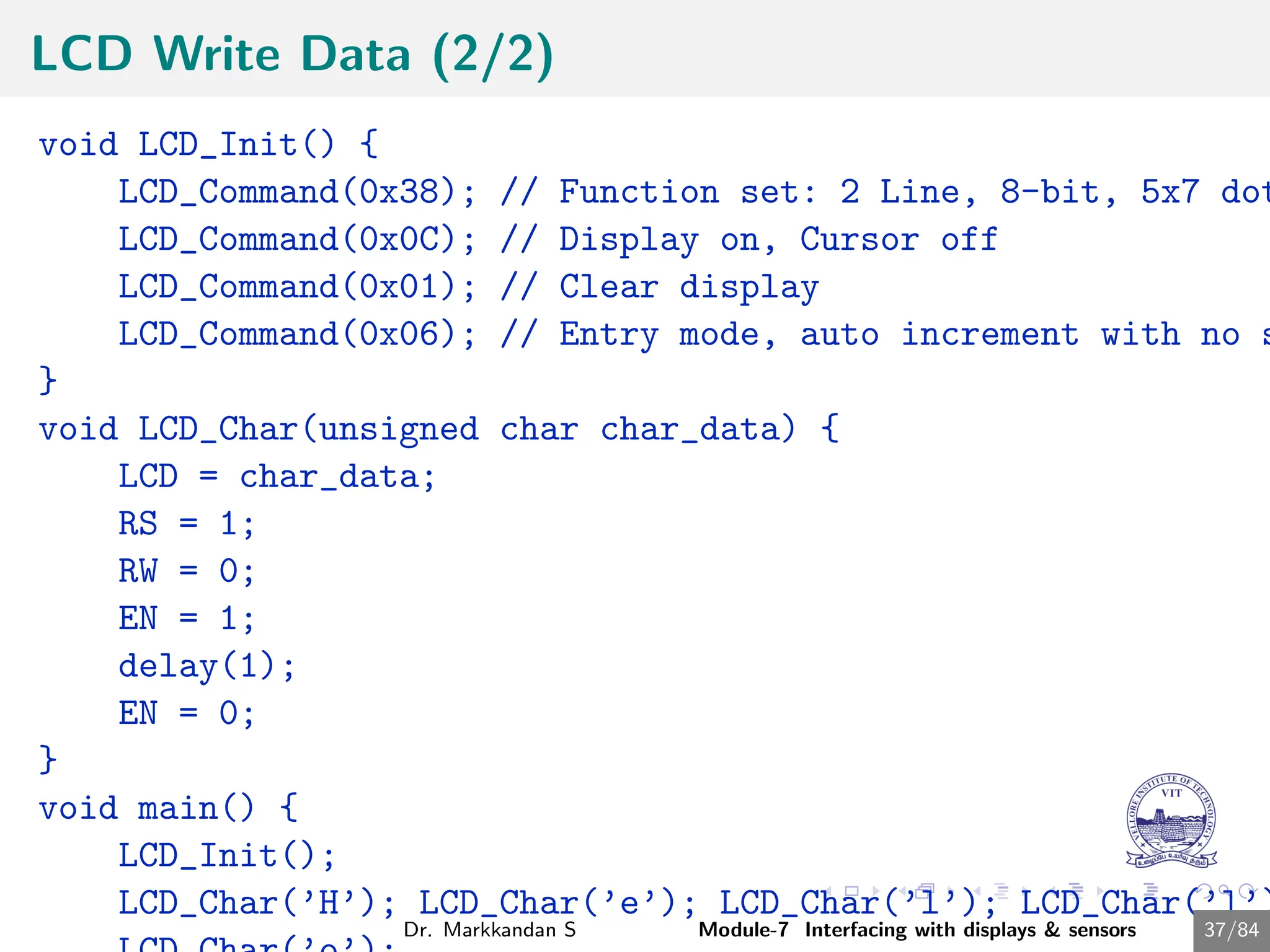
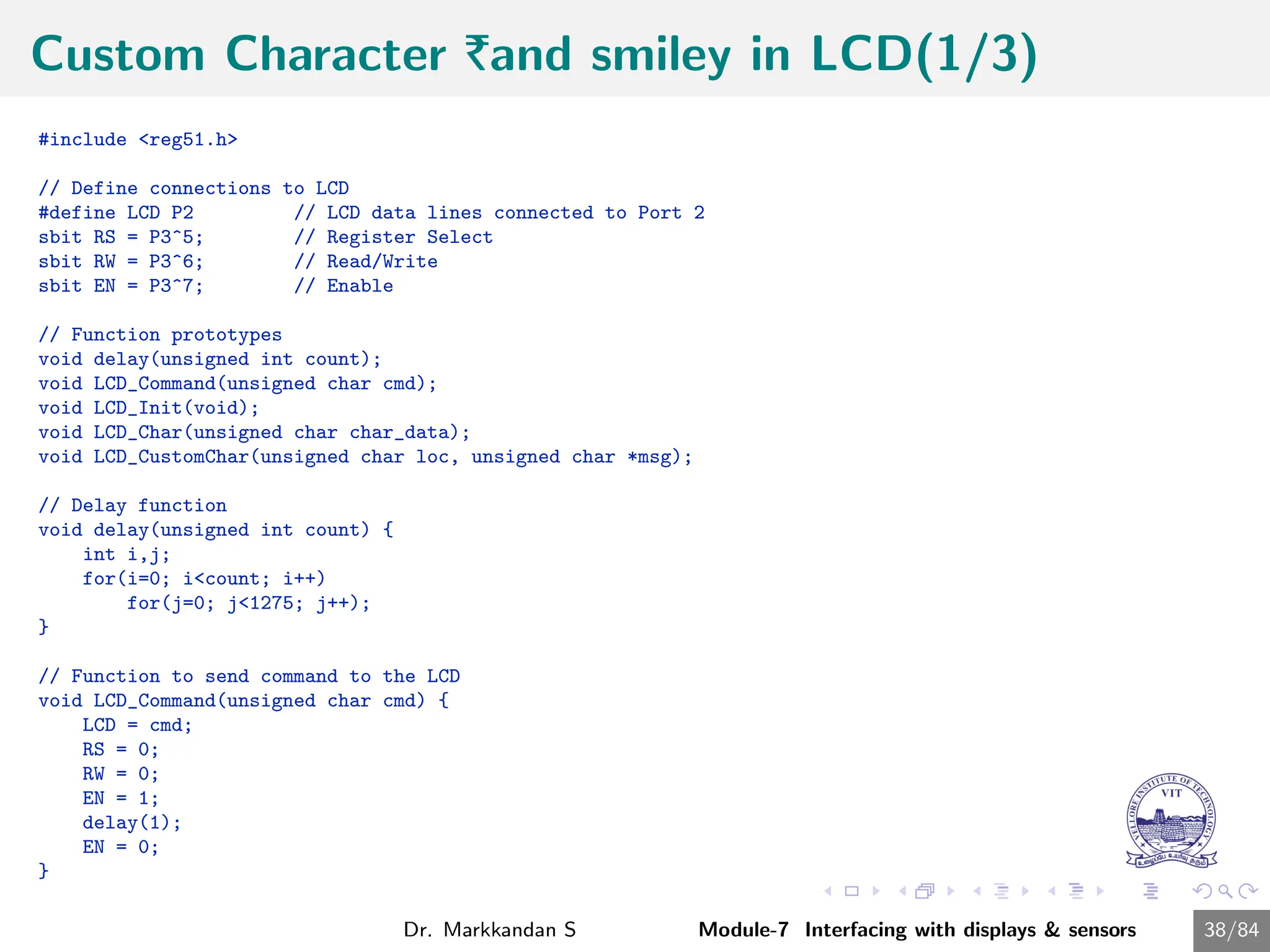
![Custom Character |and smiley in LCD(2/3)
// LCD initialization function
void LCD_Init() {
LCD_Command(0x38); // Function set: 2 Line, 8-bit, 5x7 dots
LCD_Command(0x0C); // Display on, Cursor off
LCD_Command(0x01); // Clear display
LCD_Command(0x06); // Entry mode, auto increment with no shift
}
// Function to display a single character
void LCD_Char(unsigned char char_data) {
LCD = char_data;
RS = 1;
RW = 0;
EN = 1;
delay(1);
EN = 0;
}
// Function to create custom characters
void LCD_CustomChar(unsigned char loc, unsigned char *msg) {
unsigned char i;
if(loc<8) {
LCD_Command(0x40 + (loc*8)); // Command 0x40 and onwards forces the device to point CGRAM address
for(i=0; i<8; i++) // Write 8 byte for generation of 1 character
LCD_Char(msg[i]);
}
}
Dr. Markkandan S Module-7 Interfacing with displays & sensors 39/84](https://image.slidesharecdn.com/embeddedcmodule7-240716034846-94726bf2/85/Embedded-C-Programming-Module-7-Presentation-39-320.jpg)
![Custom Character |and smiley in LCD(3/3)
void main() {
unsigned char Smiley[8] = {0x00, 0x00, 0x0A, 0x00, 0x11, 0x0E, 0
unsigned char Rupee[8] = {0x05, 0x07, 0x05, 0x1F, 0x05, 0x07, 0x
LCD_Init(); // Initialize LCD
// Create custom characters
LCD_CustomChar(0, Smiley);
LCD_CustomChar(1, Rupee);
// Display custom characters
LCD_Command(0x80); // Move cursor to the beginning of first lin
LCD_Char(0); // Display Smiley
LCD_Char(1); // Display Rupee symbol
while(1); // Infinite loop to keep displaying the char
}
Dr. Markkandan S Module-7 Interfacing with displays & sensors 40/84](https://image.slidesharecdn.com/embeddedcmodule7-240716034846-94726bf2/85/Embedded-C-Programming-Module-7-Presentation-40-320.jpg)


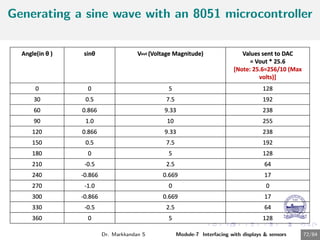
![Generating a sine wave using DAC in 8051
Programme
#includereg51.h
sfr DAC = 0x80; //Port P0 address
void main(){
int sin_value[12] = {128,192,238,255,238,192,128,64,17,
int i;
while(1){
//infinite loop for LED blinking
for(i = 0; i12; i++){
DAC = sin_value[i];
}
}
}
Dr. Markkandan S Module-7 Interfacing with displays sensors 73/84](https://image.slidesharecdn.com/embeddedcmodule7-240716034846-94726bf2/85/Embedded-C-Programming-Module-7-Presentation-74-320.jpg)
![Sine wave generation for every 10 degree
#includereg51.h
int main()
{
int j;
int c[37]={128,150,172,192,210,226,239,248,254,255,254,248,
239,226,210,192,172,150,128,106,84,64,46,30,17,8,2,0,2,8,17,
30,46,64,84,106,128};
while(1)
{
for(j=0;j36;j++)
{
P1=c[j];
}
P1=128;
}
}
Dr. Markkandan S Module-7 Interfacing with displays sensors 74/84](https://image.slidesharecdn.com/embeddedcmodule7-240716034846-94726bf2/85/Embedded-C-Programming-Module-7-Presentation-75-320.jpg)


![Sample Seven Segment Display Program
1 First initialize all the segment hex values of the digits in an array.
unsigned char
arr[10]=0x3f,0x06,0x5b,0x4f,0x66,0x6d,0x7d,0x07,0x7f,0x67;
2 Now take for loop and assign array values to the PORT2 with some
time delay.
for (i=0;i<10;i++)
{
P2=arr[i];
delay_ms(500);
}
Dr. Markkandan S Module-7 Interfacing with displays & sensors 18/84](https://image.slidesharecdn.com/embeddedcmodule7-240716034846-94726bf2/75/Embedded-C-Programming-Module-7-Presentation-18-2048.jpg)


![Custom Character |and smiley in LCD(2/3)
// LCD initialization function
void LCD_Init() {
LCD_Command(0x38); // Function set: 2 Line, 8-bit, 5x7 dots
LCD_Command(0x0C); // Display on, Cursor off
LCD_Command(0x01); // Clear display
LCD_Command(0x06); // Entry mode, auto increment with no shift
}
// Function to display a single character
void LCD_Char(unsigned char char_data) {
LCD = char_data;
RS = 1;
RW = 0;
EN = 1;
delay(1);
EN = 0;
}
// Function to create custom characters
void LCD_CustomChar(unsigned char loc, unsigned char *msg) {
unsigned char i;
if(loc<8) {
LCD_Command(0x40 + (loc*8)); // Command 0x40 and onwards forces the device to point CGRAM address
for(i=0; i<8; i++) // Write 8 byte for generation of 1 character
LCD_Char(msg[i]);
}
}
Dr. Markkandan S Module-7 Interfacing with displays & sensors 39/84](https://image.slidesharecdn.com/embeddedcmodule7-240716034846-94726bf2/75/Embedded-C-Programming-Module-7-Presentation-39-2048.jpg)
![Custom Character |and smiley in LCD(3/3)
void main() {
unsigned char Smiley[8] = {0x00, 0x00, 0x0A, 0x00, 0x11, 0x0E, 0
unsigned char Rupee[8] = {0x05, 0x07, 0x05, 0x1F, 0x05, 0x07, 0x
LCD_Init(); // Initialize LCD
// Create custom characters
LCD_CustomChar(0, Smiley);
LCD_CustomChar(1, Rupee);
// Display custom characters
LCD_Command(0x80); // Move cursor to the beginning of first lin
LCD_Char(0); // Display Smiley
LCD_Char(1); // Display Rupee symbol
while(1); // Infinite loop to keep displaying the char
}
Dr. Markkandan S Module-7 Interfacing with displays & sensors 40/84](https://image.slidesharecdn.com/embeddedcmodule7-240716034846-94726bf2/75/Embedded-C-Programming-Module-7-Presentation-40-2048.jpg)


![Generating a sine wave using DAC in 8051
Programme
#includereg51.h
sfr DAC = 0x80; //Port P0 address
void main(){
int sin_value[12] = {128,192,238,255,238,192,128,64,17,
int i;
while(1){
//infinite loop for LED blinking
for(i = 0; i12; i++){
DAC = sin_value[i];
}
}
}
Dr. Markkandan S Module-7 Interfacing with displays sensors 73/84](https://image.slidesharecdn.com/embeddedcmodule7-240716034846-94726bf2/75/Embedded-C-Programming-Module-7-Presentation-74-2048.jpg)
![Sine wave generation for every 10 degree
#includereg51.h
int main()
{
int j;
int c[37]={128,150,172,192,210,226,239,248,254,255,254,248,
239,226,210,192,172,150,128,106,84,64,46,30,17,8,2,0,2,8,17,
30,46,64,84,106,128};
while(1)
{
for(j=0;j36;j++)
{
P1=c[j];
}
P1=128;
}
}
Dr. Markkandan S Module-7 Interfacing with displays sensors 74/84](https://image.slidesharecdn.com/embeddedcmodule7-240716034846-94726bf2/75/Embedded-C-Programming-Module-7-Presentation-75-2048.jpg)


![Embedded System[586]](https://cdn.slidesharecdn.com/ss_thumbnails/viisemesterindustrialtrainingreportpawan586-171104035355-thumbnail.jpg?width=600ounds&width=560&fit=bounds)


