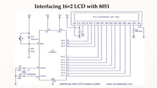
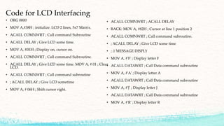
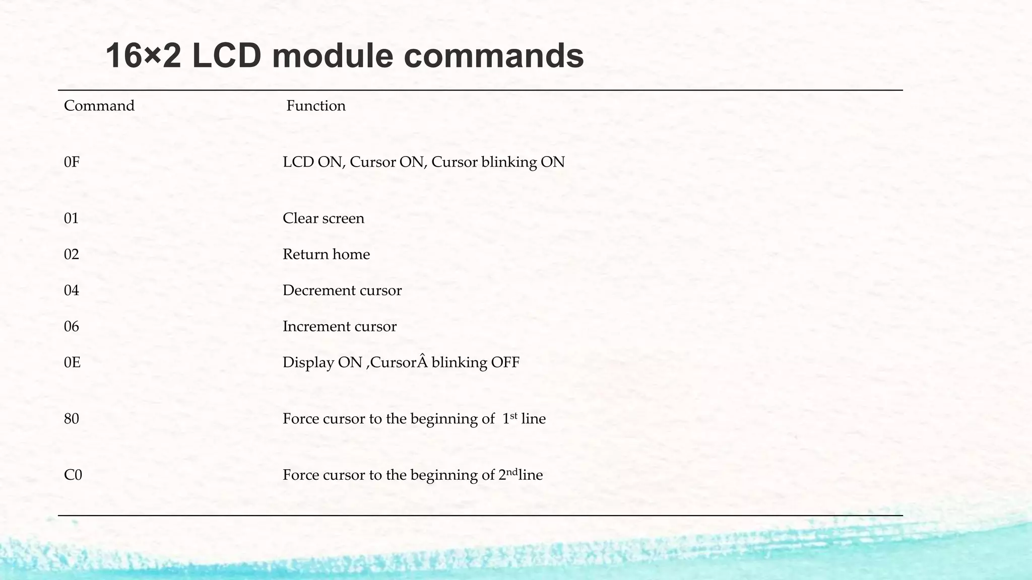
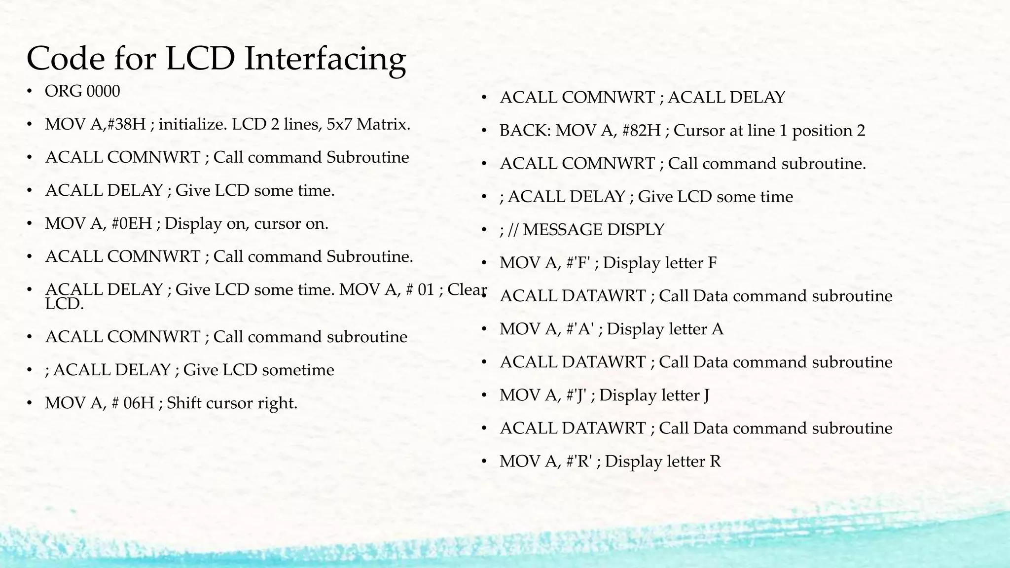
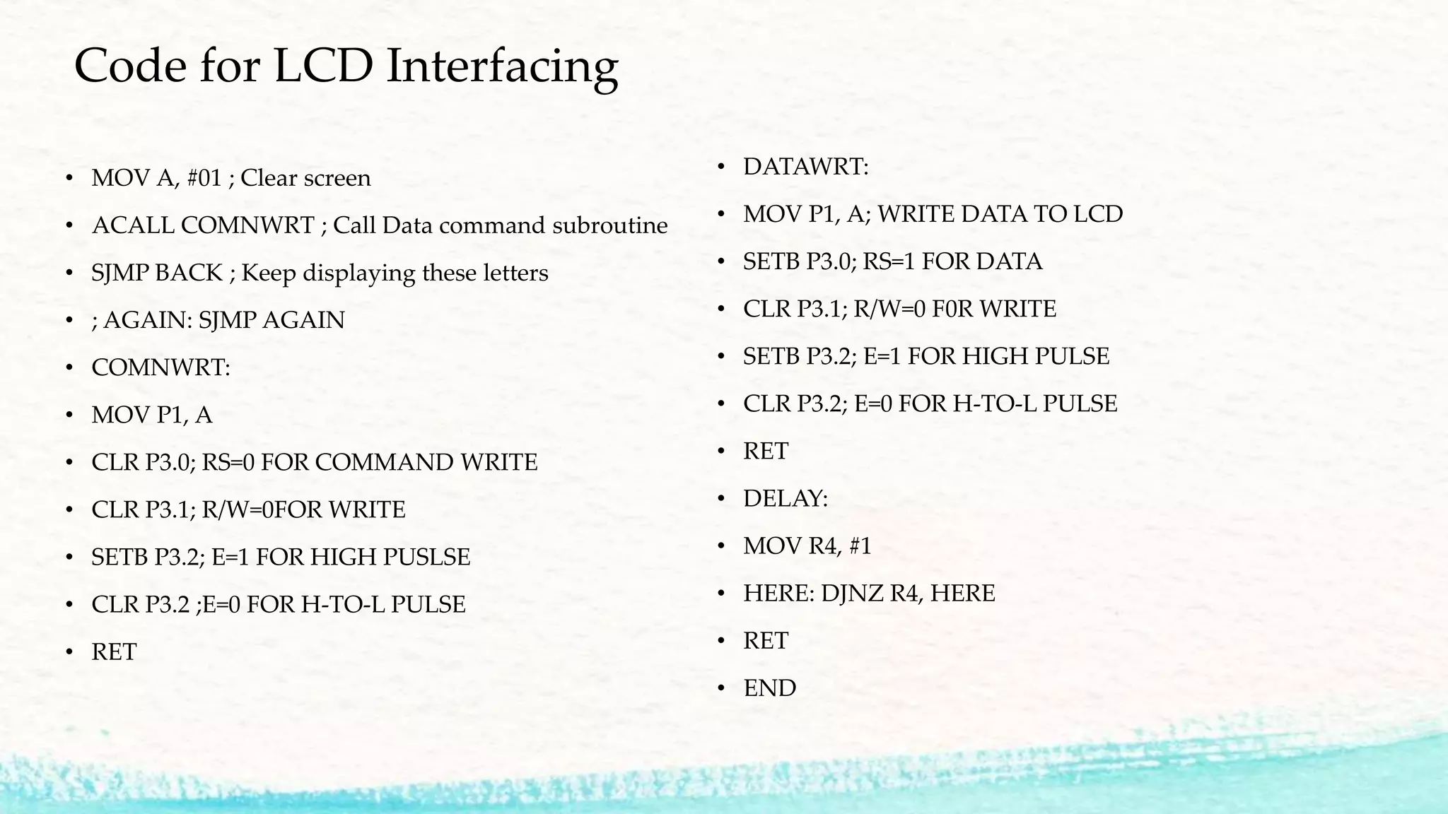
This document discusses interfacing a 16x2 LCD display with an 8051 microcontroller. It includes sections on LCD components and operation, the 16x2 LCD module pinout and commands, initialization steps, sending data to the LCD, contrast control, timing diagrams for read/write operations, and an example code for interfacing the LCD with 8051 microcontroller ports and registers. The code initializes the LCD, clears the display, positions the cursor, and continuously displays the letters "FAJR".
Group Members
• HasnainYaseen EE161021
• Sufyan Nasir EE161036
• Muhammad Ahtsham EE161012
• Usman Ashraf EE161046
4.
Introduction
• LCD displayis an inevitable part in almost all embedded projects and this
pre is about interfacing a 16×2 LCD with 8051 microcontroller.
• Many guys take it hard to interface LCD module with the 8051 but the fact
is that if you learn it properly, its a very easy job and by knowing it you
can easily design embedded projects like
• Digital voltmeter / ammeter,
• Digital clock,
• Home automation displays,
• Status indicator display,
• Display for music players etc.
5.
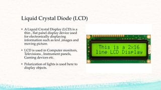
Liquid Crystal Diode(LCD)
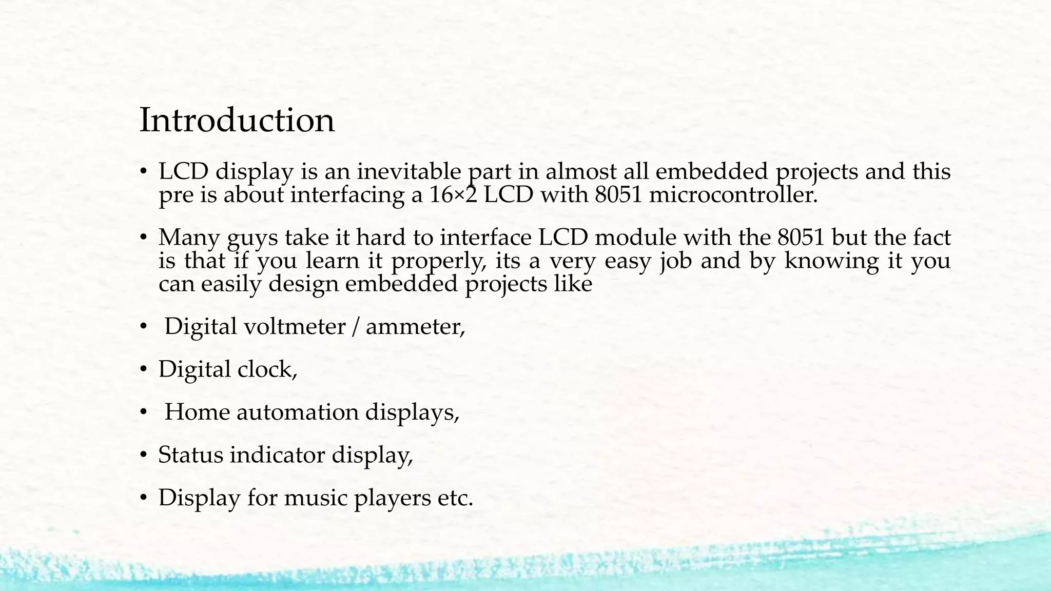
• A Liquid Crystal Display (LCD) is a
thin , flat panel display device used
for electronically displaying
information such as text ,images and
moving picture.
• LCD is used in Computer monitors,
Televisions , Instrument panels,
Gaming devices etc.
• Polarization of lights is used here to
display objects.
6.
Why LCD ?
•Smaller size —LCDs occupy approximately 60 percent less space than CRT
displays an important feature when office space is limited.
• Lower power consumption—LCDs typically consume about half the
power and emit much less heat than CRT displays.
• Lighter weight —LCDs weigh approximately 70 percent less than CRT
displays of comparable size.
• No electromagnetic fields —LCDs do not emit electromagnetic fields and
are not susceptible to them. Thus, they are suitable for use in areas where CRTs
cannot be used.
• Longer life —LCDs have a longer useful life than CRTs.
7.
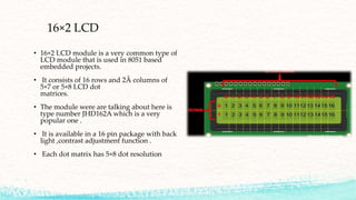
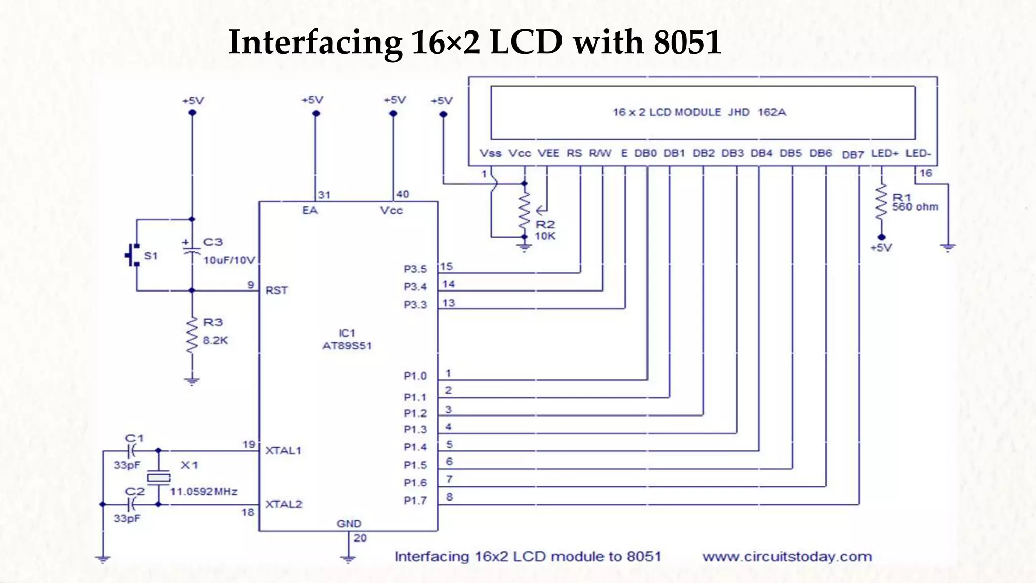
16×2 LCD
• 16×2LCD module is a very common type of
LCD module that is used in 8051 based
embedded projects.
• It consists of 16 rows and 2Â columns of
5×7 or 5×8 LCD dot
matrices.
• The module were are talking about here is
type number JHD162A which is a very
popular one .
• It is available in a 16 pin package with back
light ,contrast adjustment function .
• Each dot matrix has 5×8 dot resolution
8.
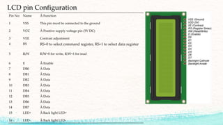
LCD pin Configuration
PinNo: Name  Function
1 VSS This pin must be connected to the ground
2 VCC Â Positive supply voltage pin (5V DC)
3 VEE Contrast adjustment
4 RS RS=0 to select command register, RS=1 to select data register
5 R/W R/W=0 for write, R/W=1 for read
6 E Â Enable
7 DB0 Â Data
8 DB1 Â Data
9 DB2 Â Data
10 DB3 Â Data
11 DB4 Â Data
12 DB5 Â Data
13 DB6 Â Data
14 DB7 Â Data
15 LED+ Â Back light LED+
16 LED- Â Back light LED-
9.
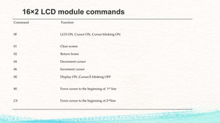
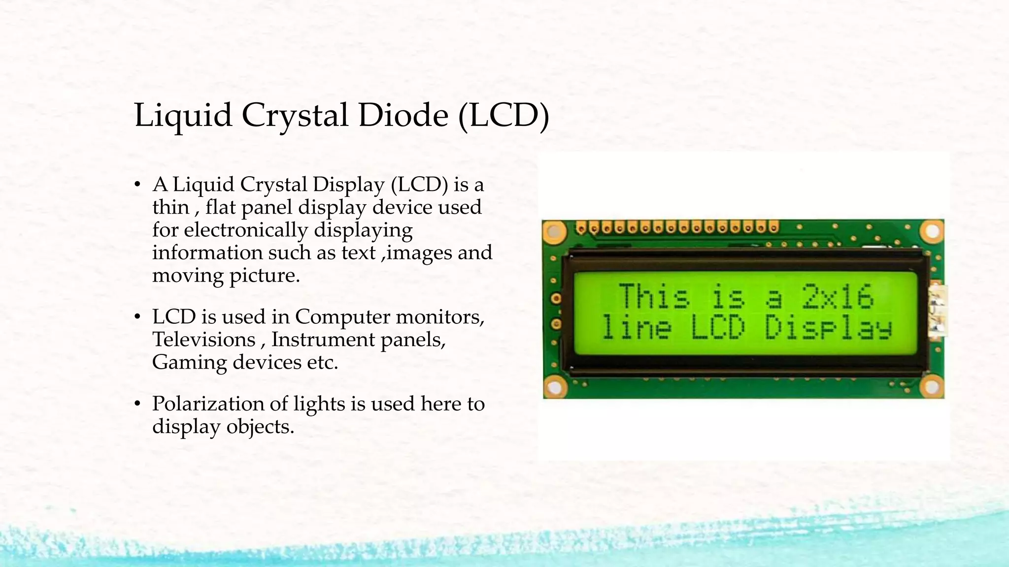
16×2 LCD modulecommands
Command Function
0F LCD ON, Cursor ON, Cursor blinking ON
01 Clear screen
02 Return home
04 Decrement cursor
06 Increment cursor
0E Display ON ,Cursor blinking OFF
80 Force cursor to the beginning of 1st line
C0 Force cursor to the beginning of 2ndline
10.
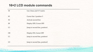
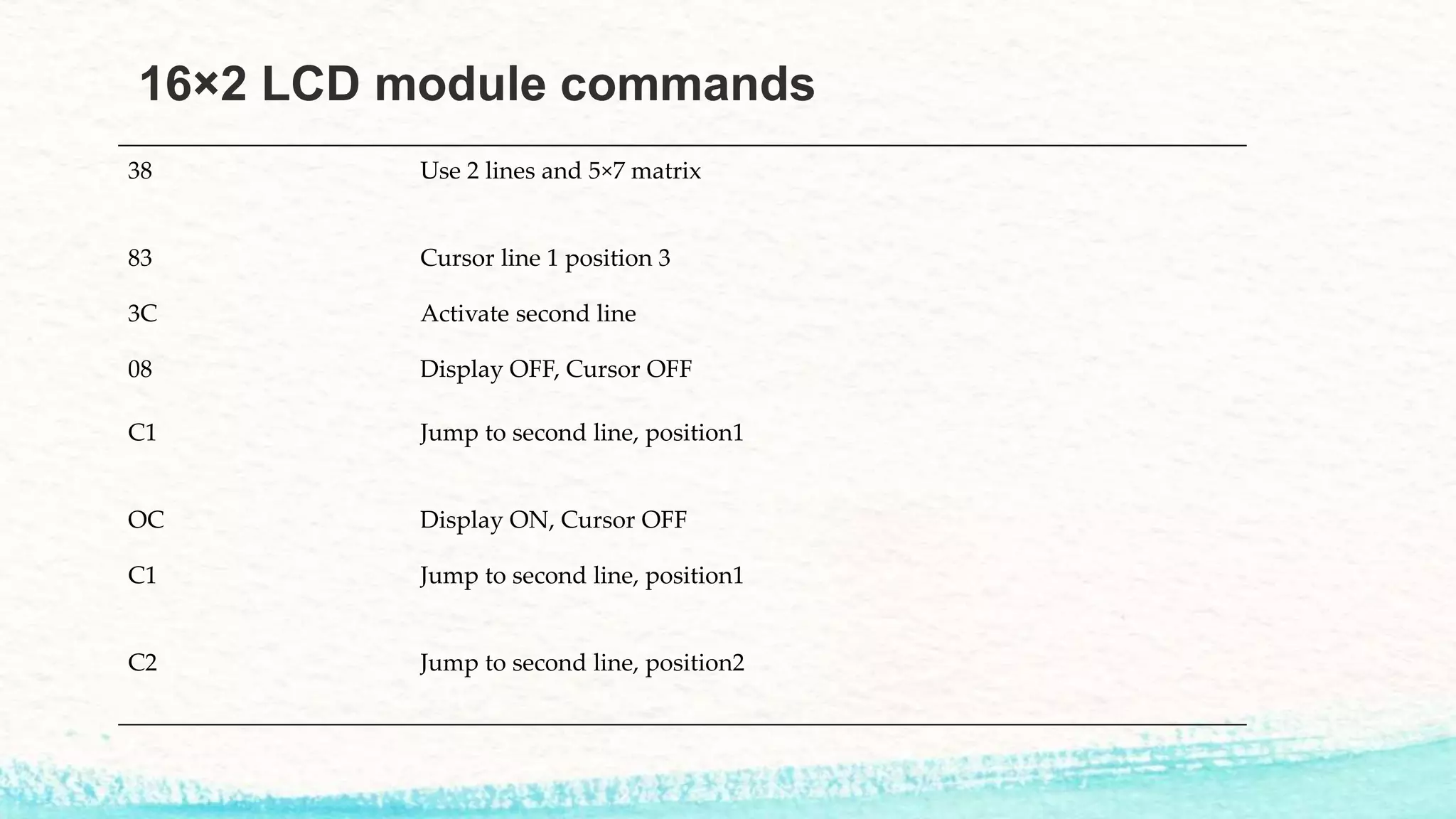
16×2 LCD modulecommands
38 Use 2 lines and 5×7 matrix
83 Cursor line 1 position 3
3C Activate second line
08 Display OFF, Cursor OFF
C1 Jump to second line, position1
OC Display ON, Cursor OFF
C1 Jump to second line, position1
C2 Jump to second line, position2
11.
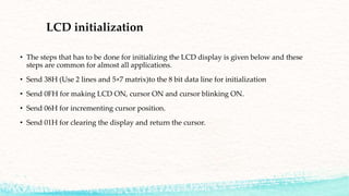
LCD initialization
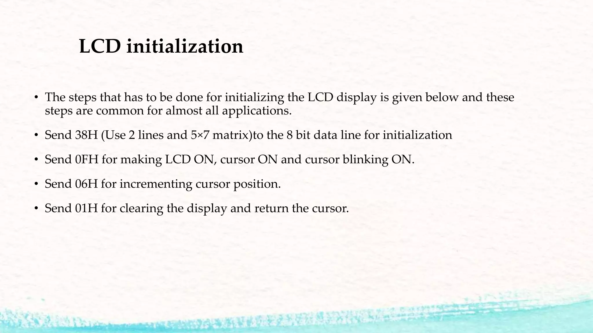
• Thesteps that has to be done for initializing the LCD display is given below and these
steps are common for almost all applications.
• Send 38H (Use 2 lines and 5×7 matrix)to the 8 bit data line for initialization
• Send 0FH for making LCD ON, cursor ON and cursor blinking ON.
• Send 06H for incrementing cursor position.
• Send 01H for clearing the display and return the cursor.
12.
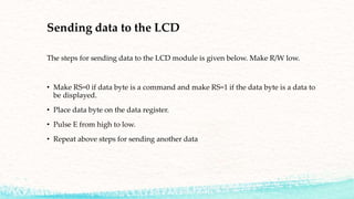
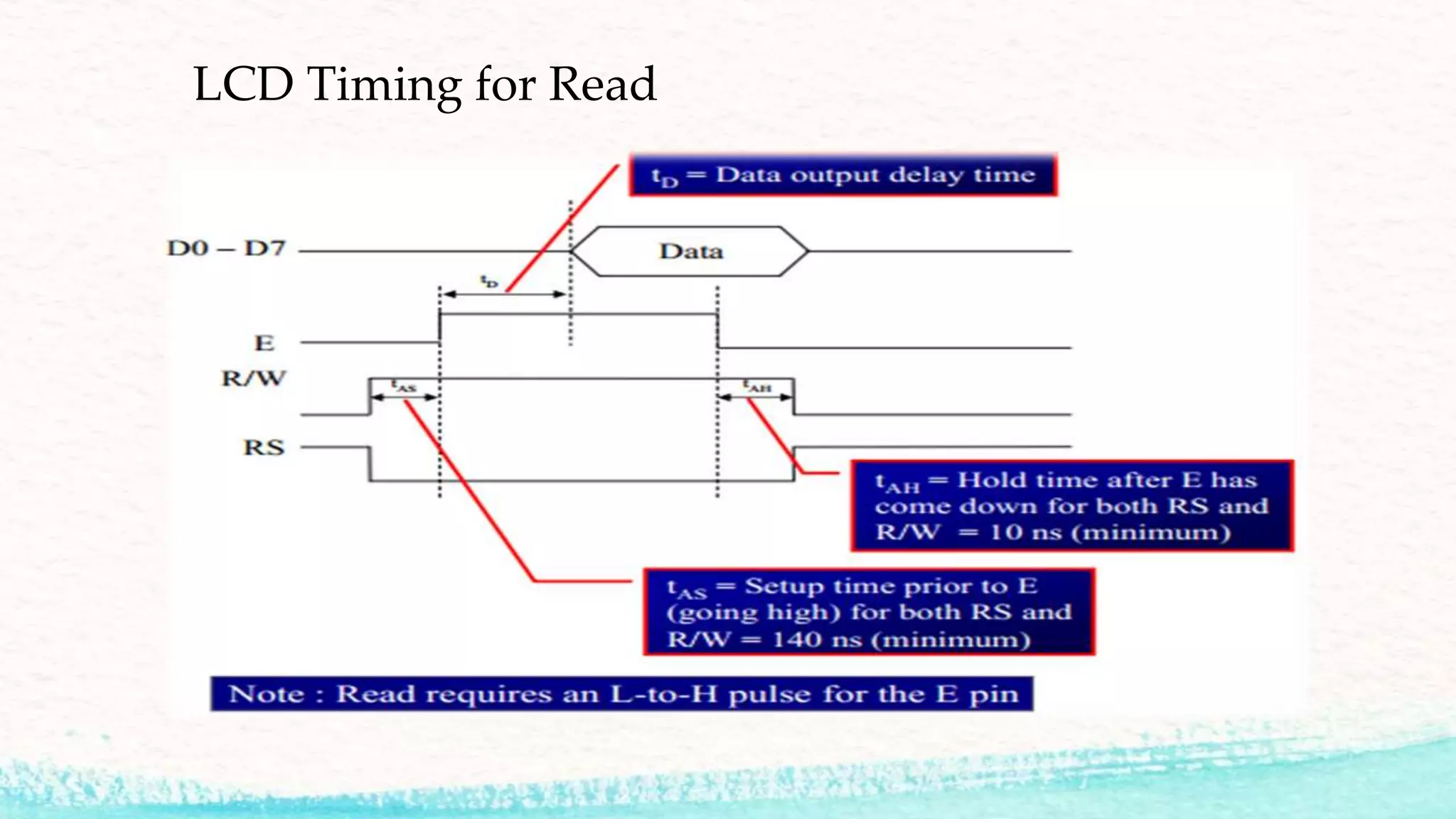
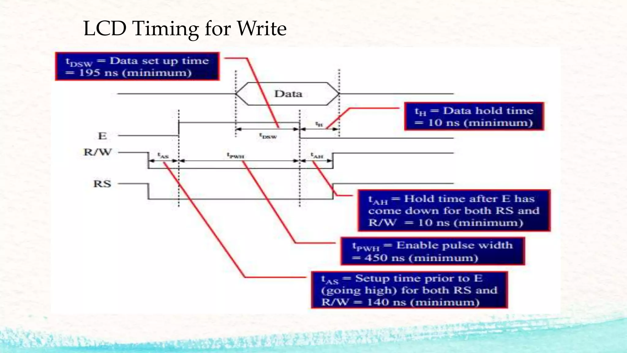
Sending data tothe LCD
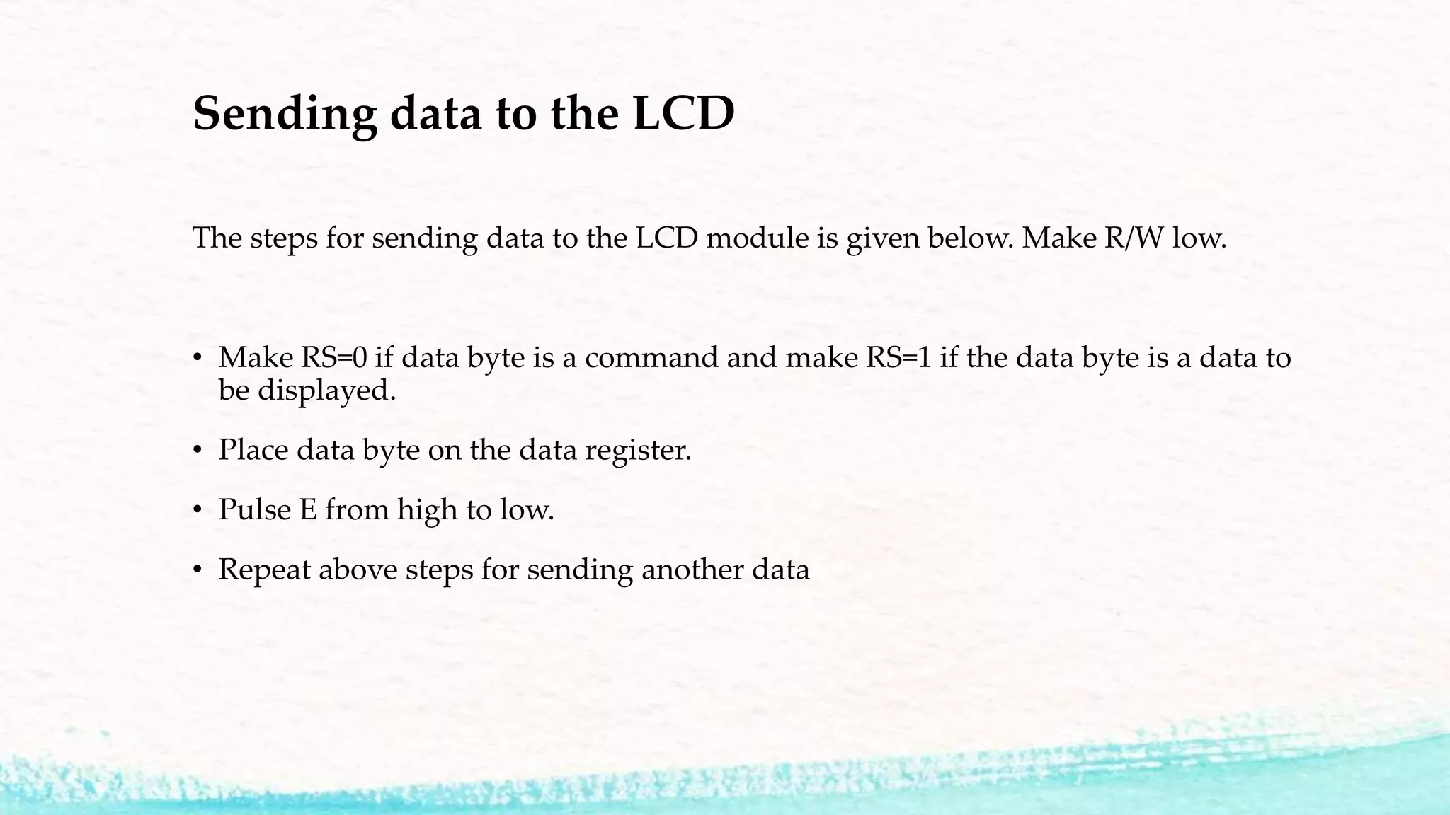
The steps for sending data to the LCD module is given below. Make R/W low.
• Make RS=0 if data byte is a command and make RS=1 if the data byte is a data to
be displayed.
• Place data byte on the data register.
• Pulse E from high to low.
• Repeat above steps for sending another data
13.
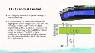
LCD Contrast Control
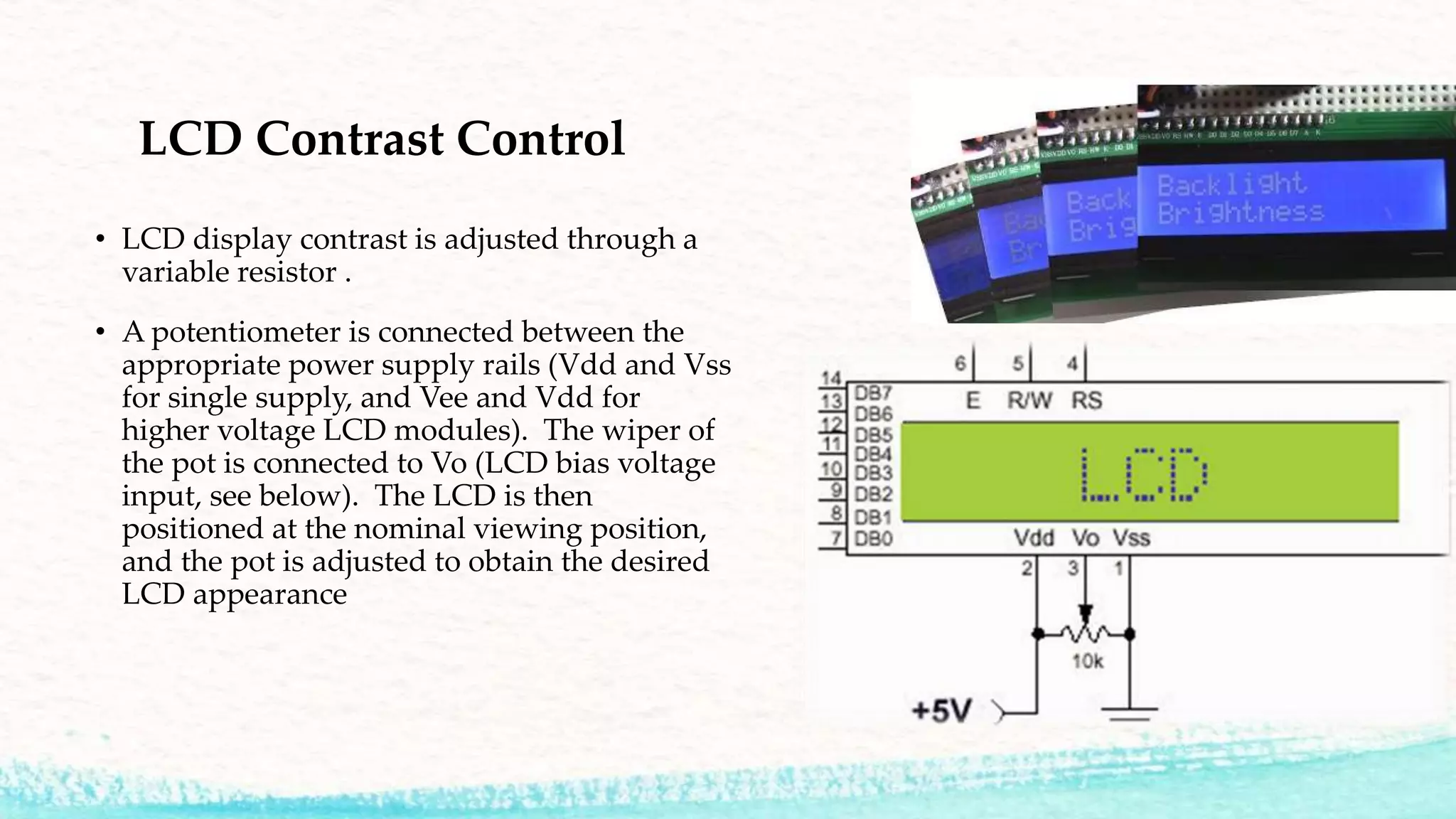
•LCD display contrast is adjusted through a
variable resistor .
• A potentiometer is connected between the
appropriate power supply rails (Vdd and Vss
for single supply, and Vee and Vdd for
higher voltage LCD modules). The wiper of
the pot is connected to Vo (LCD bias voltage
input, see below). The LCD is then
positioned at the nominal viewing position,
and the pot is adjusted to obtain the desired
LCD appearance