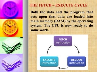
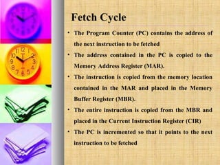
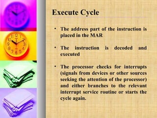
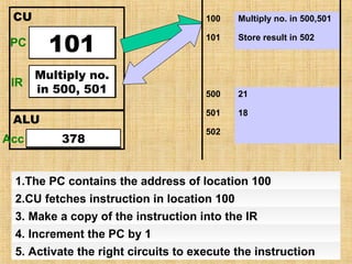
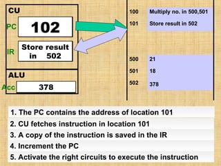
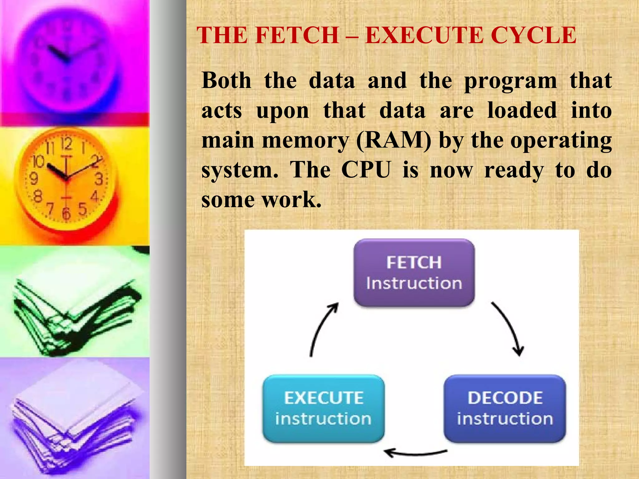
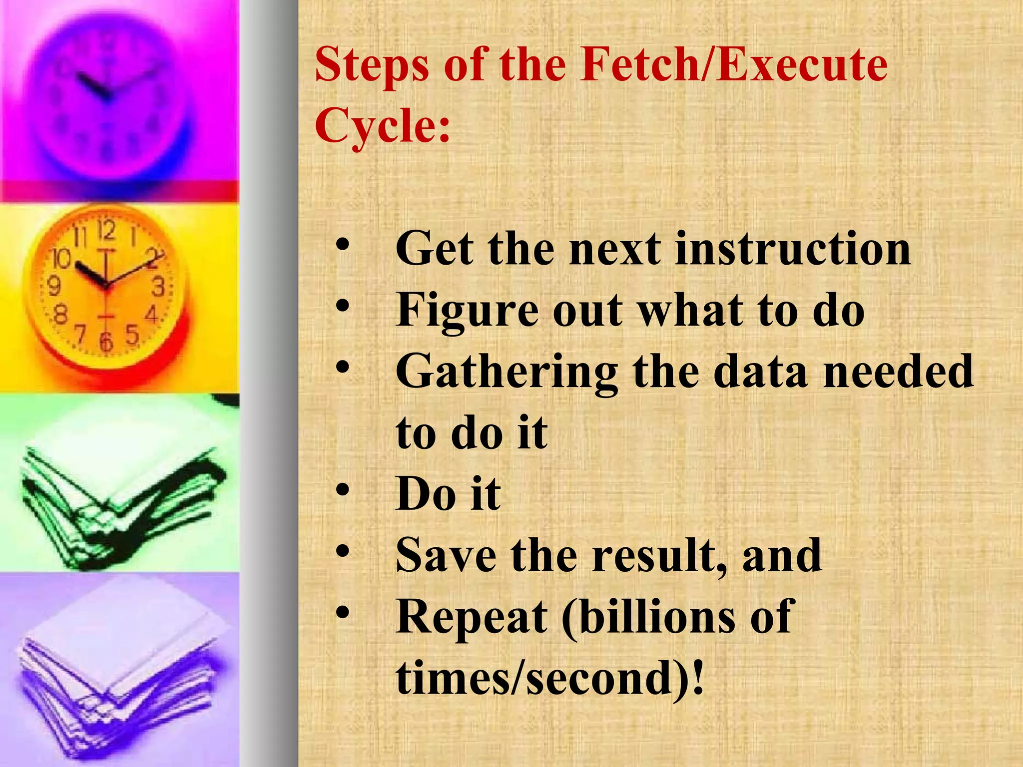
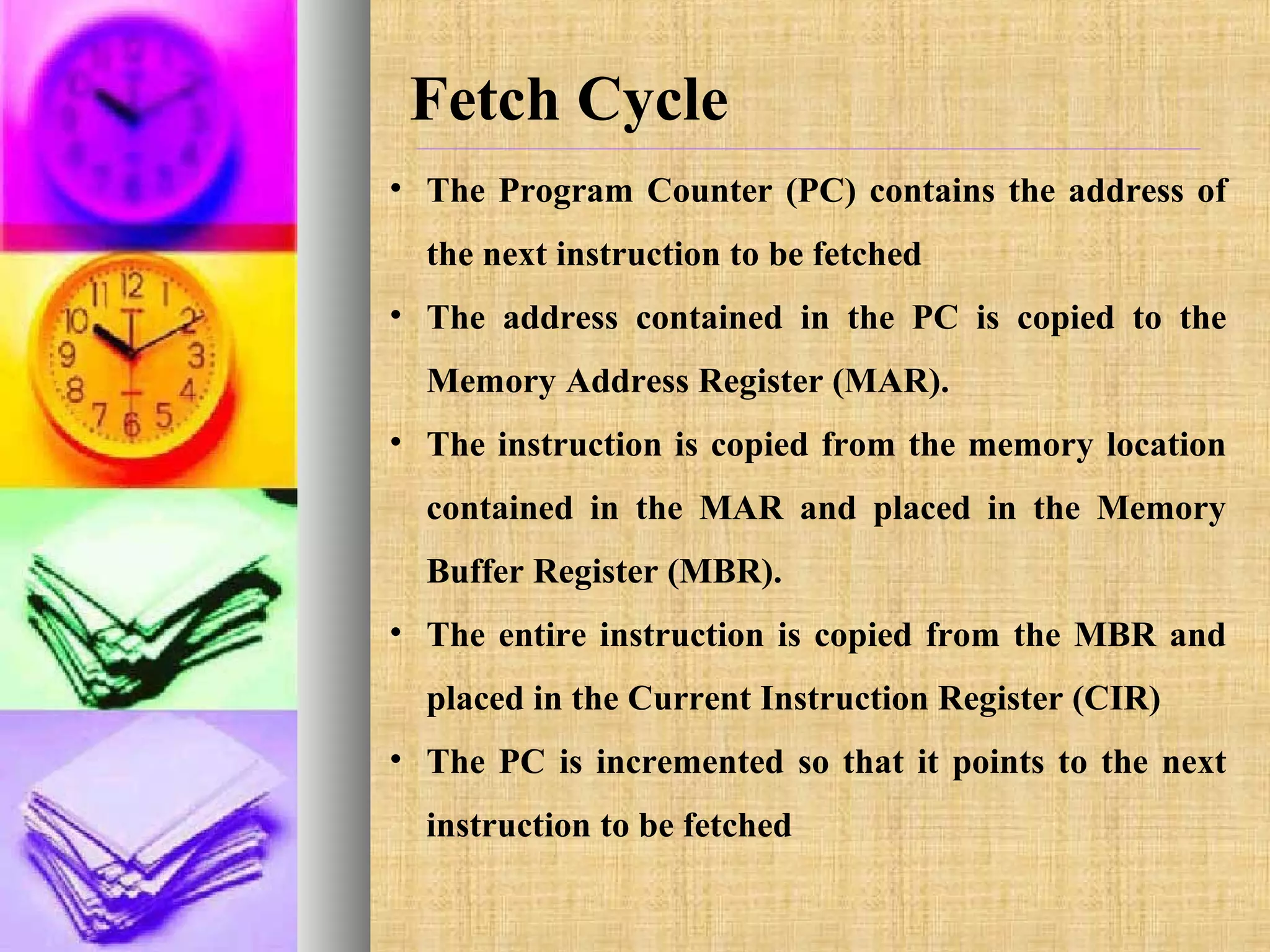
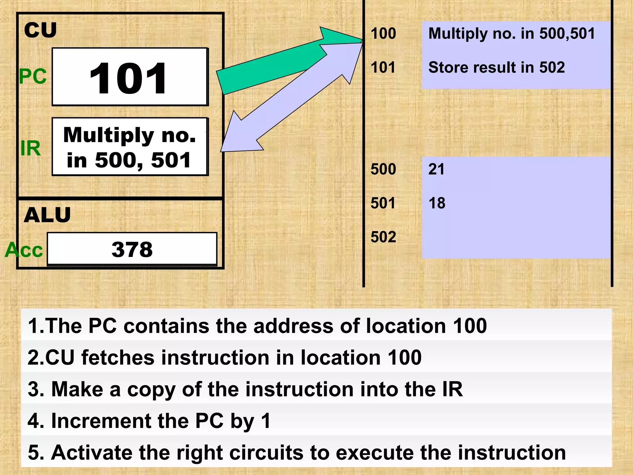
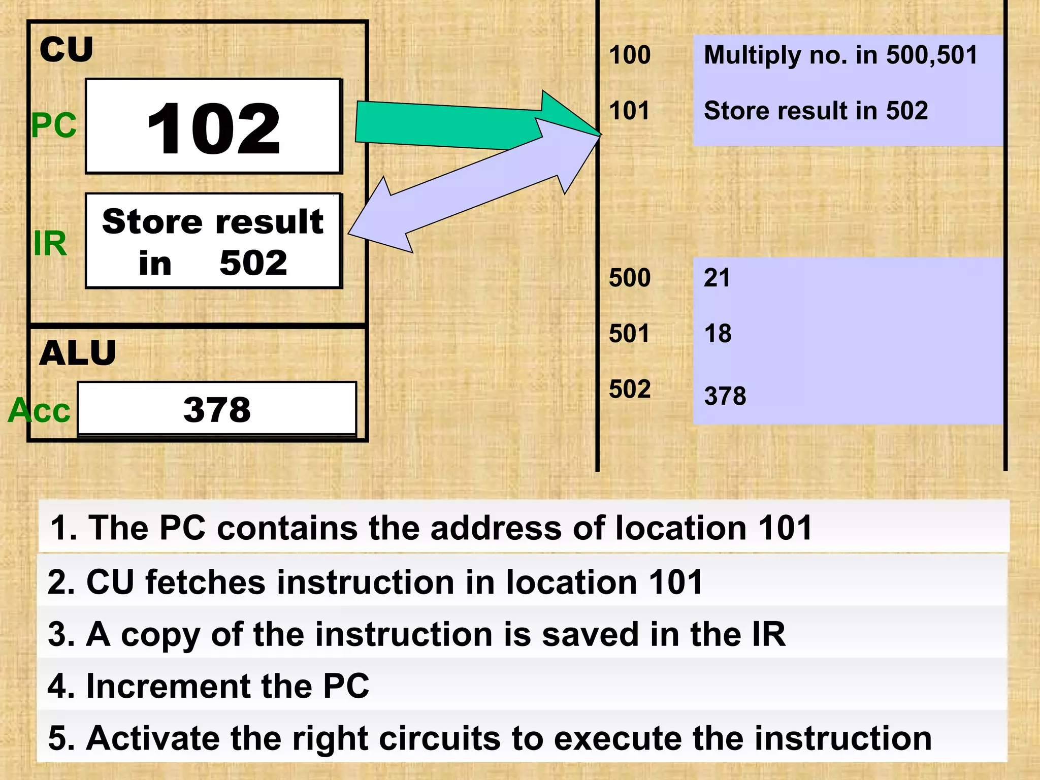
KEMBAR78
Fetch decode-execute presentation | PPT
Fetch-Decode-Execute
Cycle
THE FETCH – EXECUTE CYCLE
Both the data and the program that
acts upon that data are loaded into
main memory (RAM) by the operating
system. The CPU is now ready to do
some work.
Steps of the Fetch/Execute
Cycle:
• Get the next instruction
• Figure out what to do
• Gathering the data needed
to do it
• Do it
• Save the result, and
• Repeat (billions of
times/second)!
Fetch Cycle
• The Program Counter (PC) contains the address of
the next instruction to be fetched
• The address contained in the PC is copied to the
Memory Address Register (MAR).
• The instruction is copied from the memory location
contained in the MAR and placed in the Memory
Buffer Register (MBR).
• The entire instruction is copied from the MBR and
placed in the Current Instruction Register (CIR)
• The PC is incremented so that it points to the next
instruction to be fetched
Execute Cycle
• The address part of the instruction is
placed in the MAR
• The instruction
executed

is

decoded

and

• The processor checks for interrupts
(signals from devices or other sources
seeking the attention of the processor)
and either branches to the relevant
interrupt service routine or starts the
cycle again.
CU

100

101
100

PC

Program
Counter

IR

Multiply no.
Instruction
in 500, 501
Register

ALU
Acc Accumulator
378

Multiply no. in 500,501

101

Store result in 502

500

21

501

18

502

1.The PC contains the address of location 100
2.CU fetches instruction in location 100
3. Make a copy of the instruction into the IR
4. Increment the PC by 1
5. Activate the right circuits to execute the instruction
CU
PC

100

102
101

Program
Counter

Store result
Multiply no.
Instruction
IR
inin 502
500, 501
Register
ALU
Acc Accumulator
378

Multiply no. in 500,501

101

Store result in 502

500

21

501

18

502

378

1. The PC contains the address of location 101
2. CU fetches instruction in location 101
3. A copy of the instruction is saved in the IR
4. Increment the PC
5. Activate the right circuits to execute the instruction

Fetch decode-execute presentation

  • 1.
  • 2.
    THE FETCH –EXECUTE CYCLE Both the data and the program that acts upon that data are loaded into main memory (RAM) by the operating system. The CPU is now ready to do some work.
  • 3.
    Steps of theFetch/Execute Cycle: • Get the next instruction • Figure out what to do • Gathering the data needed to do it • Do it • Save the result, and • Repeat (billions of times/second)!
  • 4.
    Fetch Cycle • TheProgram Counter (PC) contains the address of the next instruction to be fetched • The address contained in the PC is copied to the Memory Address Register (MAR). • The instruction is copied from the memory location contained in the MAR and placed in the Memory Buffer Register (MBR). • The entire instruction is copied from the MBR and placed in the Current Instruction Register (CIR) • The PC is incremented so that it points to the next instruction to be fetched
  • 5.
    Execute Cycle • Theaddress part of the instruction is placed in the MAR • The instruction executed is decoded and • The processor checks for interrupts (signals from devices or other sources seeking the attention of the processor) and either branches to the relevant interrupt service routine or starts the cycle again.
  • 6.
    CU 100 101 100 PC Program Counter IR Multiply no. Instruction in 500,501 Register ALU Acc Accumulator 378 Multiply no. in 500,501 101 Store result in 502 500 21 501 18 502 1.The PC contains the address of location 100 2.CU fetches instruction in location 100 3. Make a copy of the instruction into the IR 4. Increment the PC by 1 5. Activate the right circuits to execute the instruction
  • 7.
    CU PC 100 102 101 Program Counter Store result Multiply no. Instruction IR inin502 500, 501 Register ALU Acc Accumulator 378 Multiply no. in 500,501 101 Store result in 502 500 21 501 18 502 378 1. The PC contains the address of location 101 2. CU fetches instruction in location 101 3. A copy of the instruction is saved in the IR 4. Increment the PC 5. Activate the right circuits to execute the instruction