Download as PDF, PPTX

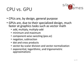
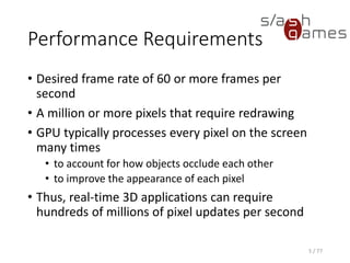


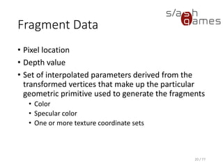
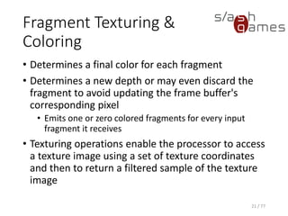

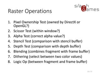
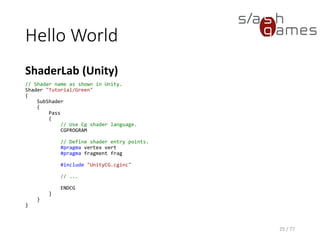

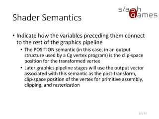
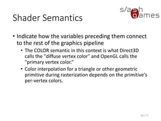
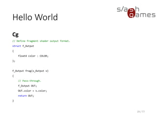
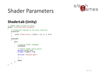

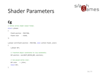
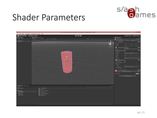
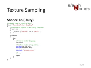

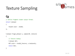
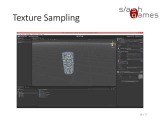
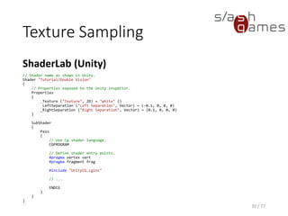

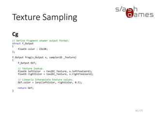
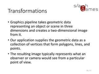


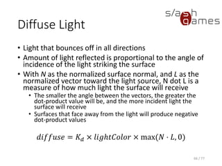
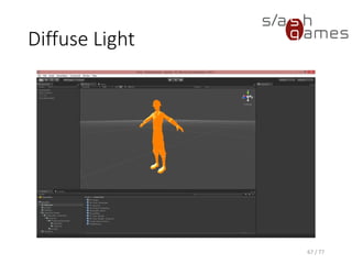
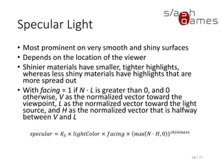

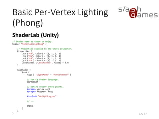
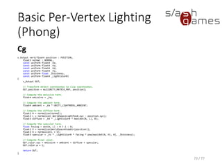

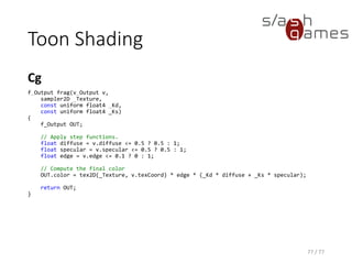
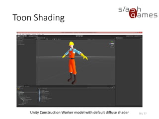


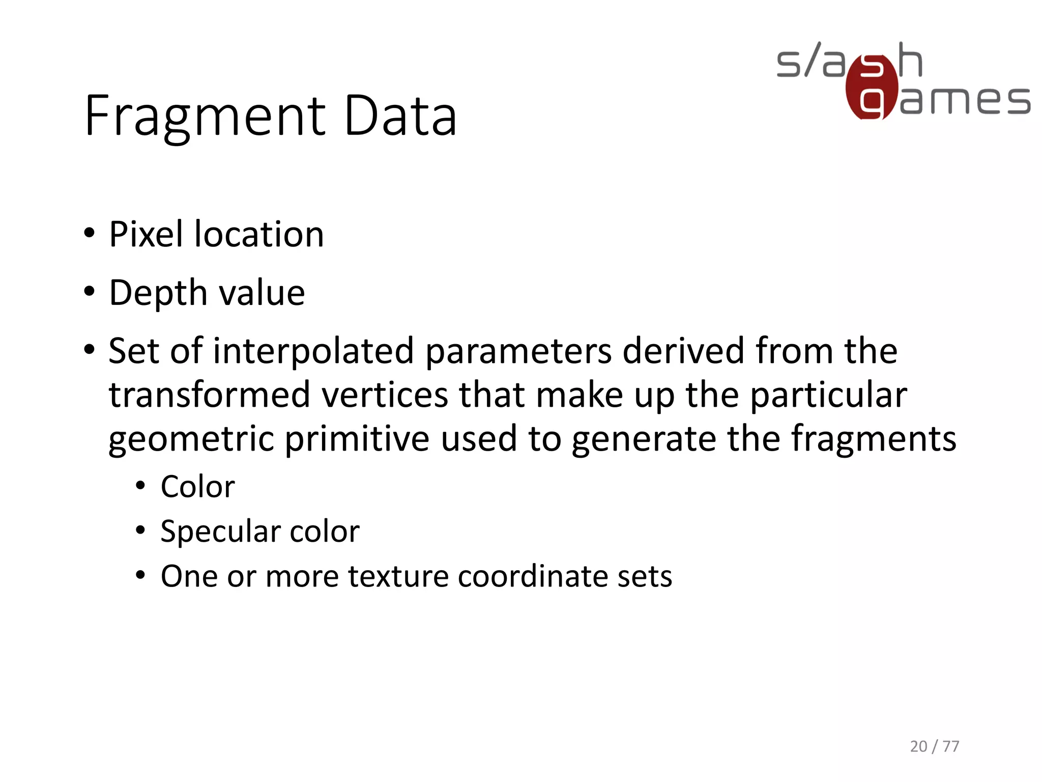
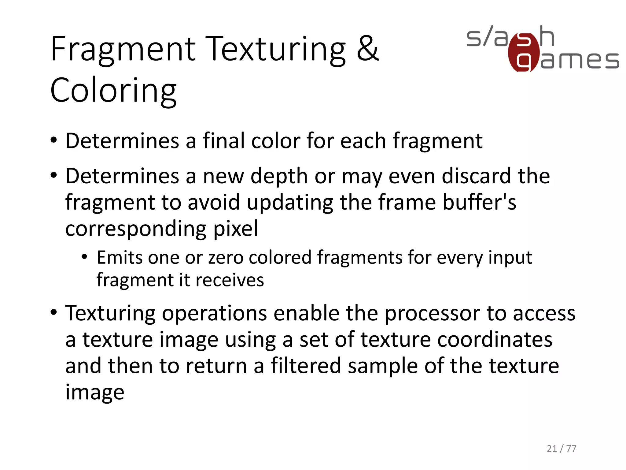
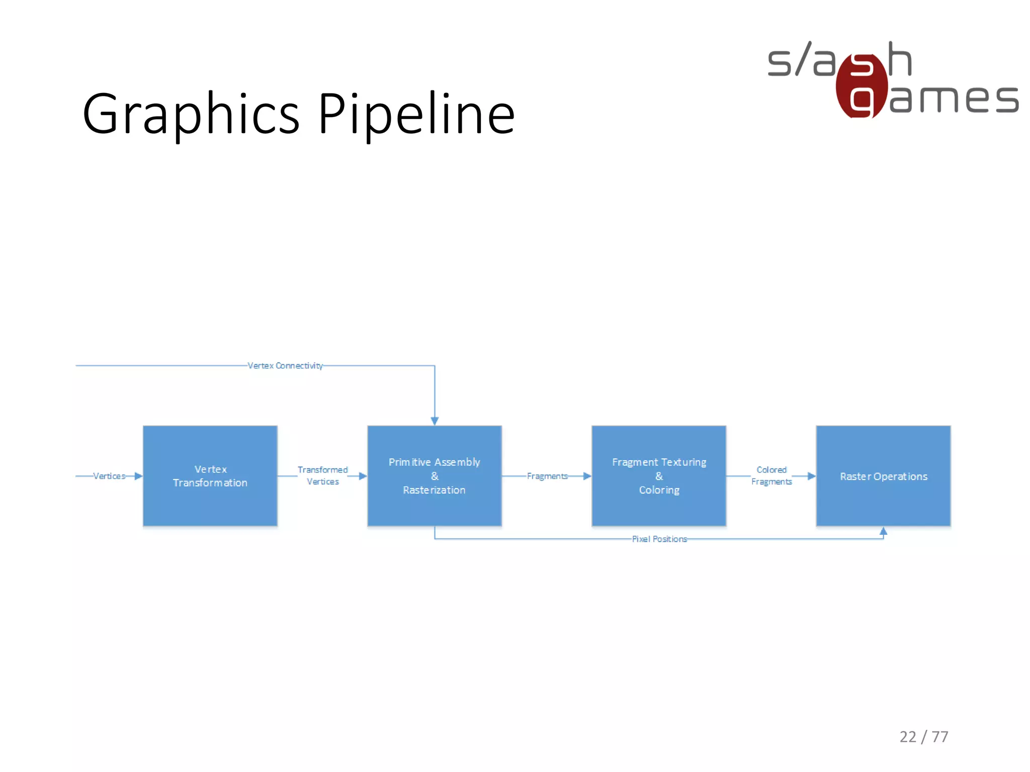
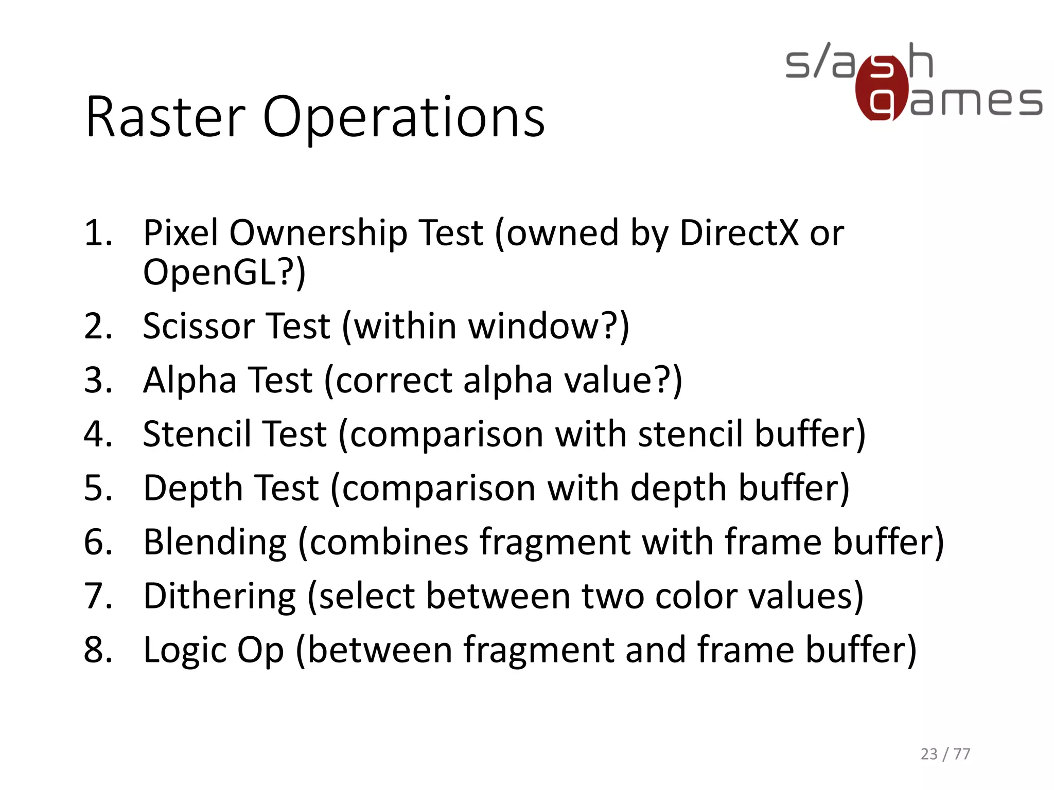
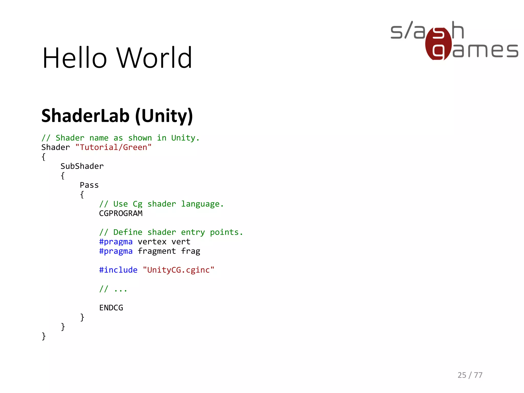
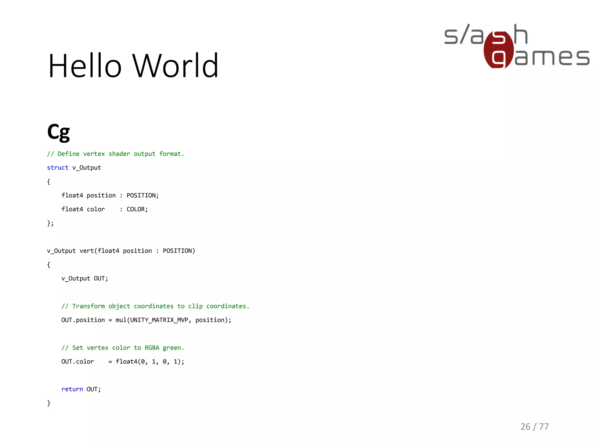
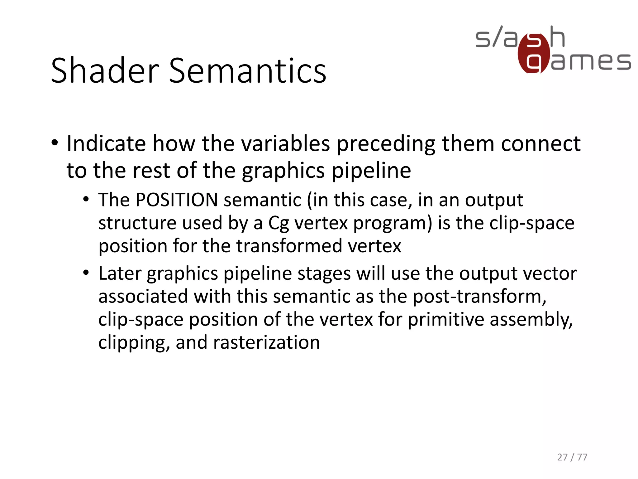


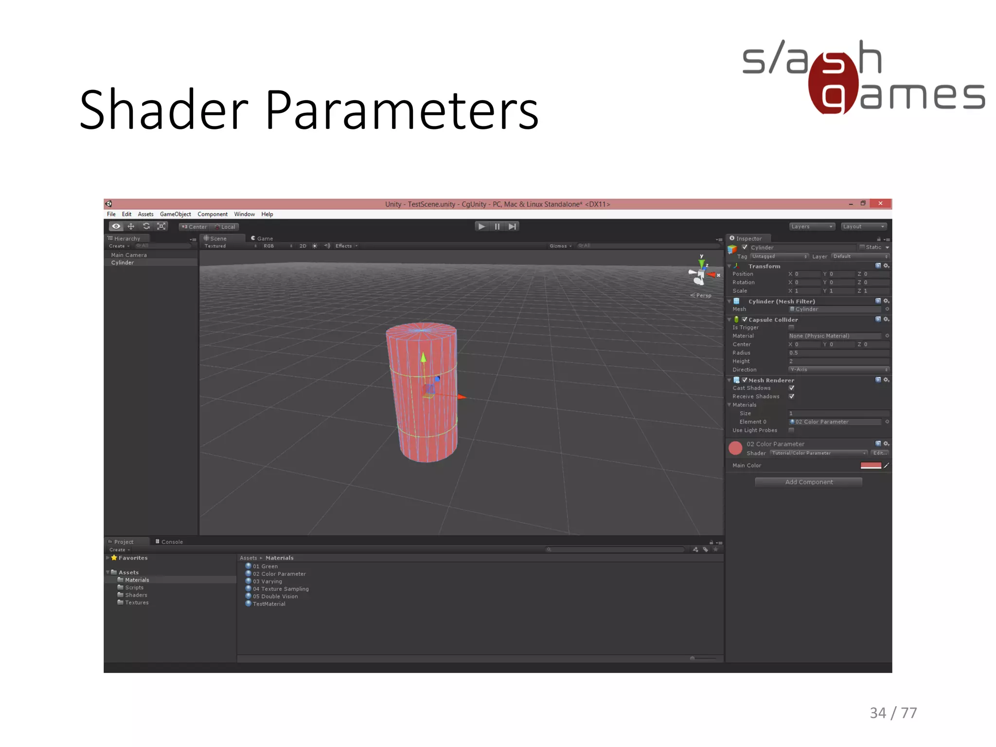
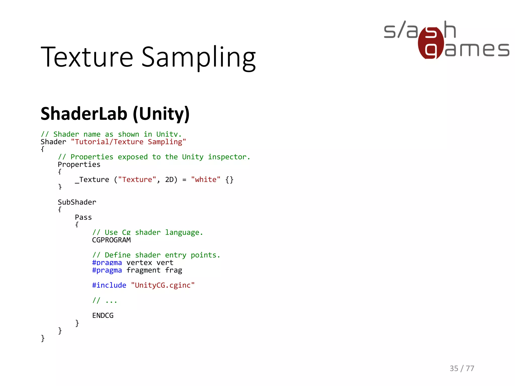
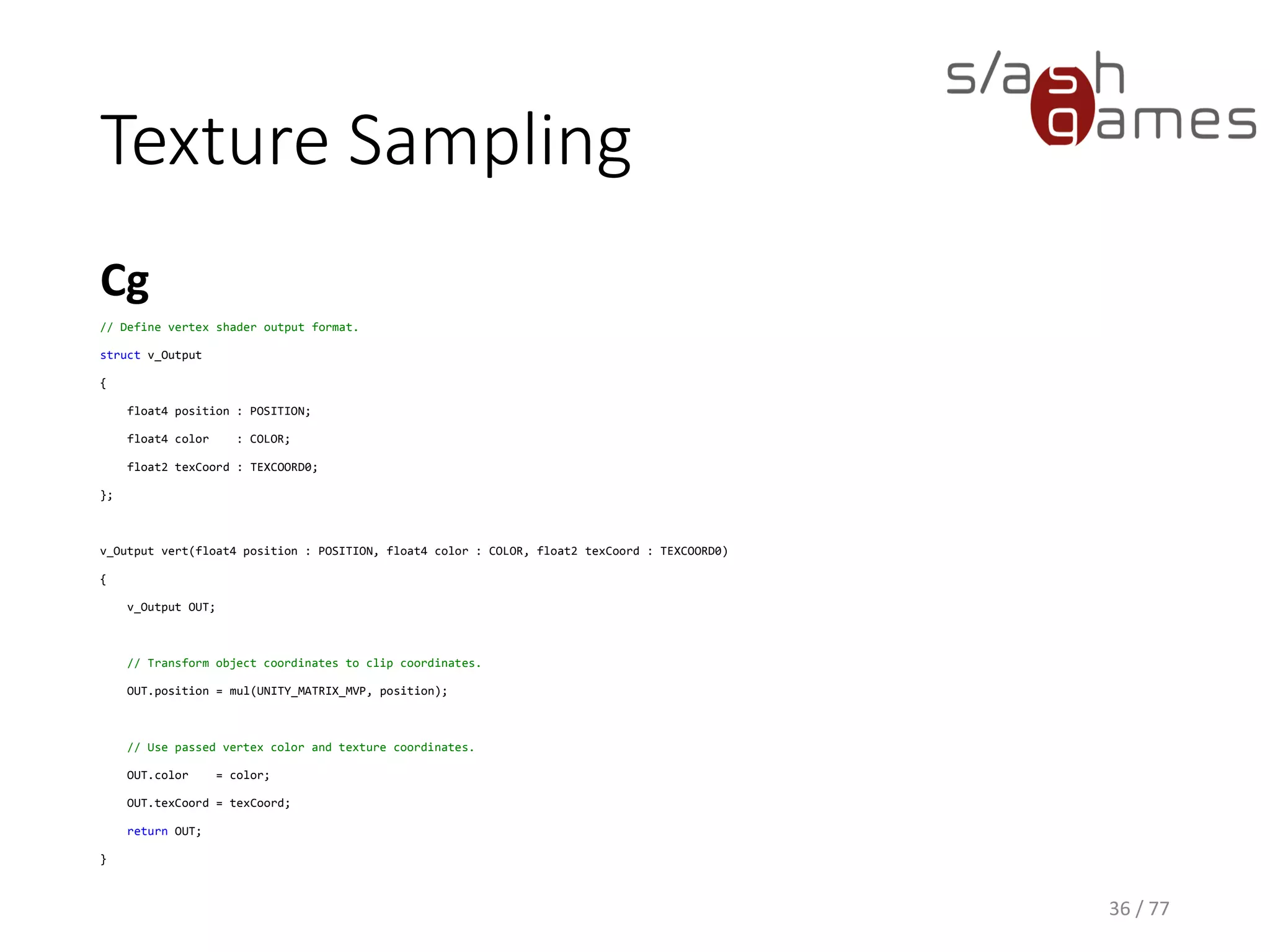
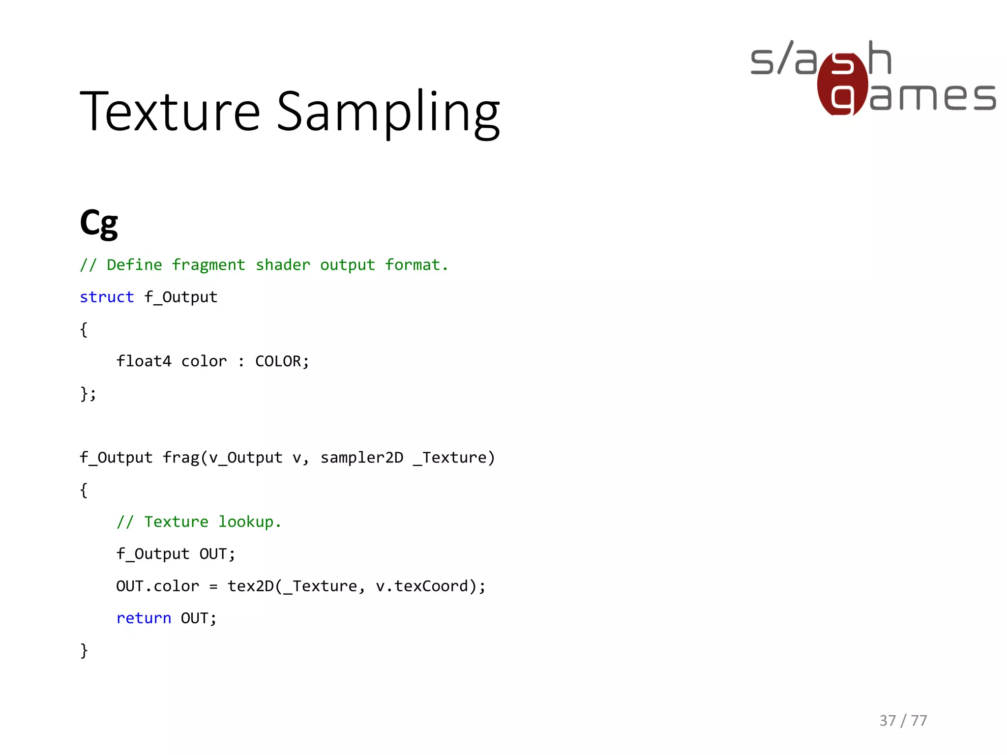
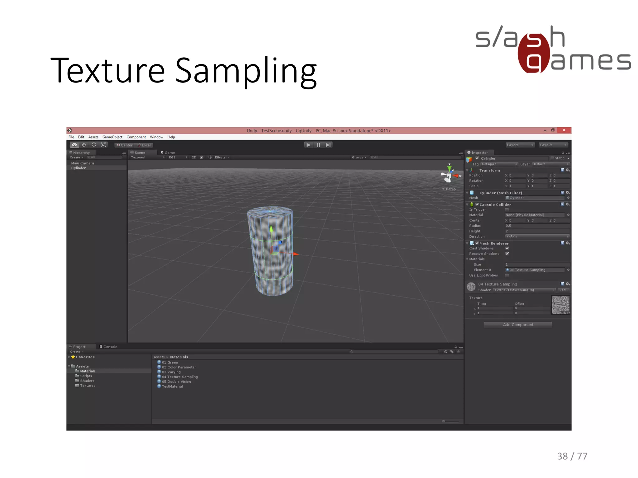
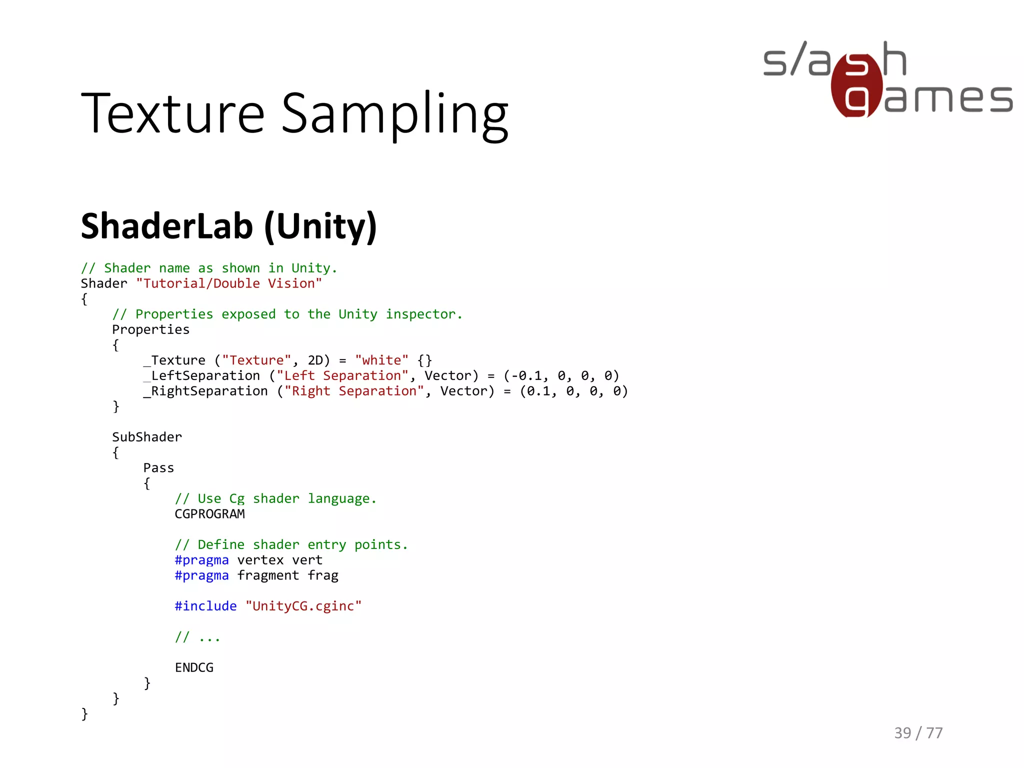
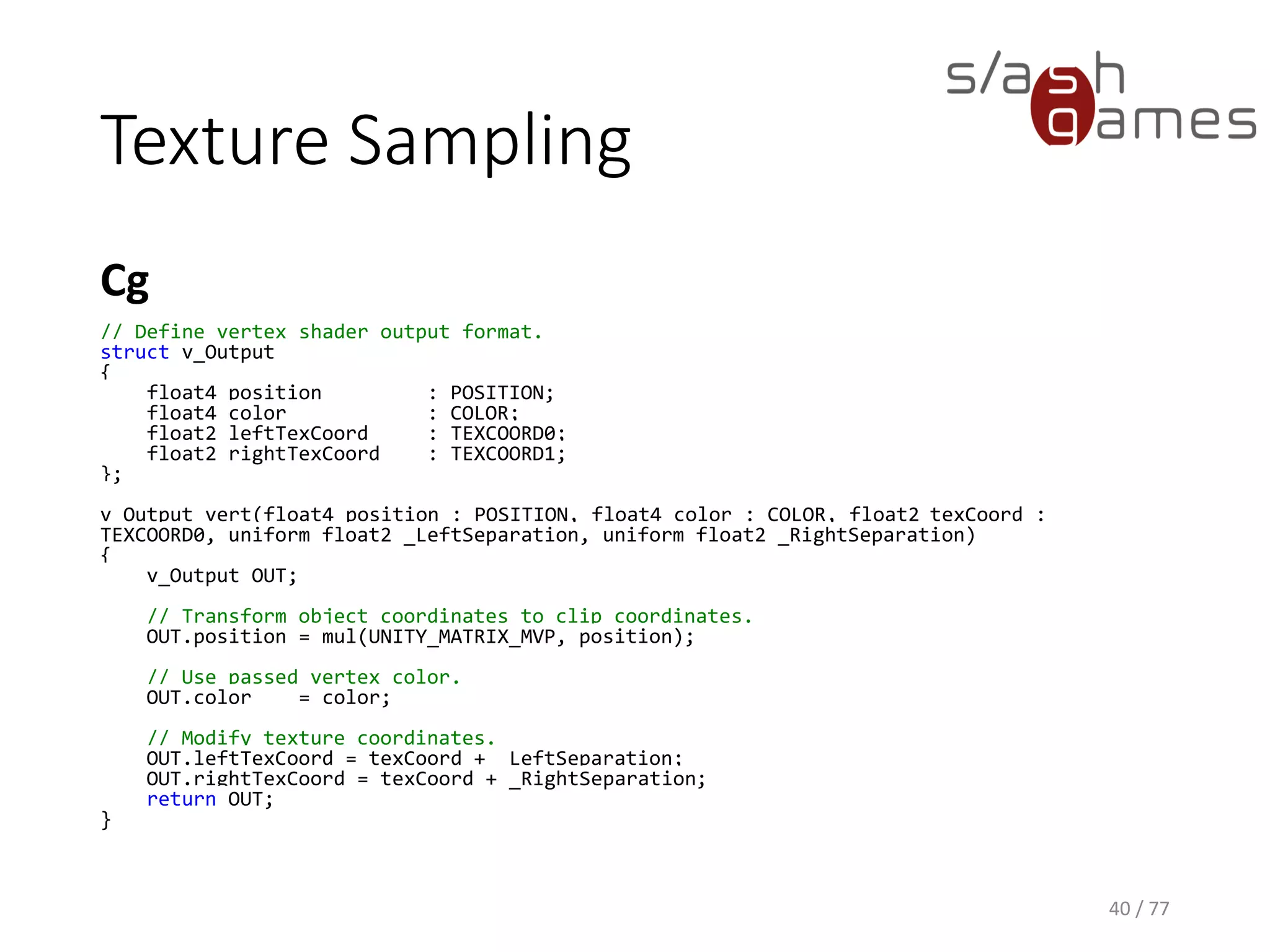
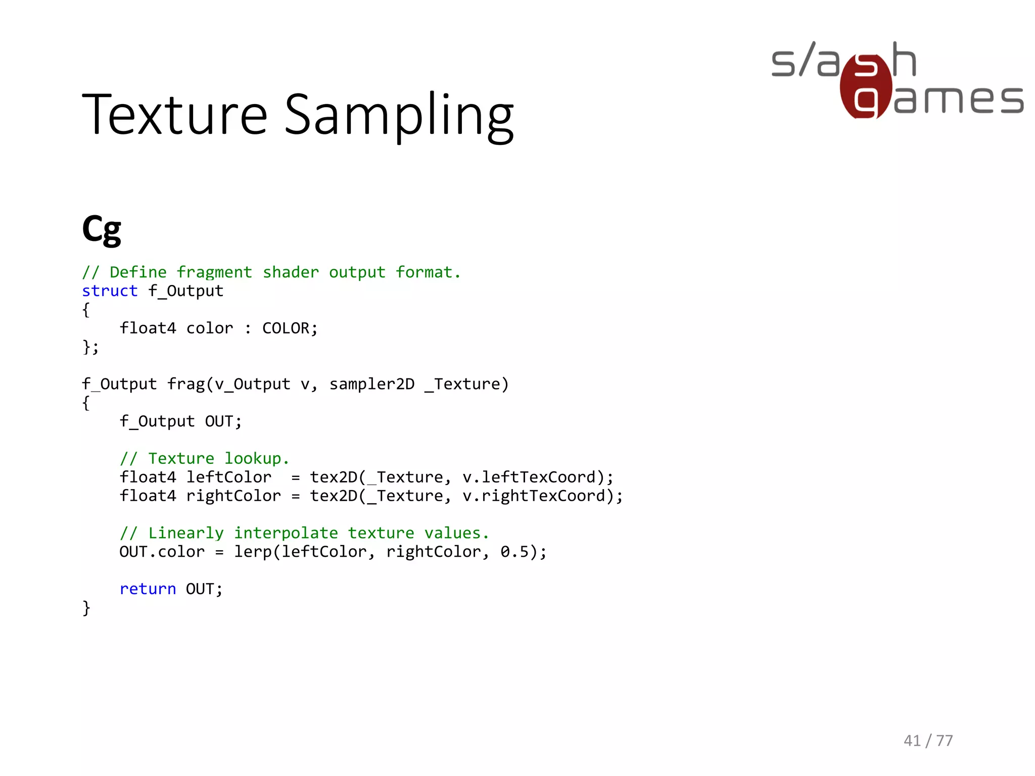

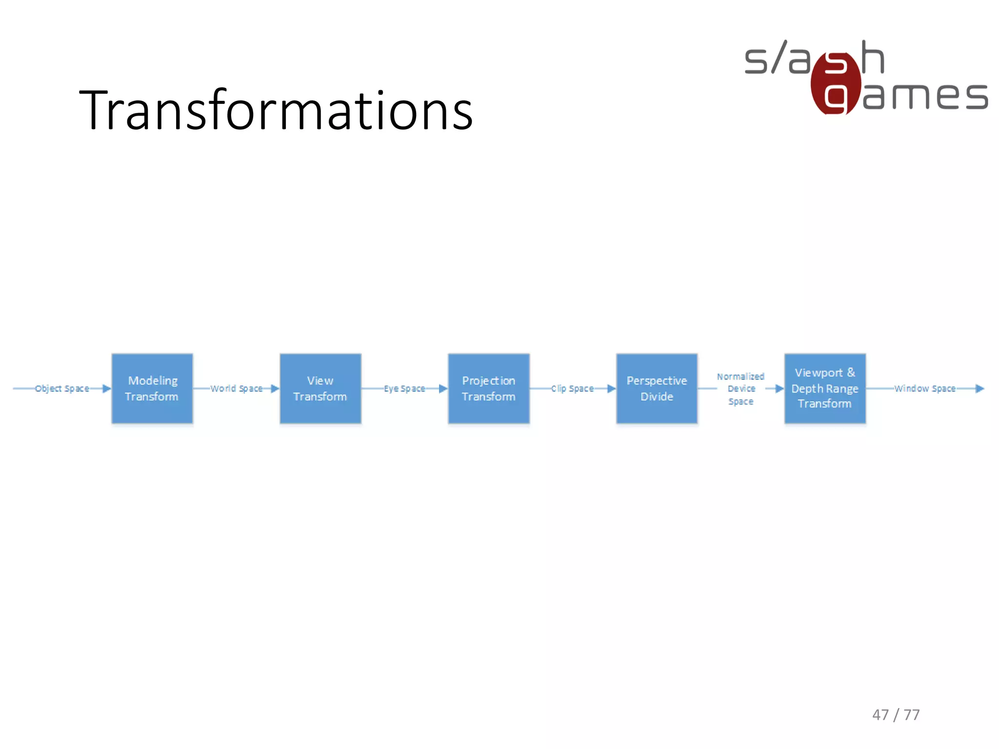


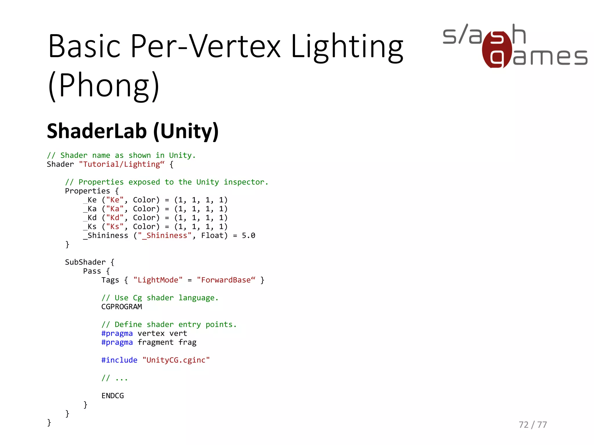
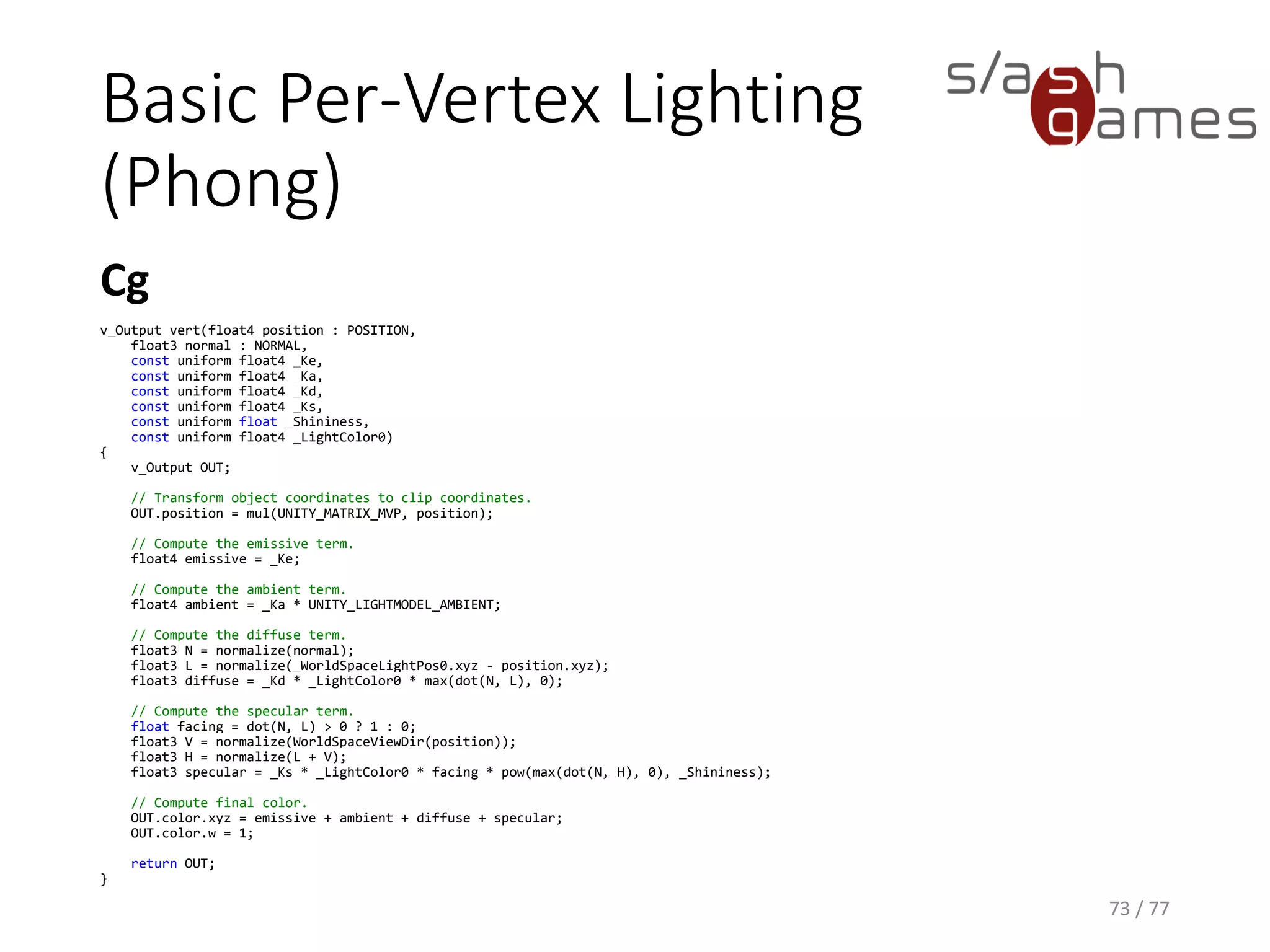
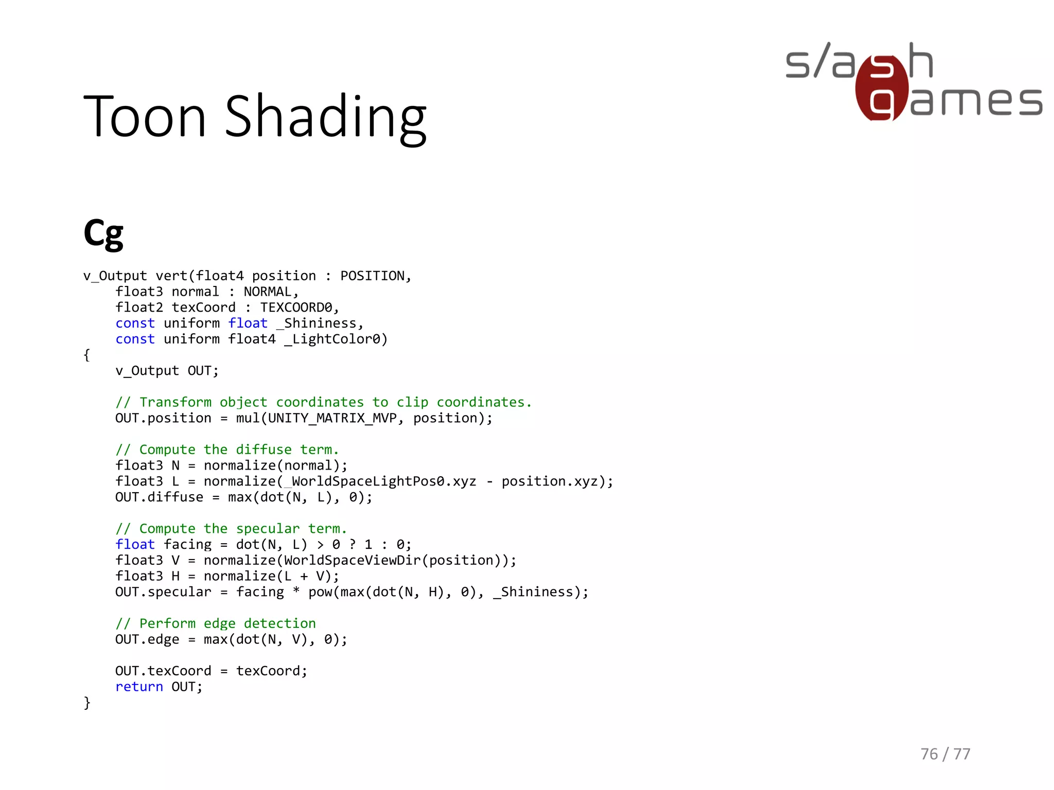
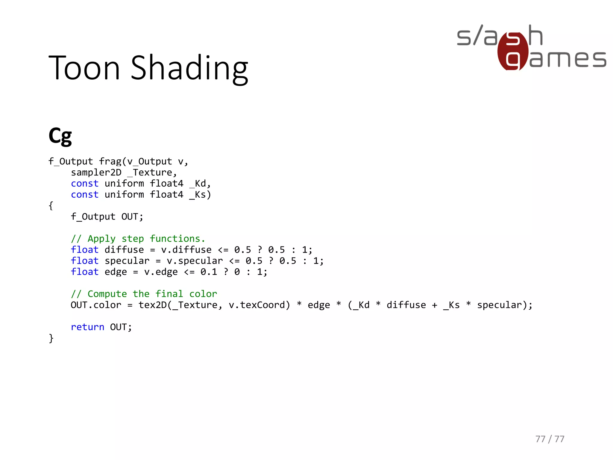
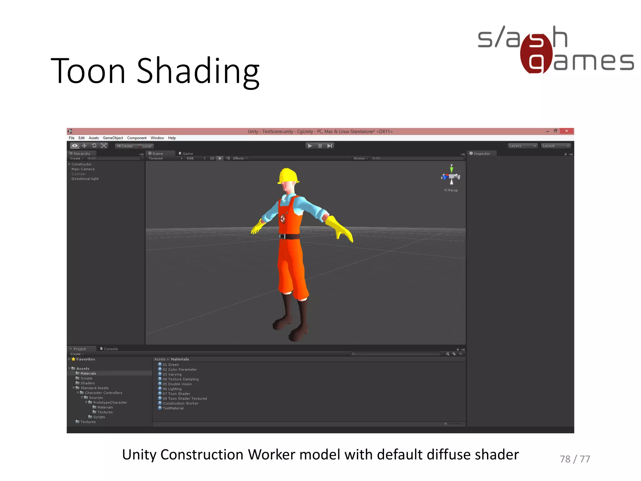
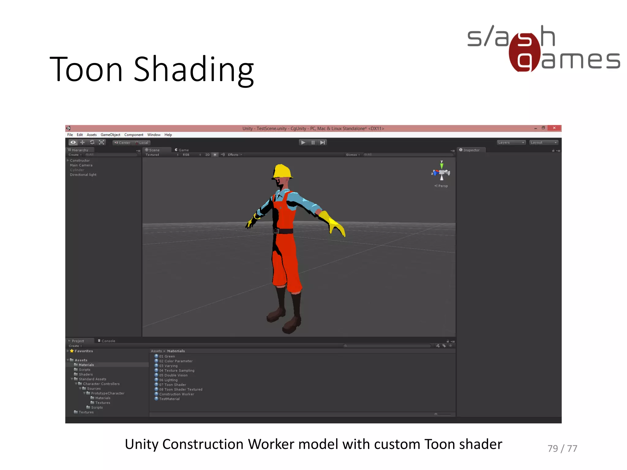


The document outlines the essential aspects of shader development and the graphics pipeline in modern GPUs. It covers key topics like CPU versus GPU performance, shader languages, and the stages of the graphics pipeline including vertex transformation, rasterization, and fragment processing. Additionally, it discusses lighting models and provides practical shader programming examples using Cg in Unity.


![[NDC17] 물리 기반 대기와 구름 만들기](https://cdn.slidesharecdn.com/ss_thumbnails/i2tcvqcbqsqf61glxqlq-signature-55756bd64a35cb3246b96d60a9e2797a447c2cb766454960d564aaadb5b23d96-poli-170524053948-thumbnail.jpg?width=600ounds&width=560&fit=bounds)

![[Kgc2012] deferred forward 이창희](https://cdn.slidesharecdn.com/ss_thumbnails/kgc2012deferredforward-121010214035-phpapp02-thumbnail.jpg?width=600ounds&width=560&fit=bounds)


![UiPath Automation Suite Installation (Hands-On) [2/3]](https://cdn.slidesharecdn.com/ss_thumbnails/automationsuitecommunitysession2-251015095633-a6d862f1-thumbnail.jpg?width=600ounds&width=560&fit=bounds)


