Download as PDF, PPTX


The document explains image segmentation in ERDAS Imagine, detailing the methods for partitioning raster images based on pixel values and locations. It covers parameters like edge detection, segmentation settings, and the use of spectral, texture, size, and shape weights in FLS segmentation. Additionally, it provides examples and exercises illustrating the segmentation process and its outcomes.
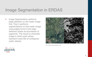
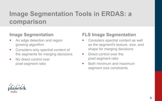
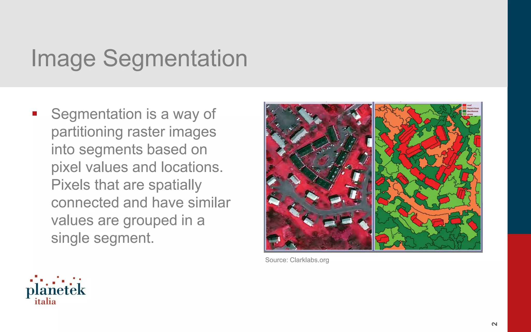
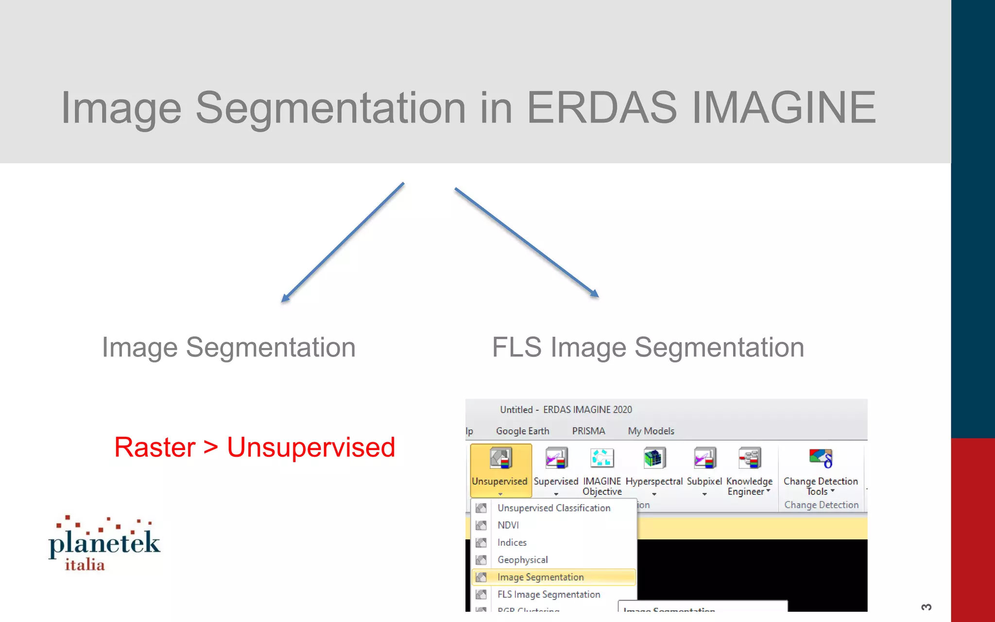
Overview of image segmentation methods used in ERDAS IMAGINE, emphasizing pixel grouping based on values.
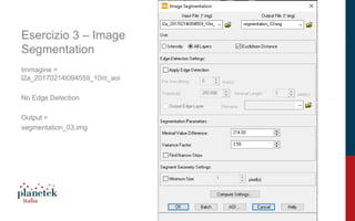
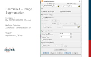
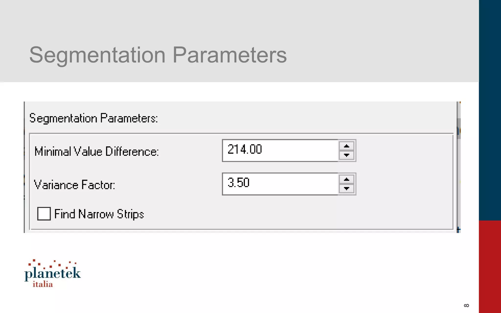
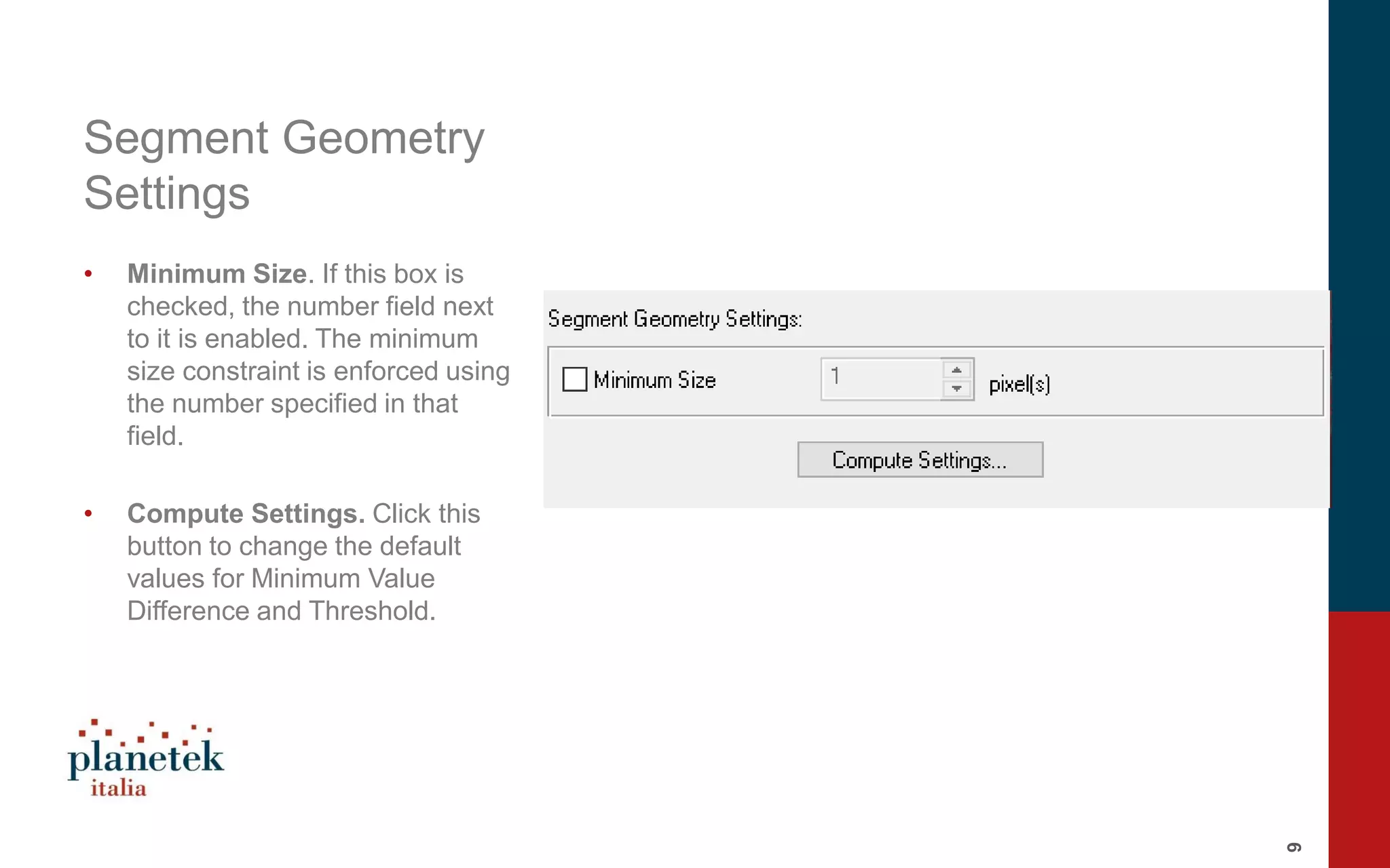
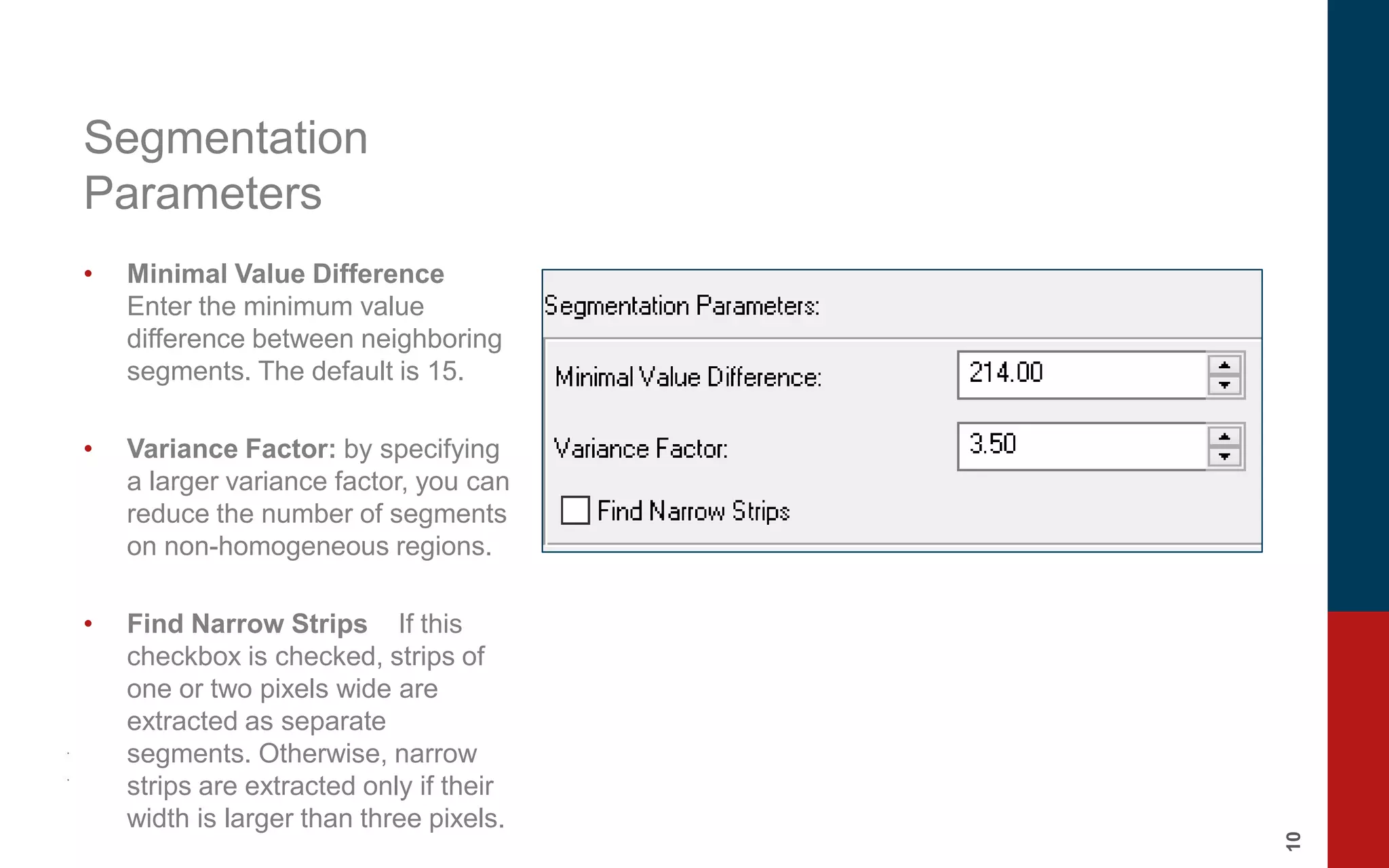
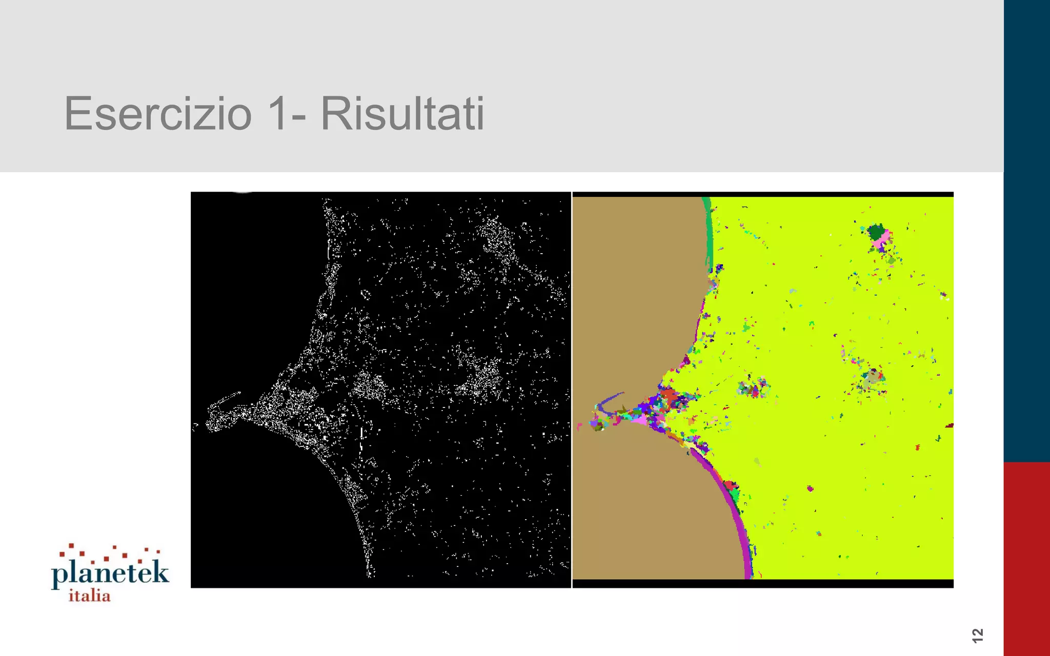
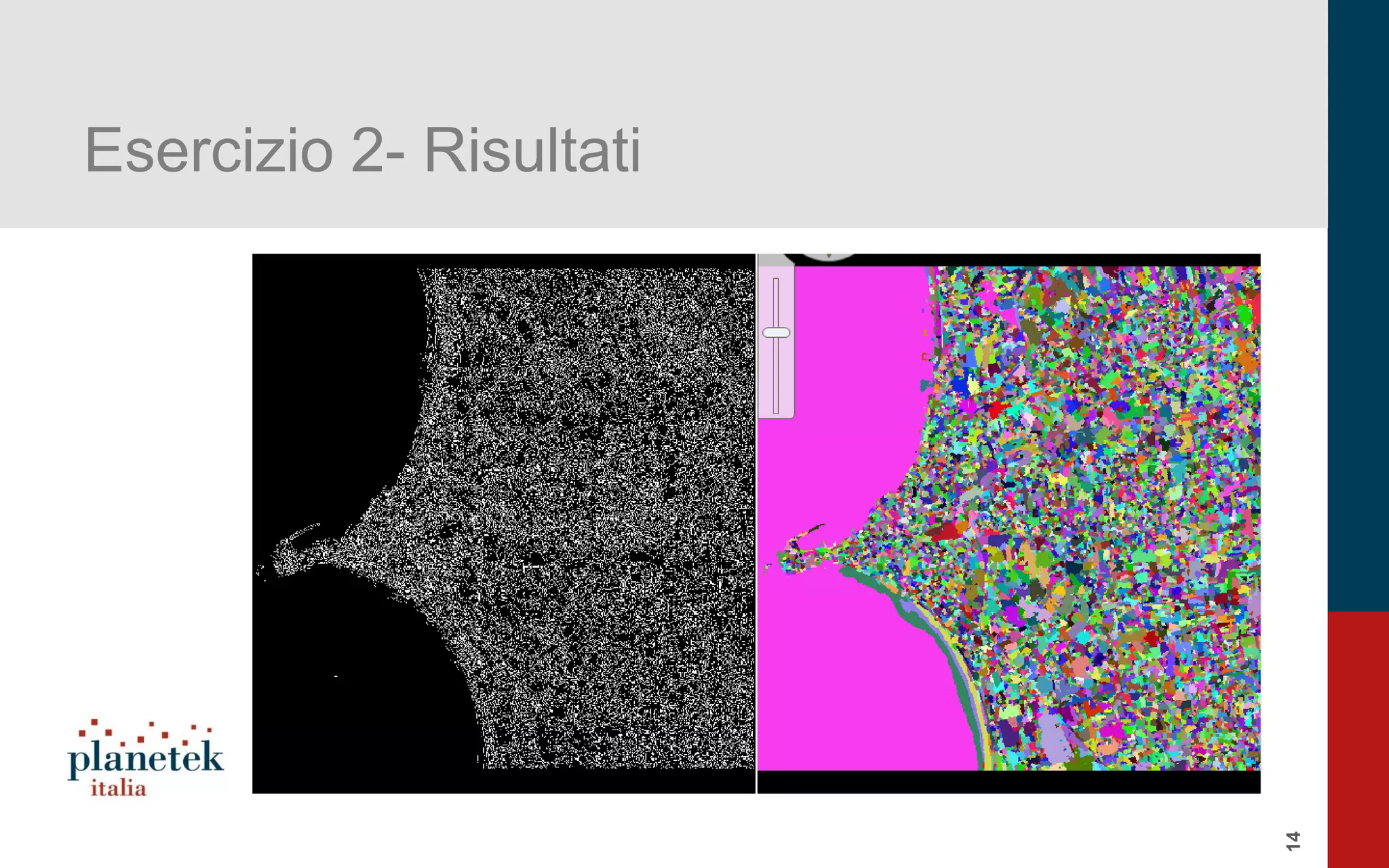
Details on image segmentation in ERDAS IMAGINE including edge detection and the creation of thematic images.
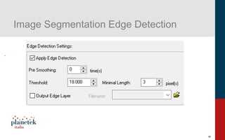
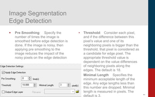
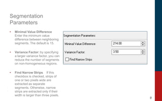
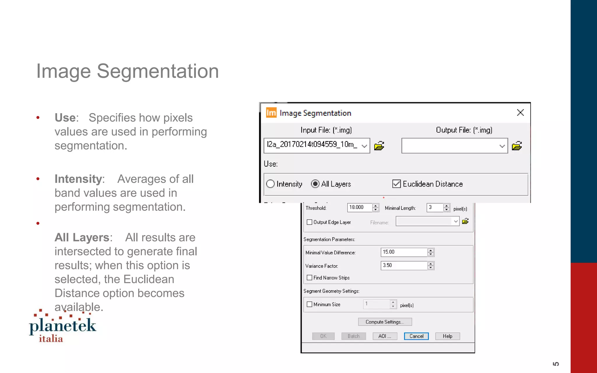
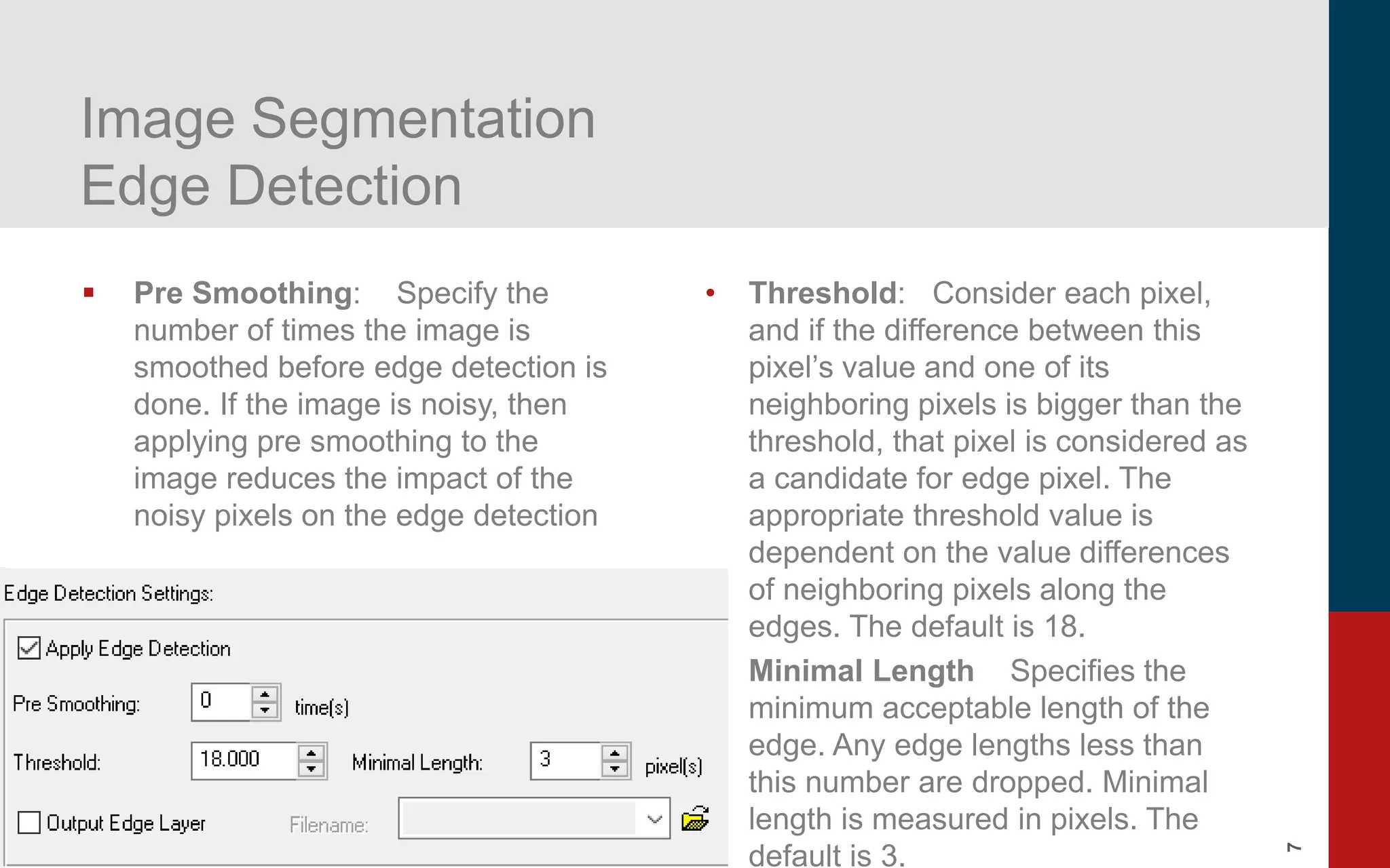
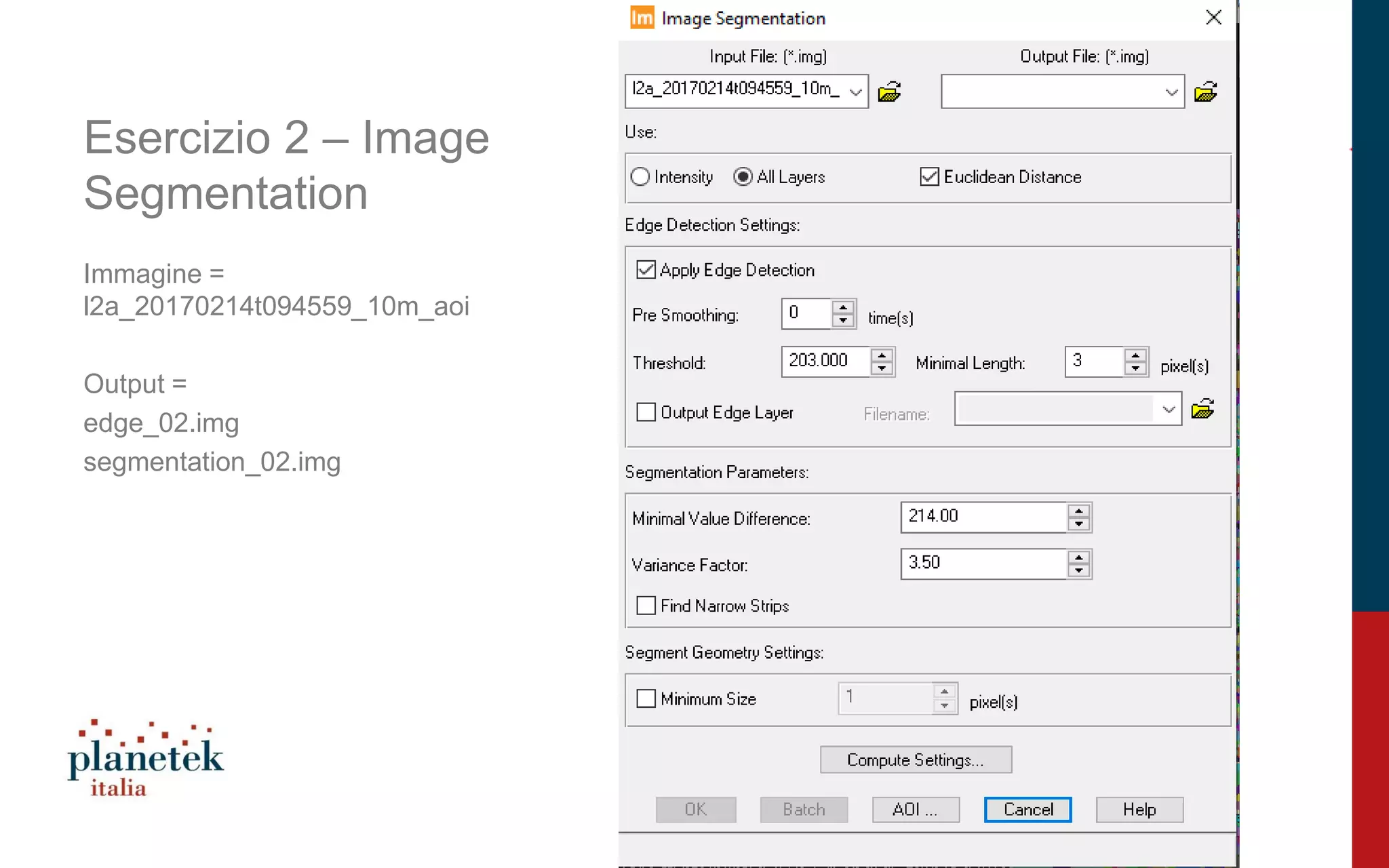
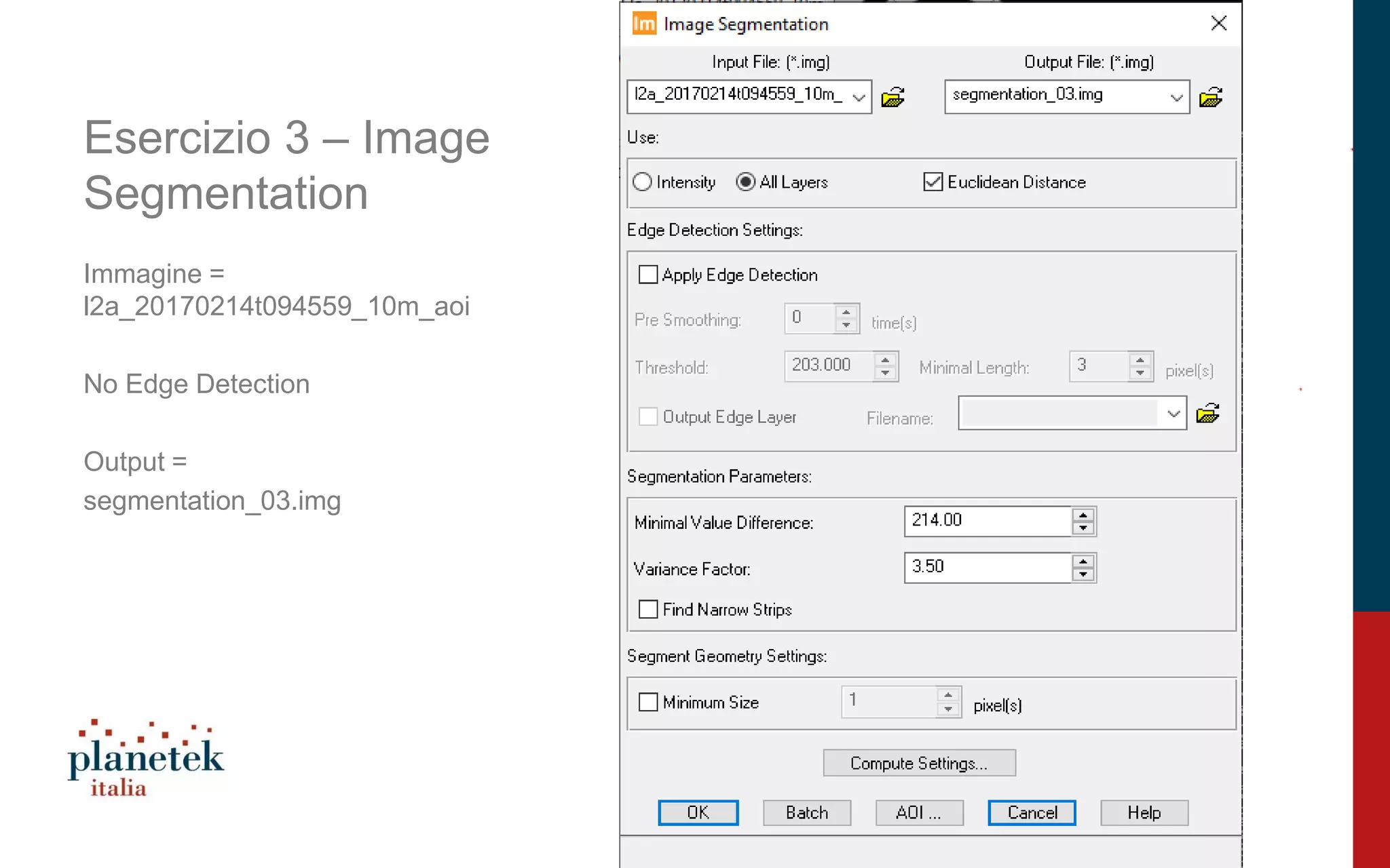
Explores methods and settings including intensity, primary parameters, and edge detection specifics in image segmentation.
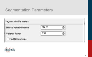
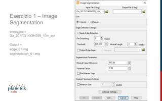
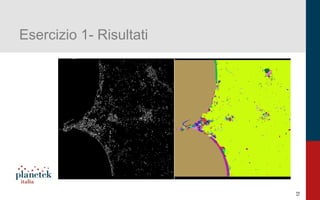
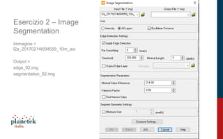
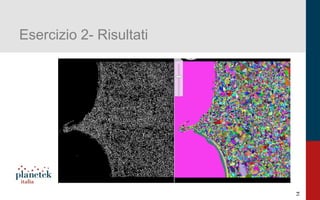
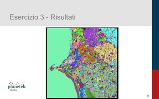
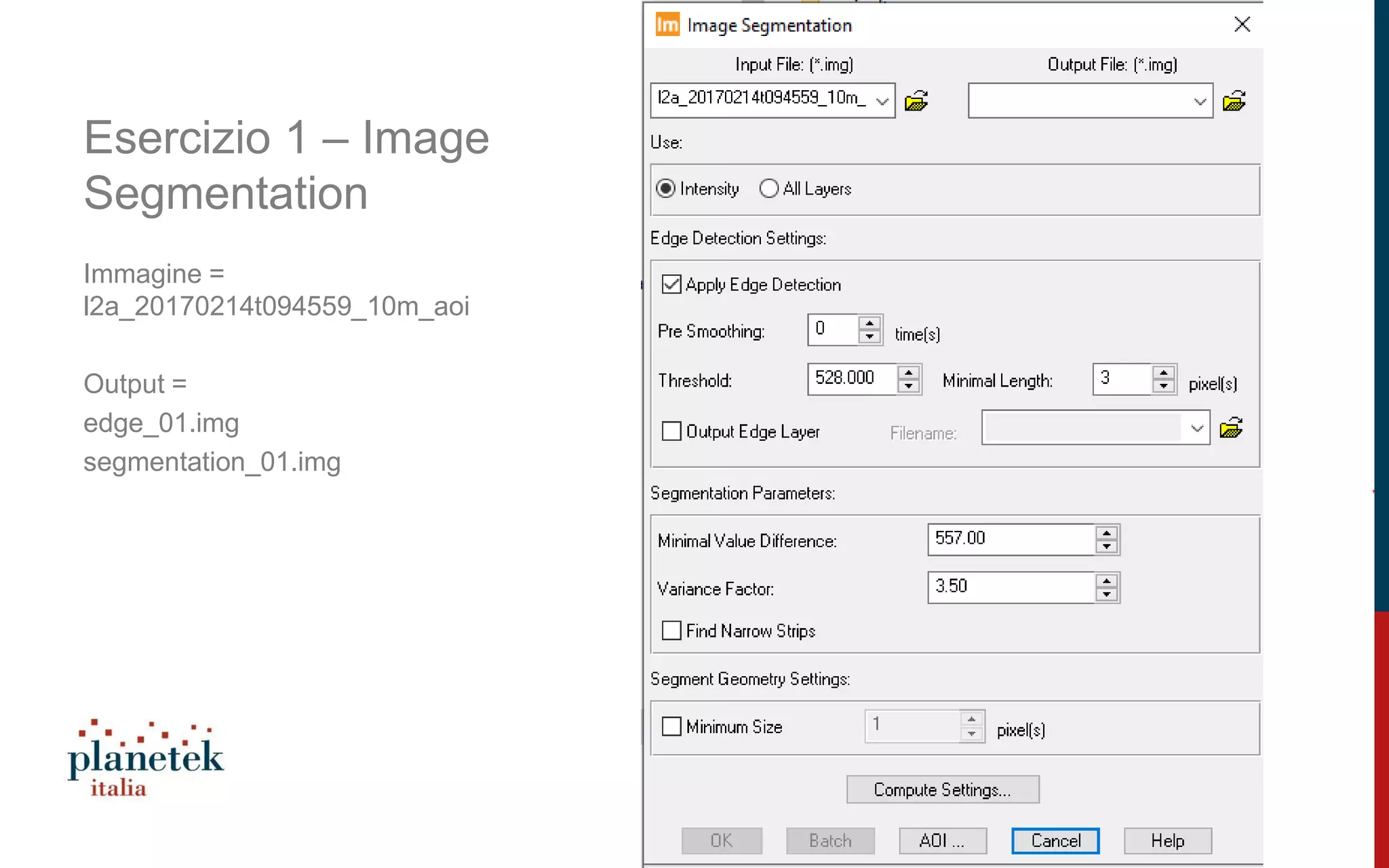
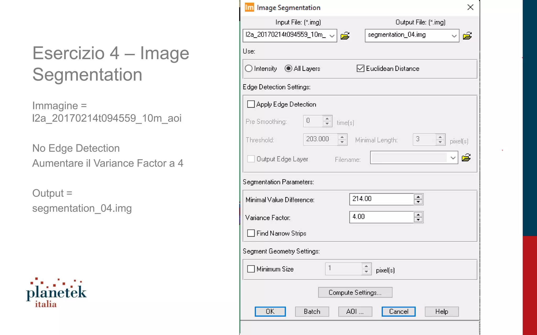
Exercises showcasing image segmentation with specific outputs and adjustments for edge detection and variance factors.
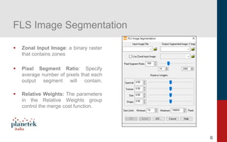
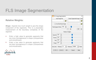
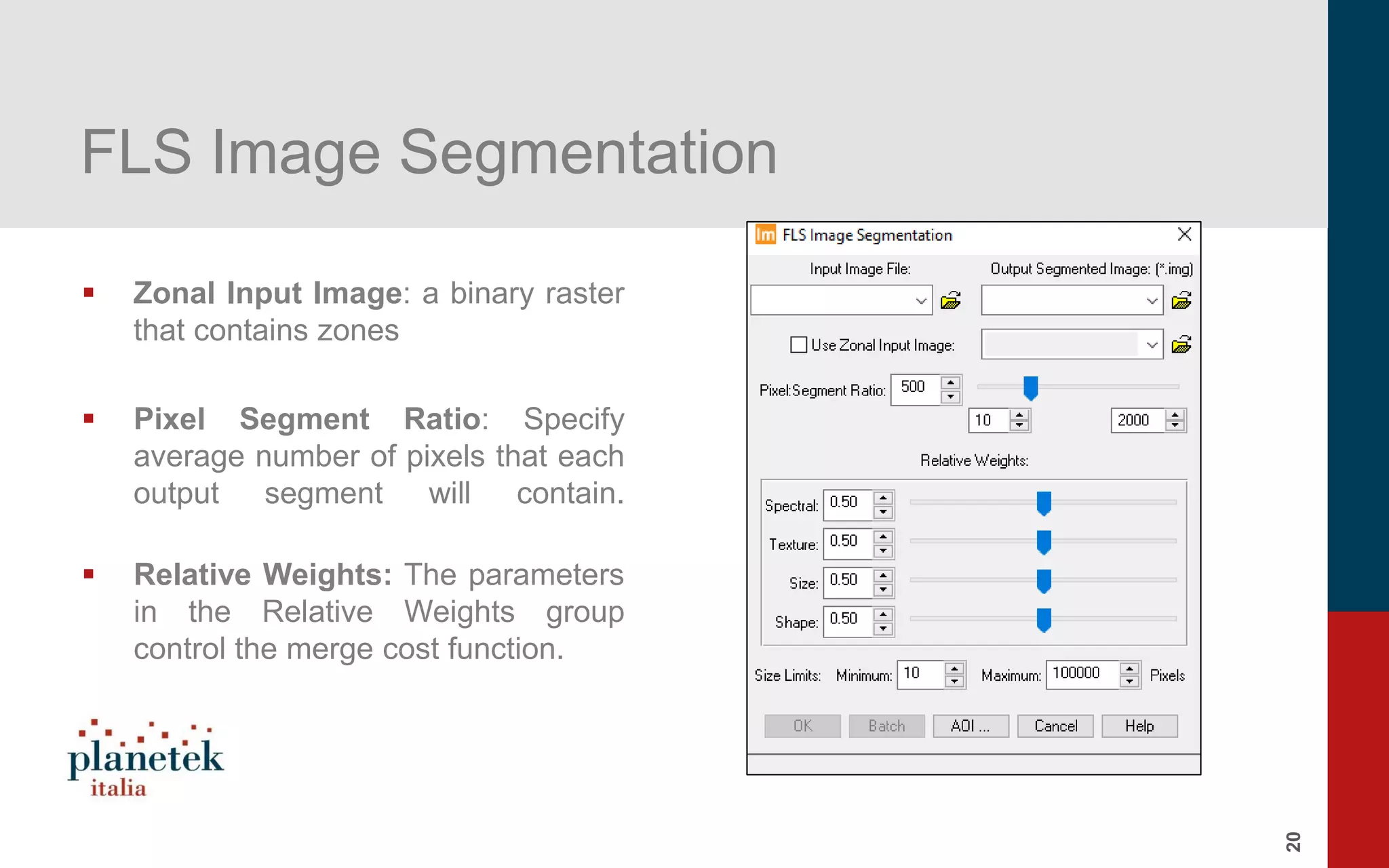
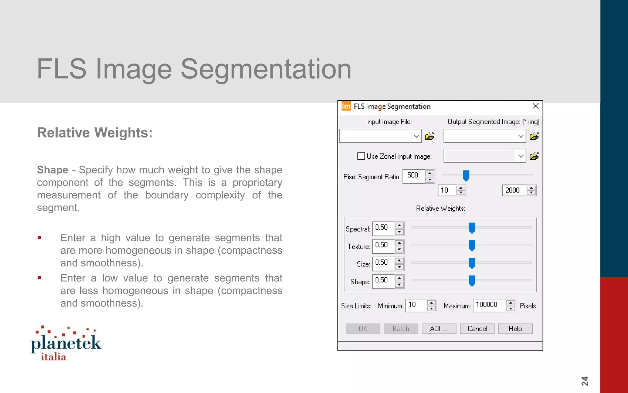
Introduction to FLS image segmentation, including its parameters for zonal inputs and pixel segment ratios.
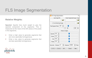
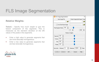
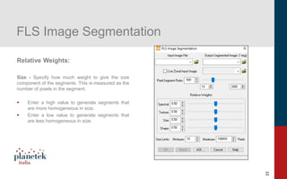
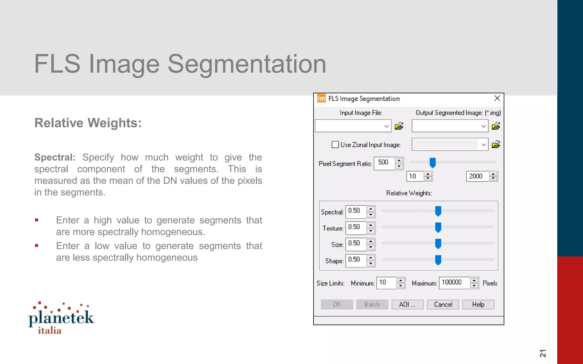
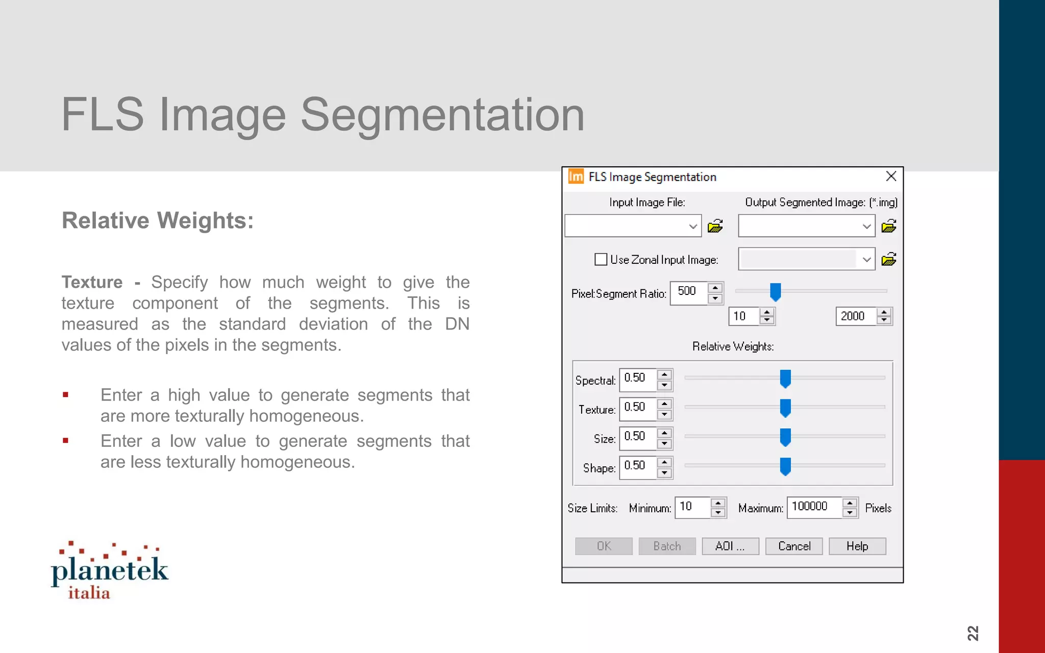
Parameters affecting segment characteristics such as spectral, texture, size, and shape in FLS image segmentation.
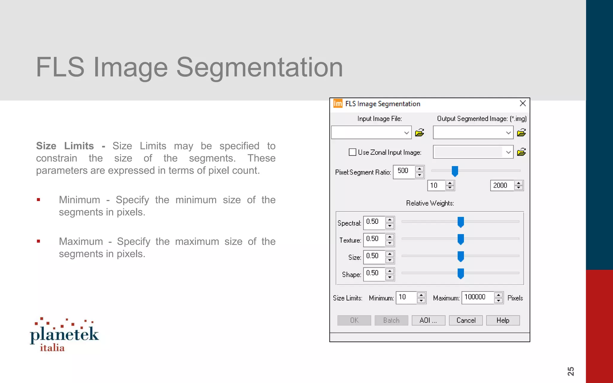
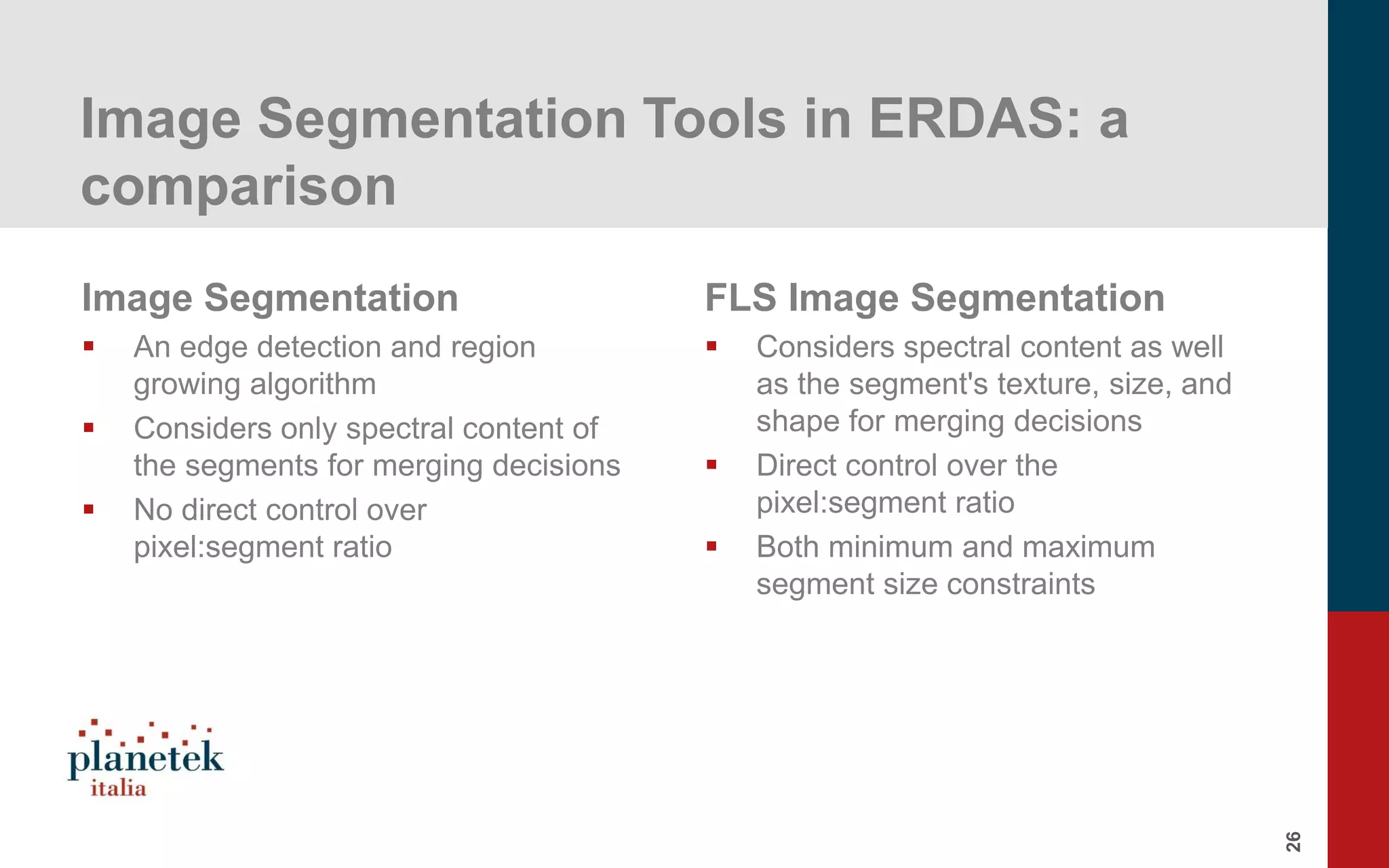
Details on size limits in segments for FLS segmentation, comparing image segmentation techniques based on spectral and spatial factors.
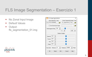
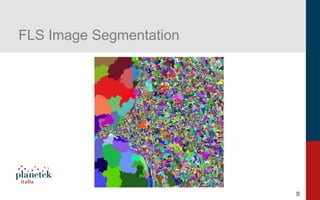
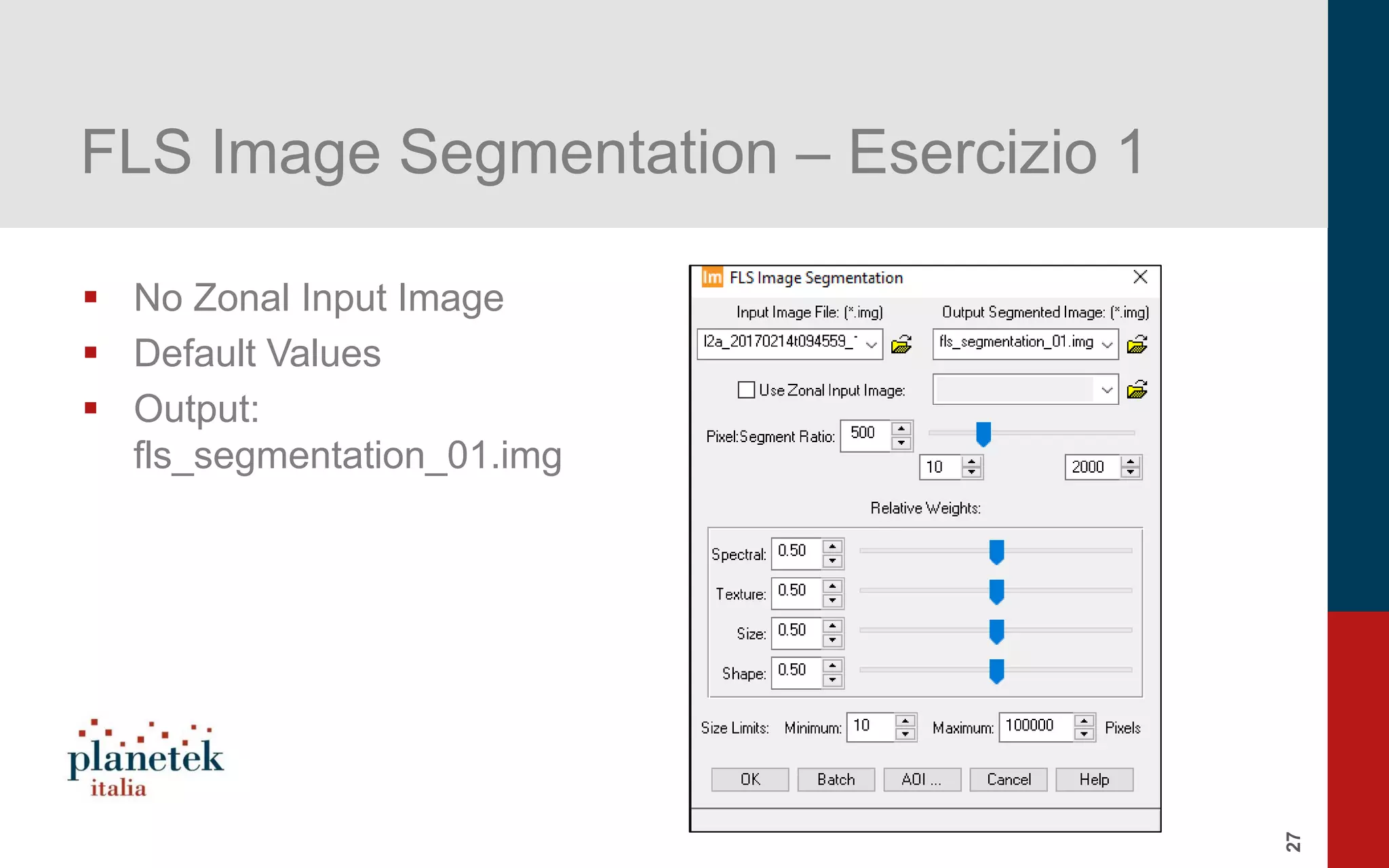
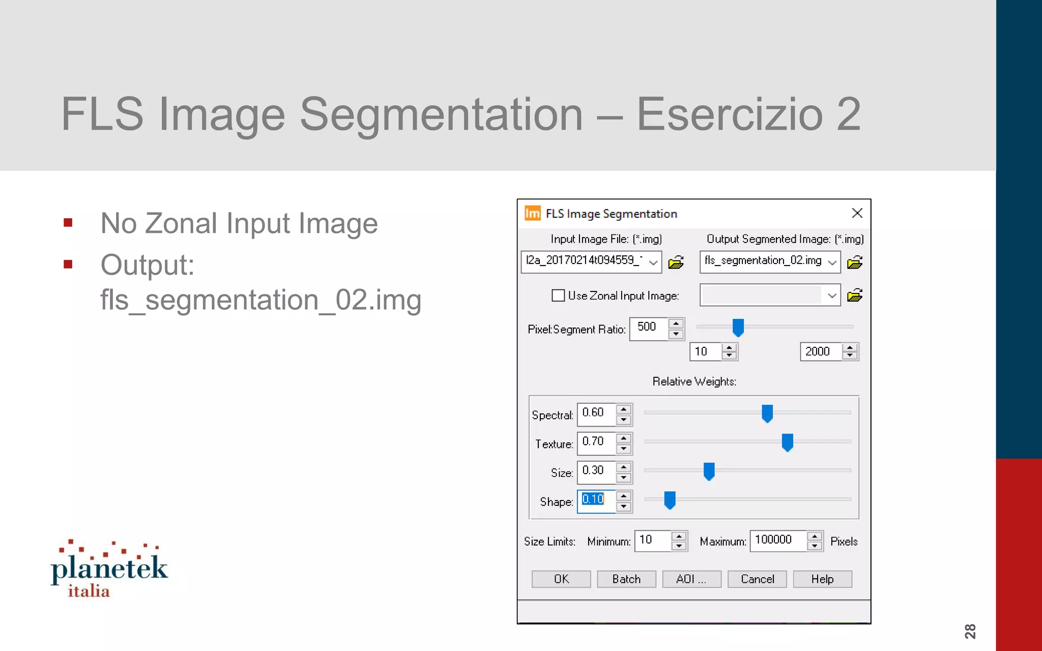
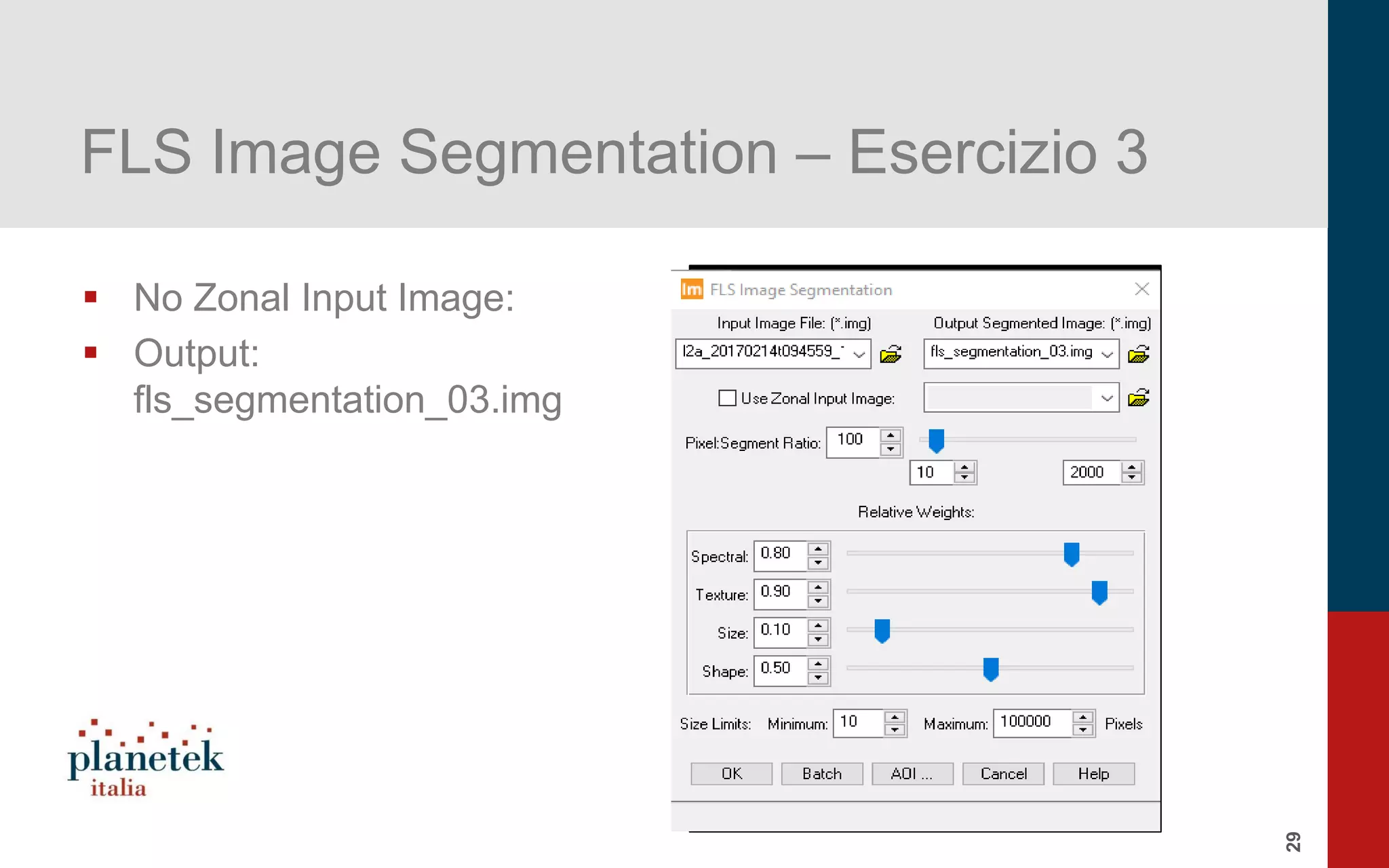
Practical exercises demonstrating FLS image segmentation without zonal input images and resulting outputs.
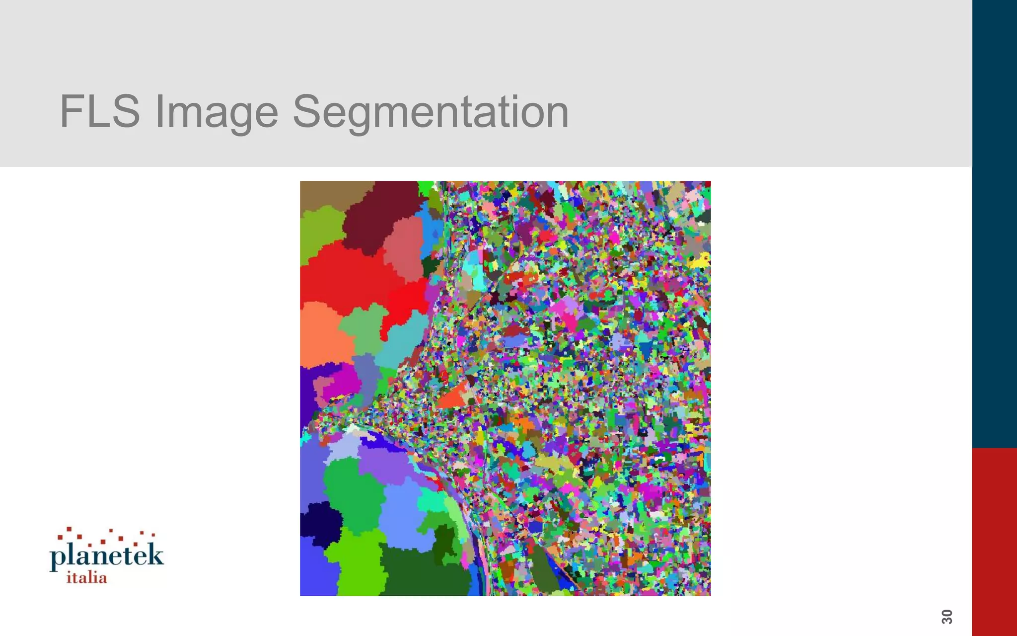
Final overview and wrap-up of image segmentation techniques discussed throughout the presentation.


![[Webinar] Il telerilevamento da droni aerei: Le soluzioni Hexagon Geospatial ...](https://cdn.slidesharecdn.com/ss_thumbnails/pkm026-594-1-150128104853-conversion-gate01-thumbnail.jpg?width=600ounds&width=560&fit=bounds)
![[Webinar] Il telerilevamento da droni aerei: I sensori PANOPTES nelle ispezio...](https://cdn.slidesharecdn.com/ss_thumbnails/webinardronidargeniopanoptes021214-150128102053-conversion-gate02-thumbnail.jpg?width=600ounds&width=560&fit=bounds)
![[Webinar] Il telerilevamento da droni aerei: soluzioni Leica Geosystems e cas...](https://cdn.slidesharecdn.com/ss_thumbnails/webinardronileicageosystems12015mlmod-150128101516-conversion-gate02-thumbnail.jpg?width=600ounds&width=560&fit=bounds)
![[Webinar] Il telerilevamento da droni aerei: La normativa italiana ENAC e il ...](https://cdn.slidesharecdn.com/ss_thumbnails/webinardroniassorpaspresentazione27gennaio2015-150128100431-conversion-gate01-thumbnail.jpg?width=600ounds&width=560&fit=bounds)


![RTP_AR_Basic_Learners' Workbook_KS2 [FOR REPRODUCTION] (1).pdf](https://cdn.slidesharecdn.com/ss_thumbnails/rtparbasiclearnersworkbookks2forreproduction1-251016024943-e51a16ac-thumbnail.jpg?width=600ounds&width=560&fit=bounds)