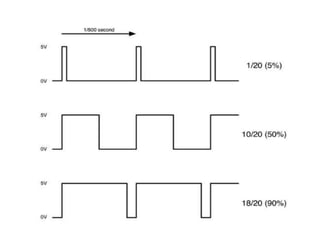
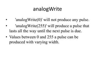
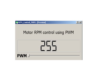
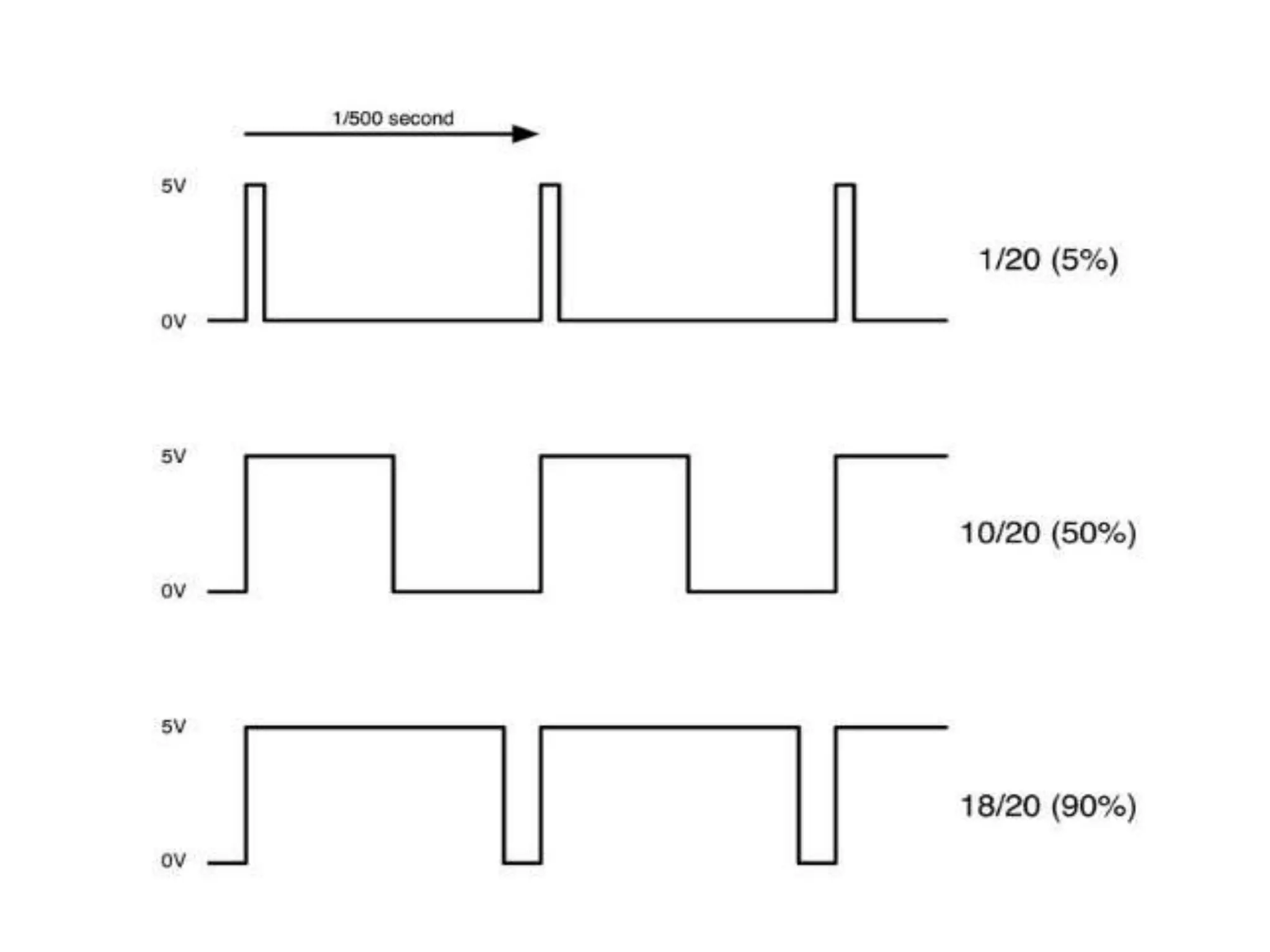
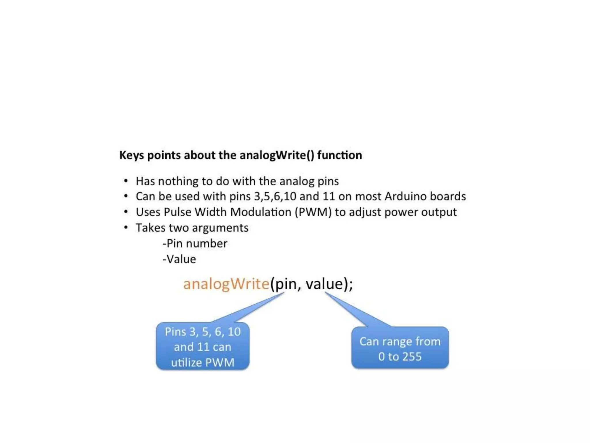
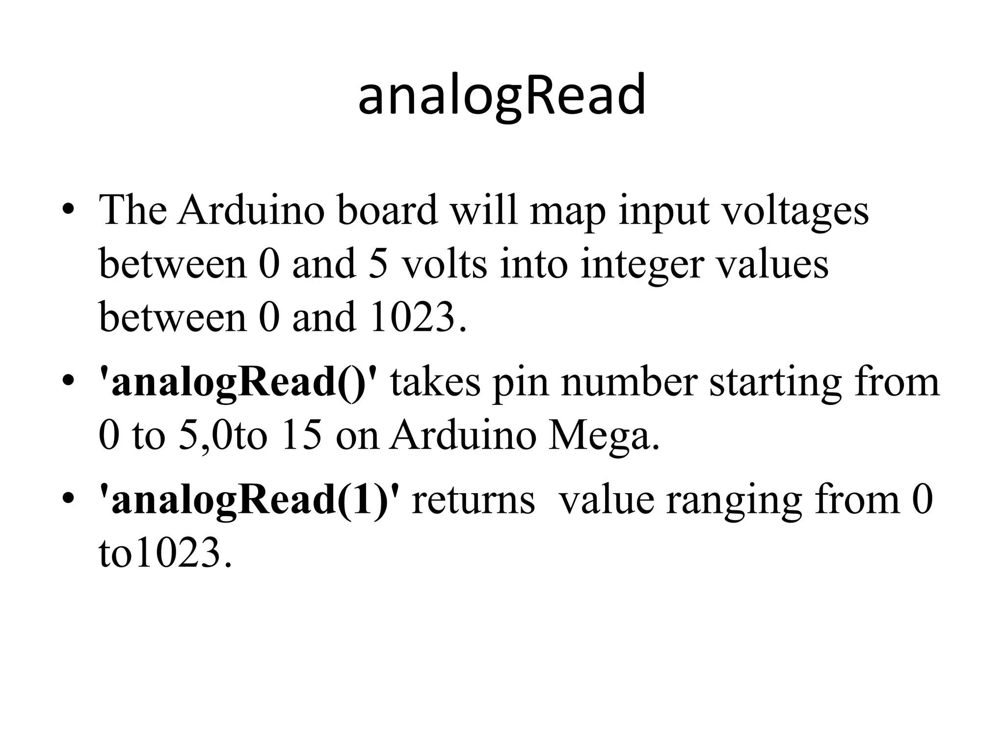
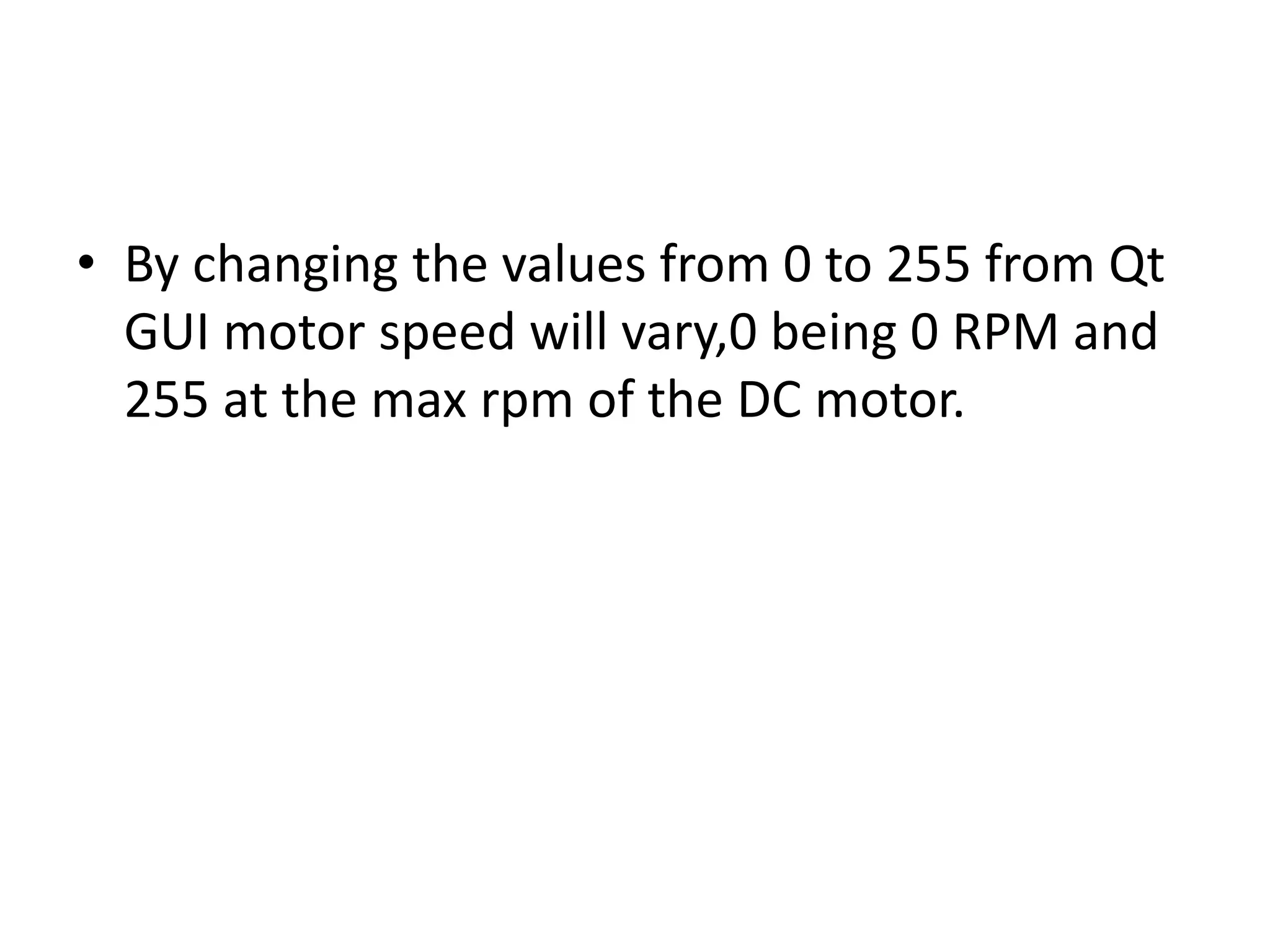
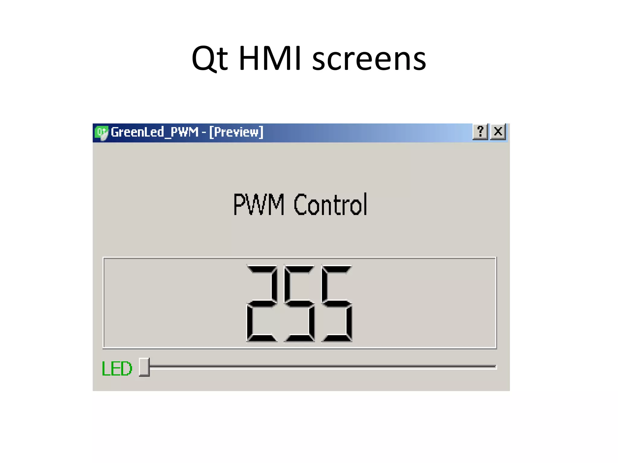
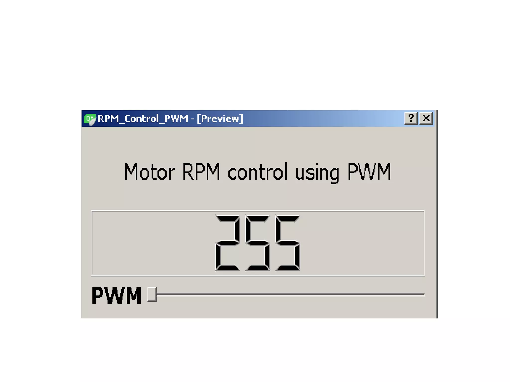
KEMBAR78
Qt arduino serial_port | PPTX
Arduino Qt HMI - Serial Port
A Term Paper Final Report
by
SATYENDRA KUMAR J
M. Tech. (Mechatronics) 1st semester Student
Under the supervision of
T ESHWAR RAO
ASSOCIATE PROFESSOR
DEPARTMENT OF MECHANICAL ENGINEERING
K L University, Green Fields,
Vaddeswaram- 522502, Guntur(Dist), Andhra Pradesh, India.
April - 2017
contents
• Abstract
• Introduction
• Required Setup
• Methodology
• Theory(PWM)
• analogWrite()
• Observation
• analogRead()
• Qt HMI Screens.
• References
Abstract
• To create customized Qt graphical user
interfaces (GUI), which facilitates brightness
control of LED, and RPM display of DC
Motor,connected to an Arduino Uno
Microcontroller.
Introduction
• By using the Qt's serial port functionality in
conjunction with an Arduino uno
Microcontroller (RS232 device) ,it is possible
to control the color brightness of an LED.
• similarly change the speed of a DC motor by
sending the values from a Qt GUI in a range of
0 to 255 and display the RPM of motor on the
same GUI.
• Serial commands can be sent from GUI (Qt)
and the same way parsing them on Arduino (at
a baud rate of 9600),communication will be
established with the Qt GUI and there to the
LED or DC Motor connected to Arduino
Microcontroller by jumper wires on a
breadboard.
Required Setup
• Install Qt 5.7.1.
• Serial Port Library installed on the Host
machine. (Windows/Ubuntu).
• Qt C++ based GUI screen for sending PWM
values (0 to 255).
• Resistors(300 Ω upto 1KΩ), (red, purple,
brown stripes)
• LEDs (Red, Green, Blue colors).
• DC Motor.(0to 5Volts),1000RPM.
• Jumper wire pack (M to M)
• BreadBoard
Methodology
• It is possible to control the brightness intensity
of the Red, Green, Blue lights (RGB LED)on
the Breadboard by writing code in Qt C++, and
sending commands from Qt GUI to the
Arduino microcontroller.
• So whenever there is a change in the value on
the GUI control present on the computer, the
corresponding value is sent to Arduino
microcontroller.
Pulse Width Modulation
• Pulse Width Modulation( PWM), is a
technique for getting analog results with digital
means, the on-off pattern can simulate voltages
in between full on (5 Volts) and off (0 Volts)
by changing the portion of the time the signal
spends on to off.
• The duration of "on time" is called the pulse
width.
• There are 5 pins on most Arduino boards
marked with "~" next to the pin number (on
some boards it is an “PWM” symbol).
• Pulse Width Modulation (or PWM) is a
technique for controlling power.In this case it
is used to control the brightness of LEDs.
• Roughly every 1/500 of a second, the PWM
output will produce a pulse. The length of this
pulse is controlled by the 'analogWrite'
function.
• By specifying a value in the analogWrite(val),
function between 0 and 255 a pulse can be
produced.
• If the output pulse is only high for 5% of the
time then whatever is driven will only receive
5% of full power.
• Similarly if the output pulse is high for 95% of
the time then whatever is driven will receive
95% of full power. (in this case an LED and DC
Motor).
• SIGNALS from one of the PWM pins on
Arduino Uno Microcontroller at different
voltages and duty cycles.
• Voltages (0V to 5V)
• Duty cycles samples (5%),(50%),and(90%).
• To get varying analog values, change, or
modulate, the pulse width.
• If this on-off pattern is repeated fast enough on
Arduino,with an LED,the result is as if the
signal is a steady voltage between 0 and 5v
controlling the brightness of the LED.
analogWrite
• 'analogWrite(0)' will not produce any pulse.
• 'analogWrite(255)' will produce a pulse that
lasts all the way until the next pulse is due.
• Values between 0 and 255 a pulse can be
produced with varying width.
analogRead
• The Arduino board will map input voltages
between 0 and 5 volts into integer values
between 0 and 1023.
• 'analogRead()' takes pin number starting from
0 to 5,0to 15 on Arduino Mega.
• 'analogRead(1)' returns value ranging from 0
to1023.
• By changing the values from 0 to 255 from Qt
GUI motor speed will vary,0 being 0 RPM and
255 at the max rpm of the DC motor.
Qt HMI screens
References
• Modeling and Simulation of Pulse-Width
Modulation Inverter
• GAI Zhi-wu 1,LI Dong-sheng 1 ,SONG Zhe-cun 1 ,MA Yong 2,YU Ji-lai 2 (1.Electromechanical
Engineering College of Northeast Forestry University,Harbin Heilongjiang 150040,China; 2.HarBin
Institute of Technology,Harbin Heilongjiang 150001,Chi
• Simulation Research of Switching Power
Supply Based on PWM
• WANG Bing,ZHANG Runhe,SUN Yanxia (Information Engineering College,Inner Mongolia
University of Technology,Hohhot,010051,China)
• https://forum.arduino.cc
• https://forum.qt.io

Qt arduino serial_port

  • 1.
    Arduino Qt HMI- Serial Port A Term Paper Final Report by SATYENDRA KUMAR J M. Tech. (Mechatronics) 1st semester Student Under the supervision of T ESHWAR RAO ASSOCIATE PROFESSOR DEPARTMENT OF MECHANICAL ENGINEERING K L University, Green Fields, Vaddeswaram- 522502, Guntur(Dist), Andhra Pradesh, India. April - 2017
  • 2.
    contents • Abstract • Introduction •Required Setup • Methodology • Theory(PWM) • analogWrite() • Observation • analogRead() • Qt HMI Screens. • References
  • 3.
    Abstract • To createcustomized Qt graphical user interfaces (GUI), which facilitates brightness control of LED, and RPM display of DC Motor,connected to an Arduino Uno Microcontroller.
  • 4.
    Introduction • By usingthe Qt's serial port functionality in conjunction with an Arduino uno Microcontroller (RS232 device) ,it is possible to control the color brightness of an LED. • similarly change the speed of a DC motor by sending the values from a Qt GUI in a range of 0 to 255 and display the RPM of motor on the same GUI.
  • 5.
    • Serial commandscan be sent from GUI (Qt) and the same way parsing them on Arduino (at a baud rate of 9600),communication will be established with the Qt GUI and there to the LED or DC Motor connected to Arduino Microcontroller by jumper wires on a breadboard.
  • 6.
    Required Setup • InstallQt 5.7.1. • Serial Port Library installed on the Host machine. (Windows/Ubuntu). • Qt C++ based GUI screen for sending PWM values (0 to 255). • Resistors(300 Ω upto 1KΩ), (red, purple, brown stripes) • LEDs (Red, Green, Blue colors). • DC Motor.(0to 5Volts),1000RPM.
  • 7.
    • Jumper wirepack (M to M) • BreadBoard
  • 8.
    Methodology • It ispossible to control the brightness intensity of the Red, Green, Blue lights (RGB LED)on the Breadboard by writing code in Qt C++, and sending commands from Qt GUI to the Arduino microcontroller. • So whenever there is a change in the value on the GUI control present on the computer, the corresponding value is sent to Arduino microcontroller.
  • 9.
    Pulse Width Modulation •Pulse Width Modulation( PWM), is a technique for getting analog results with digital means, the on-off pattern can simulate voltages in between full on (5 Volts) and off (0 Volts) by changing the portion of the time the signal spends on to off. • The duration of "on time" is called the pulse width.
  • 10.
    • There are5 pins on most Arduino boards marked with "~" next to the pin number (on some boards it is an “PWM” symbol). • Pulse Width Modulation (or PWM) is a technique for controlling power.In this case it is used to control the brightness of LEDs.
  • 11.
    • Roughly every1/500 of a second, the PWM output will produce a pulse. The length of this pulse is controlled by the 'analogWrite' function. • By specifying a value in the analogWrite(val), function between 0 and 255 a pulse can be produced.
  • 12.
    • If theoutput pulse is only high for 5% of the time then whatever is driven will only receive 5% of full power. • Similarly if the output pulse is high for 95% of the time then whatever is driven will receive 95% of full power. (in this case an LED and DC Motor).
  • 14.
    • SIGNALS fromone of the PWM pins on Arduino Uno Microcontroller at different voltages and duty cycles. • Voltages (0V to 5V) • Duty cycles samples (5%),(50%),and(90%).
  • 15.
    • To getvarying analog values, change, or modulate, the pulse width. • If this on-off pattern is repeated fast enough on Arduino,with an LED,the result is as if the signal is a steady voltage between 0 and 5v controlling the brightness of the LED.
  • 16.
    analogWrite • 'analogWrite(0)' willnot produce any pulse. • 'analogWrite(255)' will produce a pulse that lasts all the way until the next pulse is due. • Values between 0 and 255 a pulse can be produced with varying width.
  • 18.
    analogRead • The Arduinoboard will map input voltages between 0 and 5 volts into integer values between 0 and 1023. • 'analogRead()' takes pin number starting from 0 to 5,0to 15 on Arduino Mega. • 'analogRead(1)' returns value ranging from 0 to1023.
  • 19.
    • By changingthe values from 0 to 255 from Qt GUI motor speed will vary,0 being 0 RPM and 255 at the max rpm of the DC motor.
  • 20.
  • 22.
    References • Modeling andSimulation of Pulse-Width Modulation Inverter • GAI Zhi-wu 1,LI Dong-sheng 1 ,SONG Zhe-cun 1 ,MA Yong 2,YU Ji-lai 2 (1.Electromechanical Engineering College of Northeast Forestry University,Harbin Heilongjiang 150040,China; 2.HarBin Institute of Technology,Harbin Heilongjiang 150001,Chi • Simulation Research of Switching Power Supply Based on PWM • WANG Bing,ZHANG Runhe,SUN Yanxia (Information Engineering College,Inner Mongolia University of Technology,Hohhot,010051,China)
  • 23.