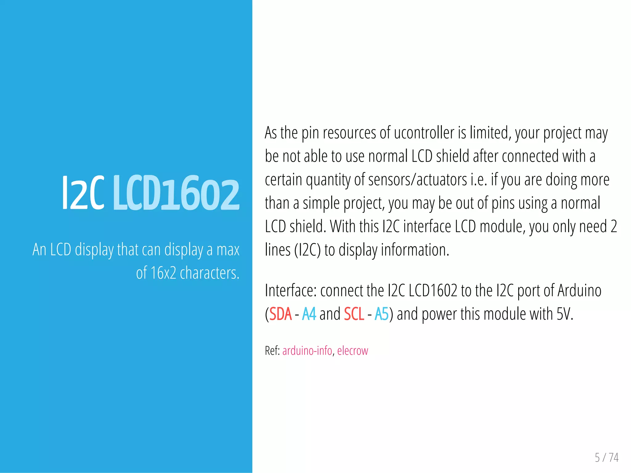
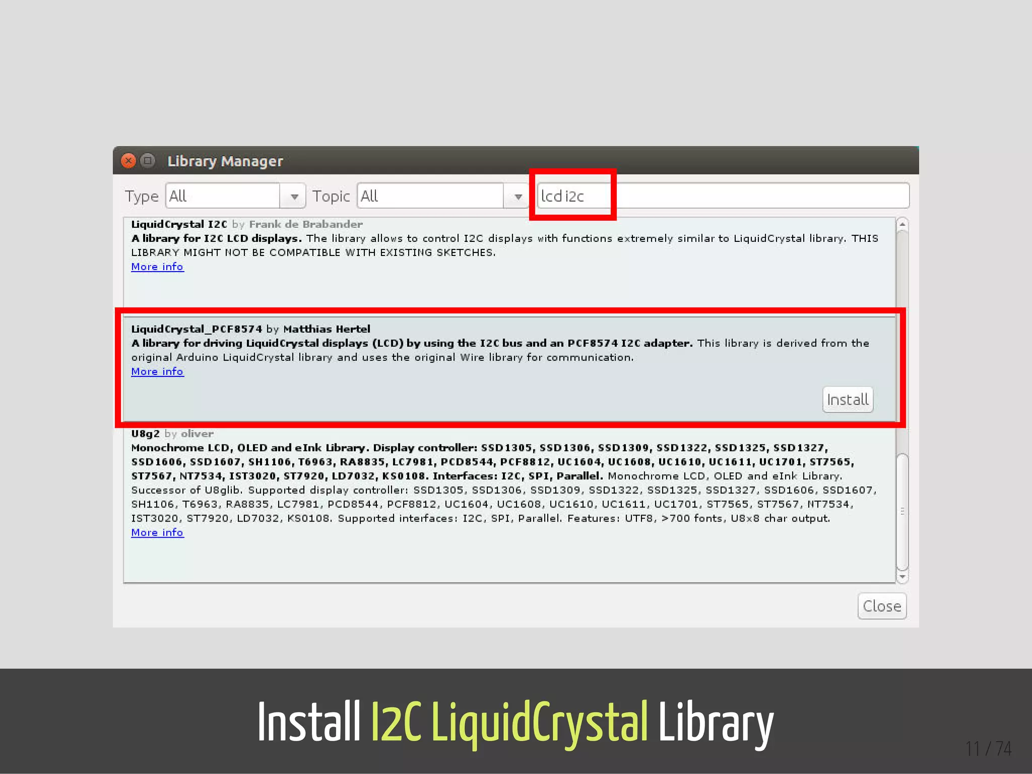
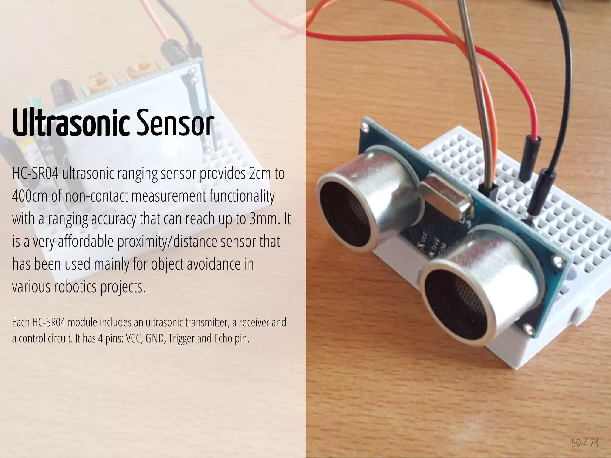
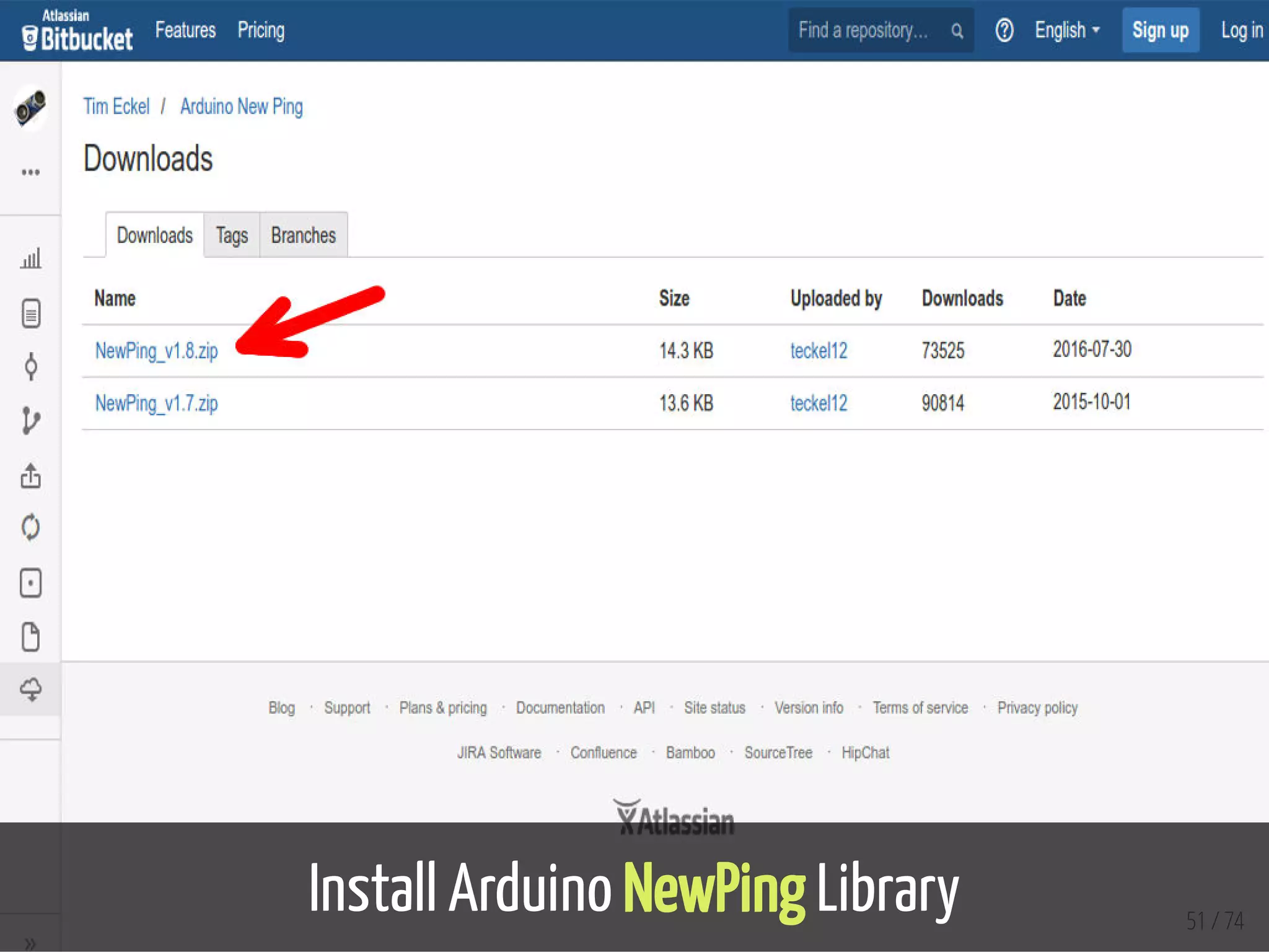
Download as PDF, PPTX

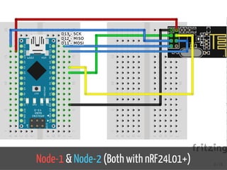
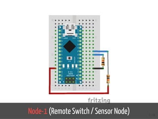

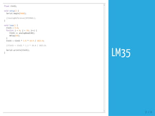
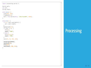
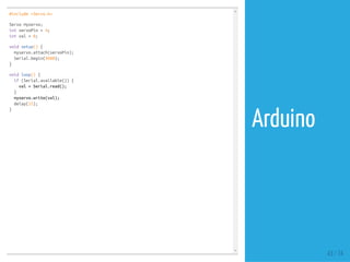
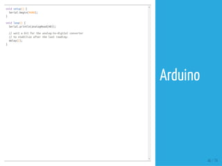
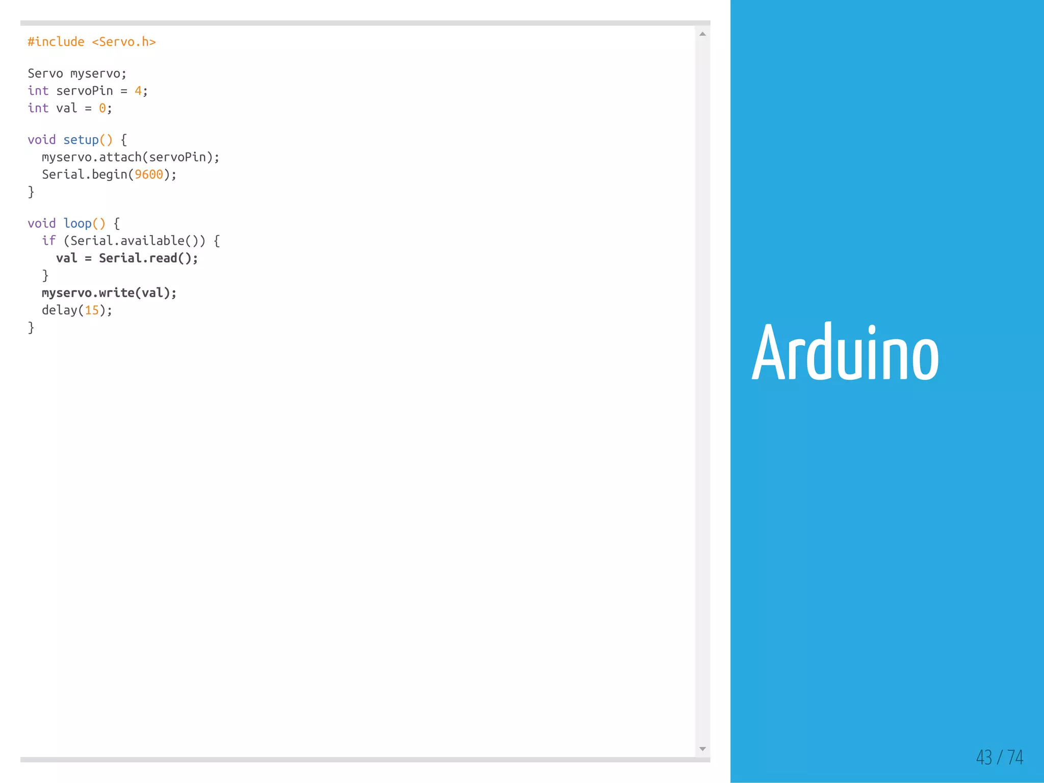
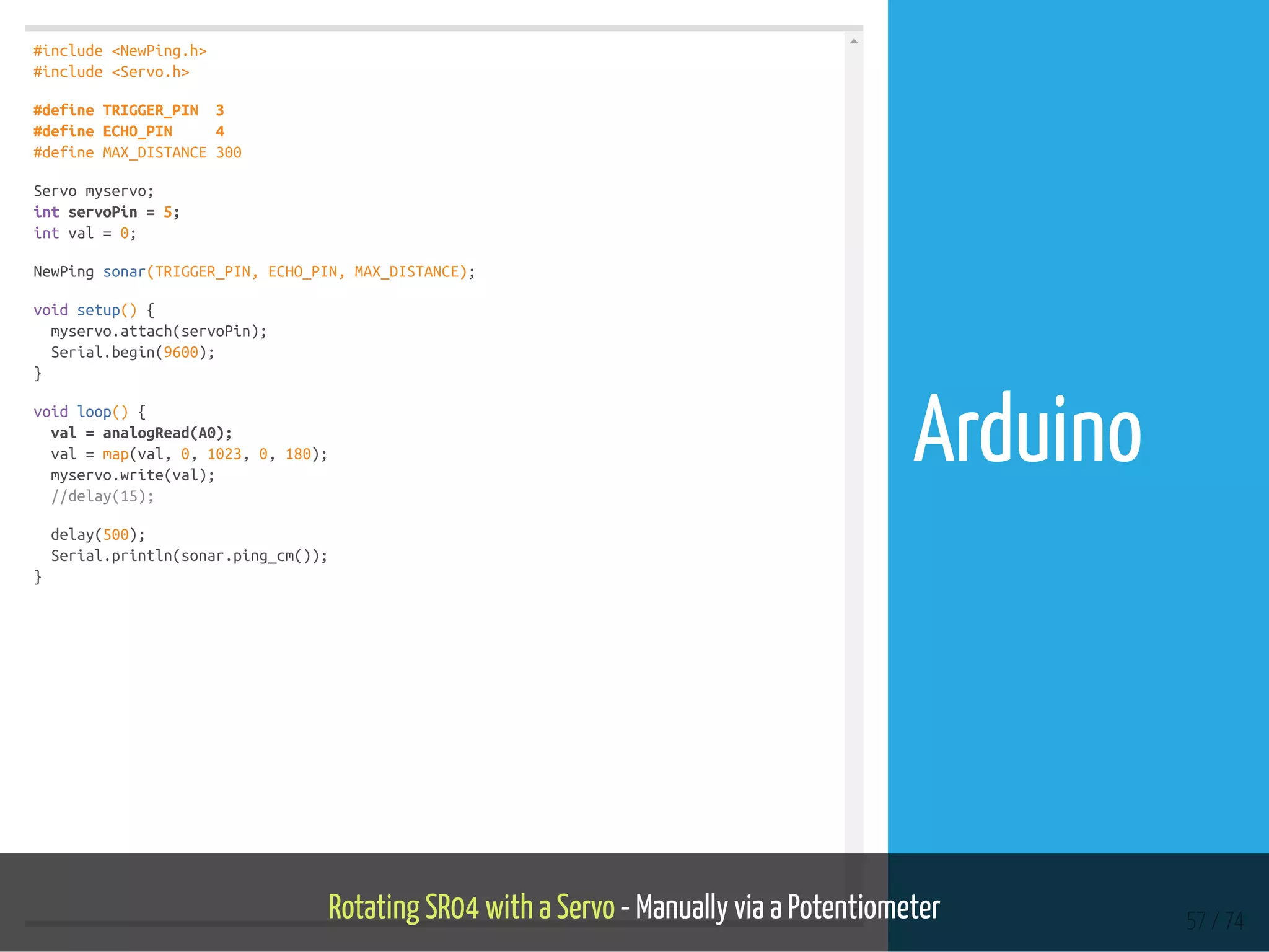
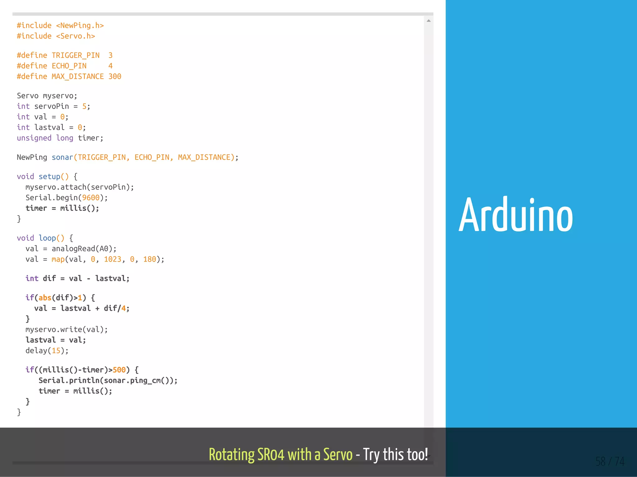
![#include <SPI.h>
#include "nRF24L01.h"
#include "RF24.h"
RF24 myRadio (7, 8);
const int SW1 = 5;
const int SW2 = 6;
byte addresses[][6] = {"1Node"};
int dataTransmitted;
int button1;
int button2;
void setup()
{
pinMode(SW1, INPUT);
pinMode(SW2, INPUT);
button1 = 0;
button2 = 1;
dataTransmitted = 10;
Serial.begin(115200);
delay(1000);
myRadio.begin();
myRadio.setRetries(0,15);
myRadio.setChannel(108);
myRadio.setPALevel(RF24_PA_MAX);
myRadio.openWritingPipe( addresses[0]);
delay(1000);
}
void loop()
{
int newButton = digitalRead(SW1);
if (newButton != button1) {
button1 = newButton;
if (button1 == HIGH){
dataTransmitted = 20;
} 12 / 74
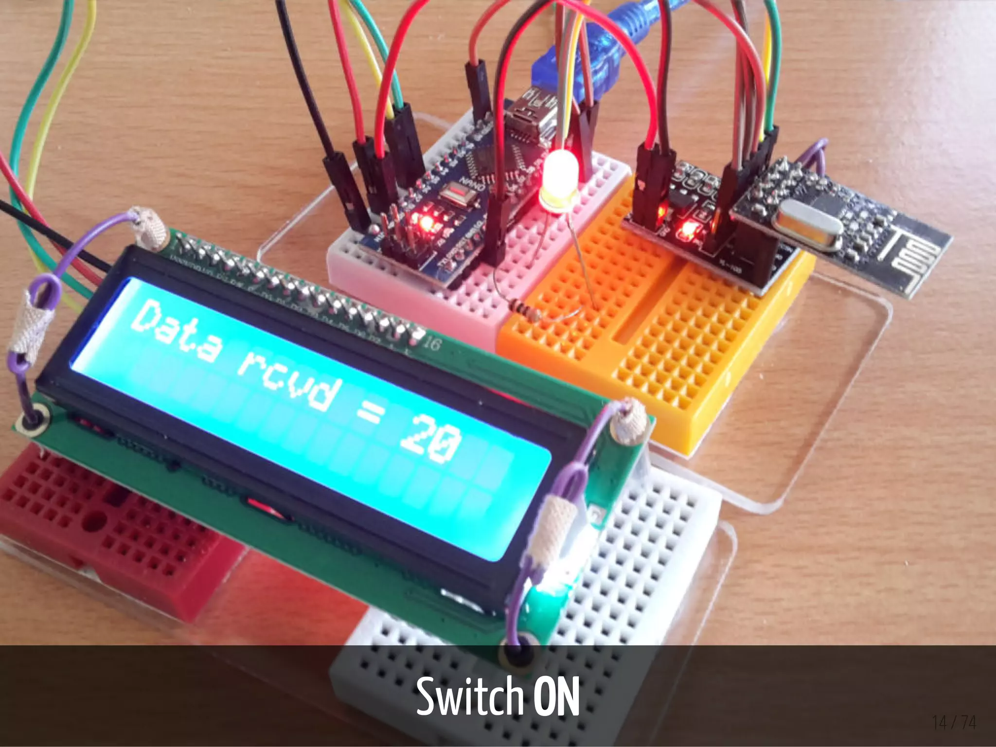
Node-1](https://image.slidesharecdn.com/ltka-sensorsandactuators-connectivityforlocalsensorsandactuators-eueungmulyana-170422084648/85/selected-input-output-sensors-and-actuators-12-320.jpg)
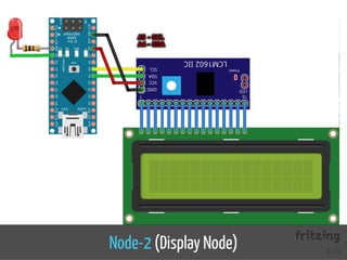
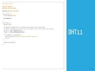
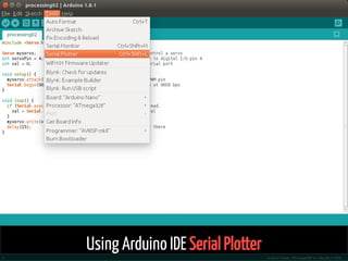
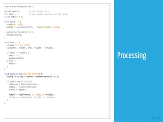
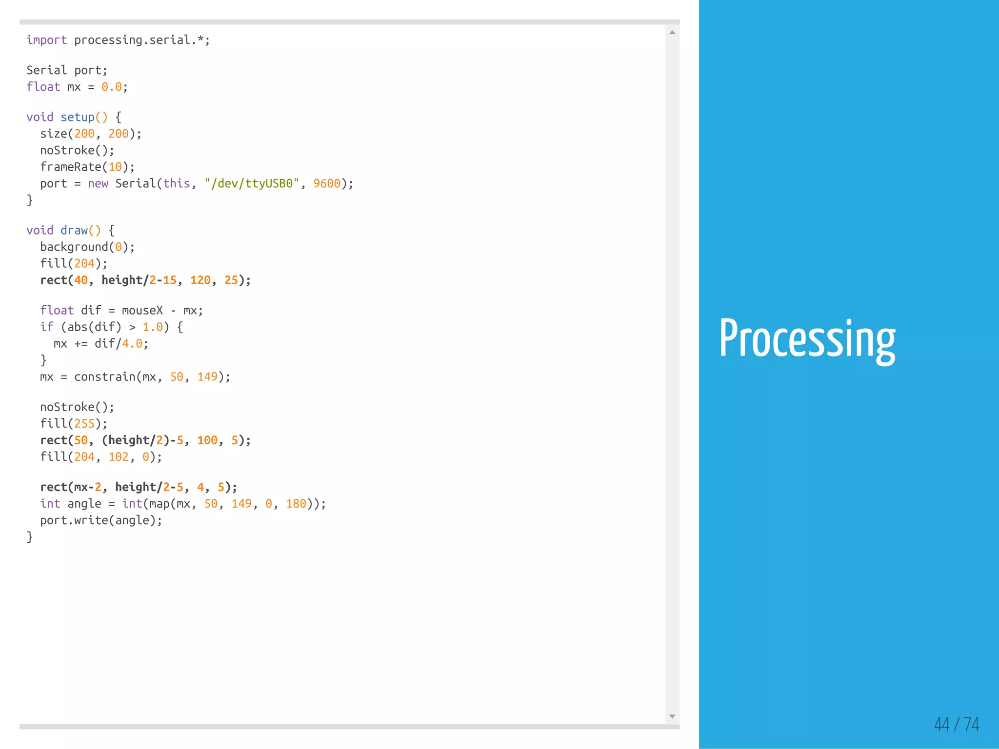
![#include <SPI.h>
#include "nRF24L01.h"
#include "RF24.h"
RF24 myRadio (7, 8);
byte addresses[][6] = {"1Node"};
int dataReceived;
const int LED = 2;
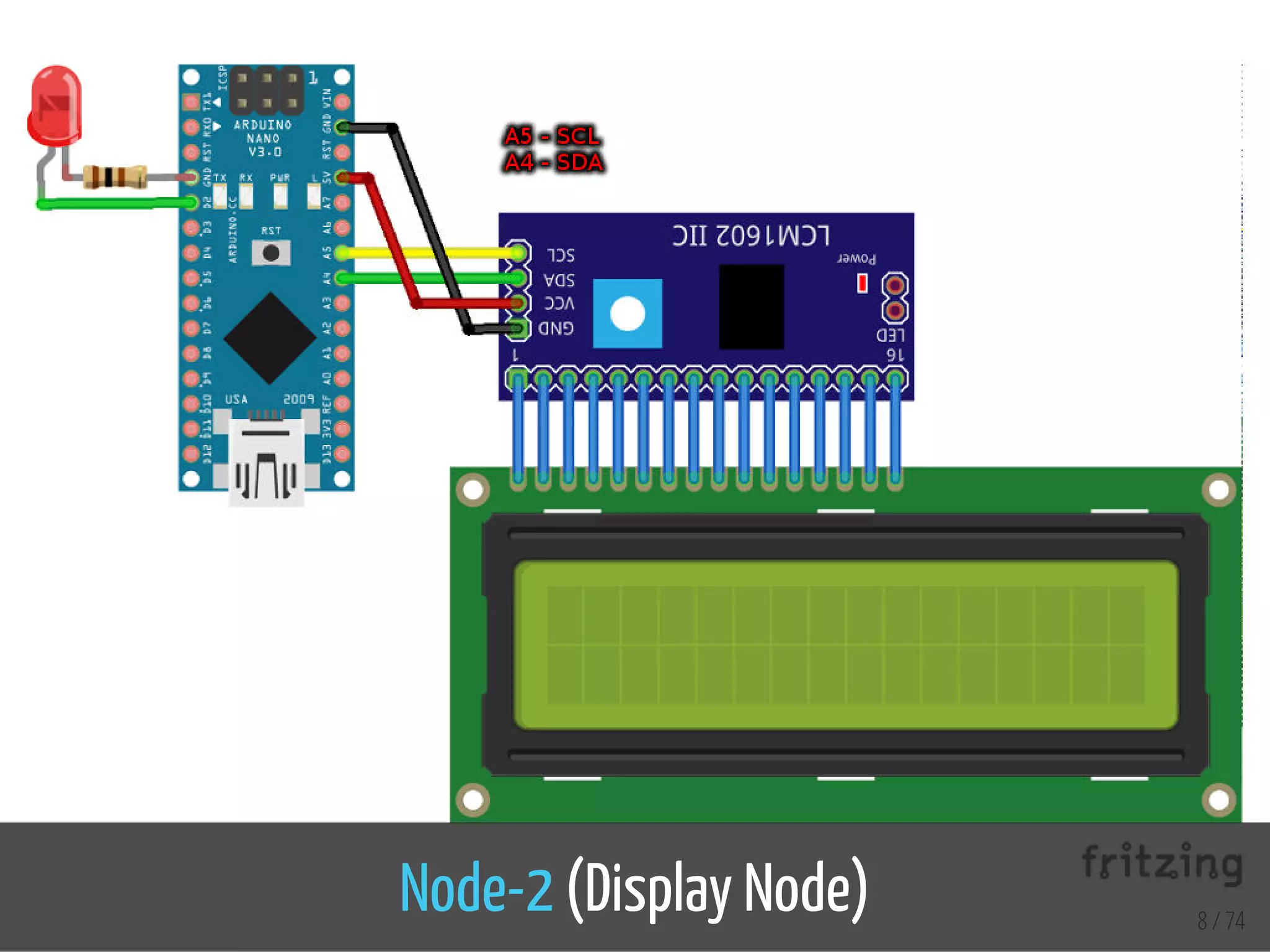
#include <Wire.h>
#include <LiquidCrystal_PCF8574.h>
LiquidCrystal_PCF8574 lcd(0x27);
int lcdexist;
unsigned long started_waiting_at = 0;
bool bklight = false;
void setup()
{
pinMode(LED, OUTPUT);
Serial.begin(115200);
delay(1000);
myRadio.begin();
myRadio.setAutoAck(1);
myRadio.setChannel(108);
myRadio.setPALevel(RF24_PA_MAX);
myRadio.openReadingPipe(1, addresses[0]);
myRadio.startListening();
Wire.begin();
Wire.beginTransmission(0x27);
lcdexist = Wire.endTransmission();
lcd.begin(16, 2);
}
void loop()
{
13 / 74
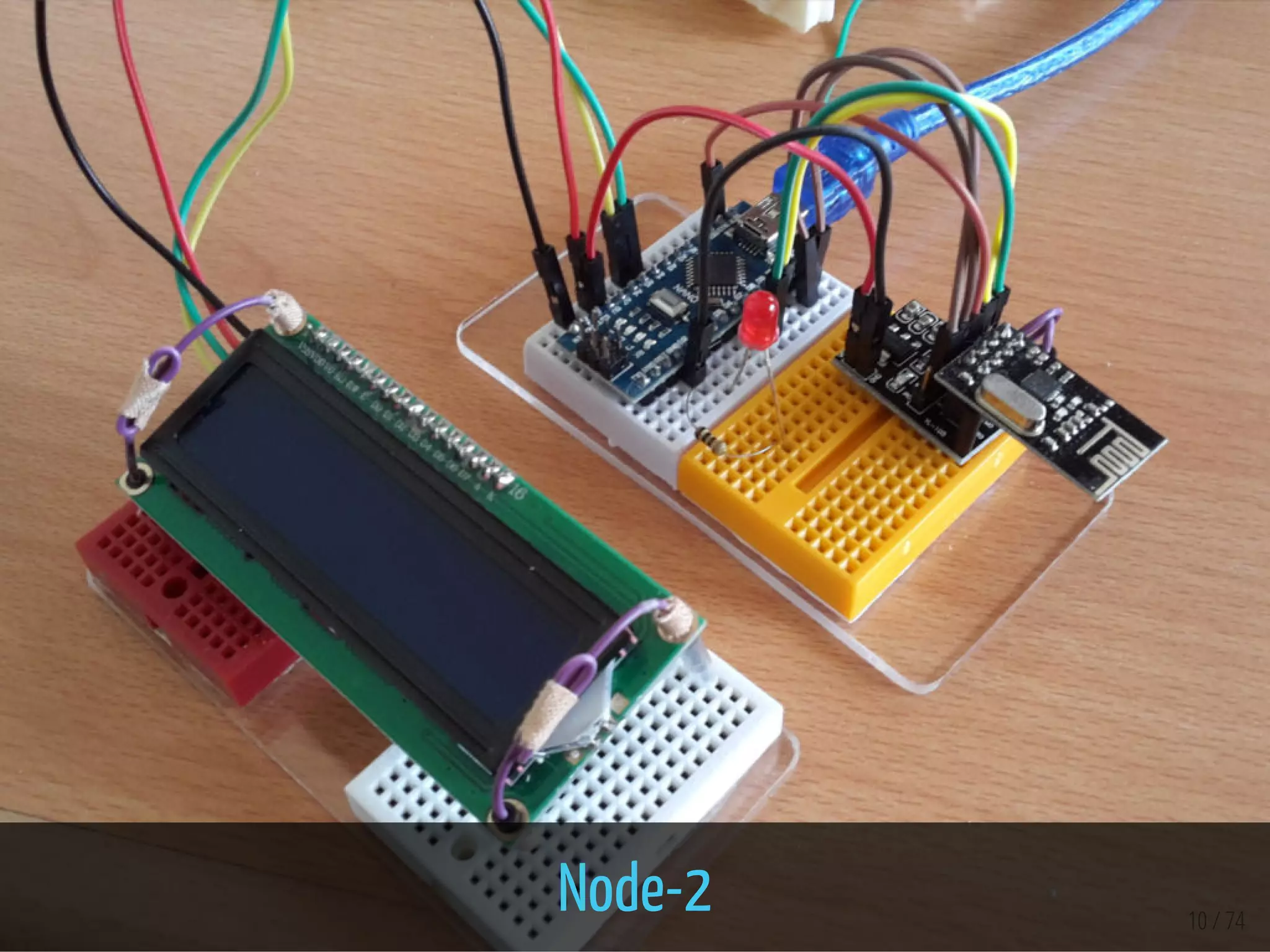
Node-2](https://image.slidesharecdn.com/ltka-sensorsandactuators-connectivityforlocalsensorsandactuators-eueungmulyana-170422084648/85/selected-input-output-sensors-and-actuators-13-320.jpg)


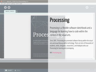


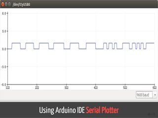
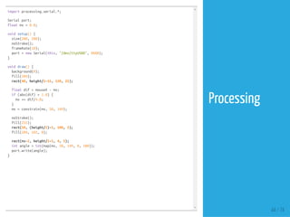
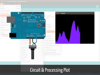

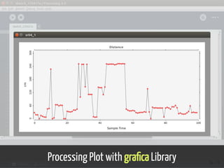
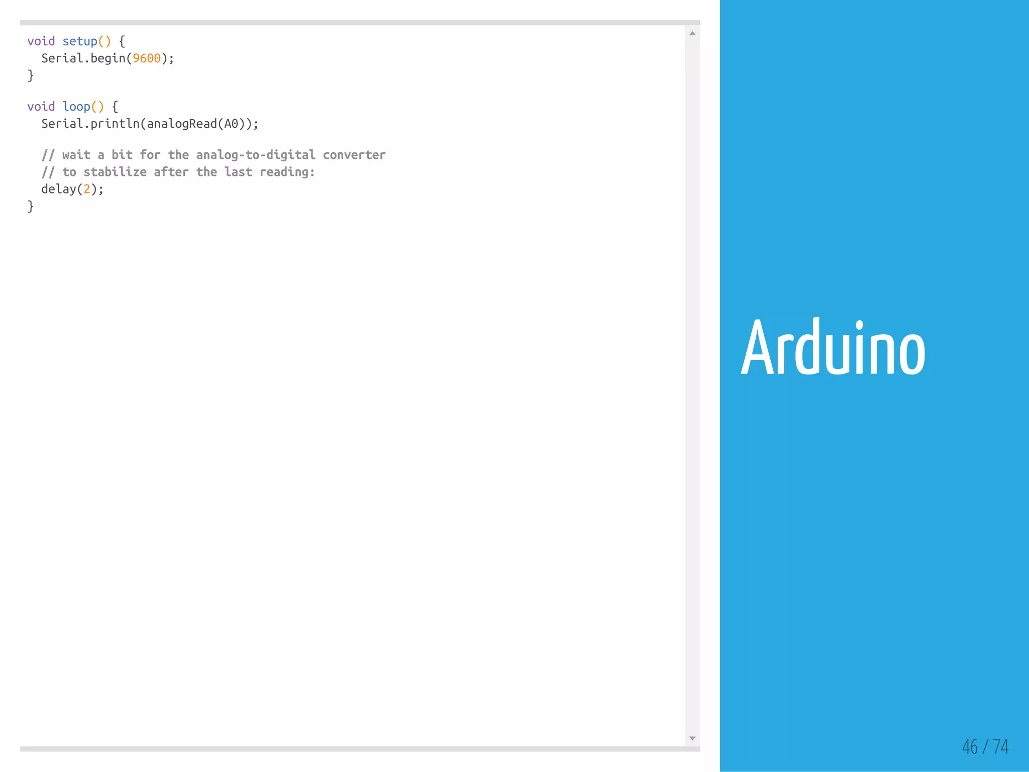
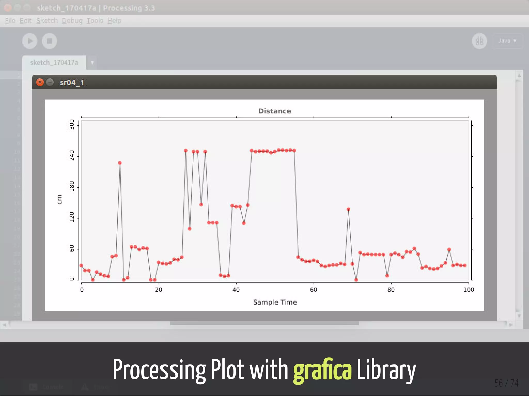
![import grafica.*;
import processing.serial.*;
GPlot plot;
int i = 0;
int points = 100;
public float[] values;
Serial myPort;
float inByte = 0;
void setup(){
size (900,450);
myPort = new Serial(this, "/dev/ttyUSB0", 9600);
GPointsArray points1 = new GPointsArray(points);
values = new float[points];
for (i = 0; i < points; i++) {
points1.add(i,0);
values[i]=0;
}
plot = new GPlot(this);
plot.setPos(25, 20);
plot.setDim(750, 310);
plot.setXLim(0, points);
plot.setYLim(0, 310);
plot.setTitleText("Distance");
plot.getXAxis().setAxisLabelText("Sample Time");
plot.getYAxis().setAxisLabelText("cm");
plot.setPoints(points1);
}
void draw() {
background(150);
GPointsArray points1 = new GPointsArray(points);
for (i = 0; i < values.length; i++) { 55 / 74
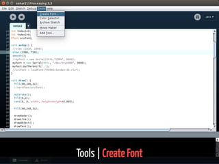
Processing](https://image.slidesharecdn.com/ltka-sensorsandactuators-connectivityforlocalsensorsandactuators-eueungmulyana-170422084648/85/selected-input-output-sensors-and-actuators-55-320.jpg)


![#include <SPI.h>
#include "nRF24L01.h"
#include "RF24.h"
RF24 myRadio (7, 8);
const int SW1 = 5;
const int SW2 = 6;
byte addresses[][6] = {"1Node"};
int dataTransmitted;
int button1;
int button2;
void setup()
{
pinMode(SW1, INPUT);
pinMode(SW2, INPUT);
button1 = 0;
button2 = 1;
dataTransmitted = 10;
Serial.begin(115200);
delay(1000);
myRadio.begin();
myRadio.setRetries(0,15);
myRadio.setChannel(108);
myRadio.setPALevel(RF24_PA_MAX);
myRadio.openWritingPipe( addresses[0]);
delay(1000);
}
void loop()
{
int newButton = digitalRead(SW1);
if (newButton != button1) {
button1 = newButton;
if (button1 == HIGH){
dataTransmitted = 20;
} 12 / 74
Node-1](https://image.slidesharecdn.com/ltka-sensorsandactuators-connectivityforlocalsensorsandactuators-eueungmulyana-170422084648/75/selected-input-output-sensors-and-actuators-12-2048.jpg)
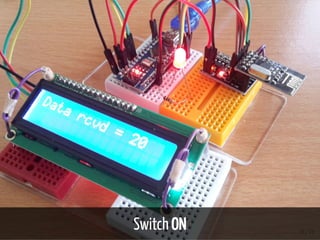
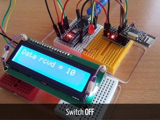
![#include <SPI.h>
#include "nRF24L01.h"
#include "RF24.h"
RF24 myRadio (7, 8);
byte addresses[][6] = {"1Node"};
int dataReceived;
const int LED = 2;
#include <Wire.h>
#include <LiquidCrystal_PCF8574.h>
LiquidCrystal_PCF8574 lcd(0x27);
int lcdexist;
unsigned long started_waiting_at = 0;
bool bklight = false;
void setup()
{
pinMode(LED, OUTPUT);
Serial.begin(115200);
delay(1000);
myRadio.begin();
myRadio.setAutoAck(1);
myRadio.setChannel(108);
myRadio.setPALevel(RF24_PA_MAX);
myRadio.openReadingPipe(1, addresses[0]);
myRadio.startListening();
Wire.begin();
Wire.beginTransmission(0x27);
lcdexist = Wire.endTransmission();
lcd.begin(16, 2);
}
void loop()
{
13 / 74
Node-2](https://image.slidesharecdn.com/ltka-sensorsandactuators-connectivityforlocalsensorsandactuators-eueungmulyana-170422084648/75/selected-input-output-sensors-and-actuators-13-2048.jpg)


![import grafica.*;
import processing.serial.*;
GPlot plot;
int i = 0;
int points = 100;
public float[] values;
Serial myPort;
float inByte = 0;
void setup(){
size (900,450);
myPort = new Serial(this, "/dev/ttyUSB0", 9600);
GPointsArray points1 = new GPointsArray(points);
values = new float[points];
for (i = 0; i < points; i++) {
points1.add(i,0);
values[i]=0;
}
plot = new GPlot(this);
plot.setPos(25, 20);
plot.setDim(750, 310);
plot.setXLim(0, points);
plot.setYLim(0, 310);
plot.setTitleText("Distance");
plot.getXAxis().setAxisLabelText("Sample Time");
plot.getYAxis().setAxisLabelText("cm");
plot.setPoints(points1);
}
void draw() {
background(150);
GPointsArray points1 = new GPointsArray(points);
for (i = 0; i < values.length; i++) { 55 / 74
Processing](https://image.slidesharecdn.com/ltka-sensorsandactuators-connectivityforlocalsensorsandactuators-eueungmulyana-170422084648/75/selected-input-output-sensors-and-actuators-55-2048.jpg)


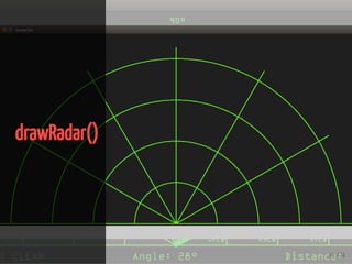
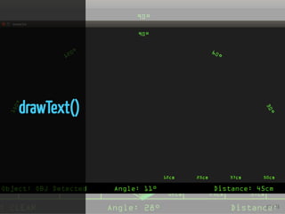
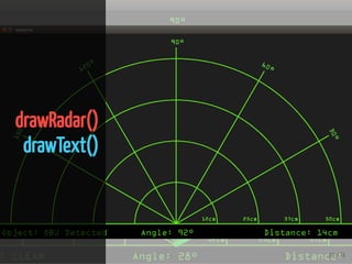
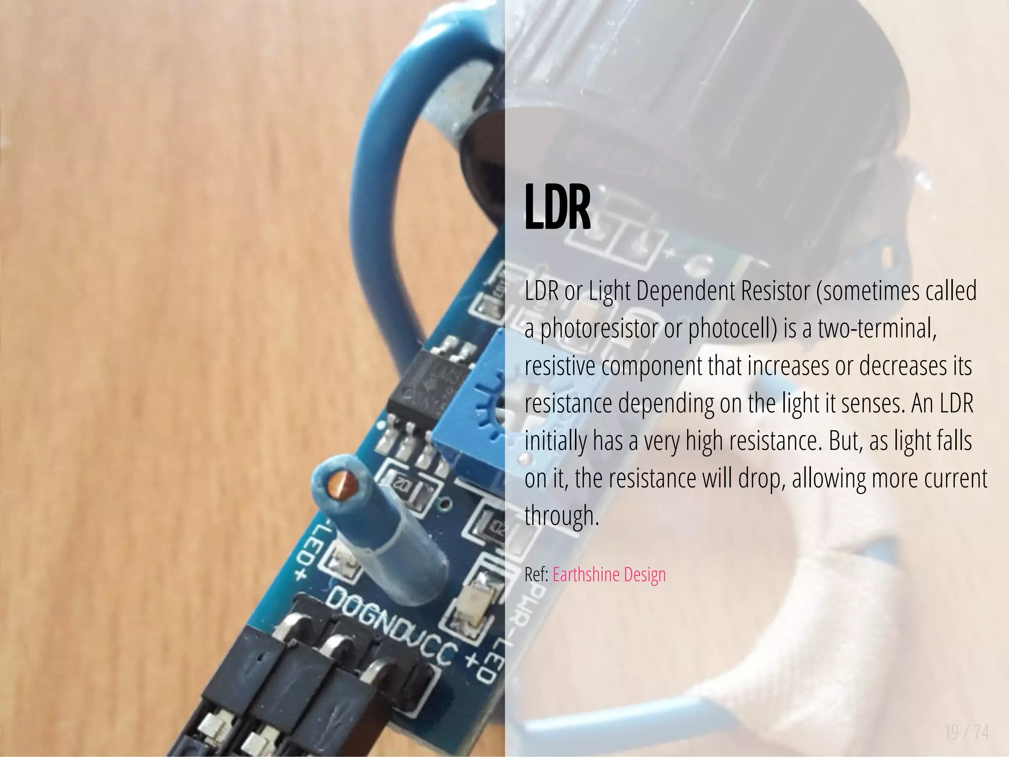
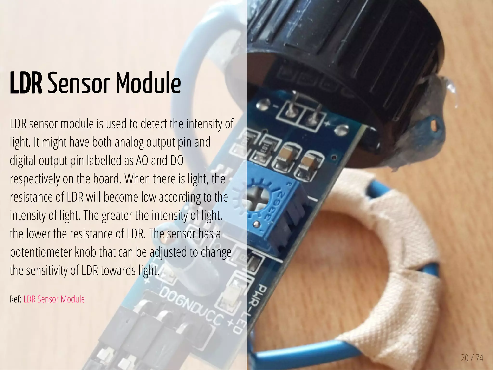
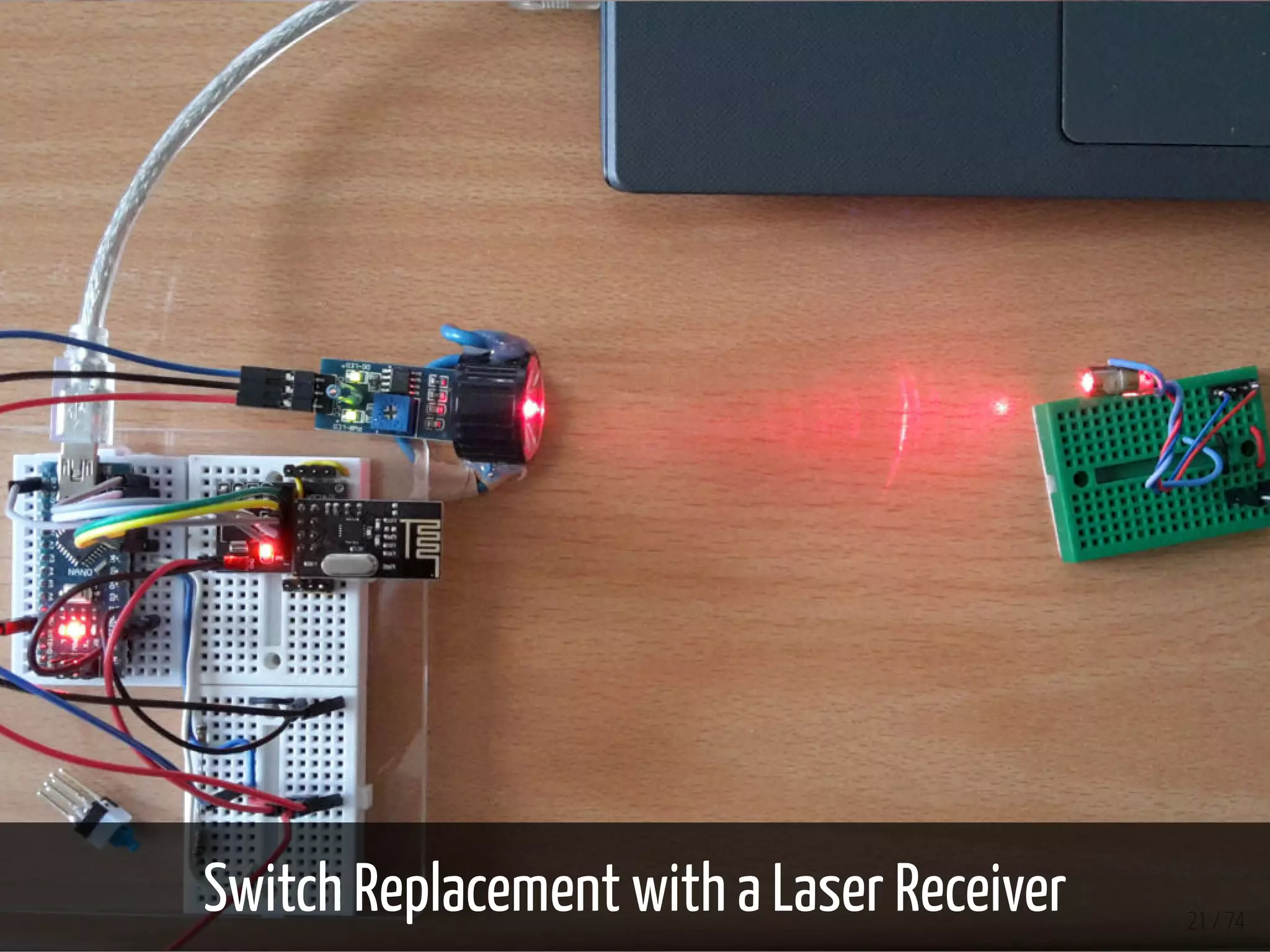
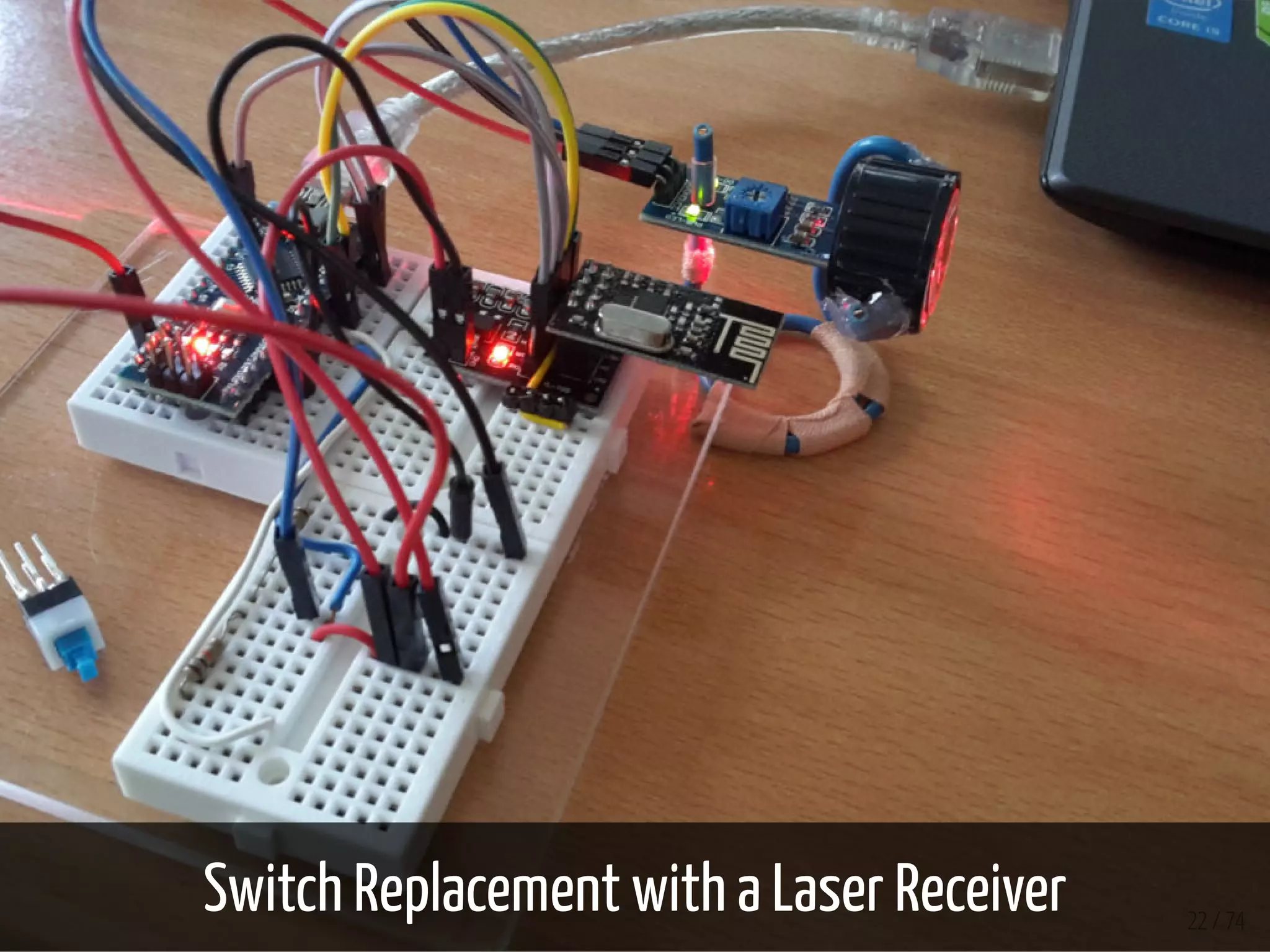
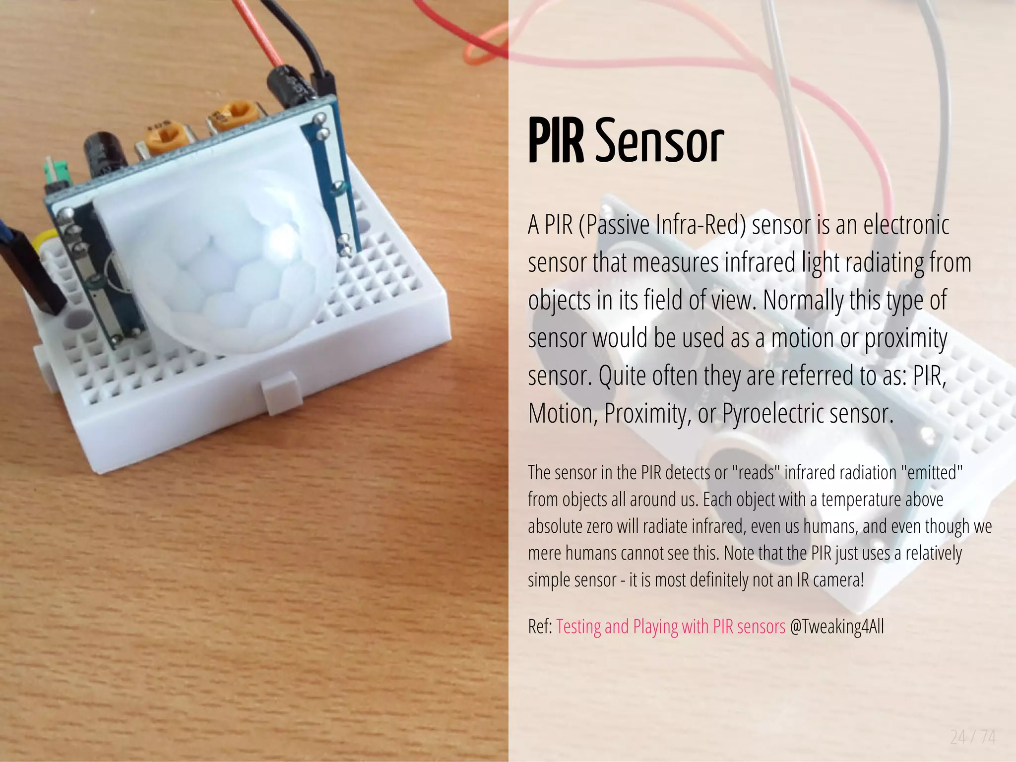
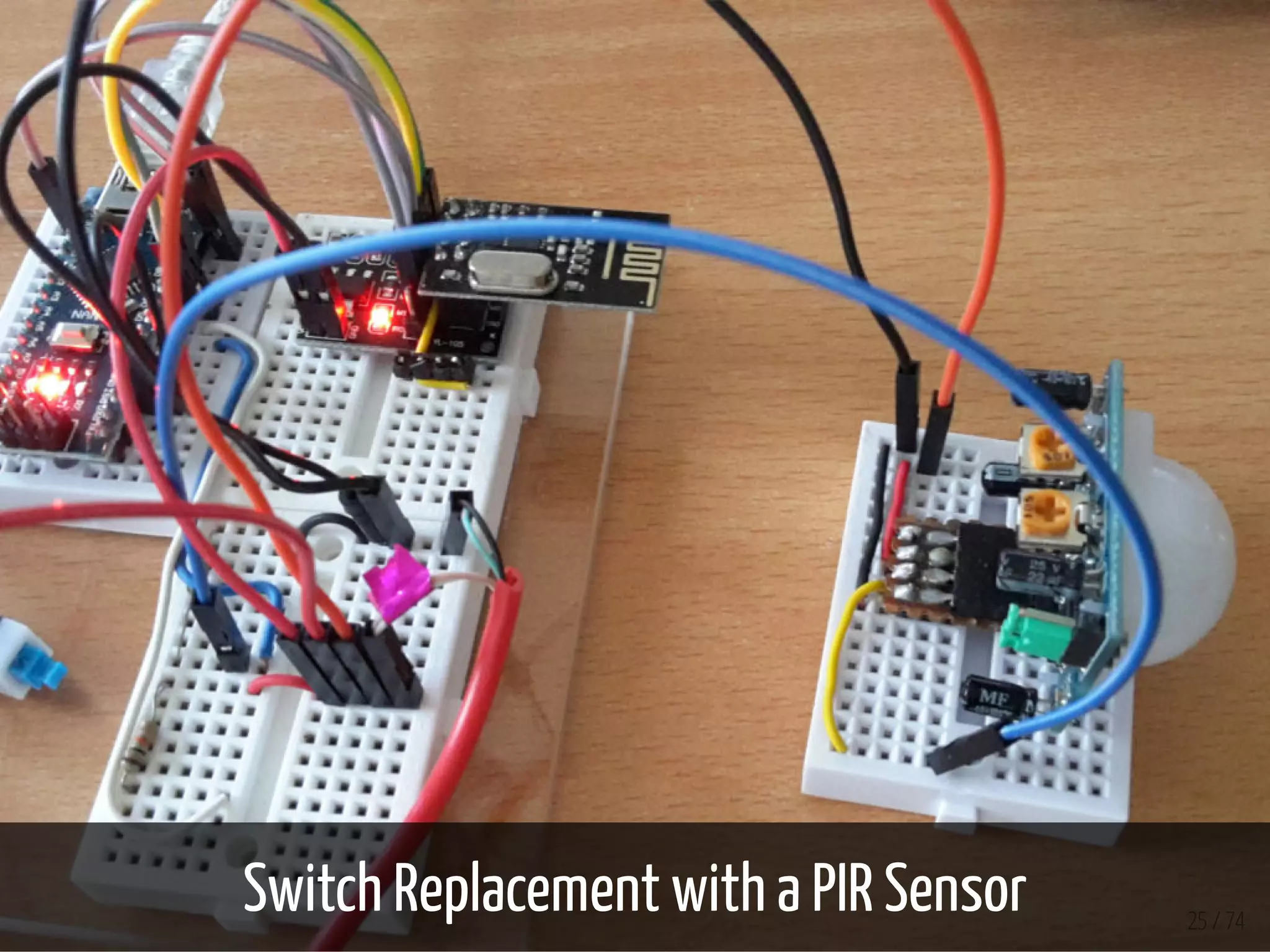
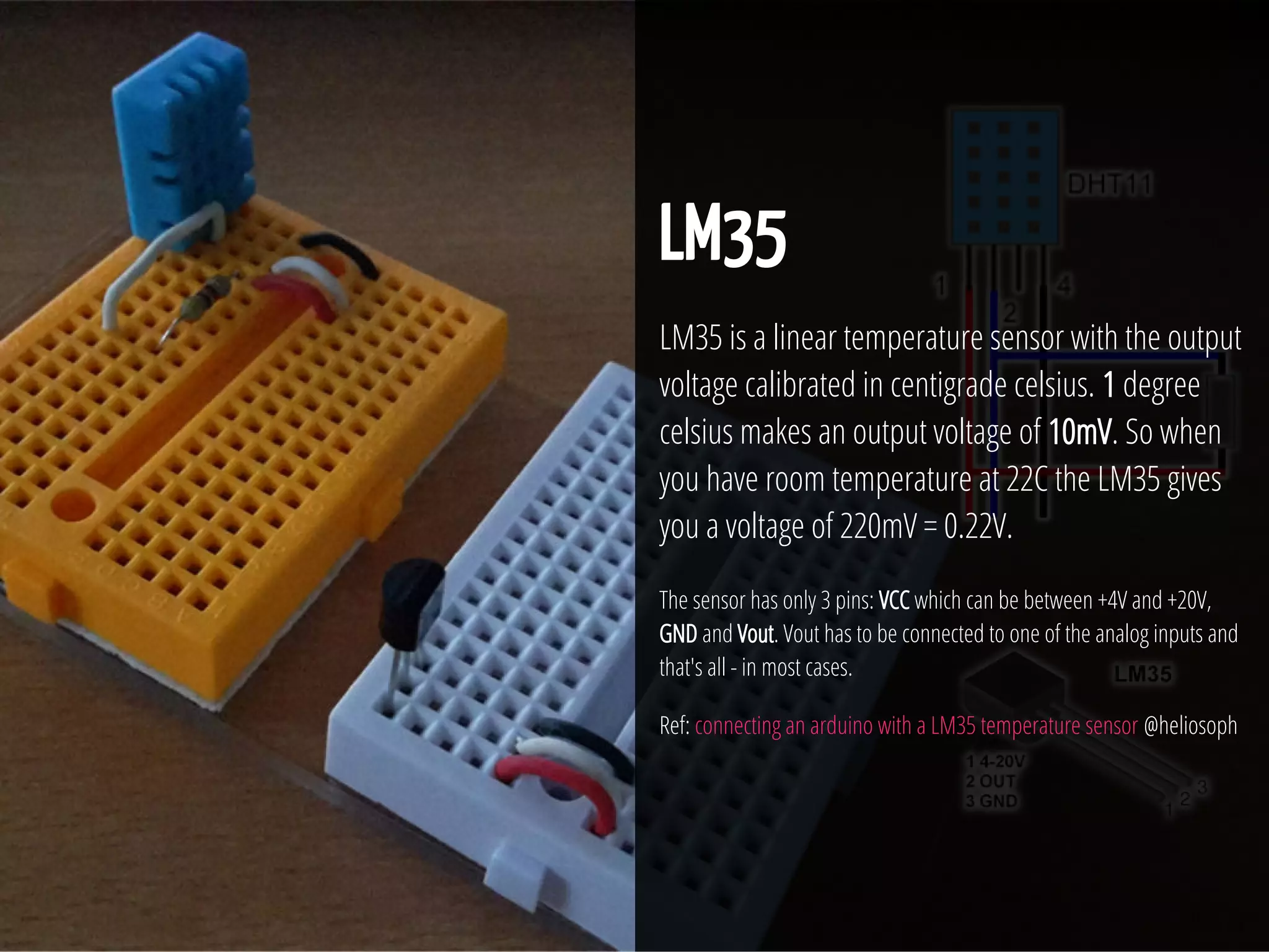
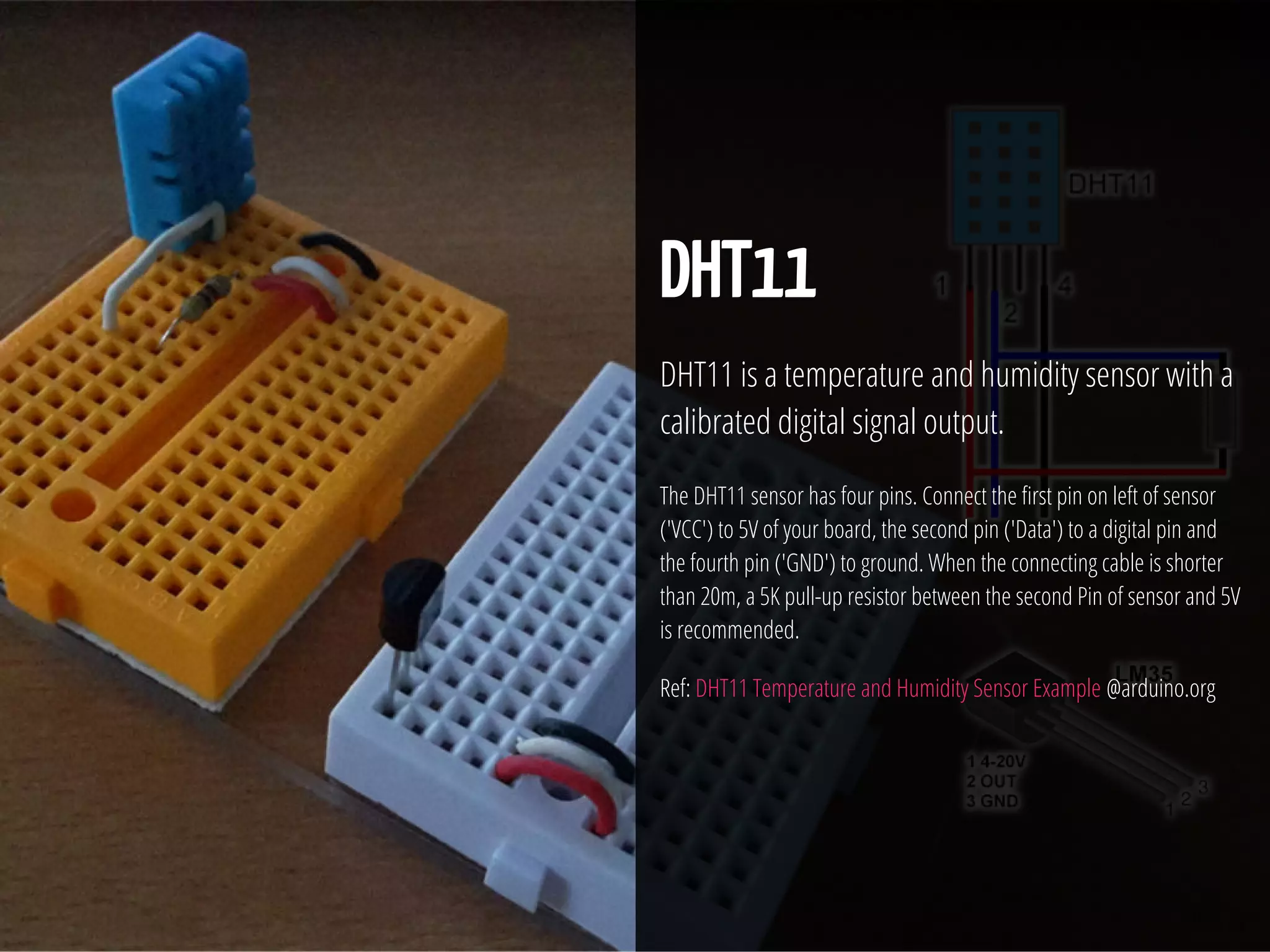
The document outlines a series of projects involving sensors and actuators, focusing on integrating various sensing technologies such as light/laser sensors, PIR sensors, and temperature sensors with Arduino hardware. It includes detailed setups, code snippets, and visualizations using Processing to display sensor data. The content serves as a guide for users to understand and implement sensor-based projects with Arduino and Processing for data visualization and interaction.


