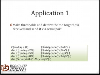
Downloaded 106 times

![Temperature sensors
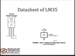
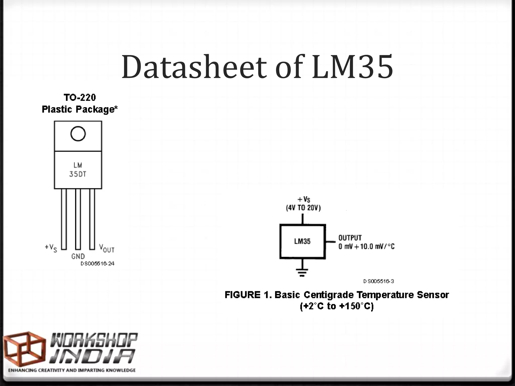
0 Gives a Vout propotional to ambient room
temperature.
0 Concept : as temperature increases, voltage
across a p-n junction increases at a known
rate. (in this case Vbe)
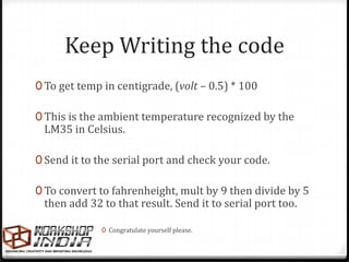
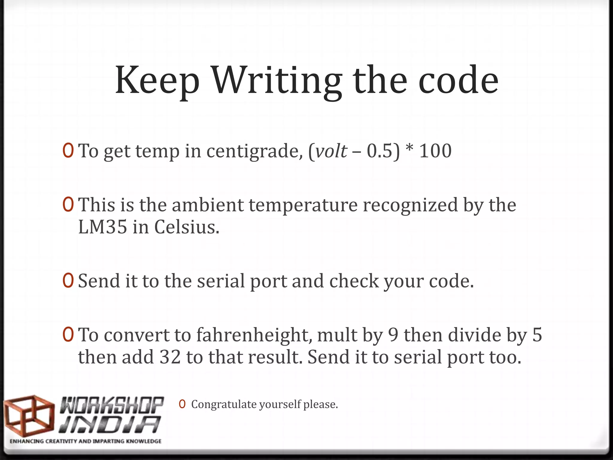
0 Voltage at Anlg.Pin in Volts = (reading
from ADC) * (5/1024) V
0 Centigrade temperature = [(analog voltage
in V) – 0.5] * 100](https://image.slidesharecdn.com/04-peripherals-120720014450-phpapp01/85/04-Arduino-Peripheral-Interfacing-2-320.jpg)


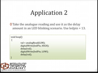


![Temperature sensors
0 Gives a Vout propotional to ambient room
temperature.
0 Concept : as temperature increases, voltage
across a p-n junction increases at a known
rate. (in this case Vbe)
0 Voltage at Anlg.Pin in Volts = (reading
from ADC) * (5/1024) V
0 Centigrade temperature = [(analog voltage
in V) – 0.5] * 100](https://image.slidesharecdn.com/04-peripherals-120720014450-phpapp01/75/04-Arduino-Peripheral-Interfacing-2-2048.jpg)


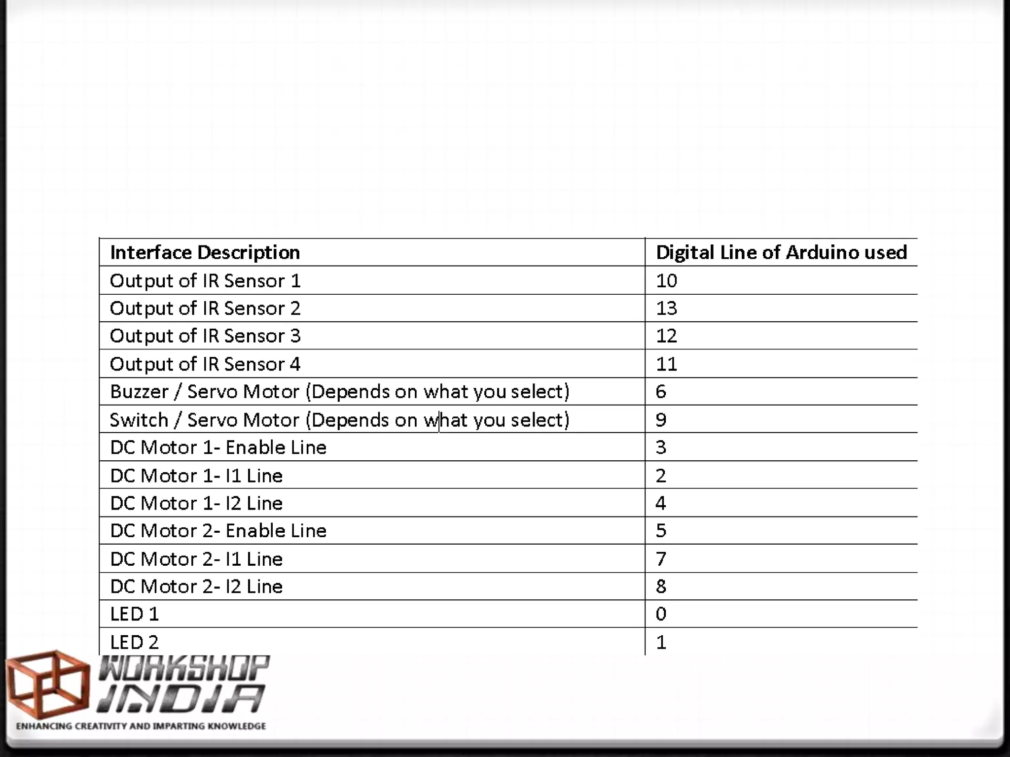
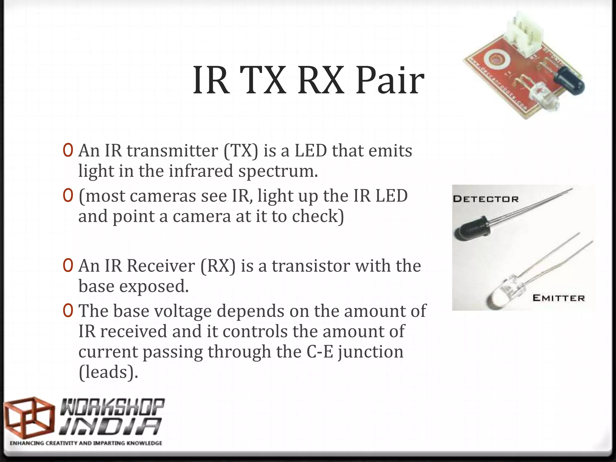
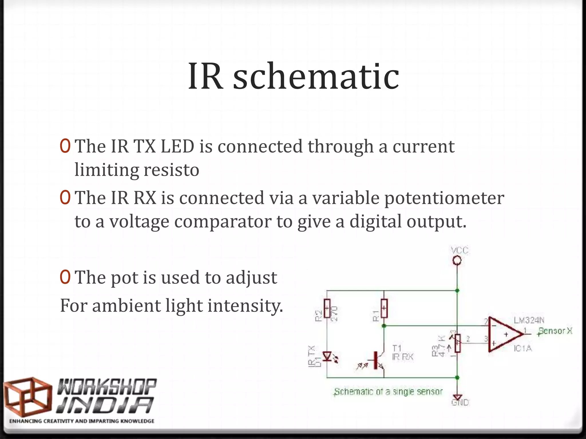
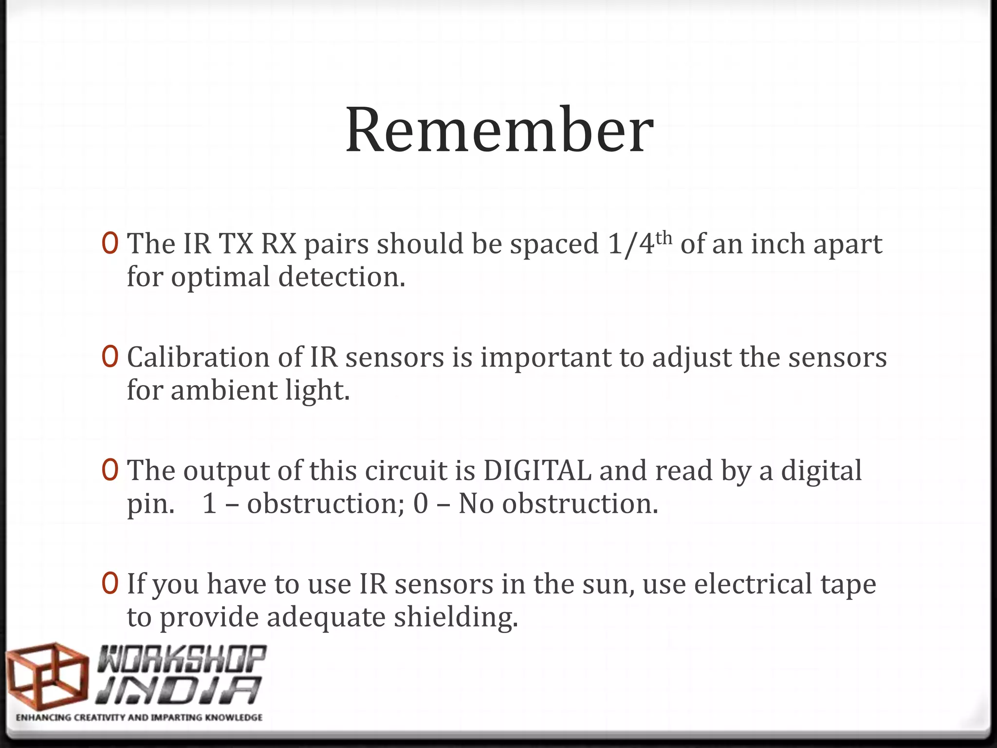
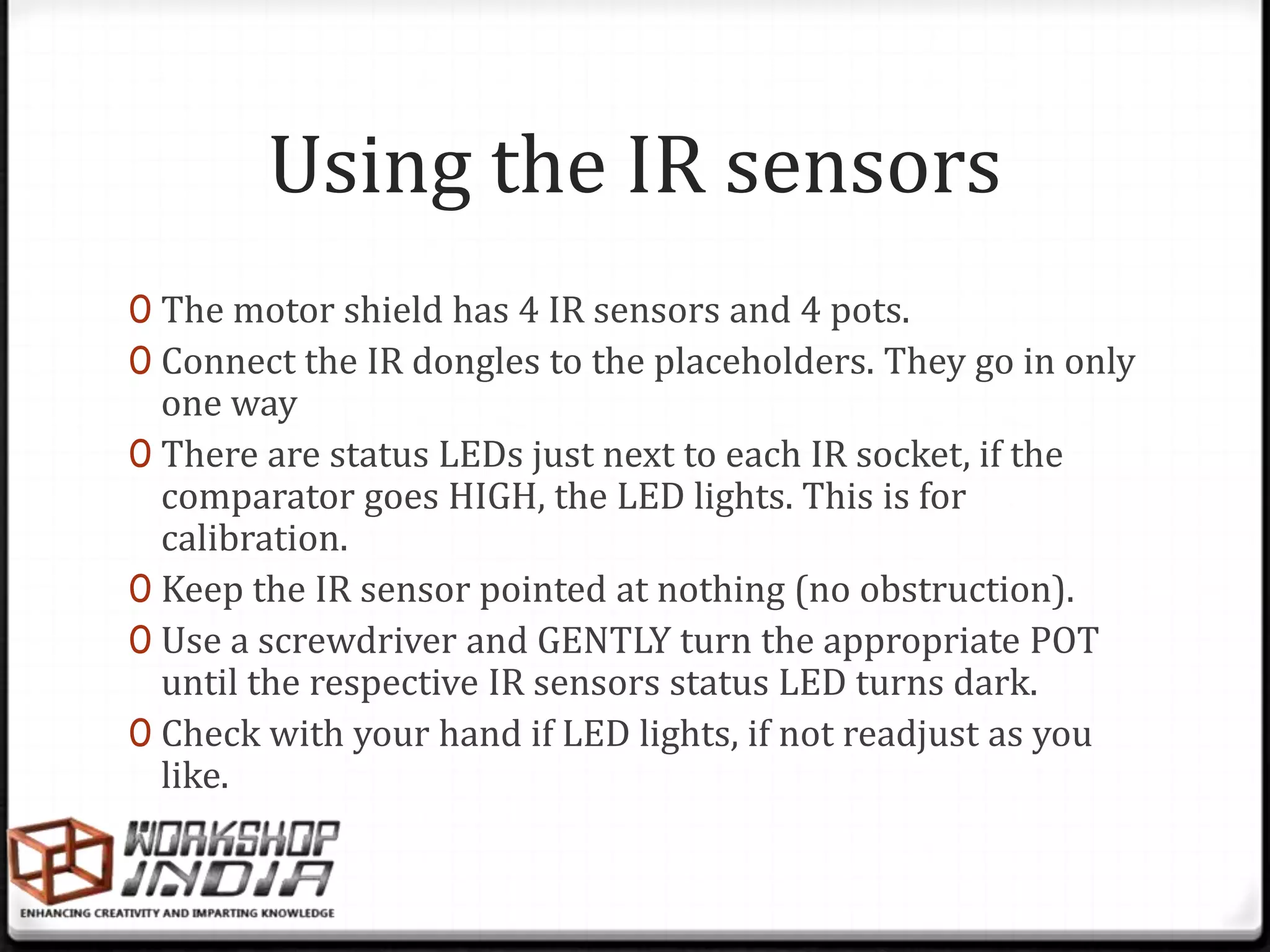
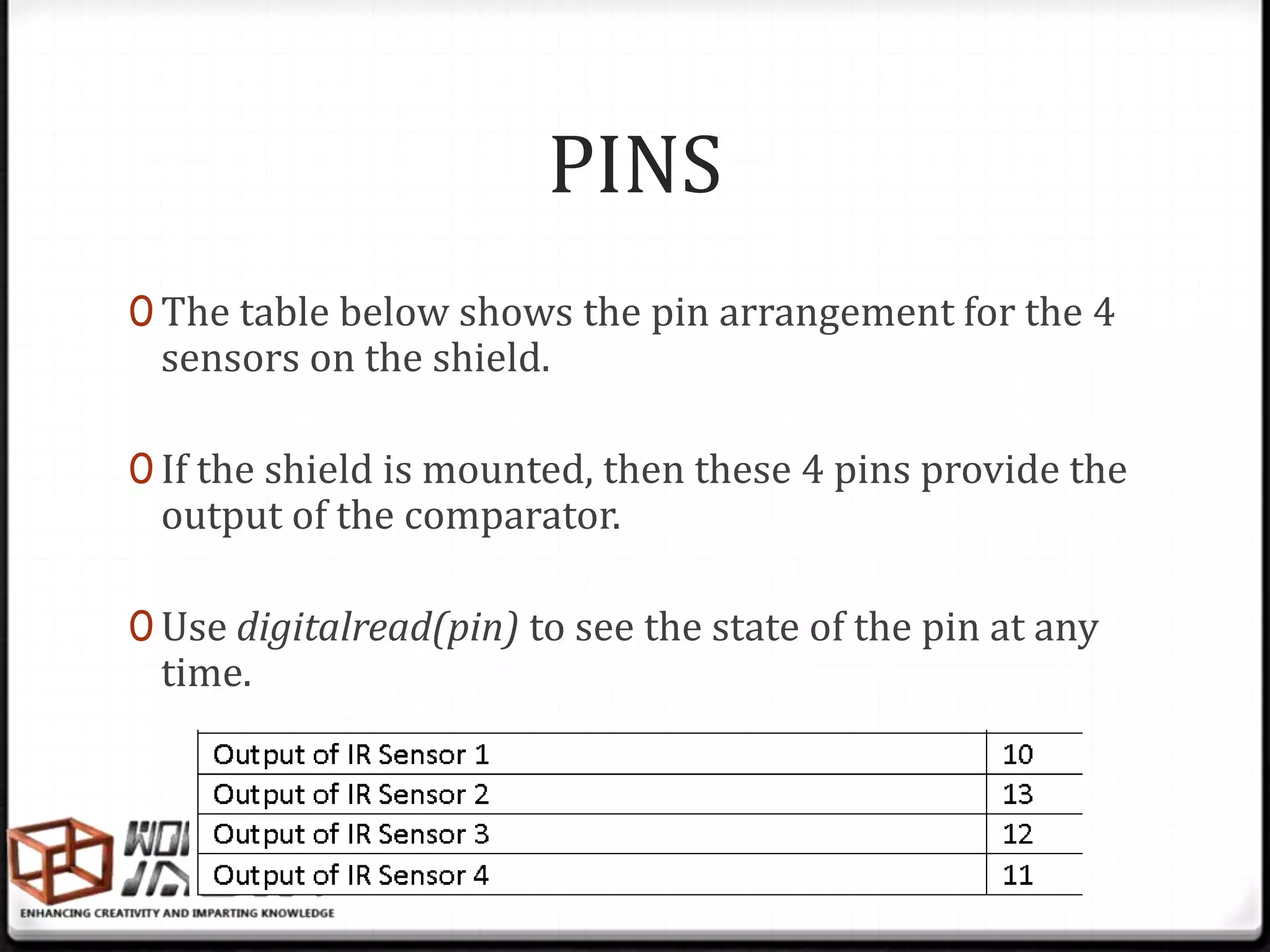


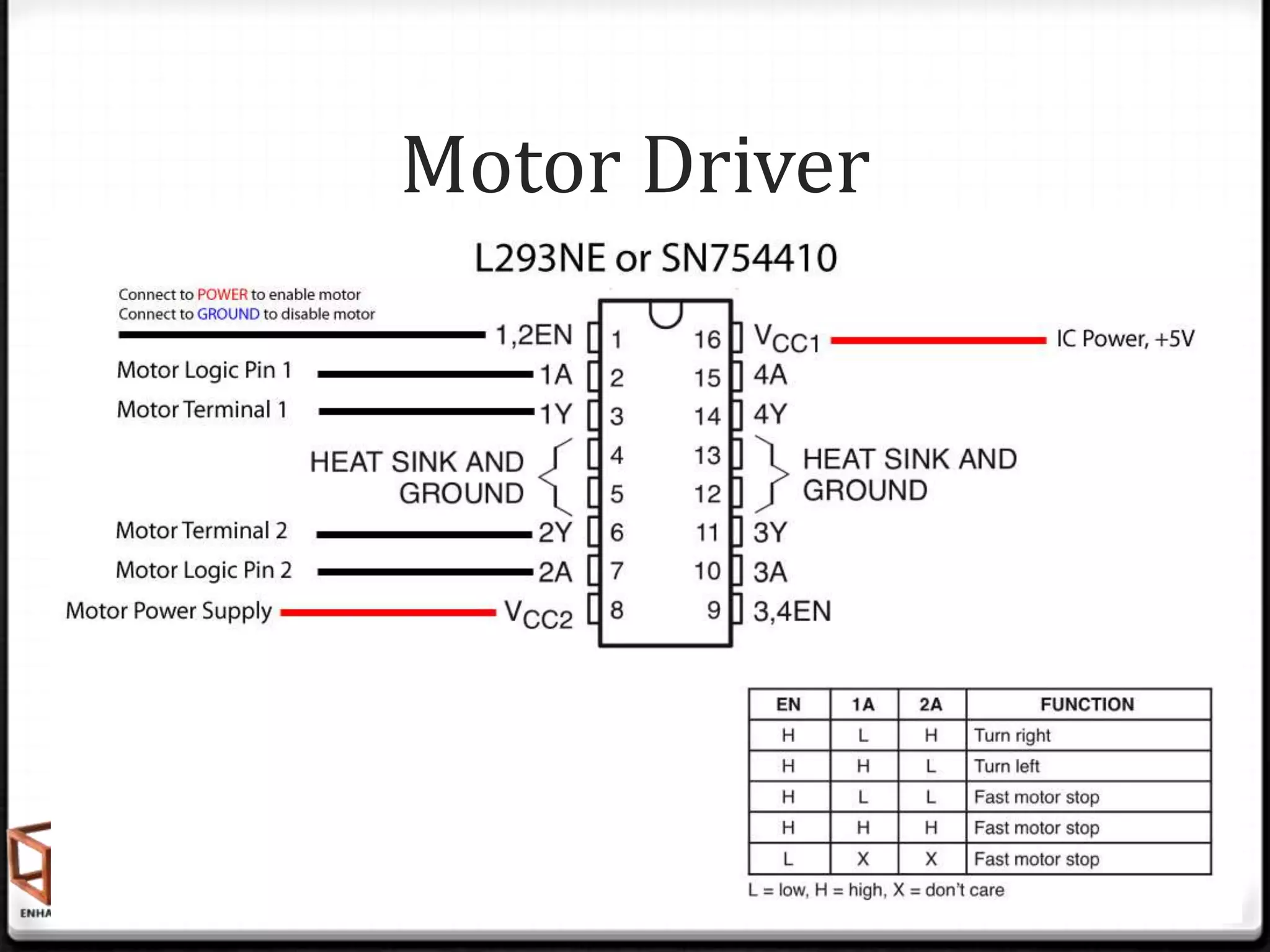


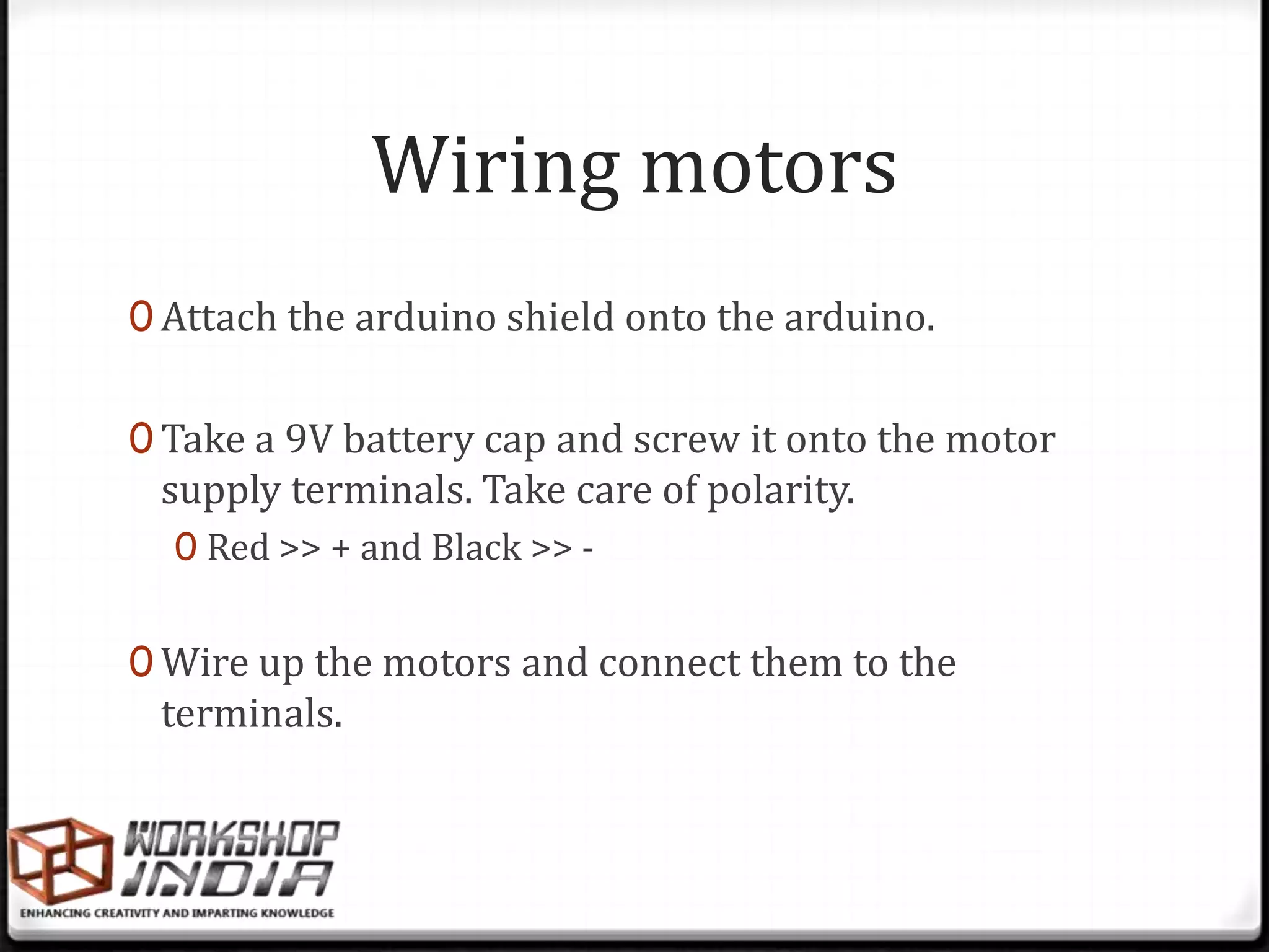


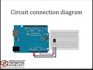
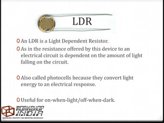
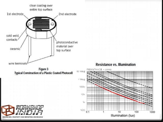
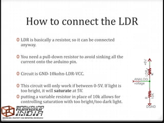
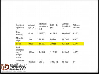
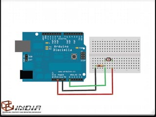
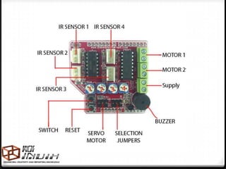
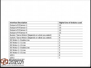
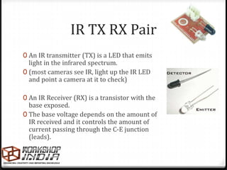
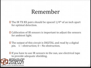
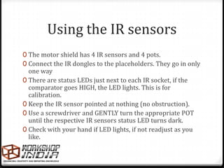
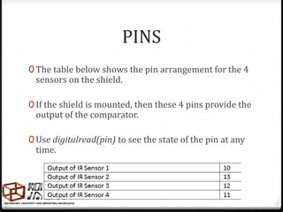
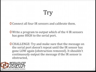
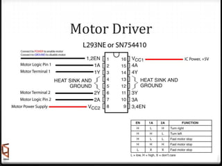
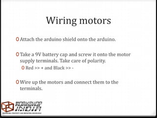
The document provides information about temperature sensors, light dependent resistors (LDRs), infrared (IR) sensor pairs, DC motors, and motor drivers/shields. It discusses how these components work, how to connect them to an Arduino, and examples of coding to read sensor values and control motors. Code snippets are provided for reading a temperature sensor, LDR, and IR sensors and controlling motors with a motor driver shield.


