Download to read offline

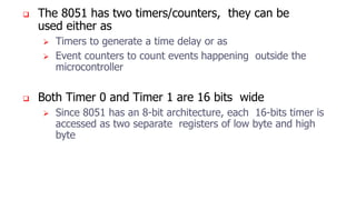
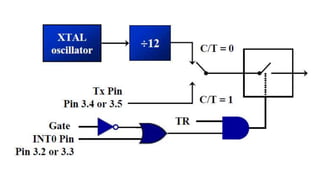
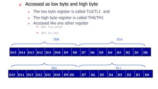
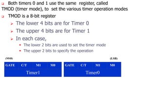
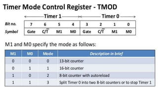
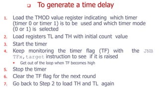
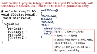
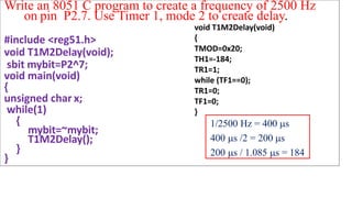
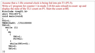


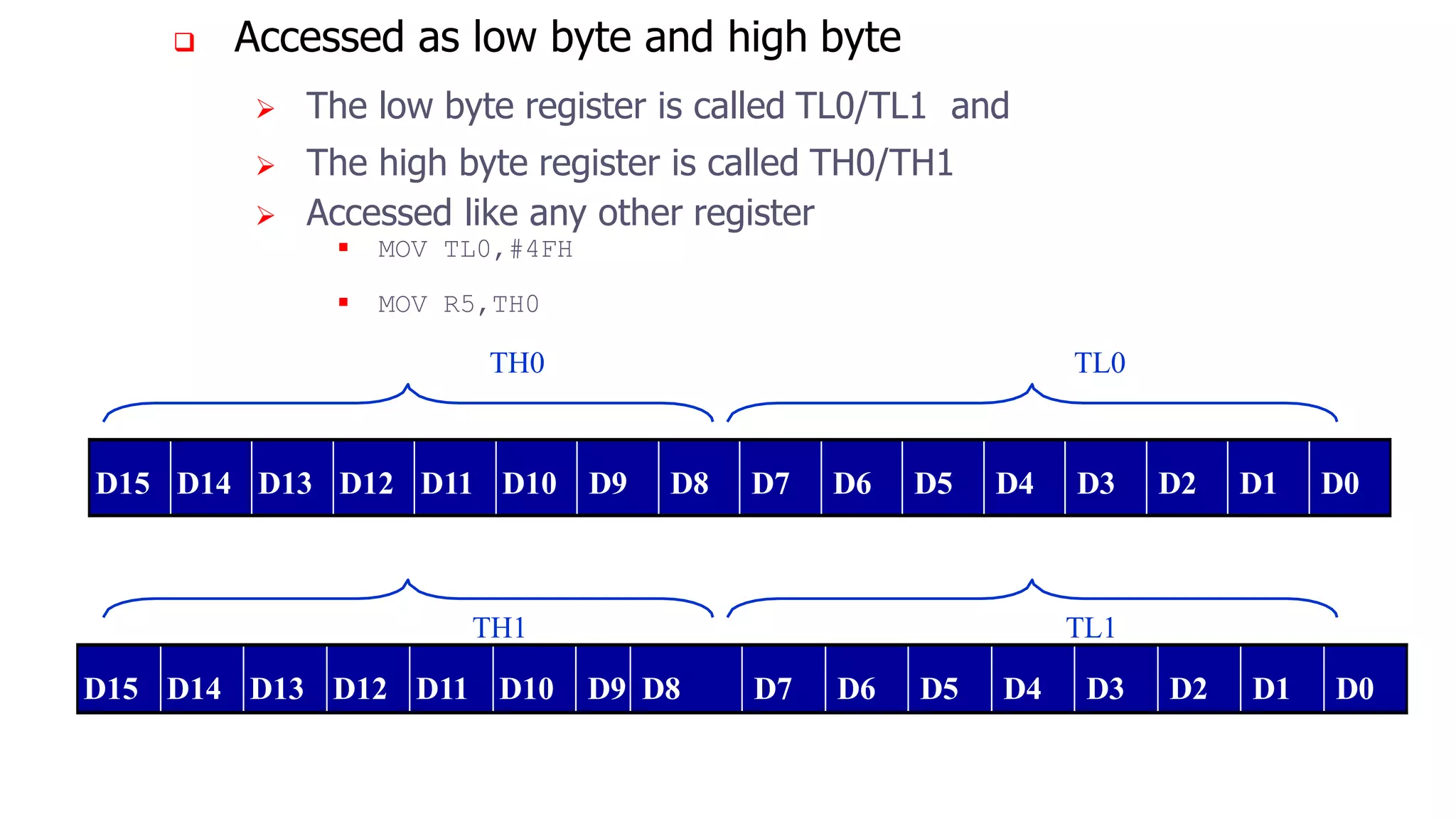
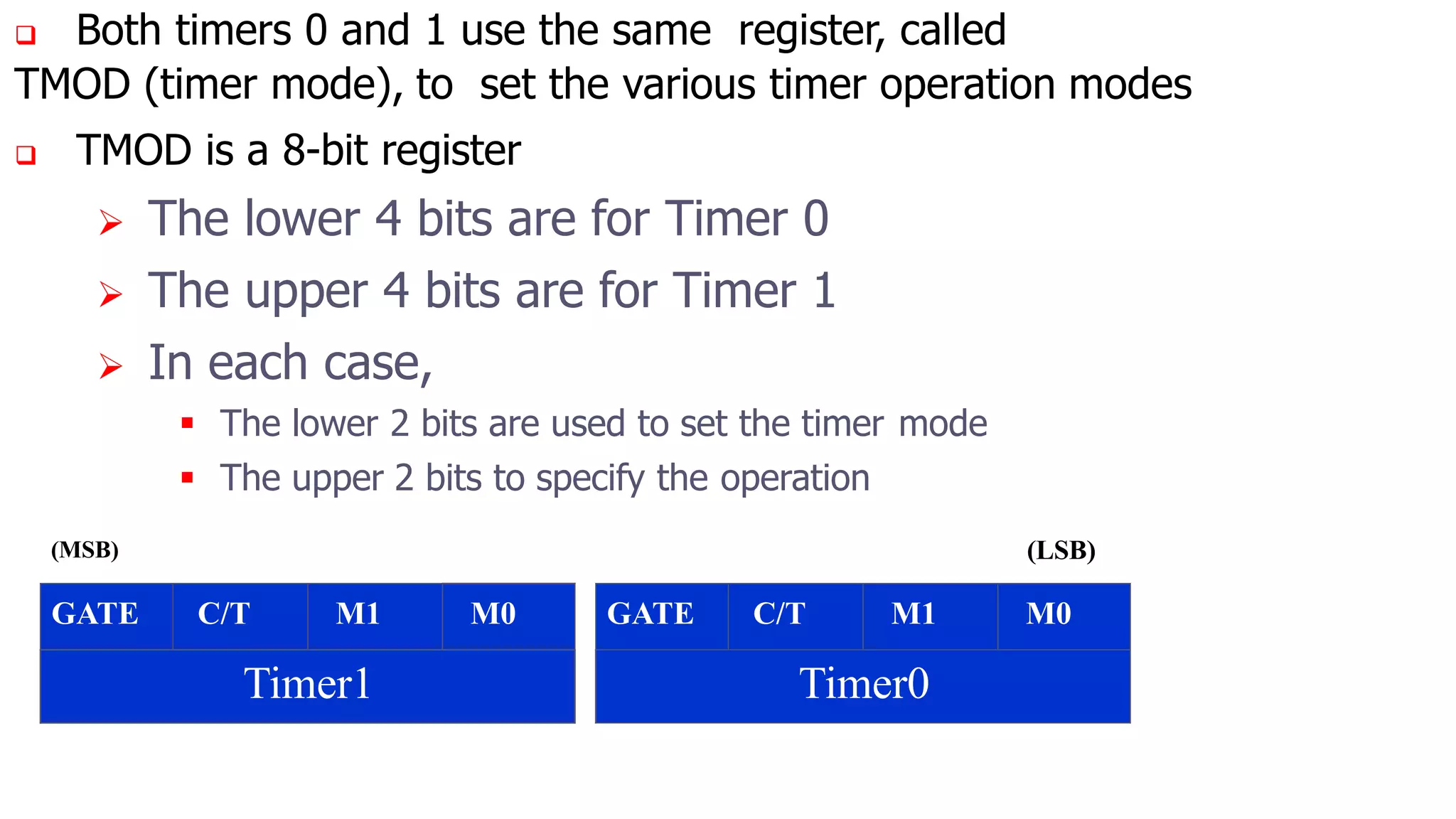
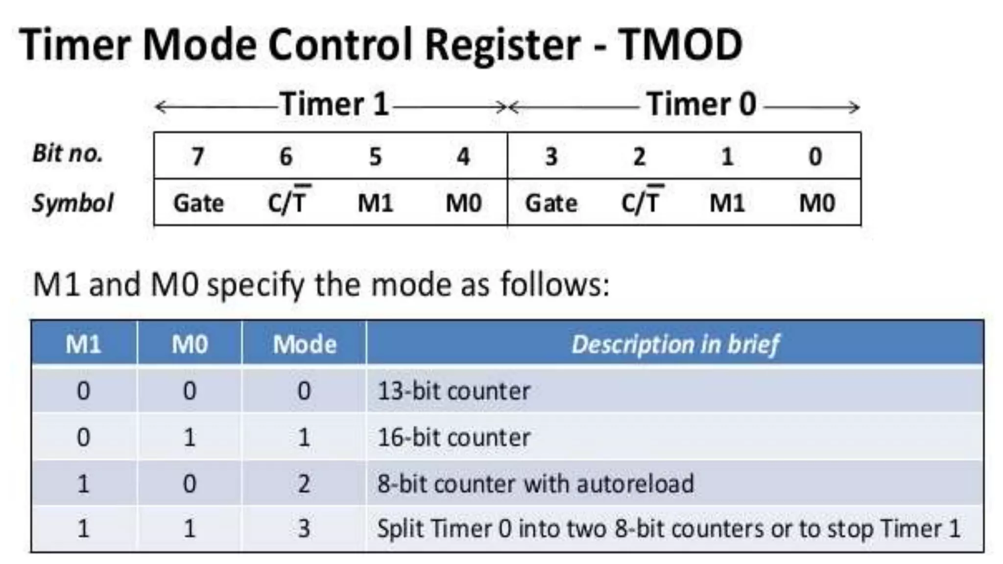

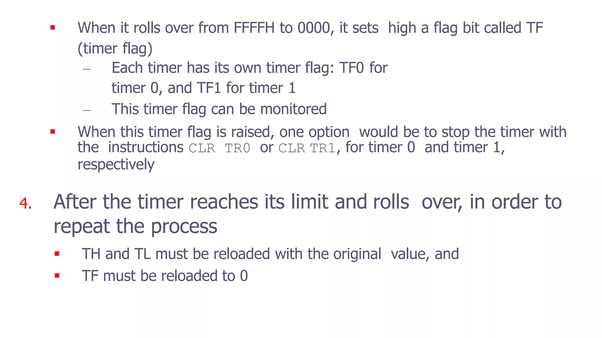
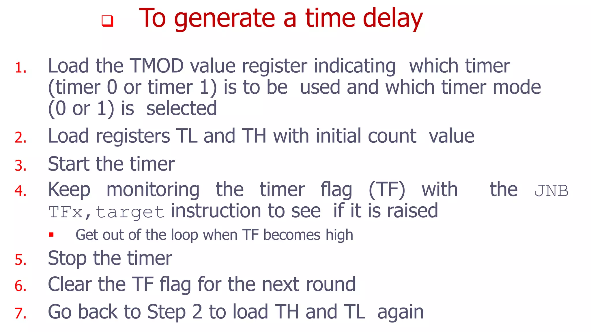

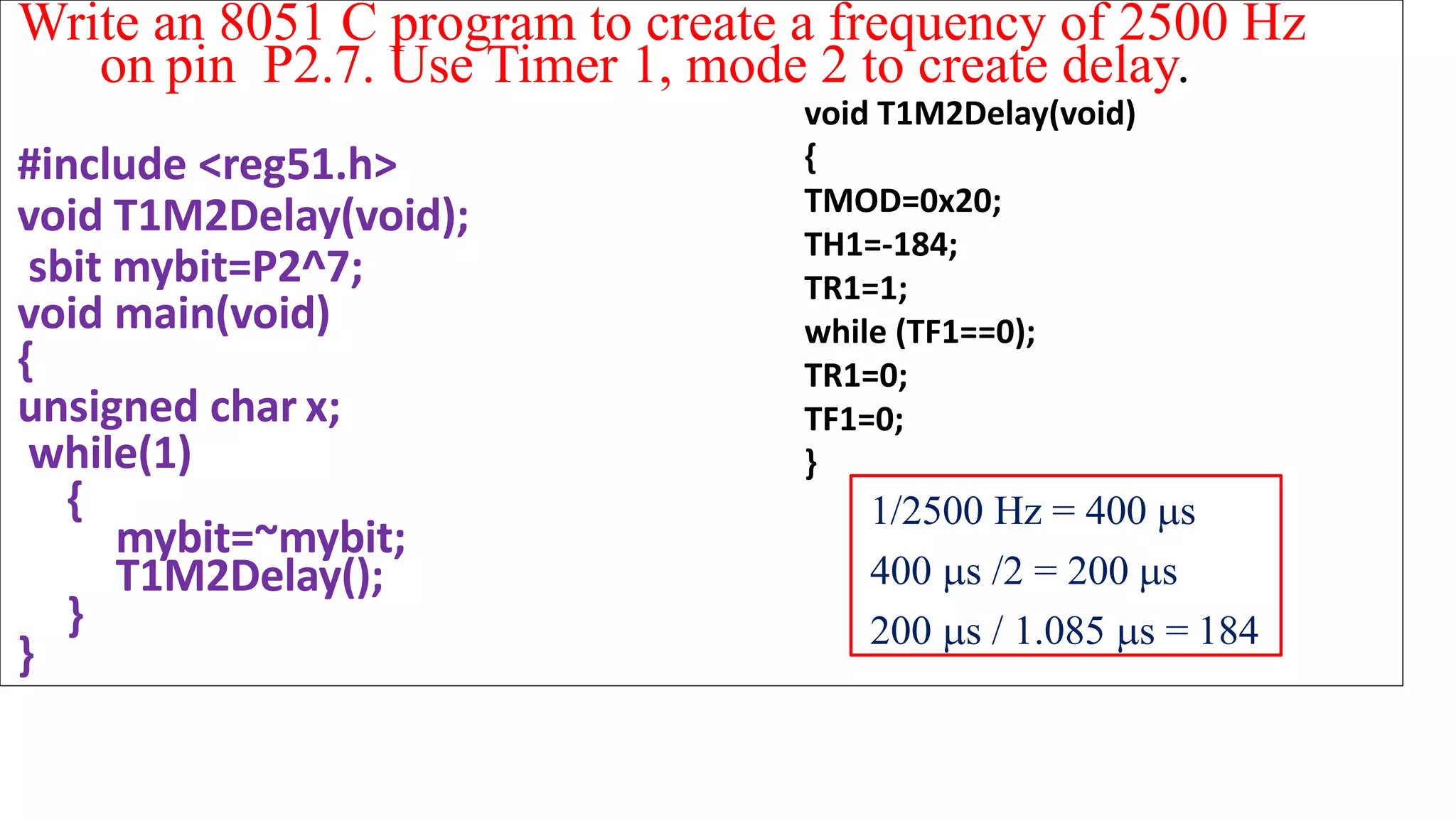
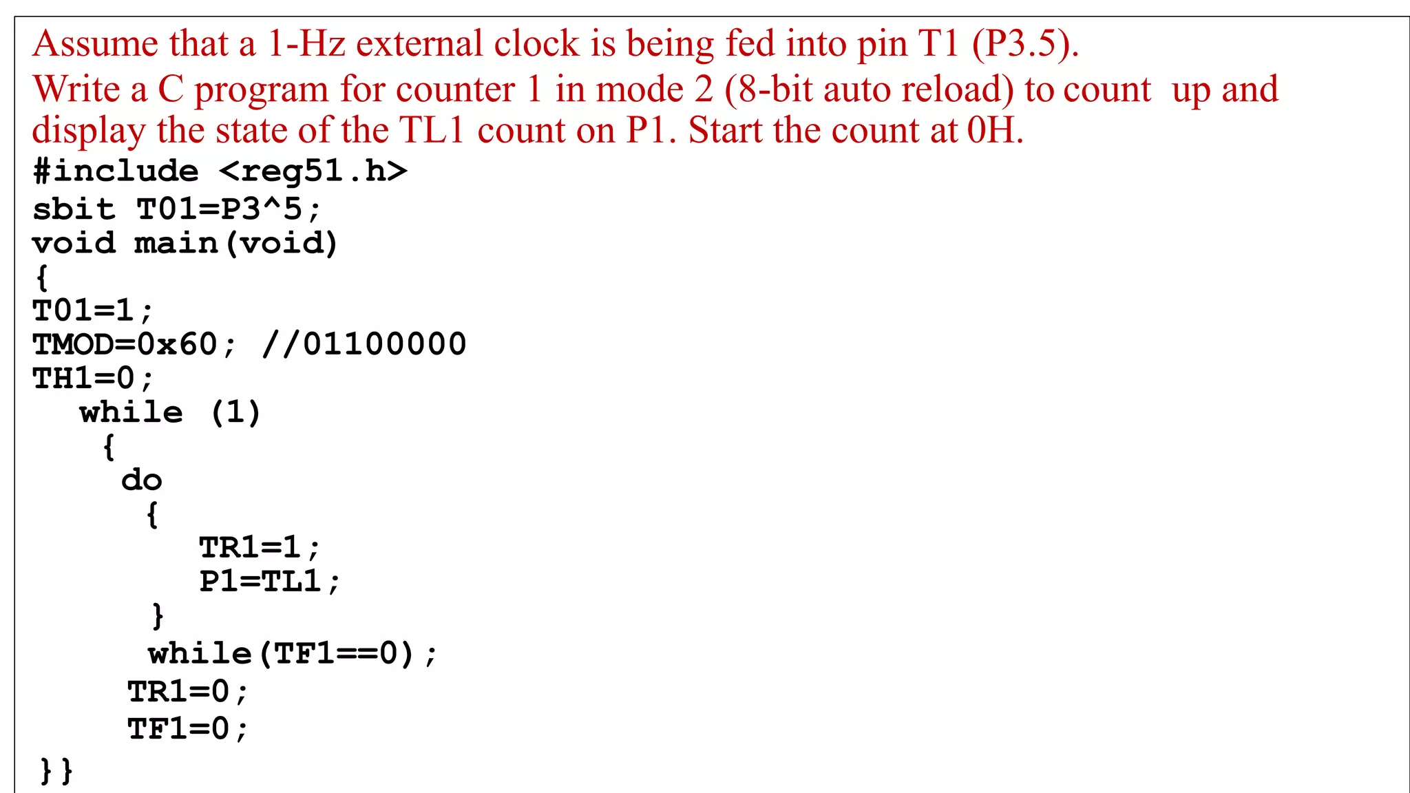


The document discusses the timers and counters of the 8051 microcontroller. It describes that the 8051 has two 16-bit timers/counters that can be used as timers to generate delays or as event counters. These timers are accessed as two 8-bit registers - a low byte register (TL0/TL1) and high byte register (TH0/TH1). It also explains the timer mode register TMOD and provides code examples to use the timers for generating delays and frequencies.


