Downloaded 86 times

![Simulation and Synthesis
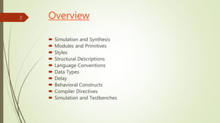
Simulation tools typically accept full set of Verilog
language constructs
Some language constructs and their use in a Verilog
description make simulation efficient and are ignored
by synthesis tools
Synthesis tools typically accept only a subset of the
full Verilog language constructs
In this presentation, Verilog language constructs not
supported in Synopsys FPGA Express are in red italics
There are other restrictions not detailed here, see [2].
3](https://image.slidesharecdn.com/verilog-151225073511/85/Verilog-Tutorial-Verilog-HDL-Tutorial-with-Examples-3-320.jpg)

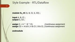
![Module Declaration
5
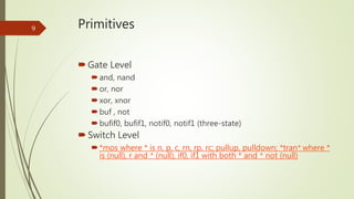
Annotated Example
/* module_keyword module_identifier (list of ports) */
module C_2_4_decoder_with_enable (A, E_n, D) ;
input [1:0] A ; // input_declaration
input E_n ; // input_declaration
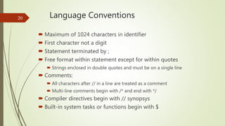
output [3:0] D ; // output_declaration
assign D = {4{~E_n}} & ((A == 2'b00) ? 4'b0001 :
(A == 2'b01) ? 4'b0010 :
(A == 2'b10) ? 4'b0100 :
(A == 2'b11) ? 4'b1000 :
4'bxxxx) ; // continuous_assign
endmodule](https://image.slidesharecdn.com/verilog-151225073511/85/Verilog-Tutorial-Verilog-HDL-Tutorial-with-Examples-5-320.jpg)
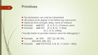
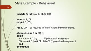
![Module Declaration
6
Identifiers - must not be keywords!
Ports
• First example of signals
• Scalar: e. g., E_n
• Vector: e. g., A[1:0], A[0:1], D[3:0], and D[0:3]
Range is MSB to LSB
Can refer to partial ranges - D[2:1]
• Type: defined by keywords
input
output
inout (bi-directional)](https://image.slidesharecdn.com/verilog-151225073511/85/Verilog-Tutorial-Verilog-HDL-Tutorial-with-Examples-6-320.jpg)
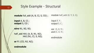
![Module Instantiation
7
module C_4_16_decoder_with_enable (A, E_n, D) ;
input [3:0] A ;
input E_n ;
output [15:0] D ;
wire [3:0] S;
wire [3:0] S_n;
C_2_4_decoder_with_enable DE (A[3:2], E_n, S);
not N0 (S_n, S);
C_2_4_decoder_with_enable D0 (A[1:0], S_n[0], D[3:0]);
C_2_4_decoder_with_enable D1 (A[1:0], S_n[1], D[7:4]);
C_2_4_decoder_with_enable D2 (A[1:0], S_n[2], D[11:8]);
C_2_4_decoder_with_enable D3 (A[1:0], S_n[3], D[15:12]);
endmodule
Example](https://image.slidesharecdn.com/verilog-151225073511/85/Verilog-Tutorial-Verilog-HDL-Tutorial-with-Examples-7-320.jpg)
![Module Instantiation
8
• Single module instantiation for five module instances
C_2_4_decoder_with_enable DE (A[3:2], E_n, S),
D0 (A[1:0], S_n[0], D[3:0]),
D1 (A[1:0], S_n[1], D[7:4]),
D2 (A[1:0], S_n[2], D[11:8]),
D3 (A[1:0], S_n[3], D[15:12]);
• Named_port connection
C_2_4_decoder_with_enable DE (.E_n (E_n), .A (A[3:2]) .D (S));
// Note order in list no longer important (E_n and A interchanged).
More Examples](https://image.slidesharecdn.com/verilog-151225073511/85/Verilog-Tutorial-Verilog-HDL-Tutorial-with-Examples-8-320.jpg)

![Connections
By position association
module C_2_4_decoder_with_enable (A, E_n, D);
C_4_16_decoder_with_enable DX (X[3:2], W_n, word);
A = X[3:2], E_n = W_n, D = word
By name association
module C_2_4_decoder_with_enable (A, E_n, D);
C_2_4_decoder_with_enable DX (.E_n(W_n), .A(X[3:2]),
.D(word));
A = X[3:2], E_n = W_n, D = word
16](https://image.slidesharecdn.com/verilog-151225073511/85/Verilog-Tutorial-Verilog-HDL-Tutorial-with-Examples-15-320.jpg)
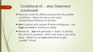
![Connections
Empty Port Connections
module C_2_4_decoder_with_enable (A, E_n, D);
C_2_4_decoder_with_enable DX (X[3:2], , word);
Input E_n is at high-impedance state (z)
C_2_4_decoder_with_enable DX (X[3:2], W_n ,);
Output D[3:0] unused.
17](https://image.slidesharecdn.com/verilog-151225073511/85/Verilog-Tutorial-Verilog-HDL-Tutorial-with-Examples-16-320.jpg)
![Arrays of Instances
{ , } is concatenate
Example
module add_array (A, B, CIN, S, COUT) ;
input [7:0] A, B ;
input CIN ;
output [7:0] S ;
output COUT ;
wire [7:1] carry;
full_add FA[7:0] (A,B,{carry, CIN},S,{COUT, carry});
// instantiates eight full_add modules
endmodule
18](https://image.slidesharecdn.com/verilog-151225073511/85/Verilog-Tutorial-Verilog-HDL-Tutorial-with-Examples-17-320.jpg)

![Net Examples
wire x;
wire x, y;
wire [15:0] data, address;
wire vectored [1:7] control;
wire address = offset + index;
wor interrupt_1, interrupt_2;
tri [31:0] data_bus, operand_bus;
Value implicitly assigned by connection to primitive or
module output
26](https://image.slidesharecdn.com/verilog-151225073511/85/Verilog-Tutorial-Verilog-HDL-Tutorial-with-Examples-25-320.jpg)

![Register Examples
reg a, b, c;
reg [15:0] counter, shift_reg;
reg [8:4] flops;
integer sum, difference;
30](https://image.slidesharecdn.com/verilog-151225073511/85/Verilog-Tutorial-Verilog-HDL-Tutorial-with-Examples-29-320.jpg)
![Strings
No explicit data type
Must be stored in reg whose size is 8*(num. of characters)
reg [255:0] buffer; //stores 32 characters
31](https://image.slidesharecdn.com/verilog-151225073511/85/Verilog-Tutorial-Verilog-HDL-Tutorial-with-Examples-30-320.jpg)
![Constants (Paramters)
Declaration of parameters
parameter A = 2’b00, B = 2’b01, C = 2’b10;
parameter regsize = 8;
reg [regsize - 1:0]; /* illustrates use of parameter regsize */
32](https://image.slidesharecdn.com/verilog-151225073511/85/Verilog-Tutorial-Verilog-HDL-Tutorial-with-Examples-31-320.jpg)
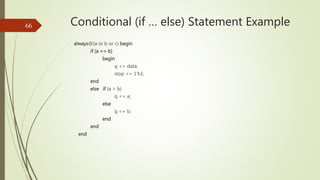
![case Statement
Requires complete bitwise match over all four values so
expression and case item expression must have same bit
length
Example: always@(state, x) begin
reg[1:0] state;
case (state)
2’b00: next_state <= s1;
2’b01: next_state <= s2;
2’b10: if x next_state <= s0;
else next_state <= s1;
end
default next_state = 1’bxx;
endcase
end
63](https://image.slidesharecdn.com/verilog-151225073511/85/Verilog-Tutorial-Verilog-HDL-Tutorial-with-Examples-62-320.jpg)
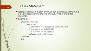
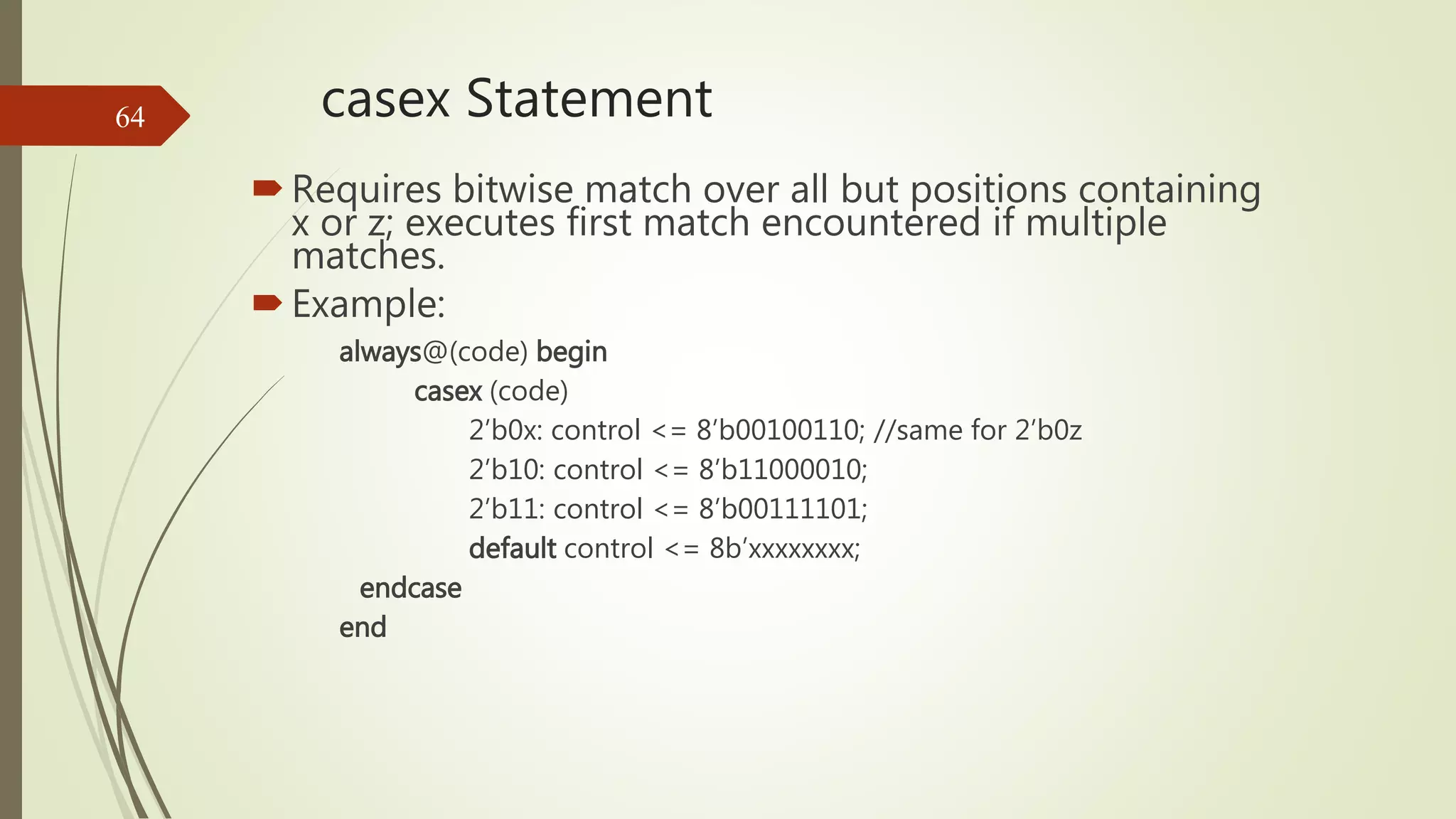
![casez Statement
Requires bitwise match over all but positions containing
z or ? (? is explicit don’t care); executes first match
encountered if multiple matches.
Example:
reg [1:0] code;
always@(code) begin
casez (code)
2’b0z: control <= 8’b00100110;
2’b1?: control <= 8’b11000010;
default control <= 8b’xxxxxxxx;
endcase
end
65](https://image.slidesharecdn.com/verilog-151225073511/85/Verilog-Tutorial-Verilog-HDL-Tutorial-with-Examples-64-320.jpg)
![for Loop Example
Example:
initial
integer r, i;
begin
r = 0;
for (i = 1; i <= 7; i = i + 2)
begin
r[i] = 1;
end
end
68](https://image.slidesharecdn.com/verilog-151225073511/85/Verilog-Tutorial-Verilog-HDL-Tutorial-with-Examples-67-320.jpg)
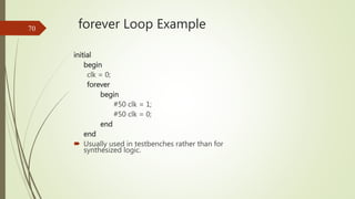
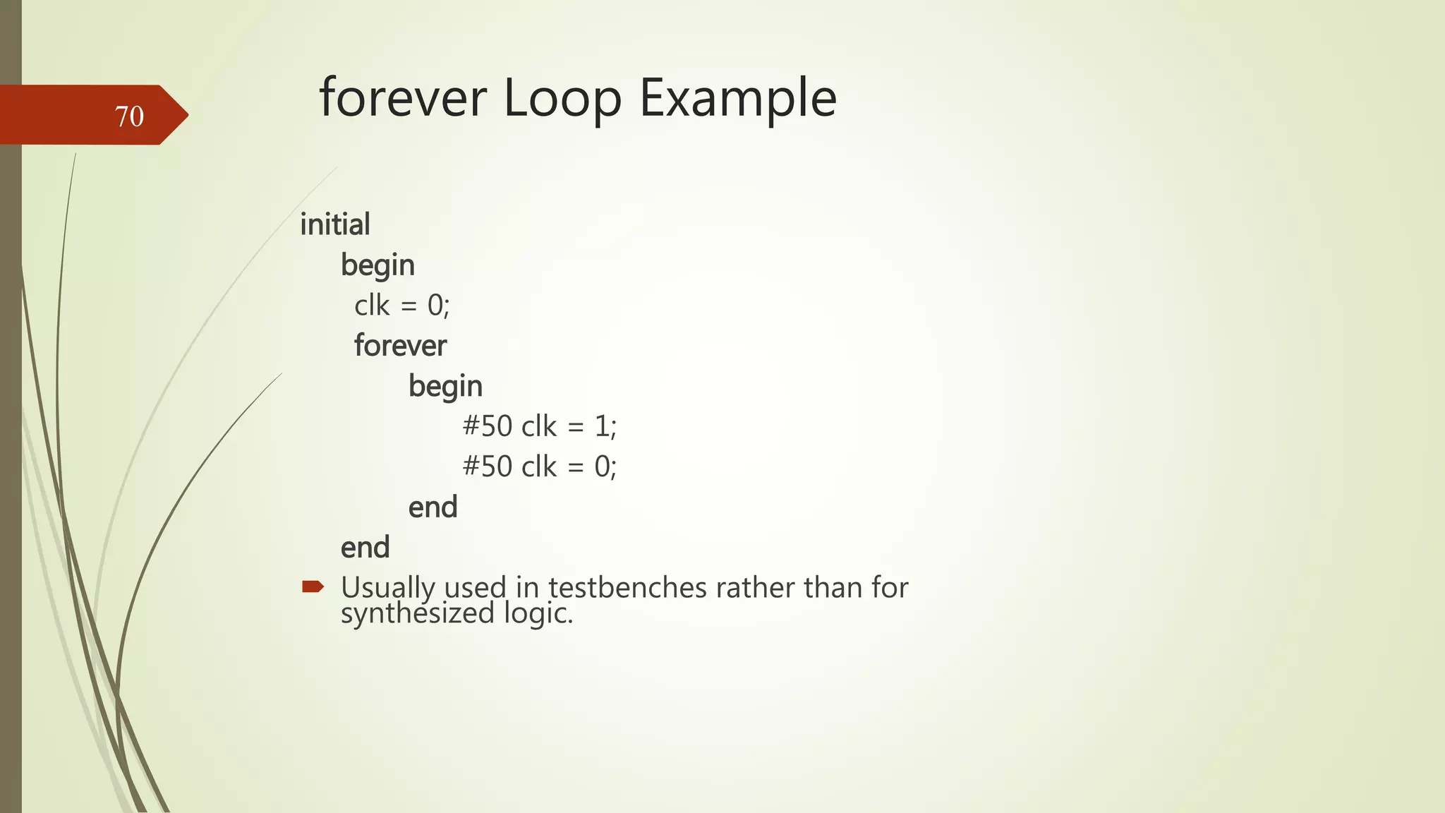
![while Loop Example
initial
begin
r = 0;
i = 0;
while (i <= 7)
begin
r[i] = 1;
i = i + 2;
end
end
69](https://image.slidesharecdn.com/verilog-151225073511/85/Verilog-Tutorial-Verilog-HDL-Tutorial-with-Examples-68-320.jpg)
![Tasks
Declared within a module
Referenced only by a behavior within the module
Parameters passed to task as inputs and inouts and
from task as outputs or inouts
Local variables can be declared
Recursion not supported although nesting permitted
(nested copies of variables use same storage)
See Fig. 7.43 p. 226 of [5]for rules
71](https://image.slidesharecdn.com/verilog-151225073511/85/Verilog-Tutorial-Verilog-HDL-Tutorial-with-Examples-70-320.jpg)
![Task Example
task leading_1;
input [7:0] data_word;
output [2:0] position;
reg [7:0] temp;
reg [2:0] position;
begin
temp = data_word;
position = 3'b111;
while (!temp[7])
@(posedge clock)
begin
temp = temp << 1;
position = position - 1;
end
end
endtask // Code is not synthesizable
72](https://image.slidesharecdn.com/verilog-151225073511/85/Verilog-Tutorial-Verilog-HDL-Tutorial-with-Examples-71-320.jpg)
![Function Example
function [2:0] leading_1;
input [7:0] data_word;
reg [7:0] temp;
begin
temp = data_word;
leading_1 = 3'b111;
while (!temp[7])
begin
temp = temp << 1;
leading_1 = leading_1 - 1;
end
end
endfunction
Is the above code synthesizable?
74
No](https://image.slidesharecdn.com/verilog-151225073511/85/Verilog-Tutorial-Verilog-HDL-Tutorial-with-Examples-73-320.jpg)
![Stimulus Generation Example
`timescale 1ns /1ns
module com_test_bench_v;
reg[8:0] stim;
wire[3:0] S;
wire C4;
adder_4_b_v a1(stim[8:5], stim[4:1], stim[0], S, C4);
//Continued on next slide
endmodule
78](https://image.slidesharecdn.com/verilog-151225073511/85/Verilog-Tutorial-Verilog-HDL-Tutorial-with-Examples-77-320.jpg)
![Simulation and Synthesis
Simulation tools typically accept full set of Verilog
language constructs
Some language constructs and their use in a Verilog
description make simulation efficient and are ignored
by synthesis tools
Synthesis tools typically accept only a subset of the
full Verilog language constructs
In this presentation, Verilog language constructs not
supported in Synopsys FPGA Express are in red italics
There are other restrictions not detailed here, see [2].
3](https://image.slidesharecdn.com/verilog-151225073511/75/Verilog-Tutorial-Verilog-HDL-Tutorial-with-Examples-3-2048.jpg)
![Module Declaration
5
Annotated Example
/* module_keyword module_identifier (list of ports) */
module C_2_4_decoder_with_enable (A, E_n, D) ;
input [1:0] A ; // input_declaration
input E_n ; // input_declaration
output [3:0] D ; // output_declaration
assign D = {4{~E_n}} & ((A == 2'b00) ? 4'b0001 :
(A == 2'b01) ? 4'b0010 :
(A == 2'b10) ? 4'b0100 :
(A == 2'b11) ? 4'b1000 :
4'bxxxx) ; // continuous_assign
endmodule](https://image.slidesharecdn.com/verilog-151225073511/75/Verilog-Tutorial-Verilog-HDL-Tutorial-with-Examples-5-2048.jpg)
![Module Declaration
6
Identifiers - must not be keywords!
Ports
• First example of signals
• Scalar: e. g., E_n
• Vector: e. g., A[1:0], A[0:1], D[3:0], and D[0:3]
Range is MSB to LSB
Can refer to partial ranges - D[2:1]
• Type: defined by keywords
input
output
inout (bi-directional)](https://image.slidesharecdn.com/verilog-151225073511/75/Verilog-Tutorial-Verilog-HDL-Tutorial-with-Examples-6-2048.jpg)
![Module Instantiation
7
module C_4_16_decoder_with_enable (A, E_n, D) ;
input [3:0] A ;
input E_n ;
output [15:0] D ;
wire [3:0] S;
wire [3:0] S_n;
C_2_4_decoder_with_enable DE (A[3:2], E_n, S);
not N0 (S_n, S);
C_2_4_decoder_with_enable D0 (A[1:0], S_n[0], D[3:0]);
C_2_4_decoder_with_enable D1 (A[1:0], S_n[1], D[7:4]);
C_2_4_decoder_with_enable D2 (A[1:0], S_n[2], D[11:8]);
C_2_4_decoder_with_enable D3 (A[1:0], S_n[3], D[15:12]);
endmodule
Example](https://image.slidesharecdn.com/verilog-151225073511/75/Verilog-Tutorial-Verilog-HDL-Tutorial-with-Examples-7-2048.jpg)
![Module Instantiation
8
• Single module instantiation for five module instances
C_2_4_decoder_with_enable DE (A[3:2], E_n, S),
D0 (A[1:0], S_n[0], D[3:0]),
D1 (A[1:0], S_n[1], D[7:4]),
D2 (A[1:0], S_n[2], D[11:8]),
D3 (A[1:0], S_n[3], D[15:12]);
• Named_port connection
C_2_4_decoder_with_enable DE (.E_n (E_n), .A (A[3:2]) .D (S));
// Note order in list no longer important (E_n and A interchanged).
More Examples](https://image.slidesharecdn.com/verilog-151225073511/75/Verilog-Tutorial-Verilog-HDL-Tutorial-with-Examples-8-2048.jpg)
![Connections
By position association
module C_2_4_decoder_with_enable (A, E_n, D);
C_4_16_decoder_with_enable DX (X[3:2], W_n, word);
A = X[3:2], E_n = W_n, D = word
By name association
module C_2_4_decoder_with_enable (A, E_n, D);
C_2_4_decoder_with_enable DX (.E_n(W_n), .A(X[3:2]),
.D(word));
A = X[3:2], E_n = W_n, D = word
16](https://image.slidesharecdn.com/verilog-151225073511/75/Verilog-Tutorial-Verilog-HDL-Tutorial-with-Examples-15-2048.jpg)
![Connections
Empty Port Connections
module C_2_4_decoder_with_enable (A, E_n, D);
C_2_4_decoder_with_enable DX (X[3:2], , word);
Input E_n is at high-impedance state (z)
C_2_4_decoder_with_enable DX (X[3:2], W_n ,);
Output D[3:0] unused.
17](https://image.slidesharecdn.com/verilog-151225073511/75/Verilog-Tutorial-Verilog-HDL-Tutorial-with-Examples-16-2048.jpg)
![Arrays of Instances
{ , } is concatenate
Example
module add_array (A, B, CIN, S, COUT) ;
input [7:0] A, B ;
input CIN ;
output [7:0] S ;
output COUT ;
wire [7:1] carry;
full_add FA[7:0] (A,B,{carry, CIN},S,{COUT, carry});
// instantiates eight full_add modules
endmodule
18](https://image.slidesharecdn.com/verilog-151225073511/75/Verilog-Tutorial-Verilog-HDL-Tutorial-with-Examples-17-2048.jpg)

![Net Examples
wire x;
wire x, y;
wire [15:0] data, address;
wire vectored [1:7] control;
wire address = offset + index;
wor interrupt_1, interrupt_2;
tri [31:0] data_bus, operand_bus;
Value implicitly assigned by connection to primitive or
module output
26](https://image.slidesharecdn.com/verilog-151225073511/75/Verilog-Tutorial-Verilog-HDL-Tutorial-with-Examples-25-2048.jpg)
![Register Examples
reg a, b, c;
reg [15:0] counter, shift_reg;
reg [8:4] flops;
integer sum, difference;
30](https://image.slidesharecdn.com/verilog-151225073511/75/Verilog-Tutorial-Verilog-HDL-Tutorial-with-Examples-29-2048.jpg)
![Strings
No explicit data type
Must be stored in reg whose size is 8*(num. of characters)
reg [255:0] buffer; //stores 32 characters
31](https://image.slidesharecdn.com/verilog-151225073511/75/Verilog-Tutorial-Verilog-HDL-Tutorial-with-Examples-30-2048.jpg)
![Constants (Paramters)
Declaration of parameters
parameter A = 2’b00, B = 2’b01, C = 2’b10;
parameter regsize = 8;
reg [regsize - 1:0]; /* illustrates use of parameter regsize */
32](https://image.slidesharecdn.com/verilog-151225073511/75/Verilog-Tutorial-Verilog-HDL-Tutorial-with-Examples-31-2048.jpg)
![case Statement
Requires complete bitwise match over all four values so
expression and case item expression must have same bit
length
Example: always@(state, x) begin
reg[1:0] state;
case (state)
2’b00: next_state <= s1;
2’b01: next_state <= s2;
2’b10: if x next_state <= s0;
else next_state <= s1;
end
default next_state = 1’bxx;
endcase
end
63](https://image.slidesharecdn.com/verilog-151225073511/75/Verilog-Tutorial-Verilog-HDL-Tutorial-with-Examples-62-2048.jpg)
![casez Statement
Requires bitwise match over all but positions containing
z or ? (? is explicit don’t care); executes first match
encountered if multiple matches.
Example:
reg [1:0] code;
always@(code) begin
casez (code)
2’b0z: control <= 8’b00100110;
2’b1?: control <= 8’b11000010;
default control <= 8b’xxxxxxxx;
endcase
end
65](https://image.slidesharecdn.com/verilog-151225073511/75/Verilog-Tutorial-Verilog-HDL-Tutorial-with-Examples-64-2048.jpg)
![for Loop Example
Example:
initial
integer r, i;
begin
r = 0;
for (i = 1; i <= 7; i = i + 2)
begin
r[i] = 1;
end
end
68](https://image.slidesharecdn.com/verilog-151225073511/75/Verilog-Tutorial-Verilog-HDL-Tutorial-with-Examples-67-2048.jpg)
![while Loop Example
initial
begin
r = 0;
i = 0;
while (i <= 7)
begin
r[i] = 1;
i = i + 2;
end
end
69](https://image.slidesharecdn.com/verilog-151225073511/75/Verilog-Tutorial-Verilog-HDL-Tutorial-with-Examples-68-2048.jpg)
![Tasks
Declared within a module
Referenced only by a behavior within the module
Parameters passed to task as inputs and inouts and
from task as outputs or inouts
Local variables can be declared
Recursion not supported although nesting permitted
(nested copies of variables use same storage)
See Fig. 7.43 p. 226 of [5]for rules
71](https://image.slidesharecdn.com/verilog-151225073511/75/Verilog-Tutorial-Verilog-HDL-Tutorial-with-Examples-70-2048.jpg)
![Task Example
task leading_1;
input [7:0] data_word;
output [2:0] position;
reg [7:0] temp;
reg [2:0] position;
begin
temp = data_word;
position = 3'b111;
while (!temp[7])
@(posedge clock)
begin
temp = temp << 1;
position = position - 1;
end
end
endtask // Code is not synthesizable
72](https://image.slidesharecdn.com/verilog-151225073511/75/Verilog-Tutorial-Verilog-HDL-Tutorial-with-Examples-71-2048.jpg)
![Function Example
function [2:0] leading_1;
input [7:0] data_word;
reg [7:0] temp;
begin
temp = data_word;
leading_1 = 3'b111;
while (!temp[7])
begin
temp = temp << 1;
leading_1 = leading_1 - 1;
end
end
endfunction
Is the above code synthesizable?
74
No](https://image.slidesharecdn.com/verilog-151225073511/75/Verilog-Tutorial-Verilog-HDL-Tutorial-with-Examples-73-2048.jpg)
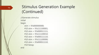
![Stimulus Generation Example
`timescale 1ns /1ns
module com_test_bench_v;
reg[8:0] stim;
wire[3:0] S;
wire C4;
adder_4_b_v a1(stim[8:5], stim[4:1], stim[0], S, C4);
//Continued on next slide
endmodule
78](https://image.slidesharecdn.com/verilog-151225073511/75/Verilog-Tutorial-Verilog-HDL-Tutorial-with-Examples-77-2048.jpg)

The document provides a comprehensive tutorial on Verilog HDL, covering crucial aspects such as simulation, synthesis, modules, and various language constructs. It includes structured examples of module declarations, instantiations, and data types, as well as language conventions and simulation time scales. Essential concepts such as signal values, operators, and expression bit widths are also discussed in detail.
Introduces Verilog HDL and E2MATRIX RESEARCH LAB with contact information.
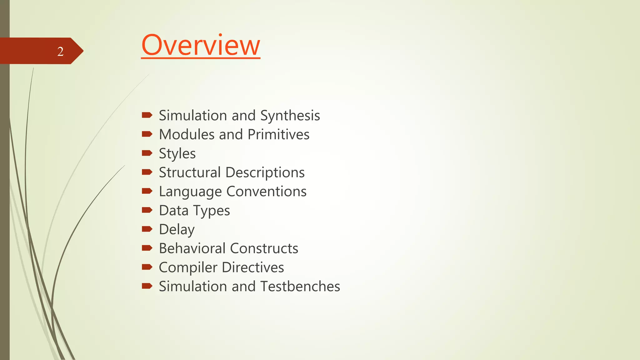
Covers key topics in Verilog including synthesis, modules, data types, delays, and language conventions.
Discusses the use of Verilog constructs in simulation and synthesis, highlighting which constructs are supported.
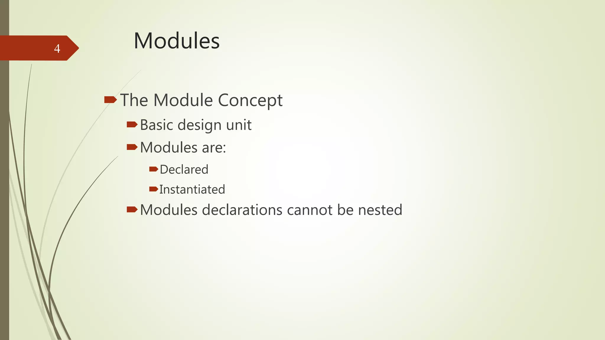
Explains the module concept as a basic design unit, emphasizing declaration and instantiation.
Details on module declaration syntax including identifiers, input/output ports, and their types.
Examples of module instantiation in Verilog, showcasing both single and named port connections.
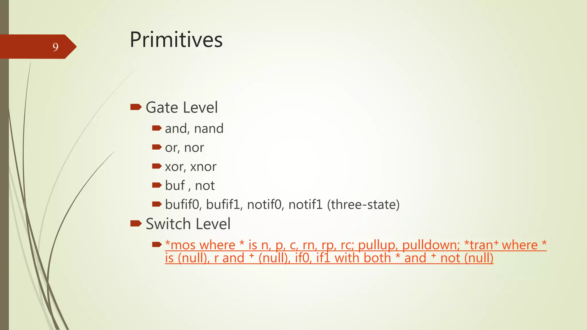
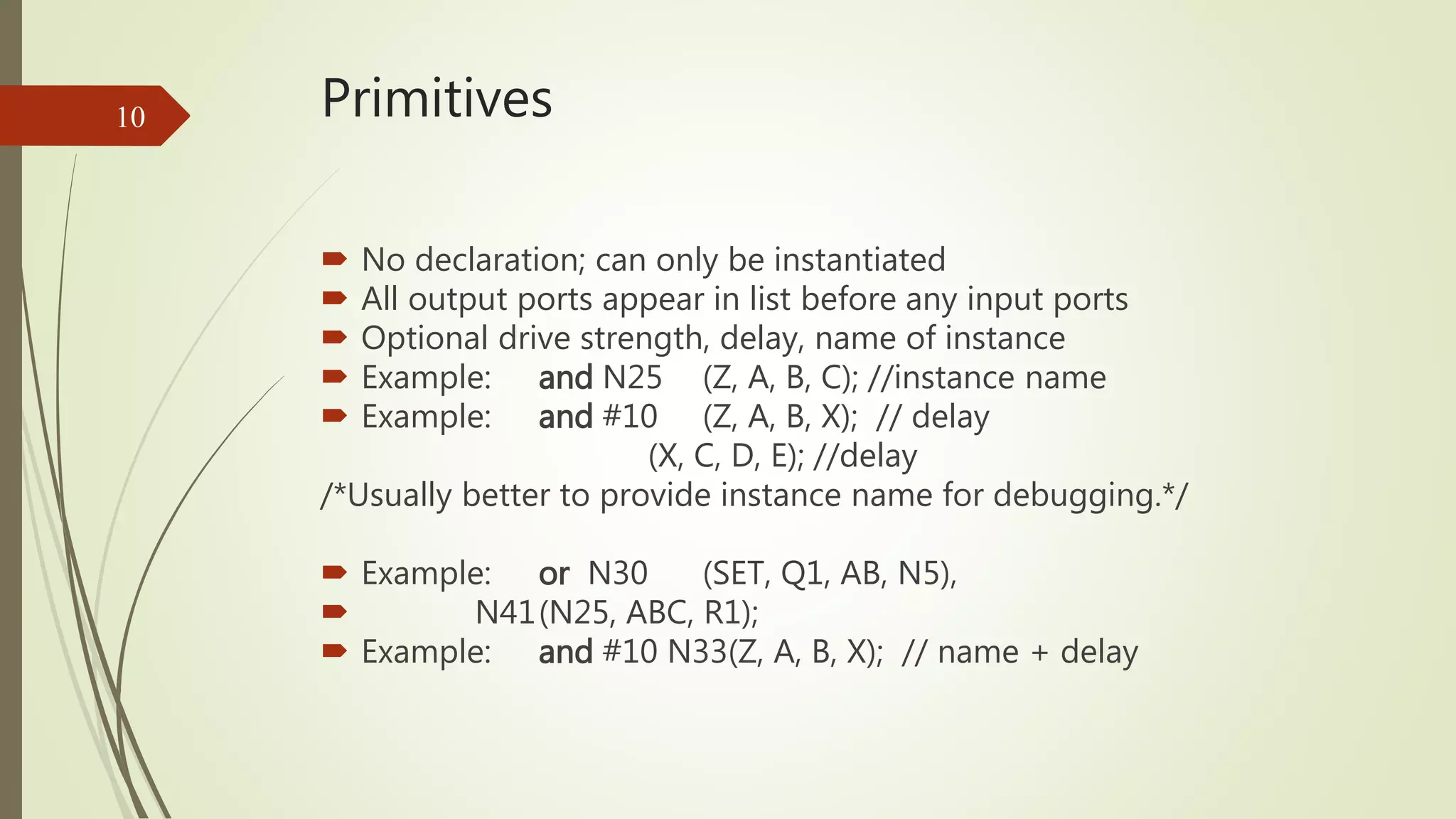
Introduces Verilog primitives, their instantiation, and the declaration requirements for different gate types.
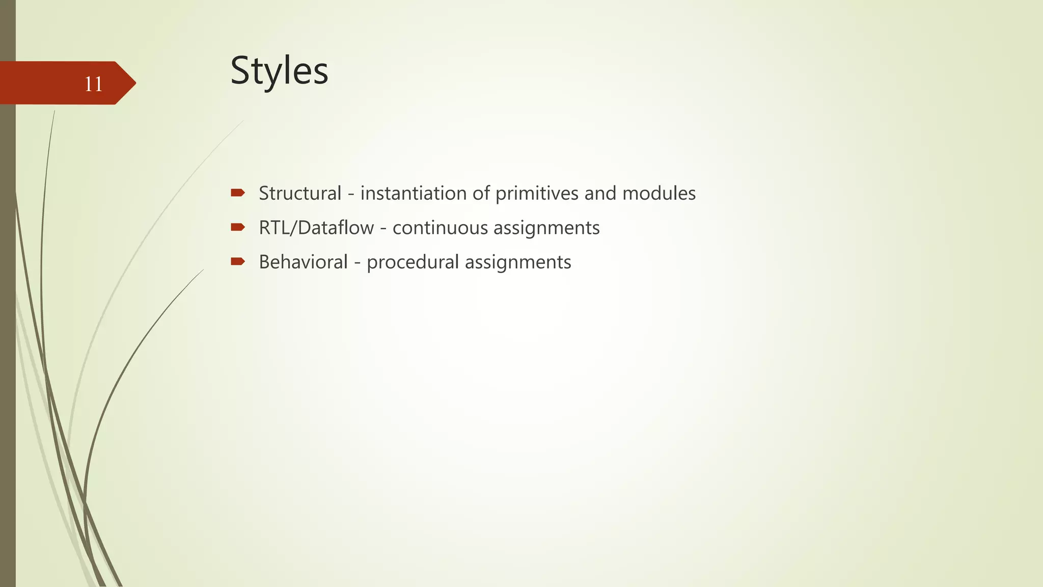
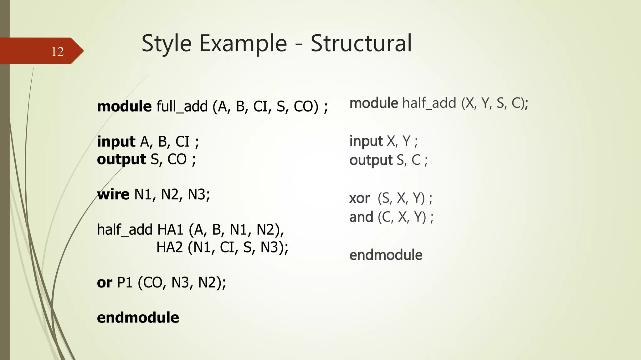
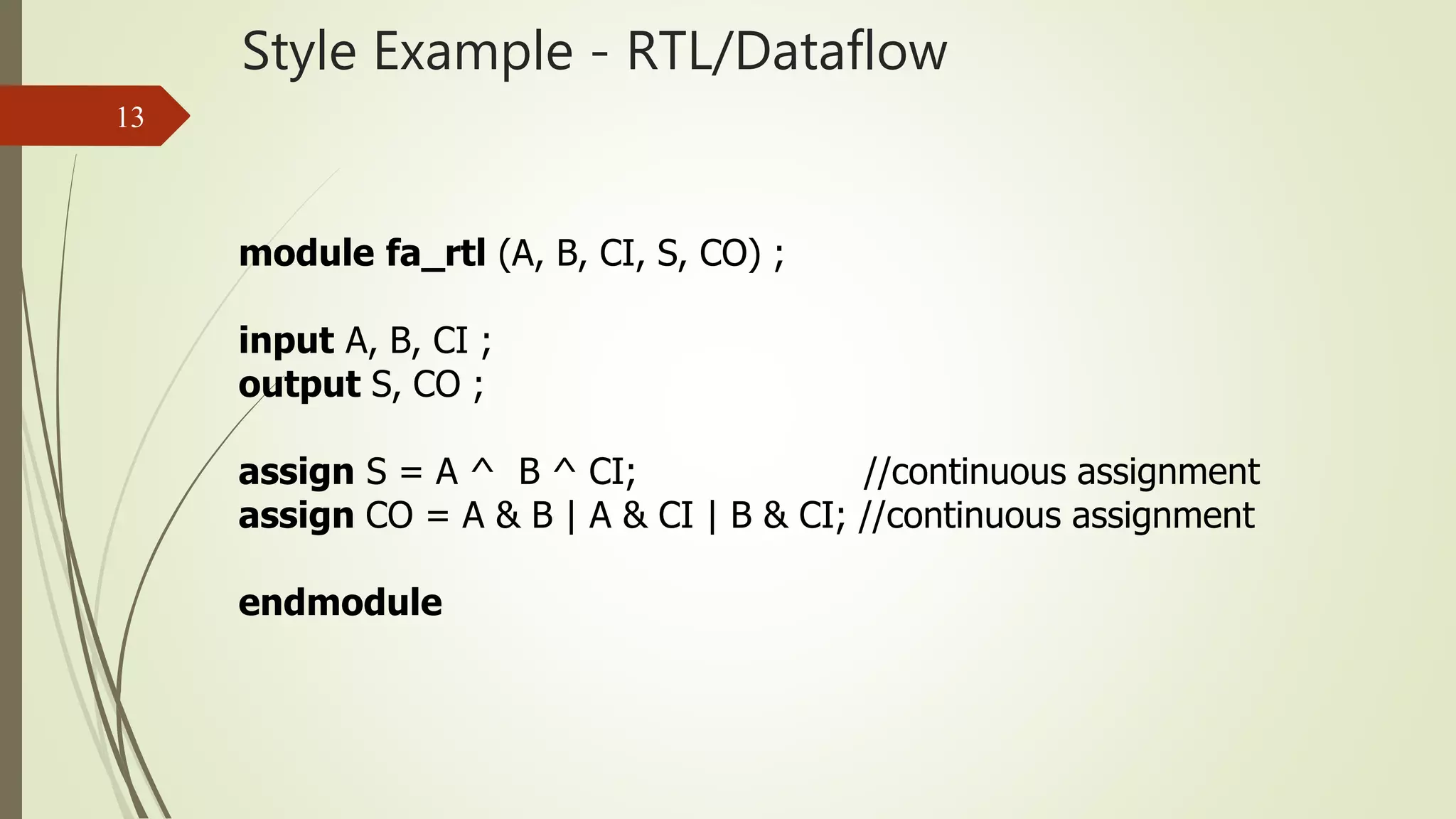
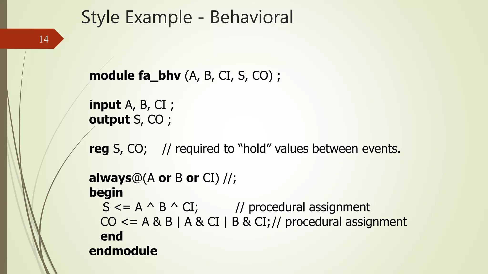
Describes structural, RTL/dataflow, and behavioral styles with examples of half and full adders.
Provides examples of RTL and behavioral modeling, highlighting procedural and continuous assignments.
Details on position and name association in module connections, including handling empty connections.
Explains the use of array instances for instantiating multiple modules efficiently.
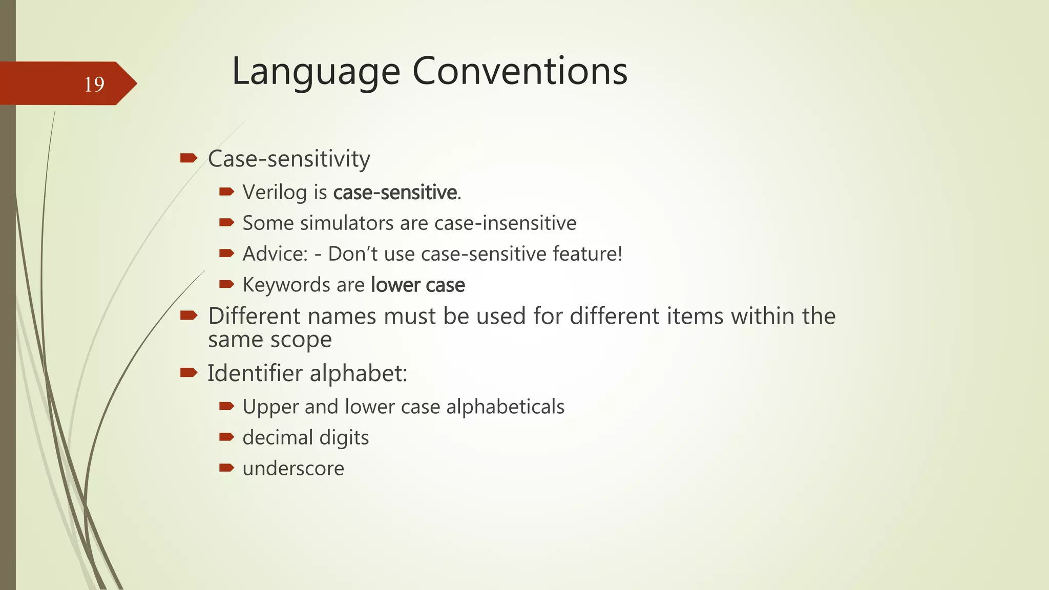
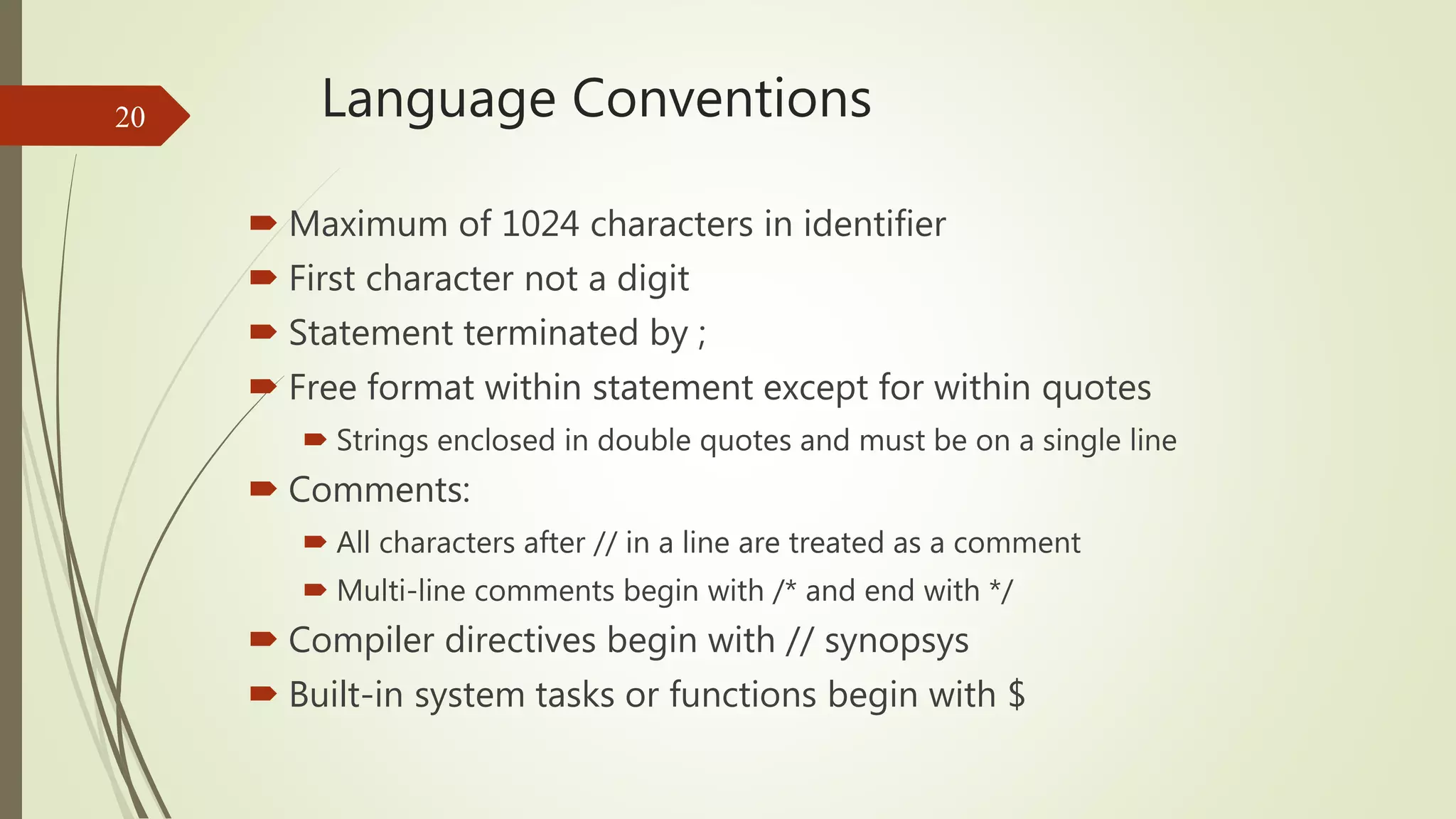
Details case sensitivity, maximum identifier lengths, comments, and syntax rules for Verilog.
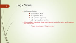
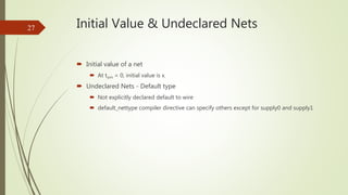
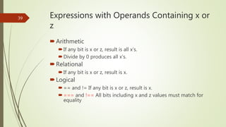
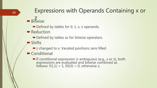
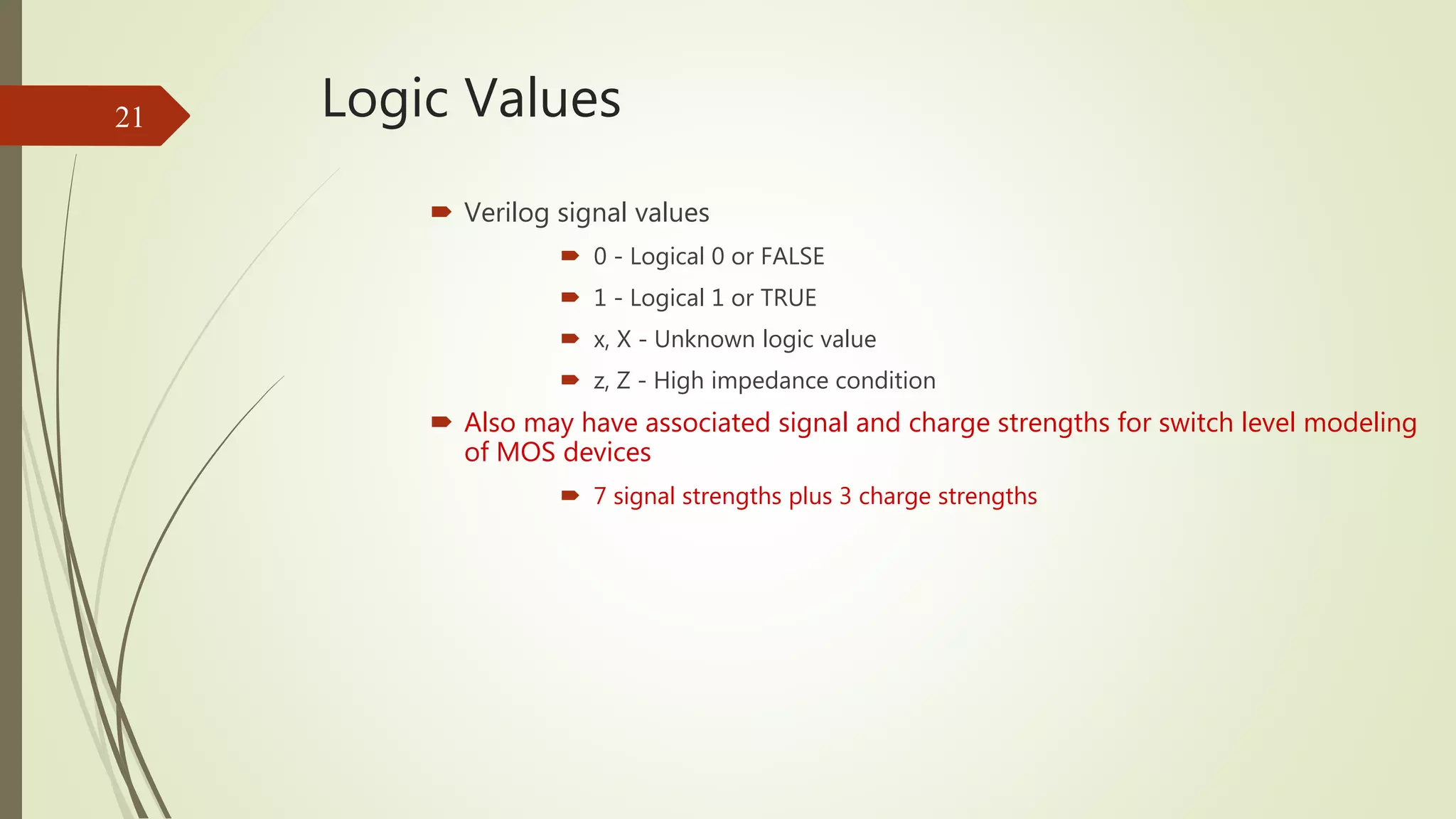
Describes signal values in Verilog including logical states and special logic values.
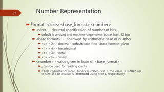
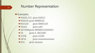
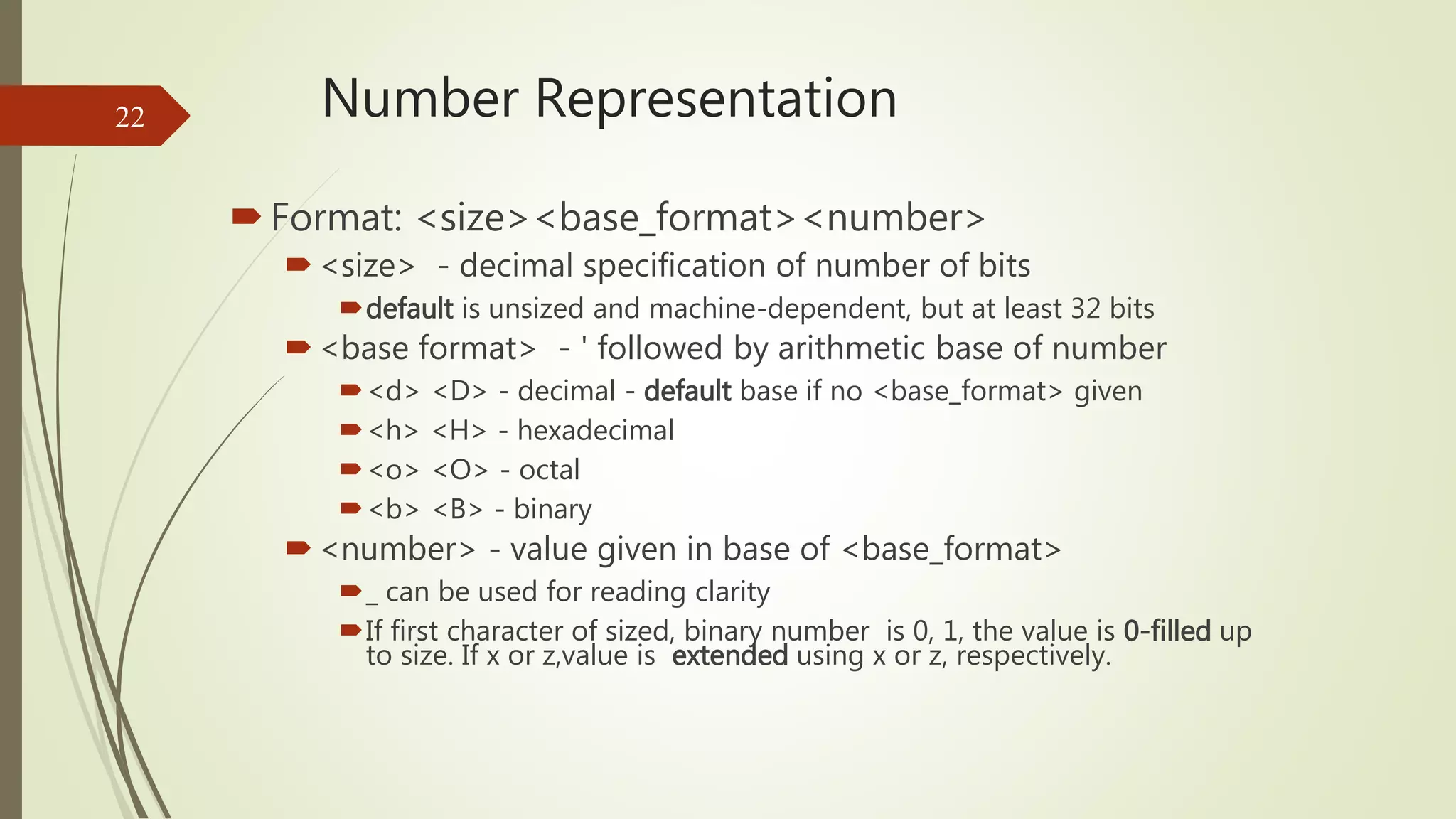
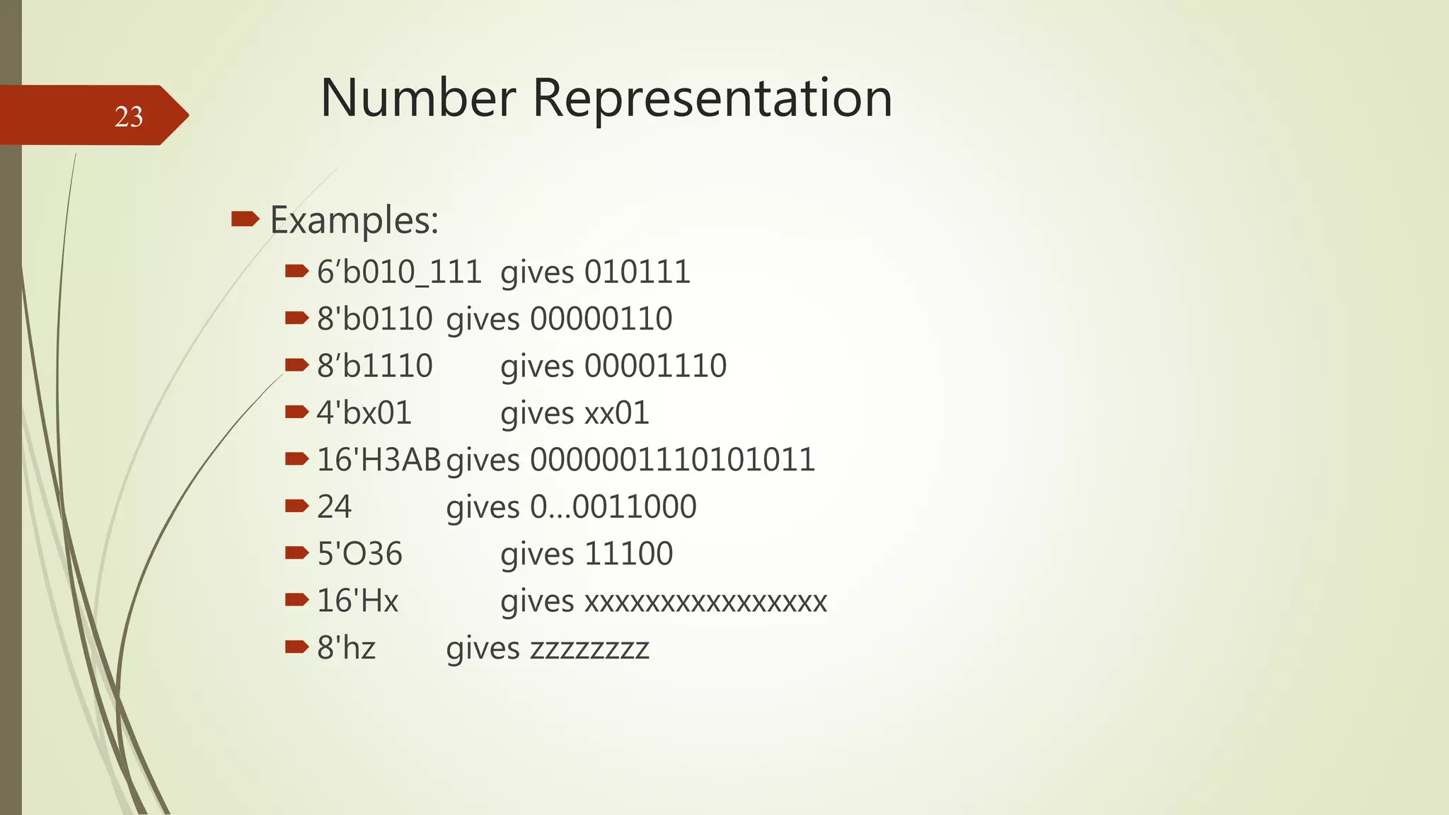
Explains how numbers are represented in Verilog including various formats and examples.
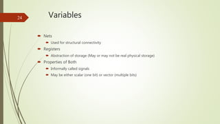
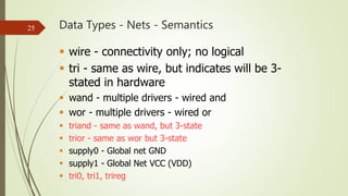
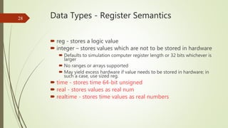
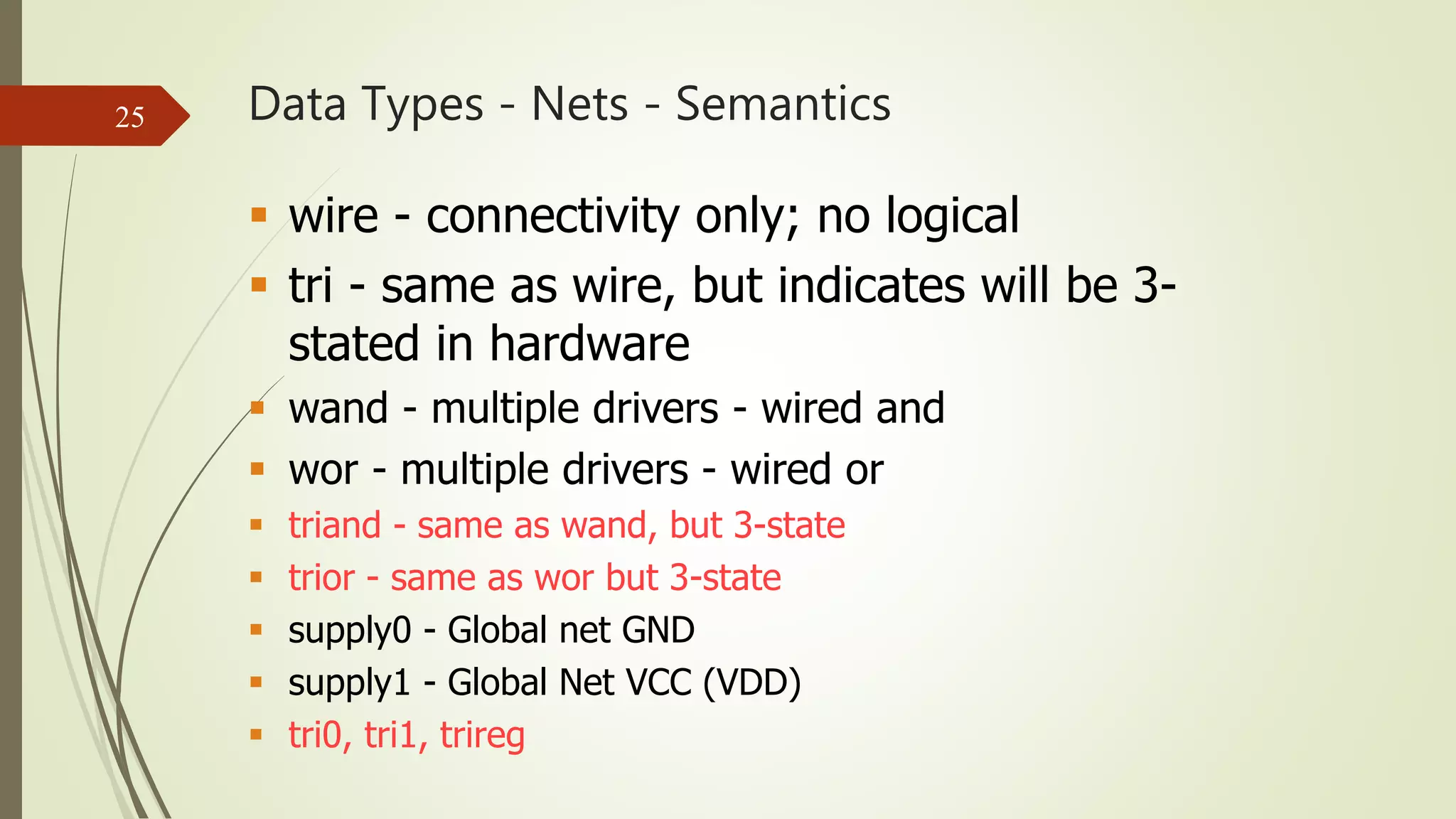
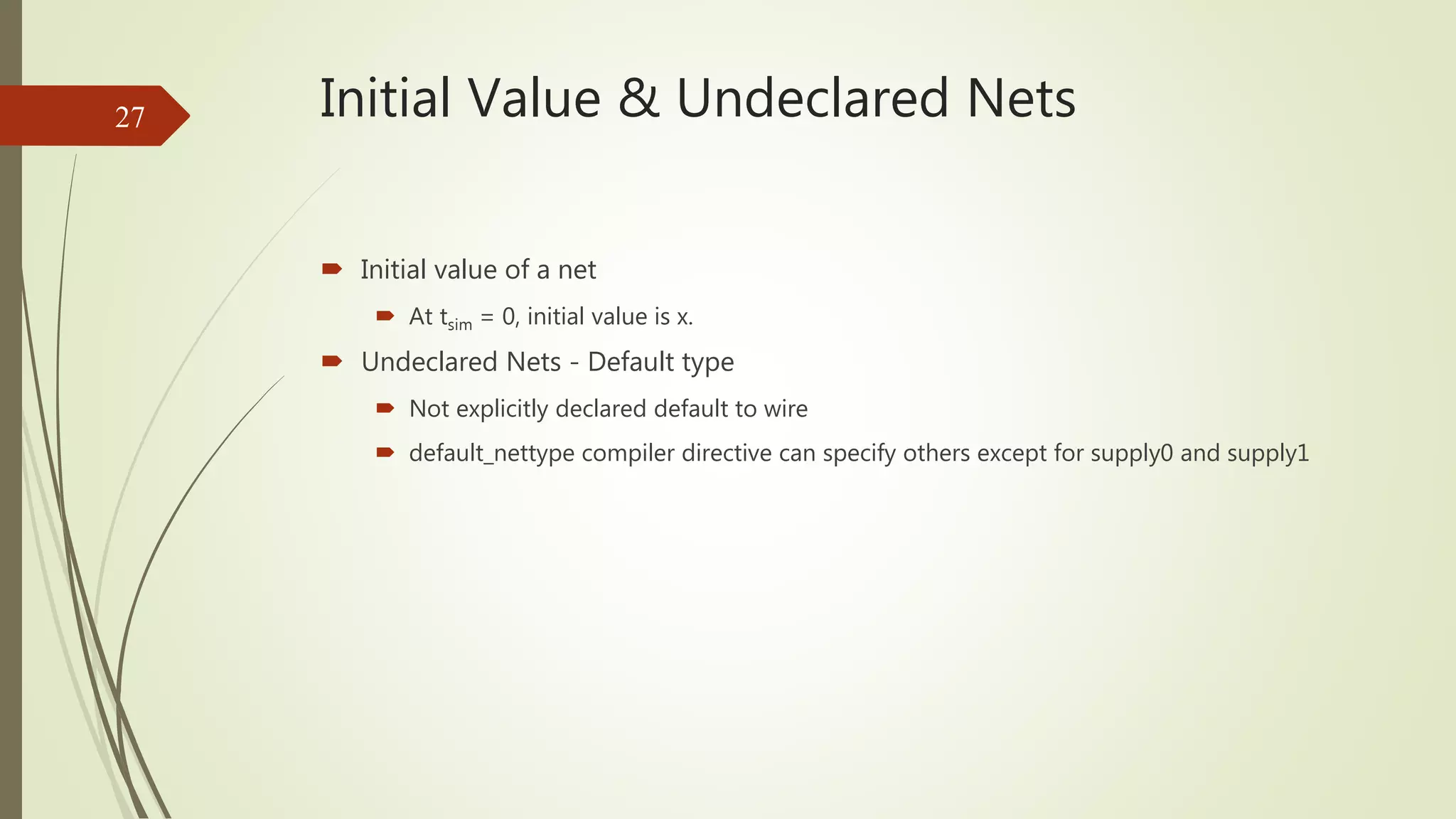
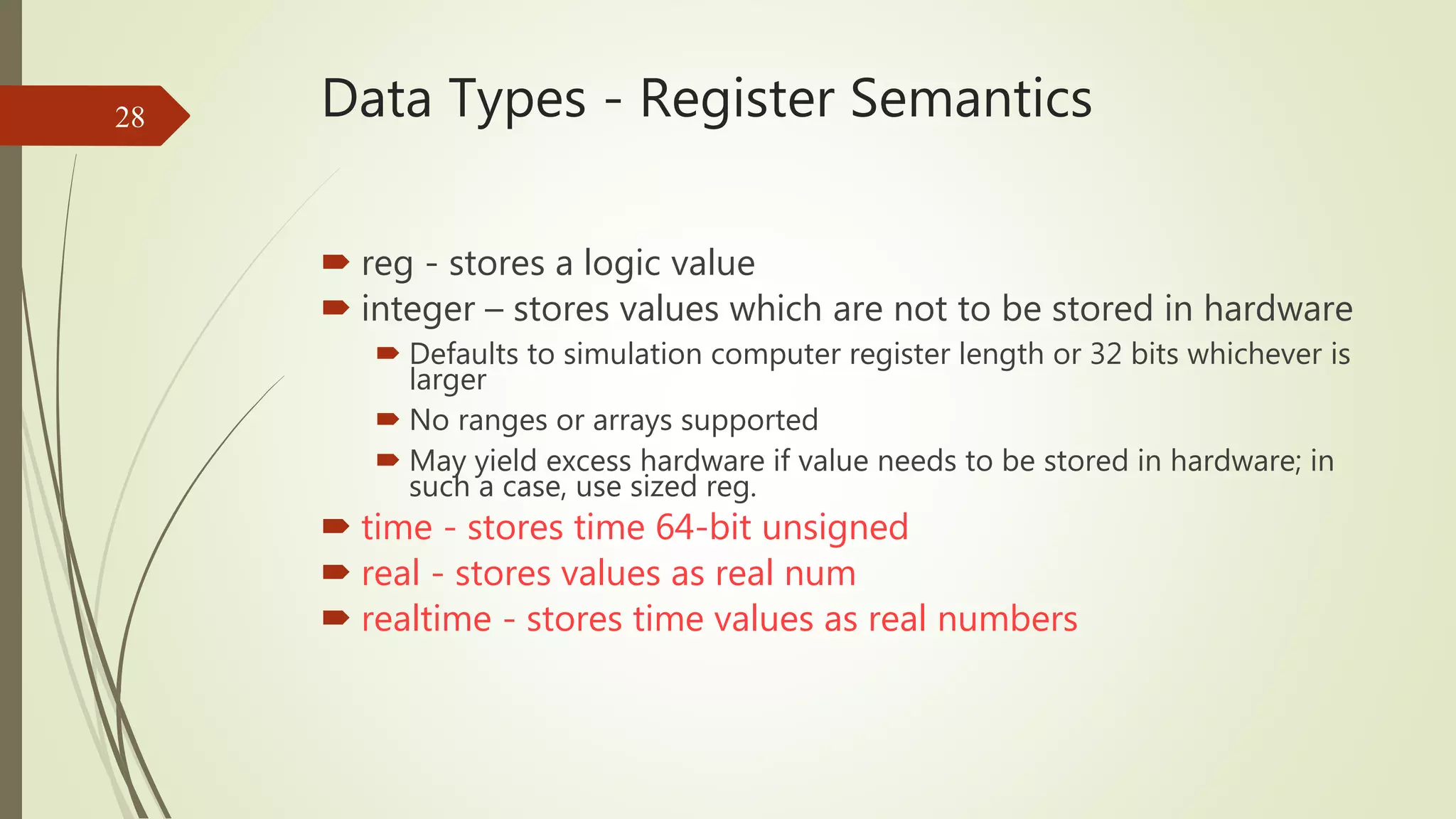
Distinguishes between nets and register types in Verilog, explaining their properties and examples.
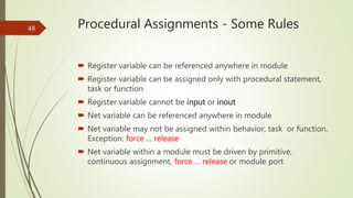
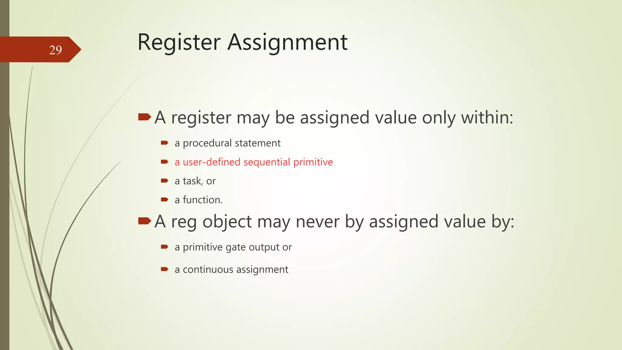
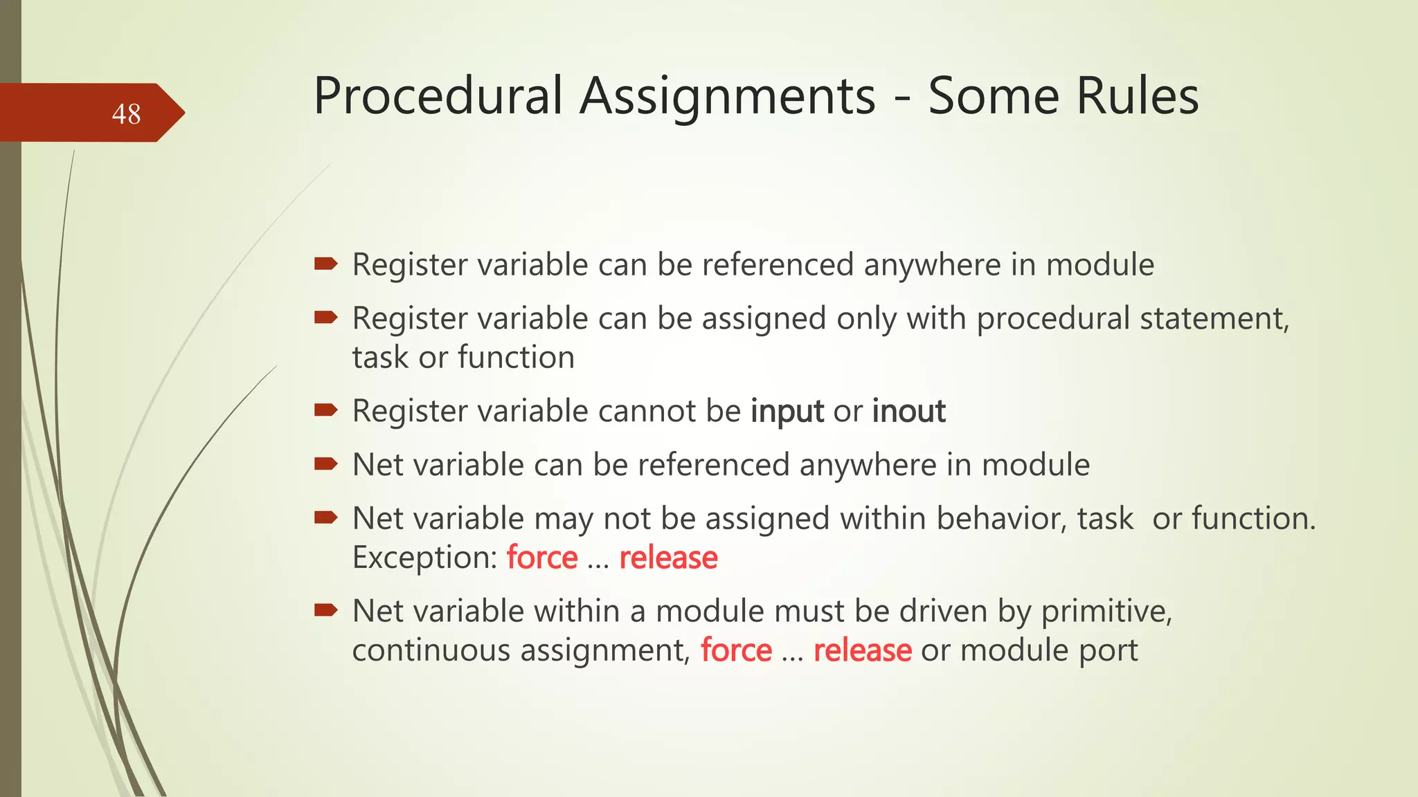
Explores different register types and assignment rules for variables in Verilog.
Describes how strings are stored and how parameters are declared and used in Verilog.
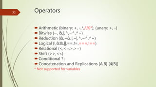
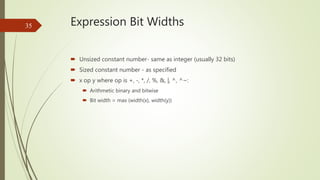
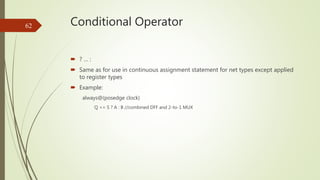
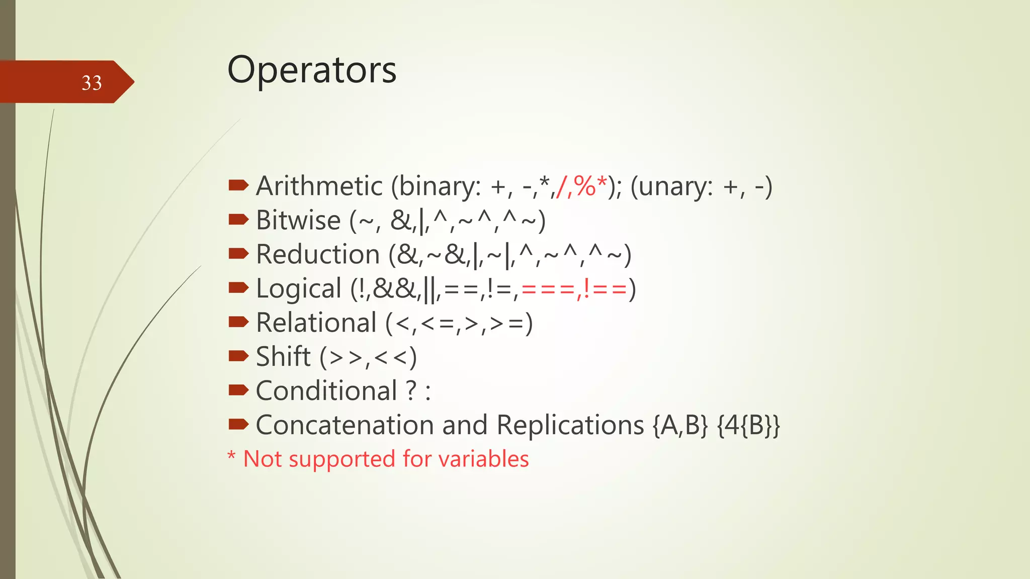
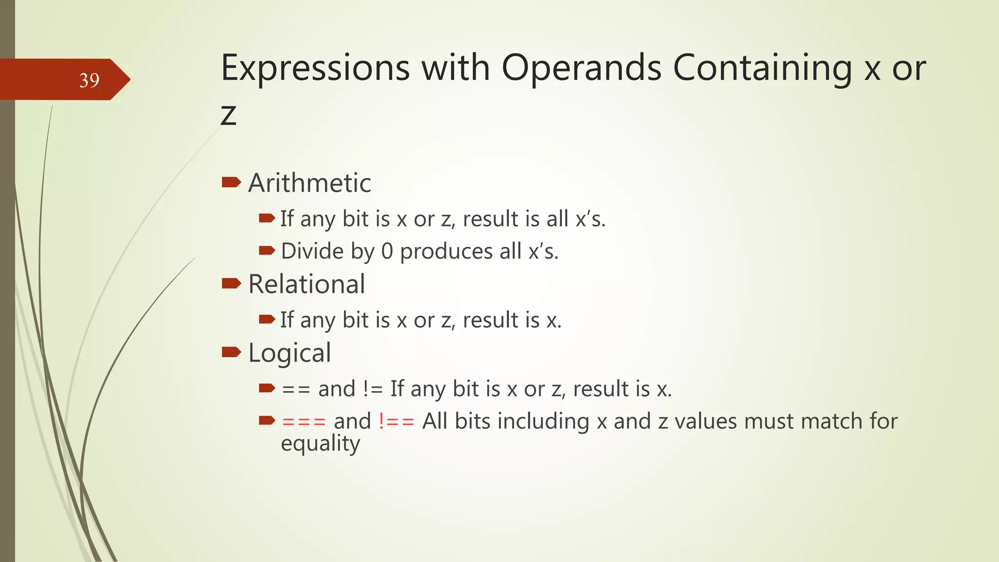
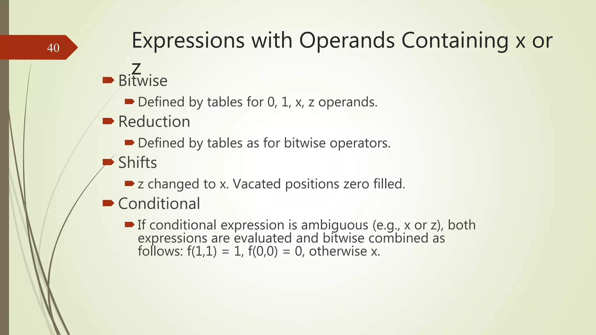
Lists the types of operators available in Verilog along with their functionality.
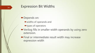
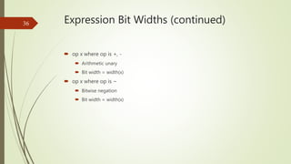
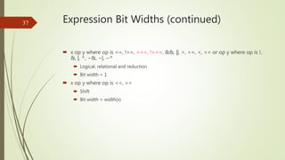
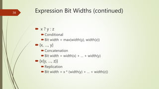
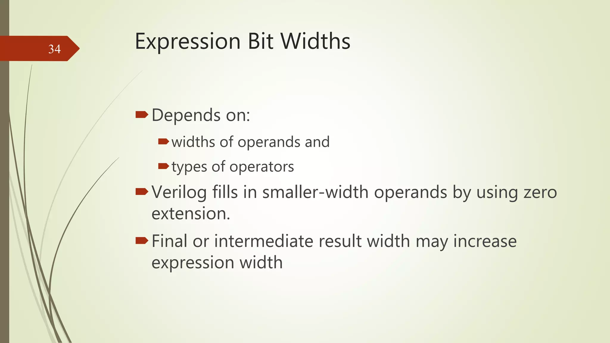
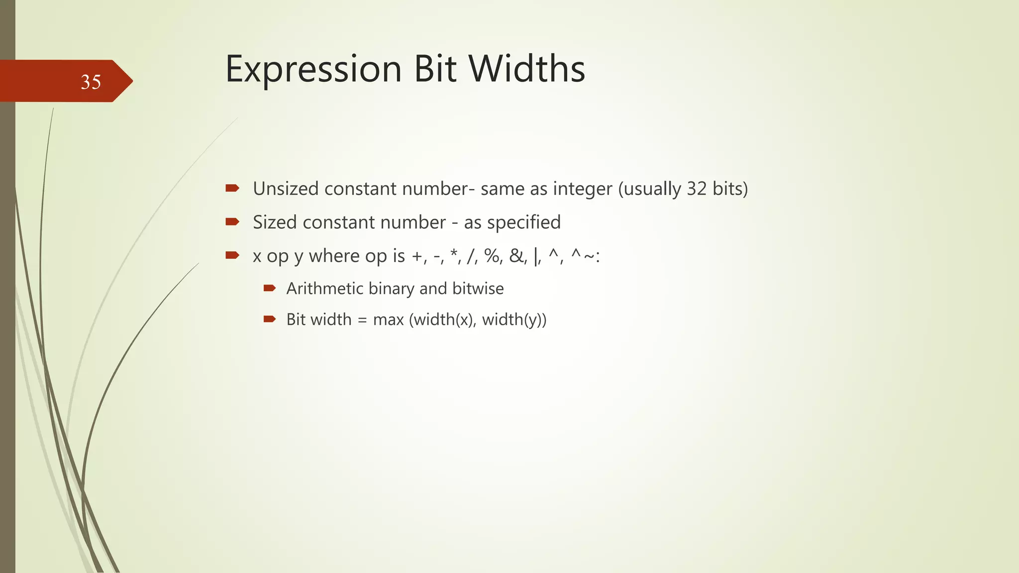
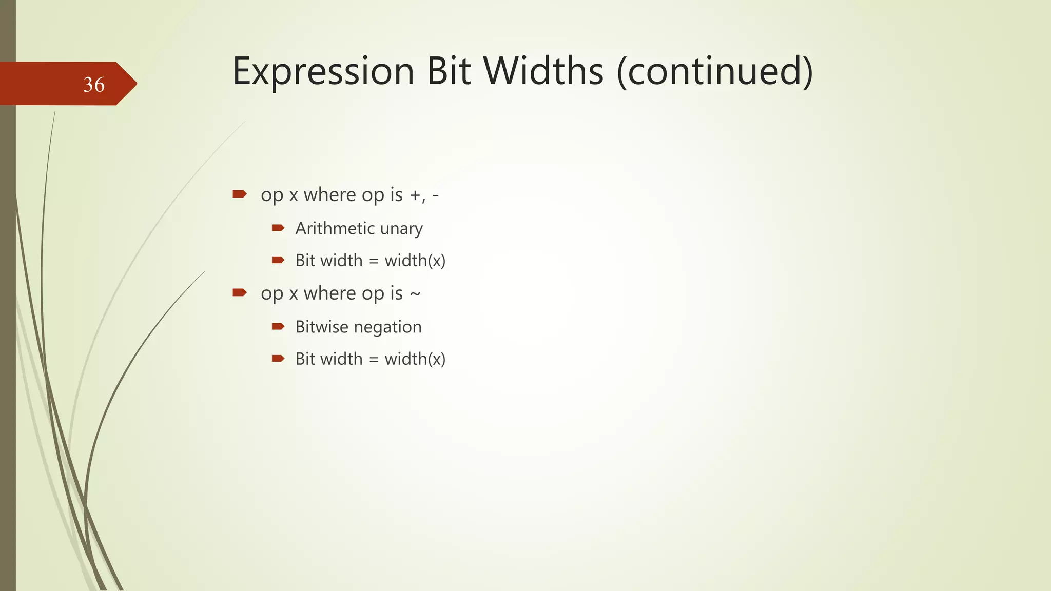
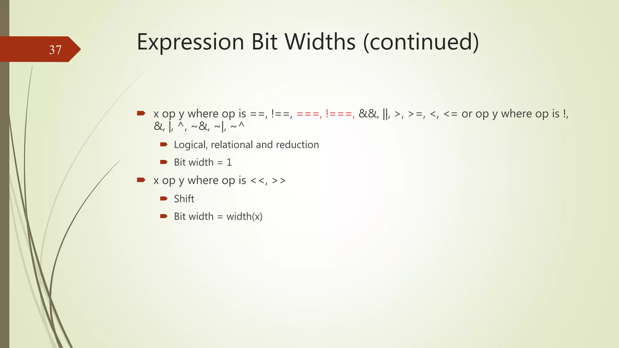
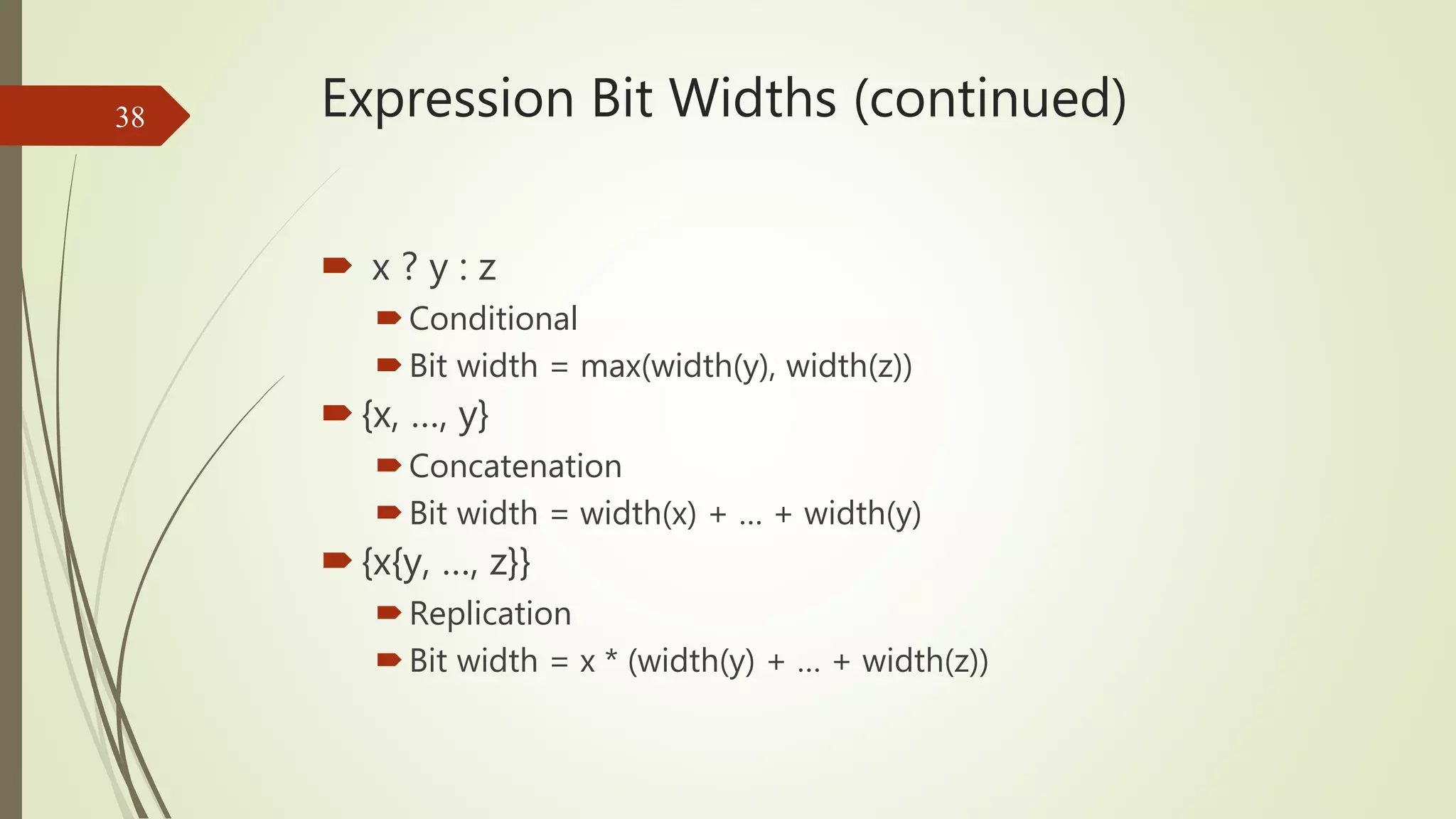
Covers how bit widths are determined in expressions and their implications in operations.
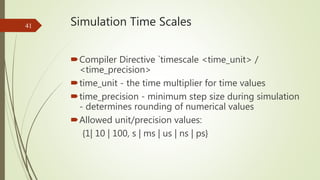
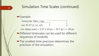
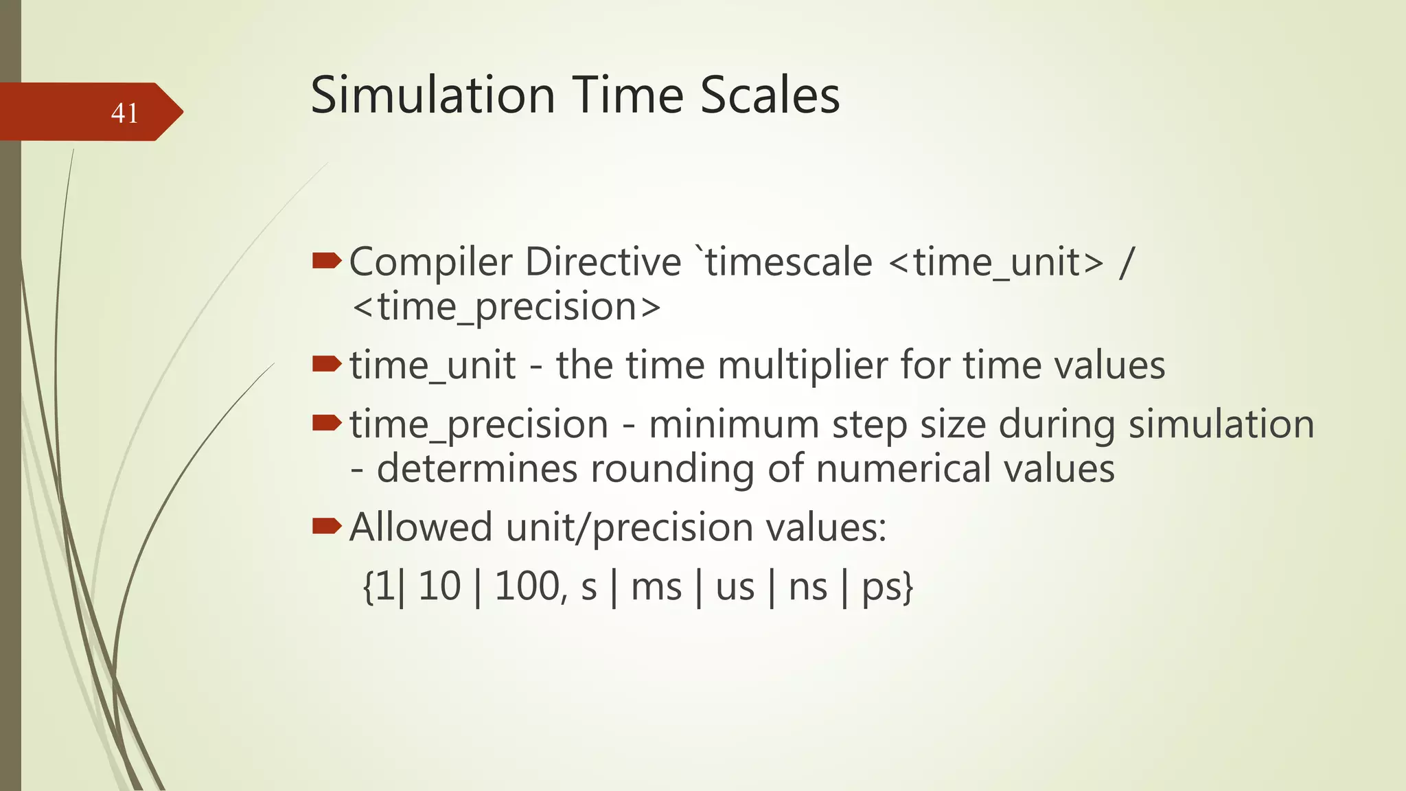
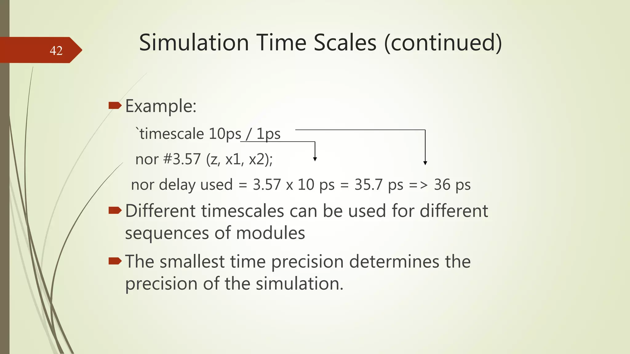
Introduces the concept of time units and precision in simulation time scales.
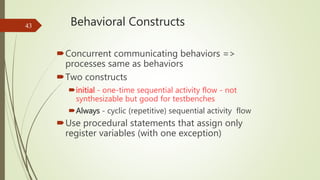
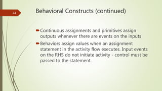
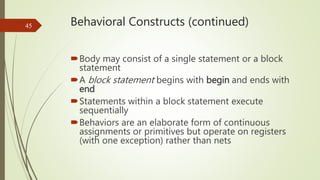
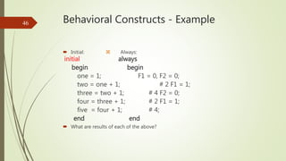
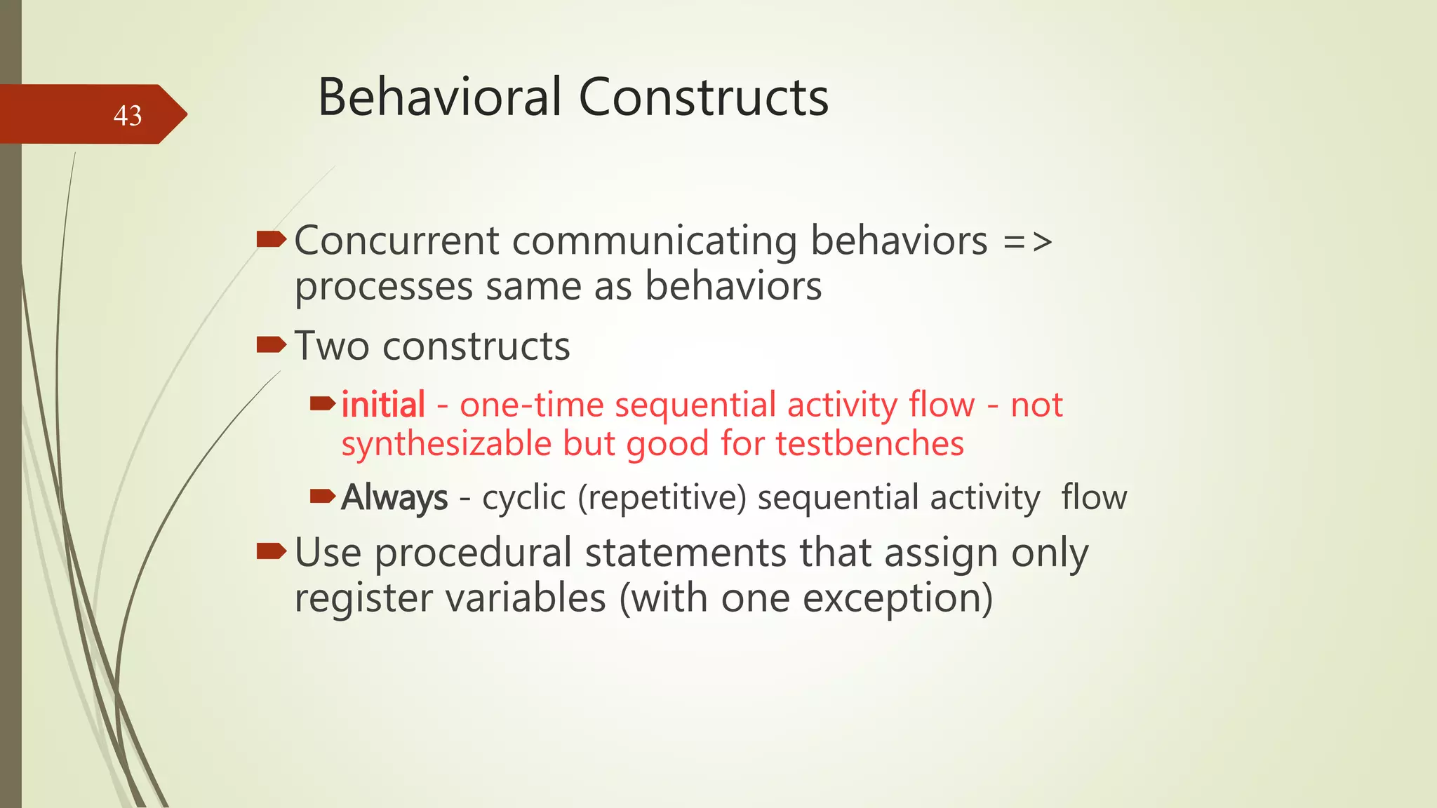
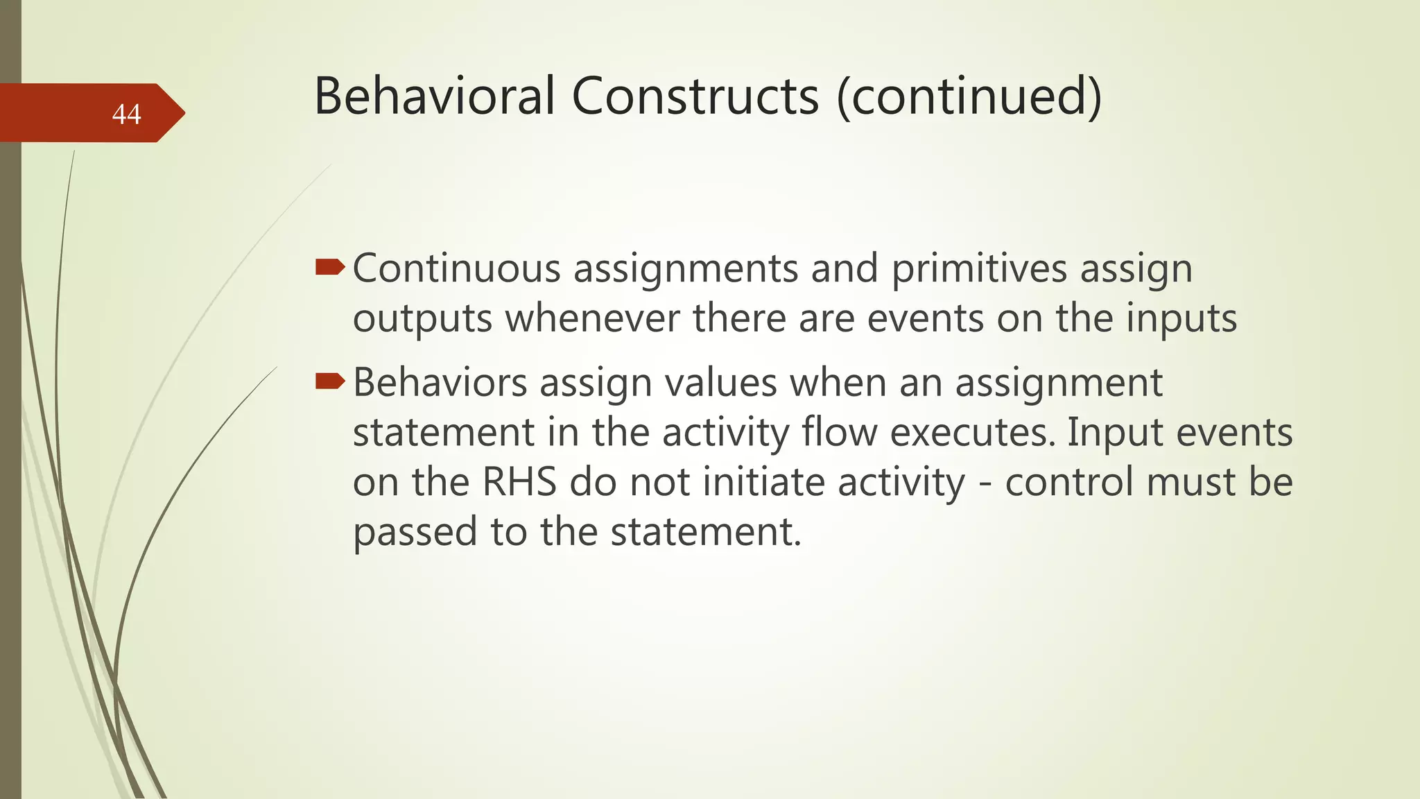
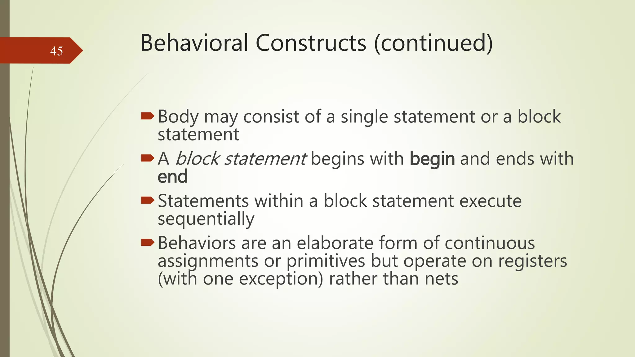
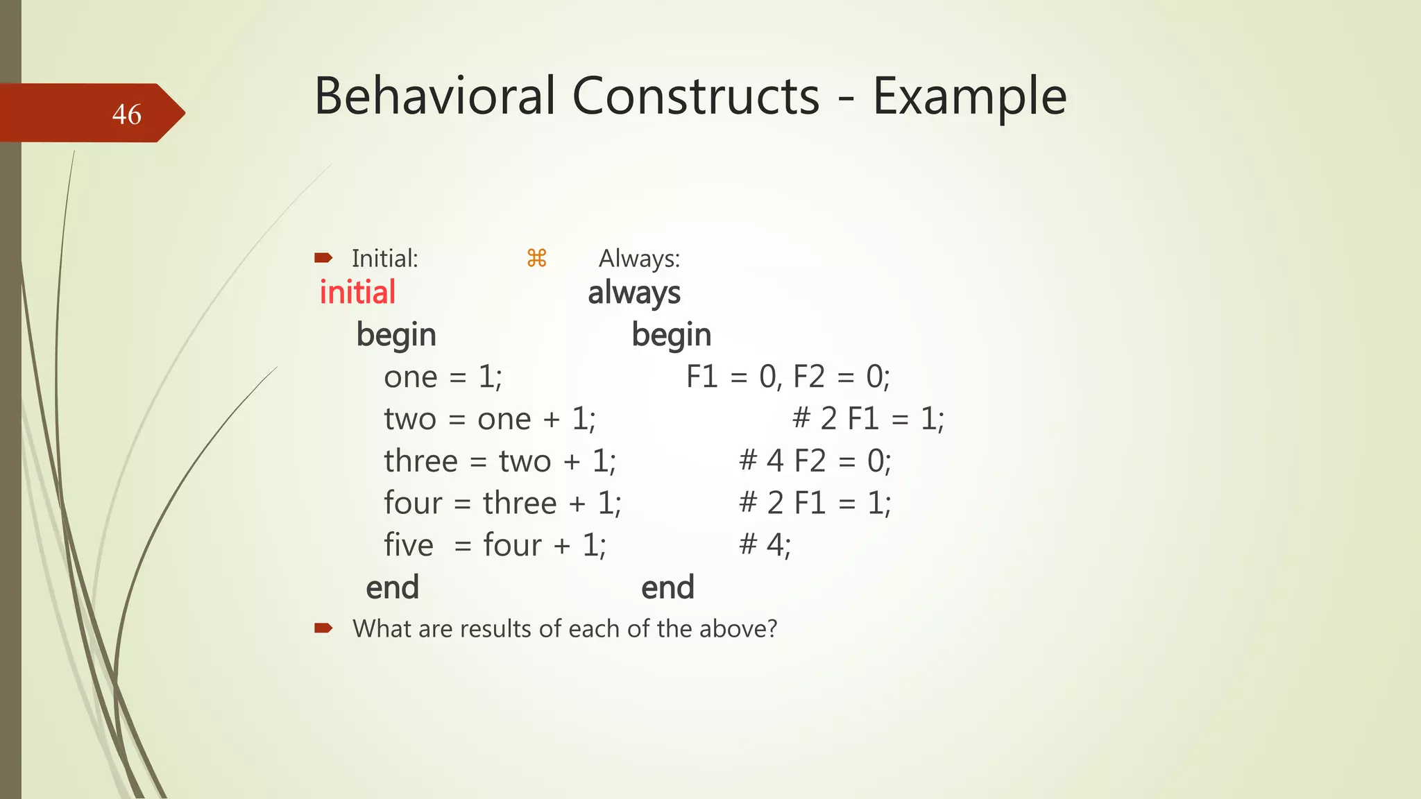
Examines the characteristics of behavioral constructs in Verilog, including procedural flow.
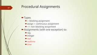
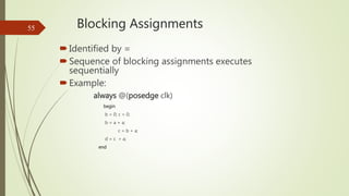
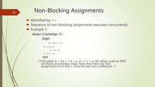
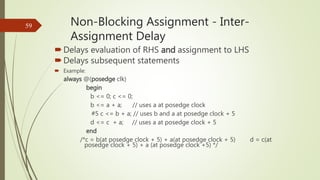
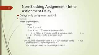
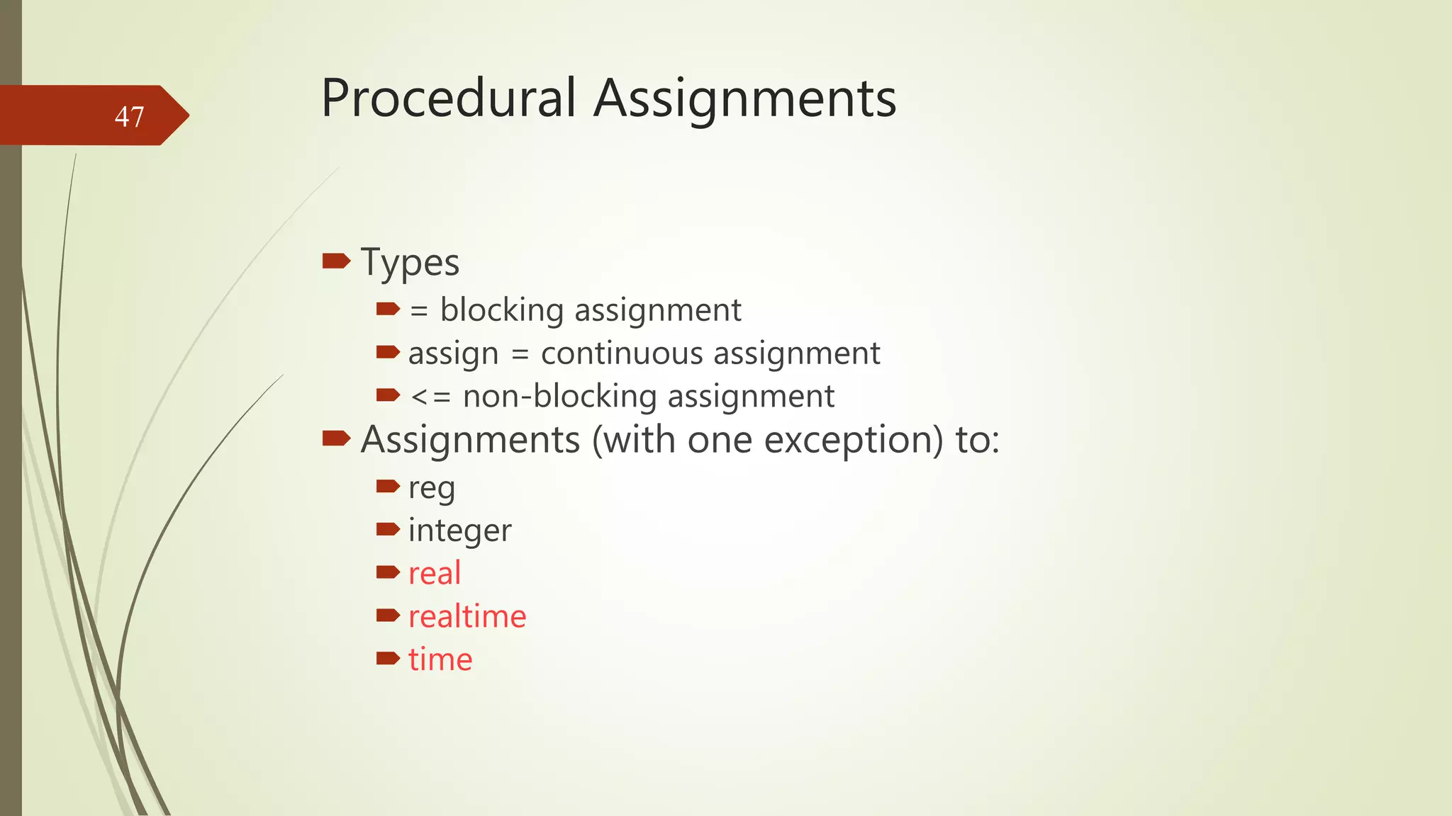
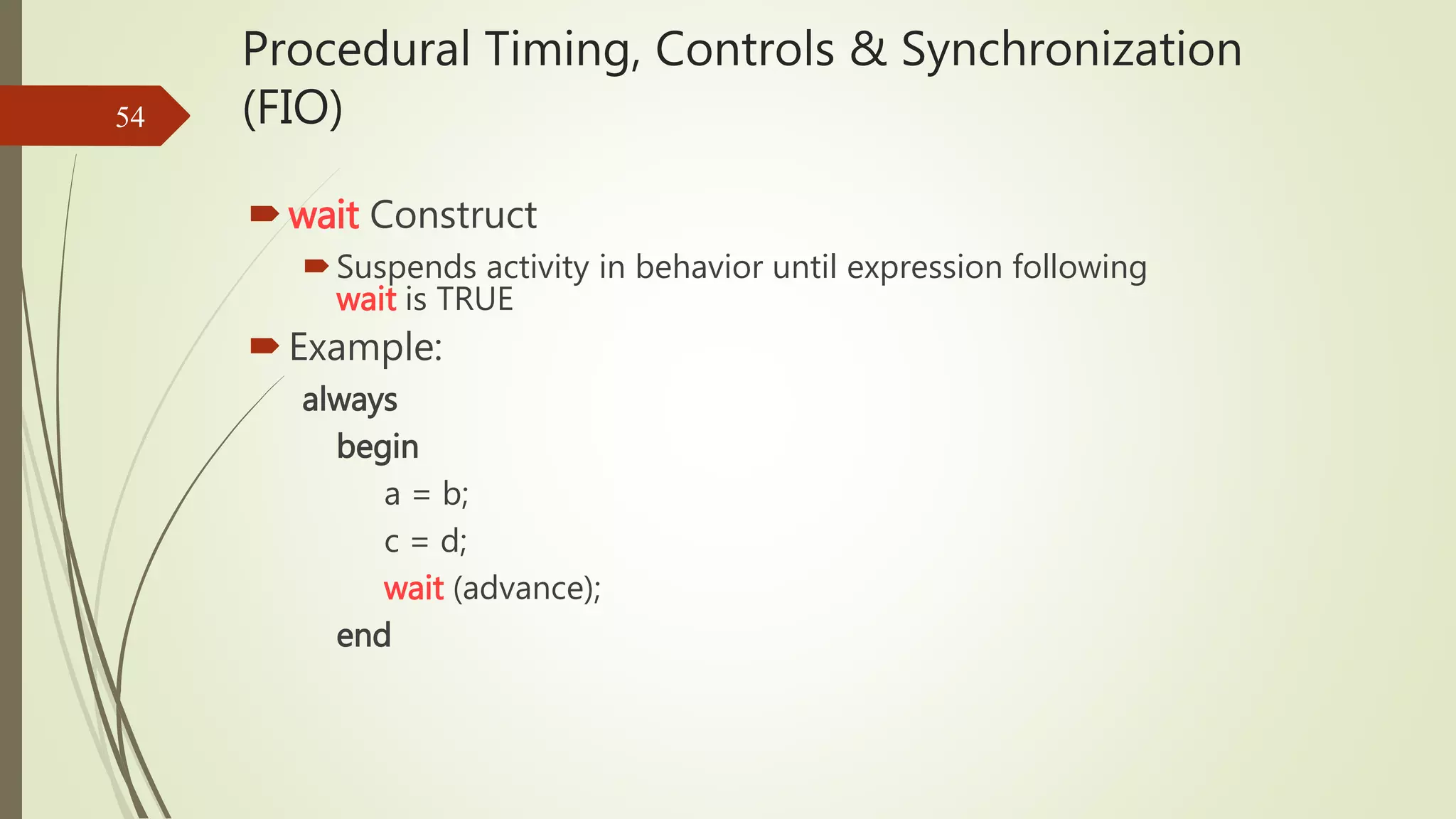
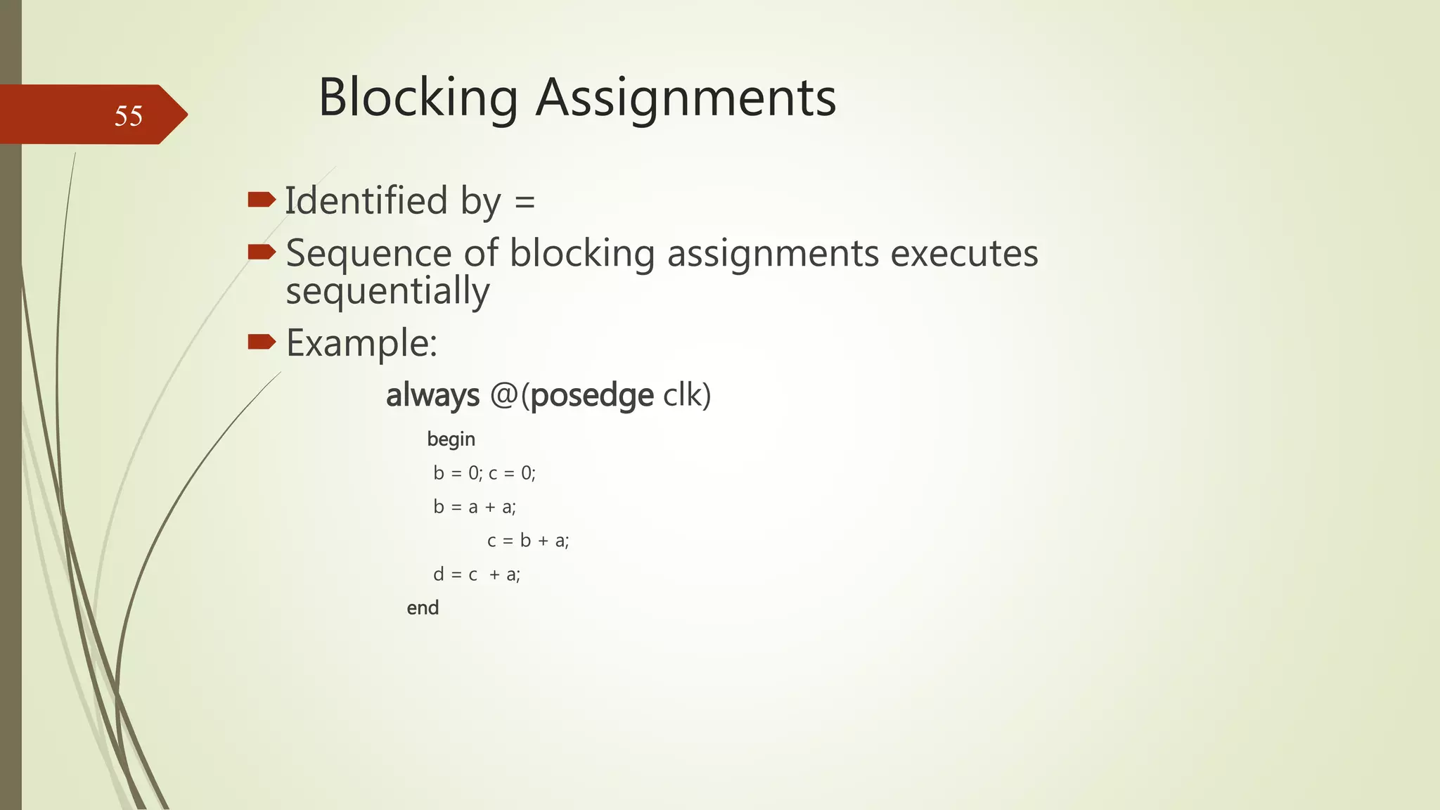
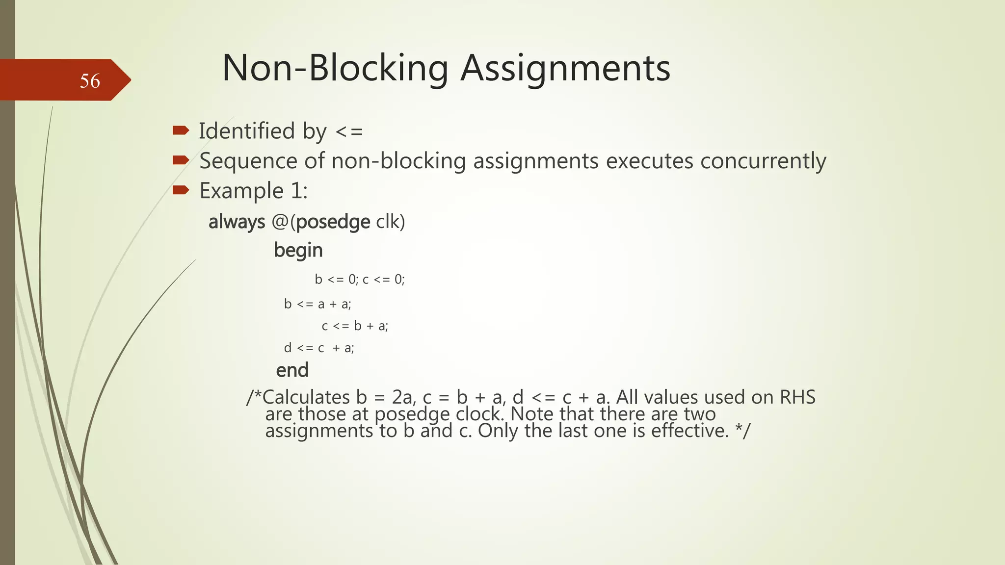
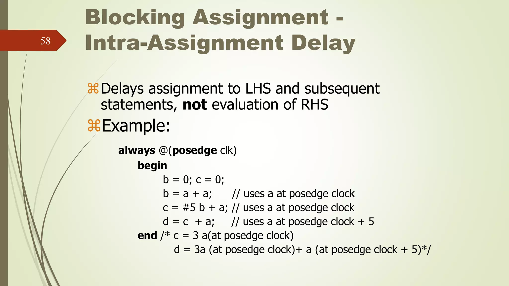
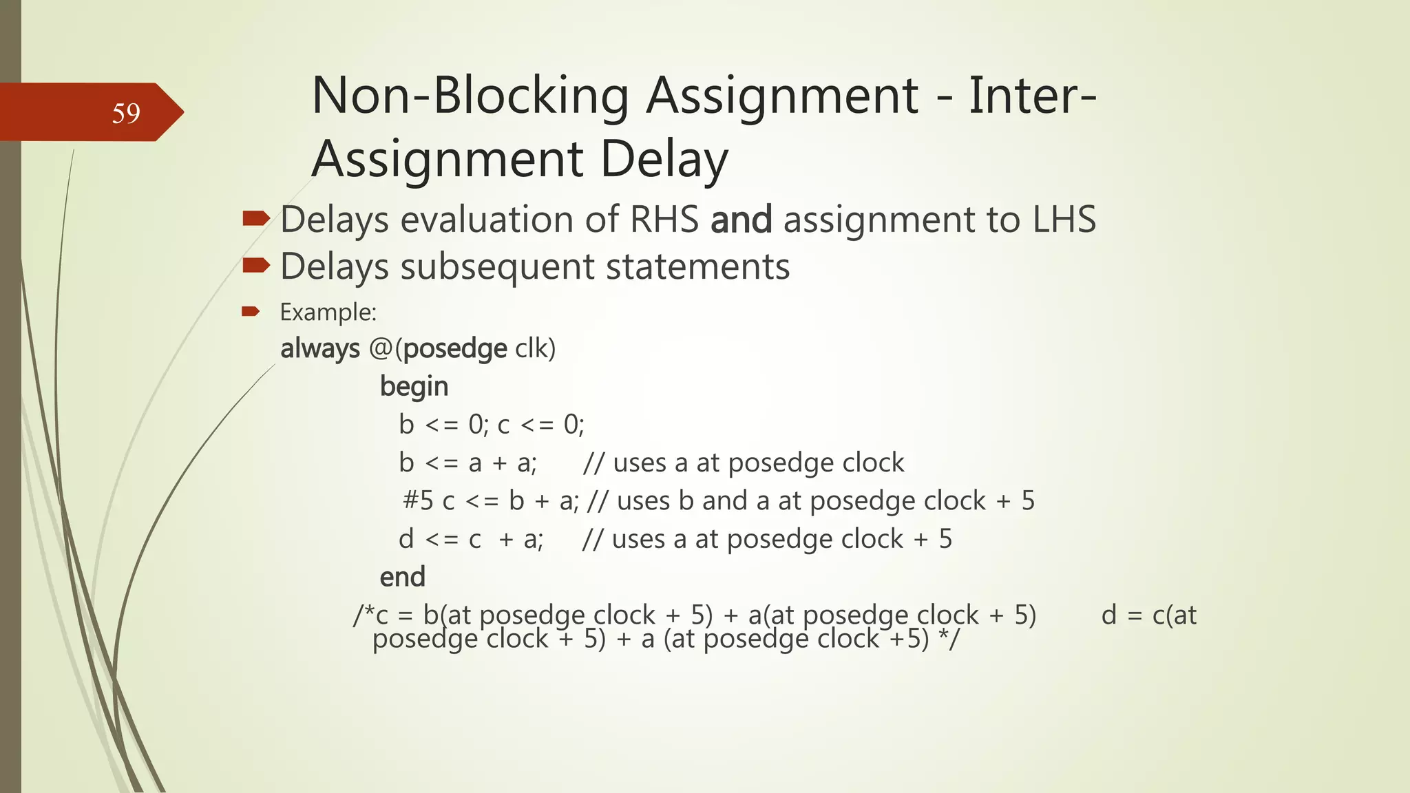
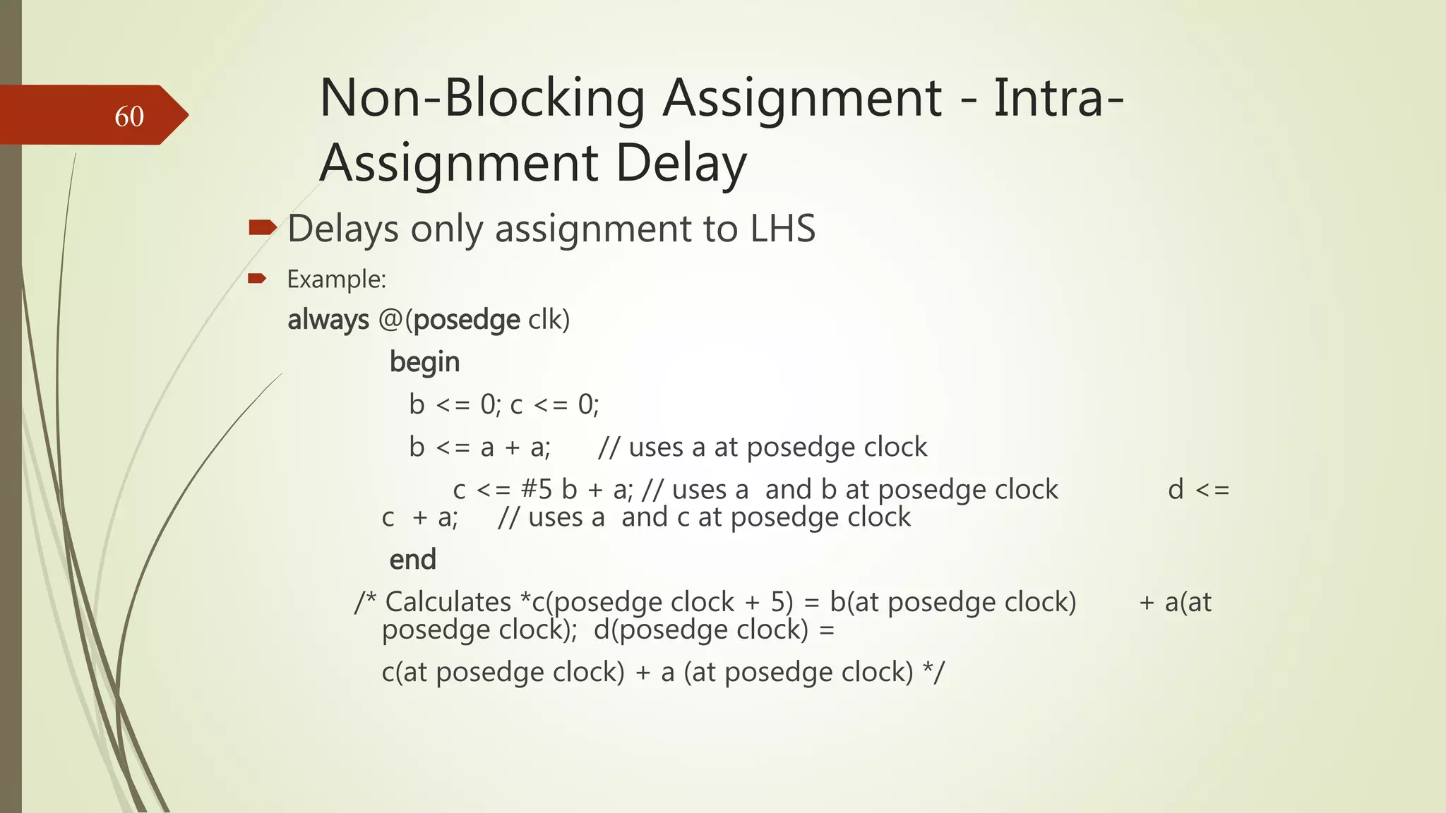
Details the types of assignments and their rules, including non-blocking and blocking assignments.
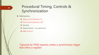
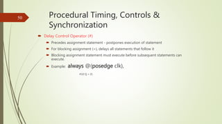
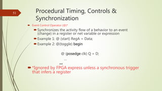
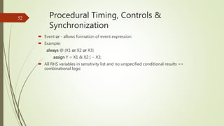
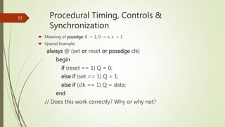
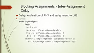
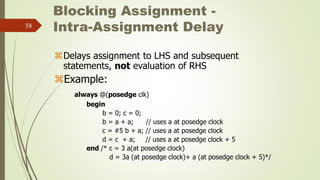
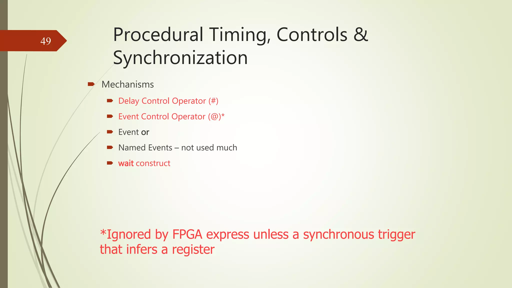
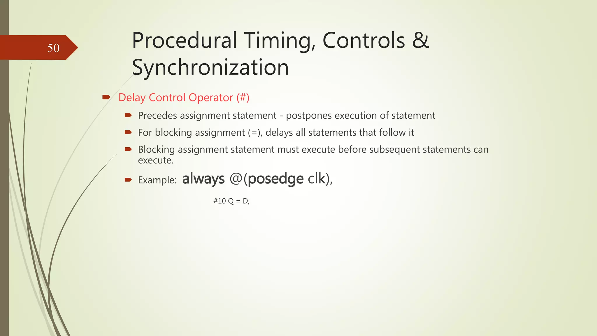
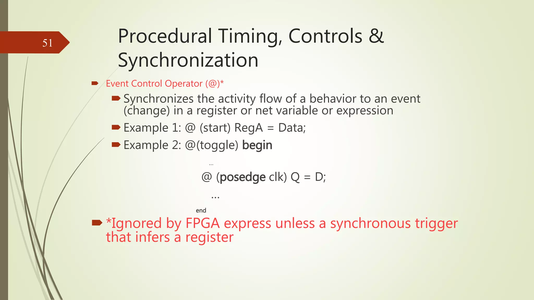
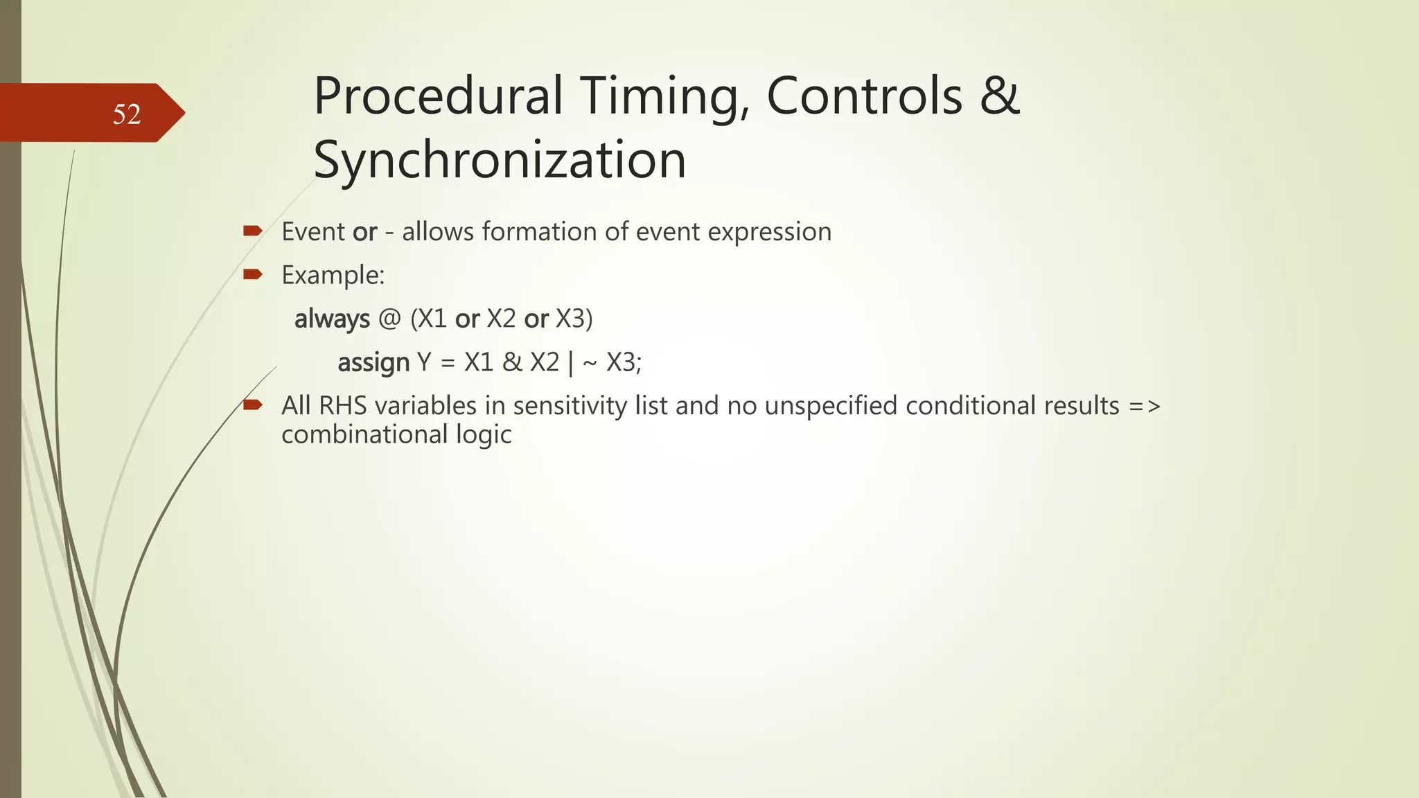
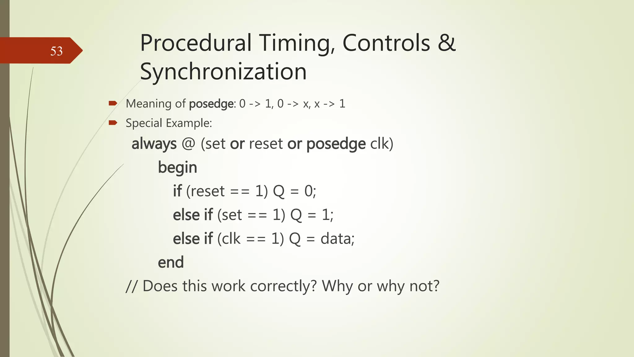
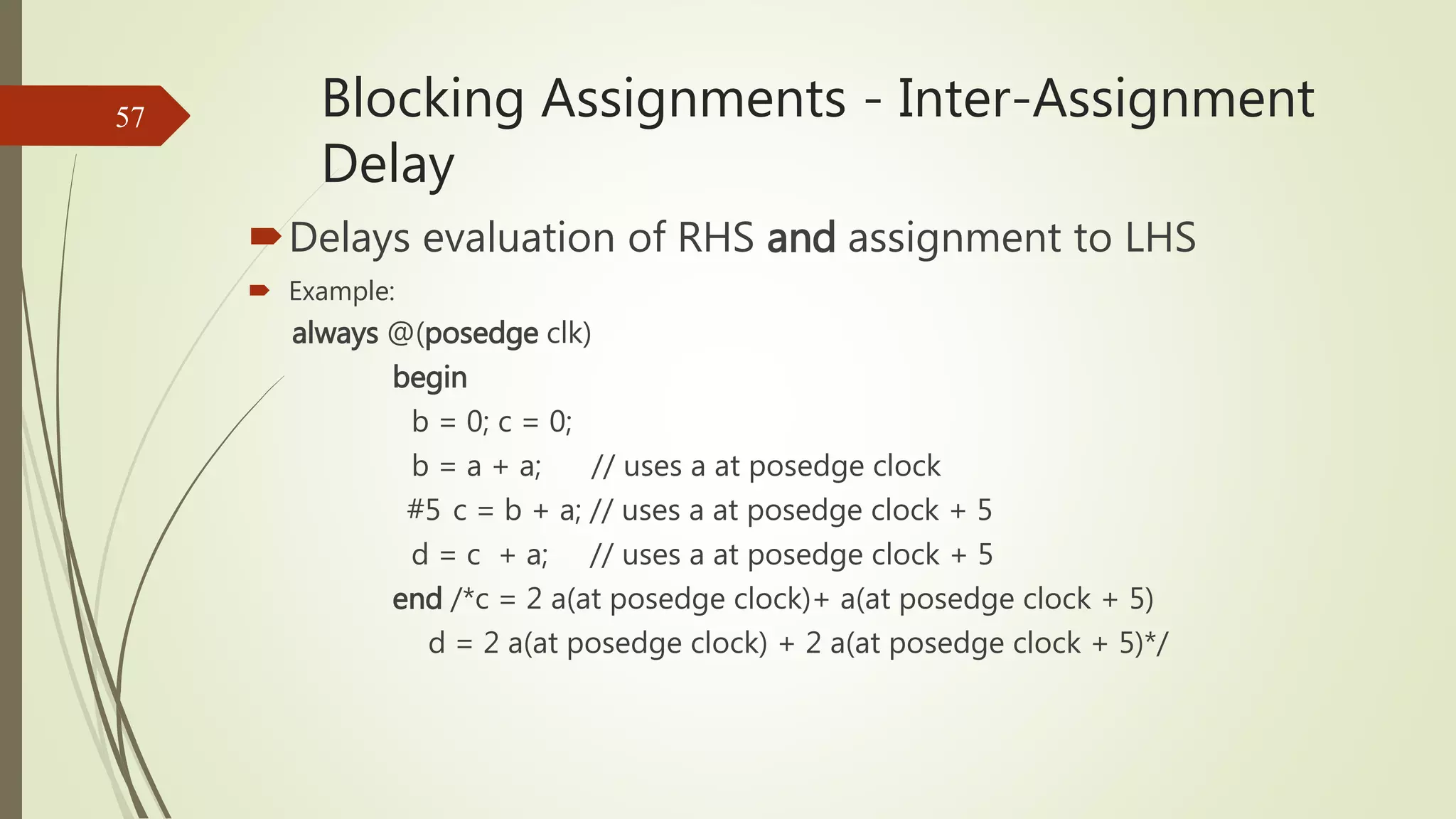
Explains delay and event control mechanisms for managing procedural flow and timing.
Contrasts blocking and non-blocking assignments and their timing behavior in execution.
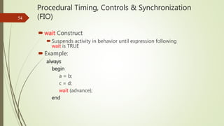
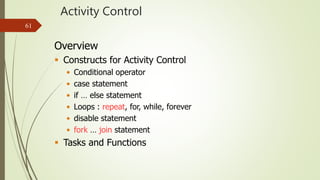
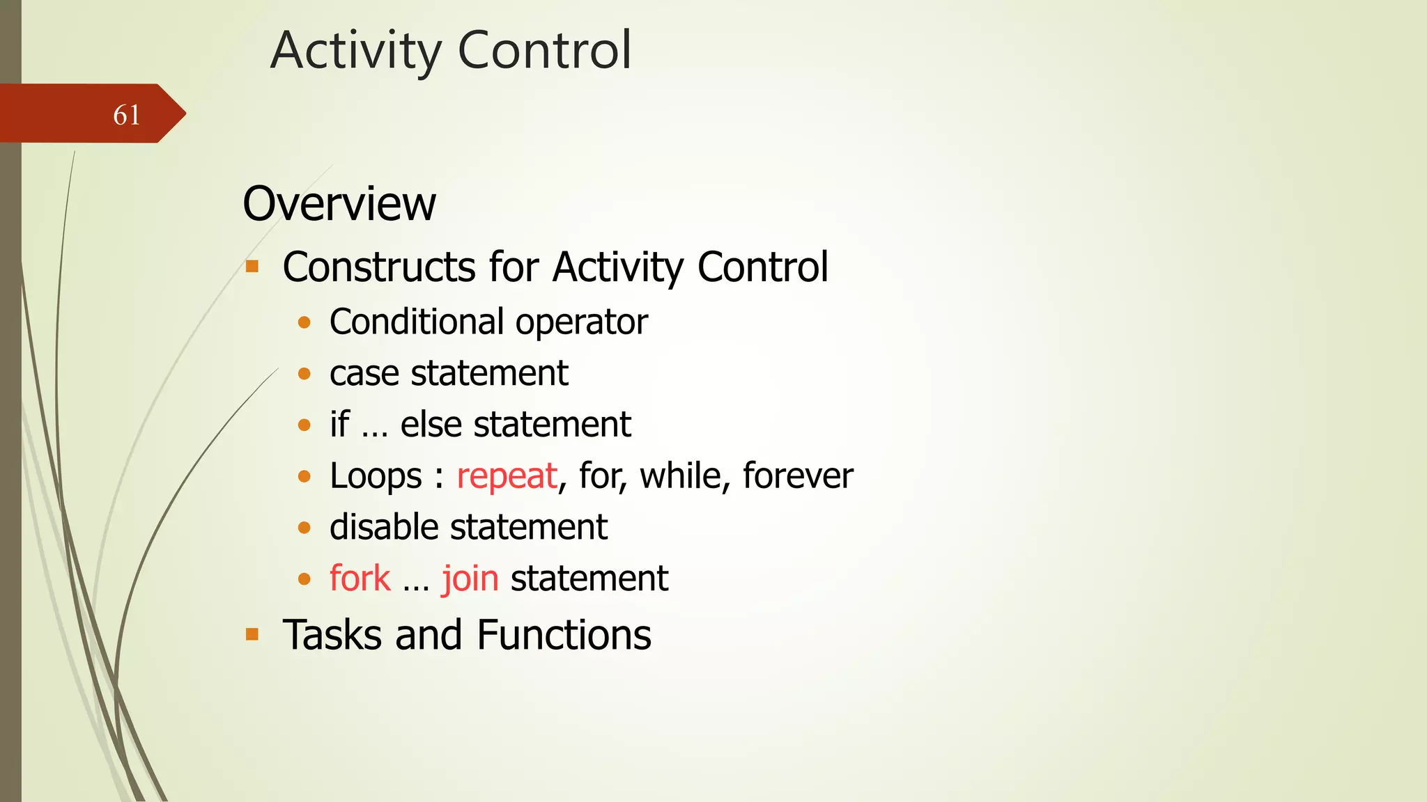
Introduces constructs for controlling activity in Verilog, including loops and tasks.
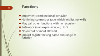
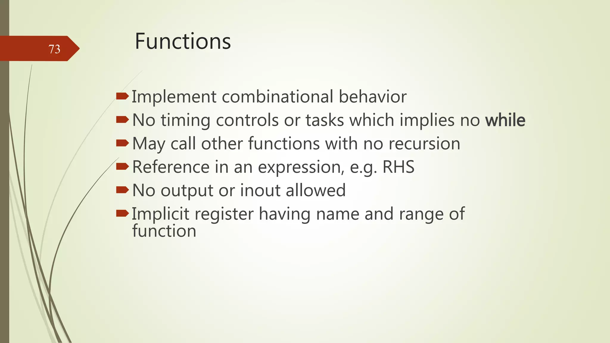
Describes how tasks and functions are defined in Verilog, including examples.
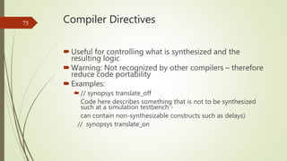
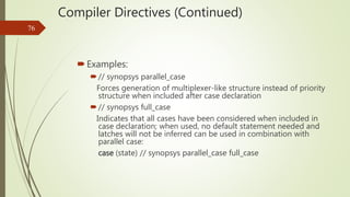
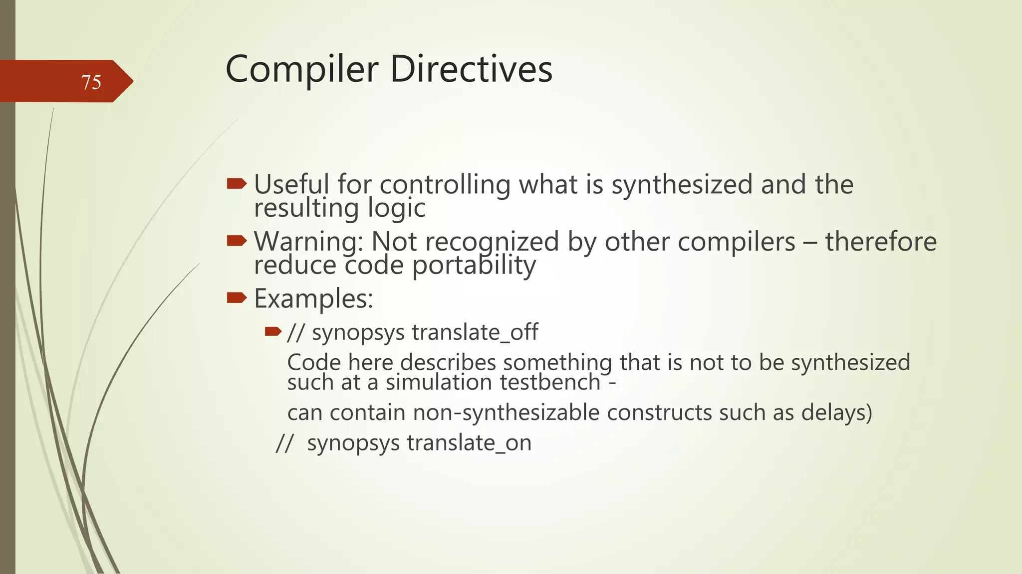
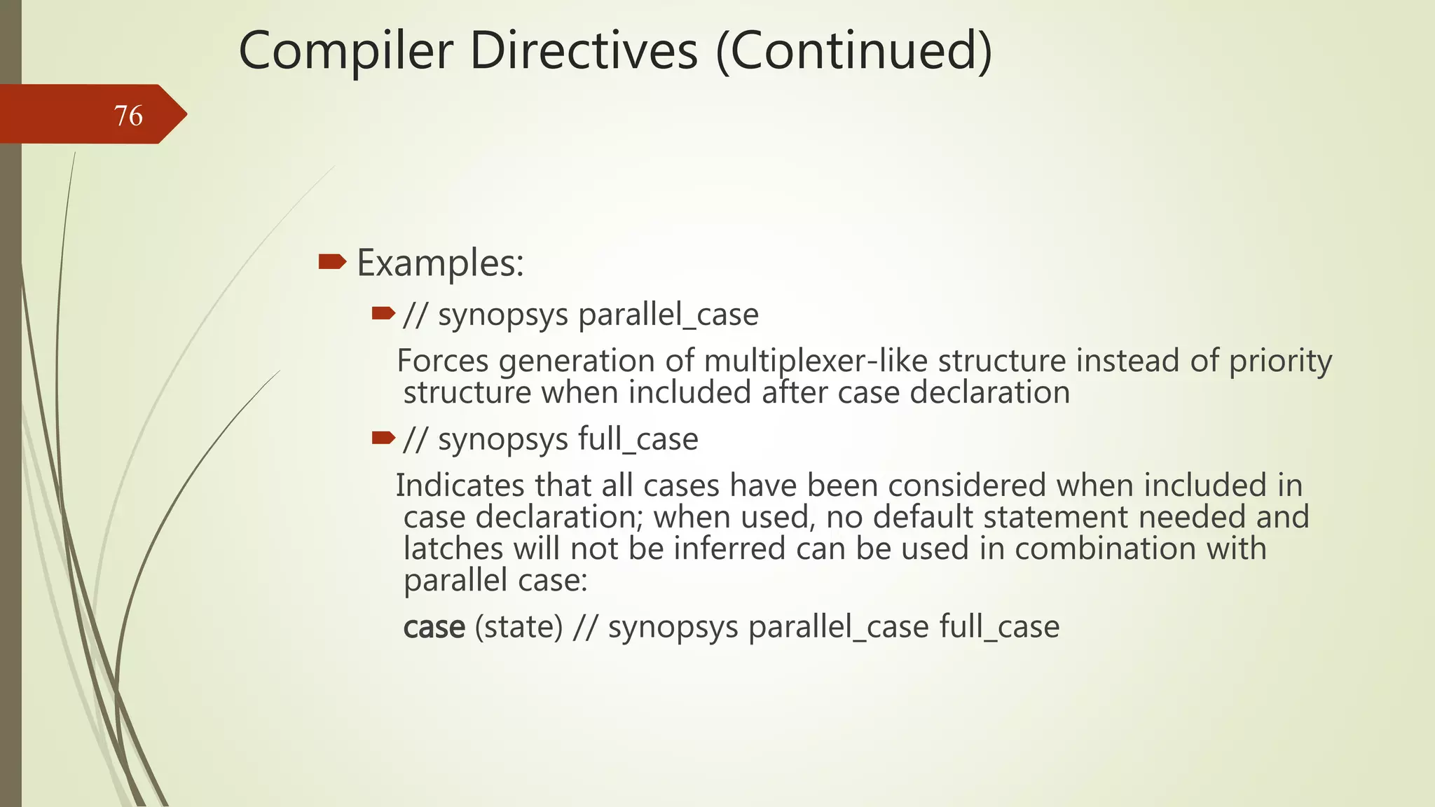
Discusses directives for controlling synthesis and code portability in Verilog.
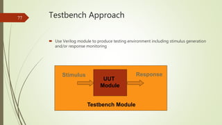
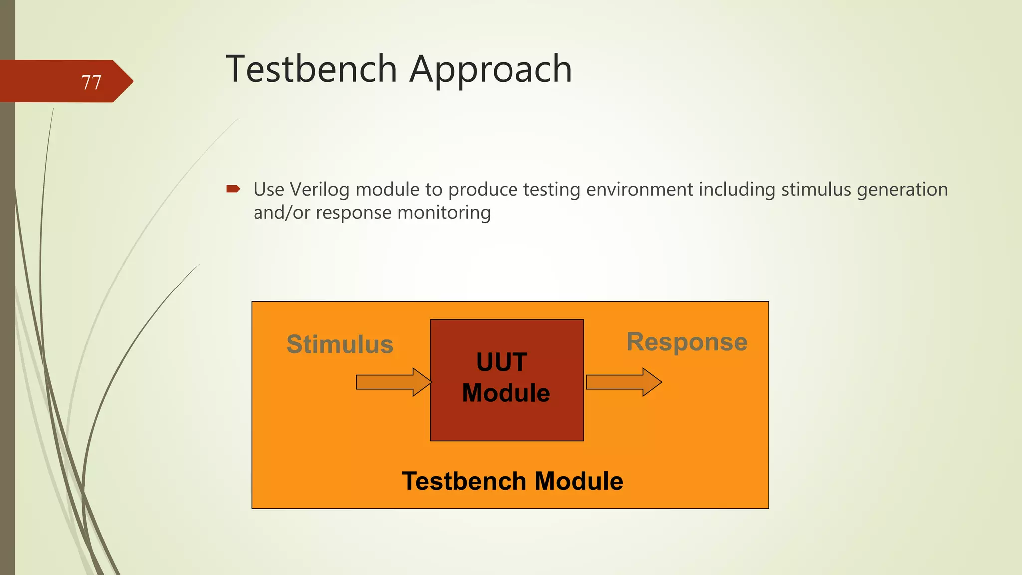
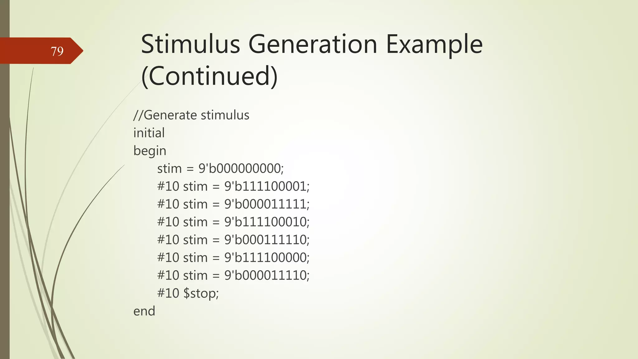
Explains the testbench approach for stimulus generation and testing of Verilog modules.


