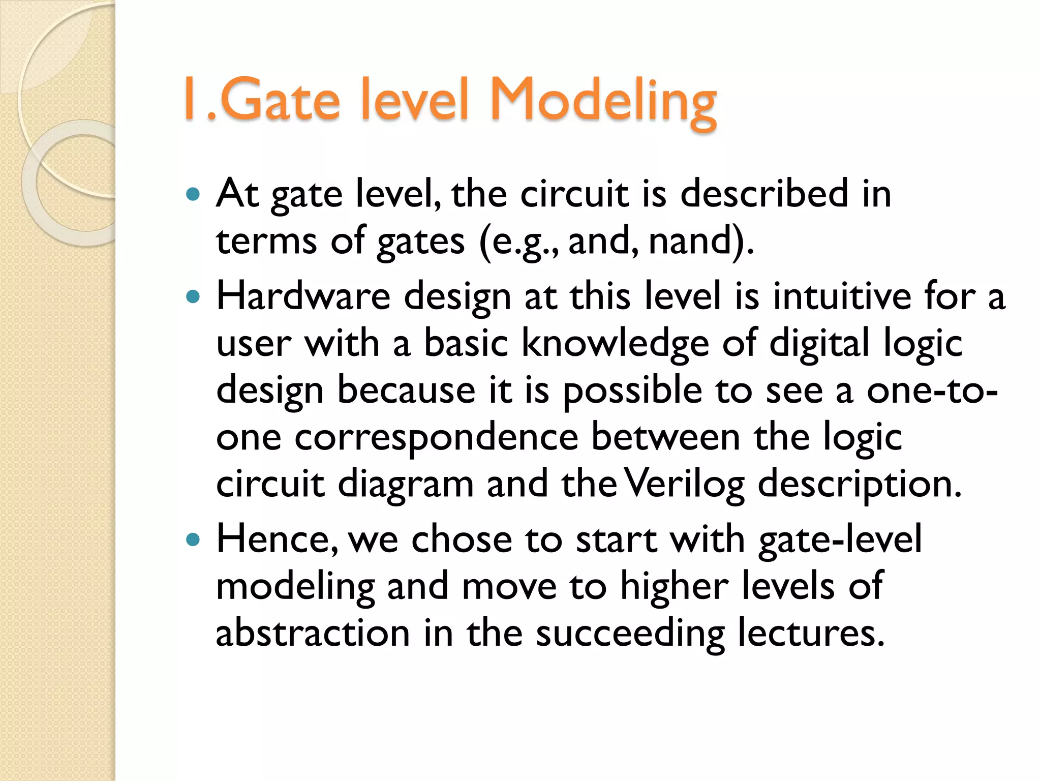
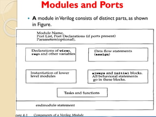
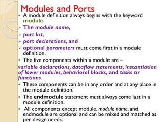
This document provides an overview of Verilog hardware description language (HDL) and gate-level modeling. It discusses the key components of Verilog modules like module definition, ports, parameters and instantiations. It describes how to define ports and connect ports in a module. It also covers different gate primitives in Verilog like AND, OR, NOT etc. and how to describe gate-level designs using these primitives by specifying gate connections and delays. Finally, it mentions some references for further reading on Verilog HDL and digital logic design.

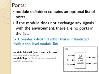
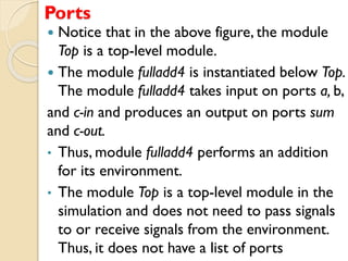
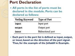
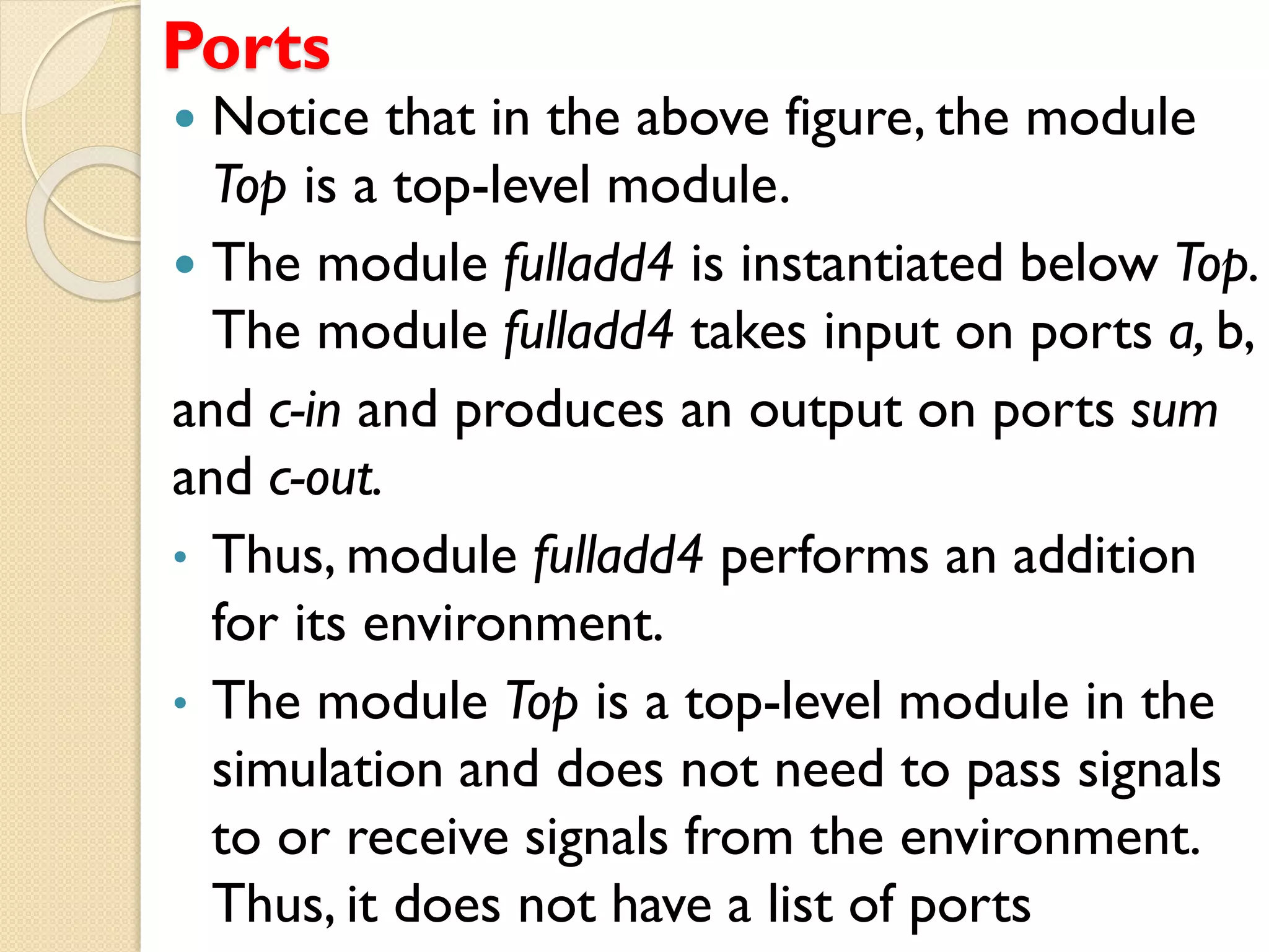
![module fulladd4(sum, c-out, a, b, c-in);
//Begin port declarations section
output [3 : 0] sum;
output c-cout;
input [3:0] a, b;
input c-in;
//End port declarations section
...
<module internals>
...
endmodule](https://image.slidesharecdn.com/vhdlgatelevelmodelling-210621063850/85/VHDL-gate-level-modelling-13-320.jpg)


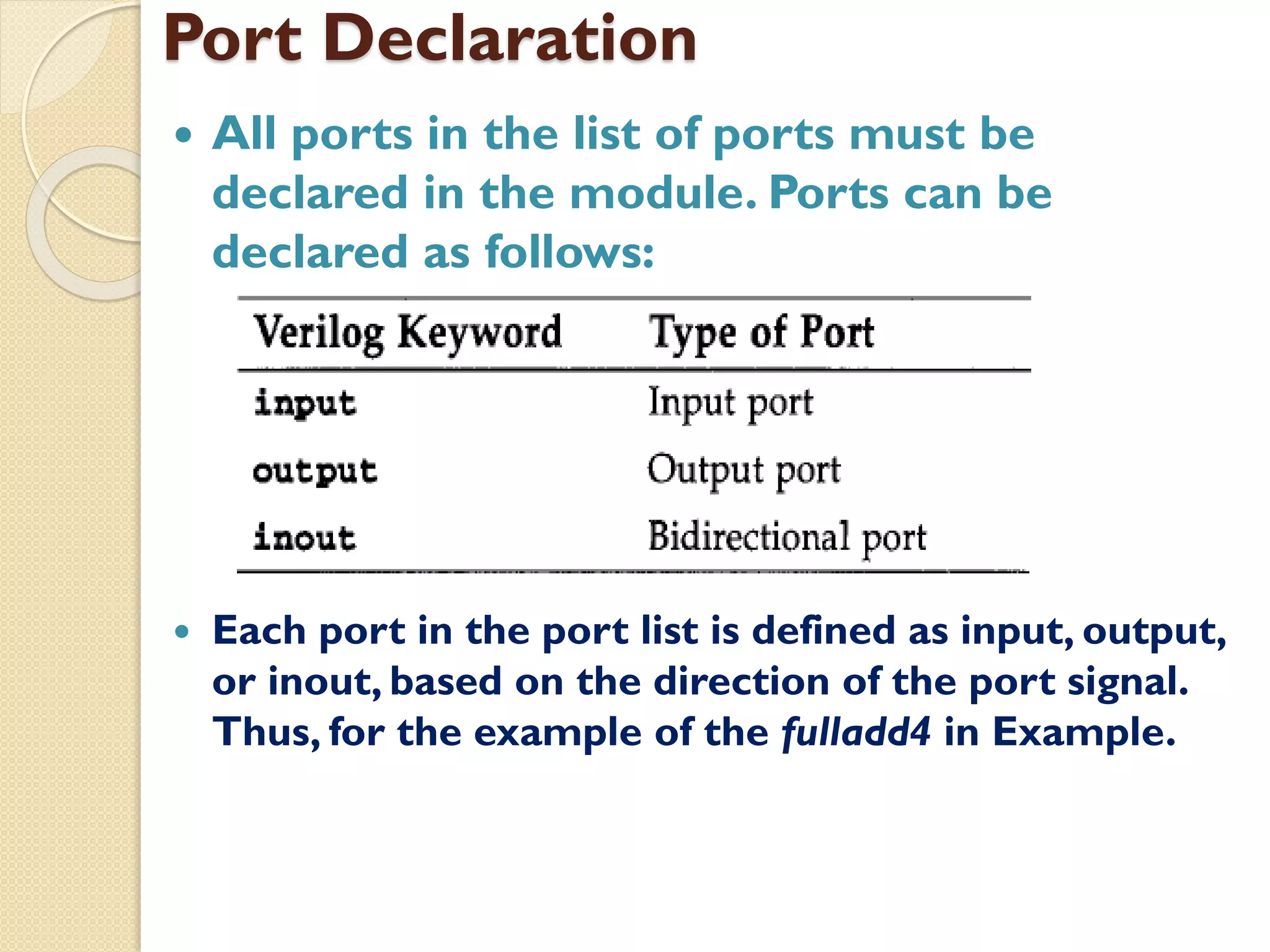
![module fulladd4(sum, c-out, a, b, c-in);
//Begin port declarations section
output [3 : 0] sum;
output c-cout;
input [3:0] a, b;
input c-in;
//End port declarations section
...
<module internals>
...
endmodule](https://image.slidesharecdn.com/vhdlgatelevelmodelling-210621063850/75/VHDL-gate-level-modelling-13-2048.jpg)